JP4651184B2 - Method and apparatus for registering, displaying and decoding spatially aligned information - Google Patents
Method and apparatus for registering, displaying and decoding spatially aligned information Download PDFInfo
- Publication number
- JP4651184B2 JP4651184B2 JP2000371332A JP2000371332A JP4651184B2 JP 4651184 B2 JP4651184 B2 JP 4651184B2 JP 2000371332 A JP2000371332 A JP 2000371332A JP 2000371332 A JP2000371332 A JP 2000371332A JP 4651184 B2 JP4651184 B2 JP 4651184B2
- Authority
- JP
- Japan
- Prior art keywords
- image
- information
- code
- glyph
- substrate
- Prior art date
- Legal status (The legal status is an assumption and is not a legal conclusion. Google has not performed a legal analysis and makes no representation as to the accuracy of the status listed.)
- Expired - Fee Related
Links
- 238000000034 method Methods 0.000 title description 38
- 239000000758 substrate Substances 0.000 claims description 105
- 239000002131 composite material Substances 0.000 claims description 31
- 230000001502 supplementing effect Effects 0.000 claims 2
- 238000012545 processing Methods 0.000 description 35
- 238000010586 diagram Methods 0.000 description 23
- 238000004891 communication Methods 0.000 description 19
- 102100034432 Protein NDRG4 Human genes 0.000 description 18
- 101150102256 ndrg4 gene Proteins 0.000 description 18
- 230000000875 corresponding effect Effects 0.000 description 13
- 229940127298 BDM2 Drugs 0.000 description 12
- 101150053292 Bzw2 gene Proteins 0.000 description 12
- 238000003860 storage Methods 0.000 description 11
- 230000033001 locomotion Effects 0.000 description 9
- 238000005352 clarification Methods 0.000 description 7
- 239000011159 matrix material Substances 0.000 description 7
- 238000004519 manufacturing process Methods 0.000 description 6
- 241000282412 Homo Species 0.000 description 5
- 230000003287 optical effect Effects 0.000 description 5
- 230000003190 augmentative effect Effects 0.000 description 4
- 230000002596 correlated effect Effects 0.000 description 4
- 230000004044 response Effects 0.000 description 4
- 238000005070 sampling Methods 0.000 description 4
- 230000000007 visual effect Effects 0.000 description 4
- 230000005540 biological transmission Effects 0.000 description 3
- 230000006870 function Effects 0.000 description 3
- 238000003825 pressing Methods 0.000 description 3
- 238000003384 imaging method Methods 0.000 description 2
- RYGMFSIKBFXOCR-UHFFFAOYSA-N Copper Chemical compound [Cu] RYGMFSIKBFXOCR-UHFFFAOYSA-N 0.000 description 1
- 230000003213 activating effect Effects 0.000 description 1
- 238000013459 approach Methods 0.000 description 1
- 238000006243 chemical reaction Methods 0.000 description 1
- 238000007796 conventional method Methods 0.000 description 1
- 238000000605 extraction Methods 0.000 description 1
- 239000000835 fiber Substances 0.000 description 1
- 238000005286 illumination Methods 0.000 description 1
- 230000008447 perception Effects 0.000 description 1
- 230000008054 signal transmission Effects 0.000 description 1
- 230000003068 static effect Effects 0.000 description 1
Images


Classifications
-
- G—PHYSICS
- G06—COMPUTING; CALCULATING OR COUNTING
- G06T—IMAGE DATA PROCESSING OR GENERATION, IN GENERAL
- G06T3/00—Geometric image transformations in the plane of the image
- G06T3/14—Transformations for image registration, e.g. adjusting or mapping for alignment of images
-
- G—PHYSICS
- G06—COMPUTING; CALCULATING OR COUNTING
- G06T—IMAGE DATA PROCESSING OR GENERATION, IN GENERAL
- G06T7/00—Image analysis
- G06T7/70—Determining position or orientation of objects or cameras
-
- G—PHYSICS
- G06—COMPUTING; CALCULATING OR COUNTING
- G06V—IMAGE OR VIDEO RECOGNITION OR UNDERSTANDING
- G06V10/00—Arrangements for image or video recognition or understanding
- G06V10/20—Image preprocessing
- G06V10/24—Aligning, centring, orientation detection or correction of the image
Landscapes
- Engineering & Computer Science (AREA)
- Physics & Mathematics (AREA)
- General Physics & Mathematics (AREA)
- Theoretical Computer Science (AREA)
- Multimedia (AREA)
- Computer Vision & Pattern Recognition (AREA)
- Image Processing (AREA)
- Editing Of Facsimile Originals (AREA)
- Image Analysis (AREA)
- Television Systems (AREA)
- Sorting Of Articles (AREA)
- Supply And Installment Of Electrical Components (AREA)
Description
【0001】
【発明の属する技術分野】
本発明による製造装置、製造方法、及び製品は、一般に、情報の空間的位置合わせ(見当合わせ)に係り、より詳細には、埋め込みデータを有する第1の情報の画像をキャプチャ(捕獲)し、このキャプチャ画像内の埋め込みデータを復号化し、この復号化に基づいて第2の情報を検索し、この第2の情報を第1の情報に空間的と位置合わせすることに関する。
【0002】
【従来の技術】
第1のセットの情報を第2のセットの情報と位置合わせすることはしばしば有用である。例えば、増補リアリティ(現実)は、物理的リアリティに関するコンピュータ生成情報と位置合わせされた物理的リアリティの複合ビューを生成することによって実現される。増補リアリティのシステムにおいて、物理的リアリティの画像等の第1のセットの情報は、物理的リアリティの画像に関する情報等の第2のセットの情報と位置合わせされてもよい。
【0003】
増補リアリティの作成に対する一つの従来の方法は、物理的なシーン(場面)の画像をキャプチャし、シーン認識アルゴリズムを用いてこのシーンにおけるオブジェクトを識別し、識別されたオブジェクトに基づいて情報を検索し、物理的シーンの画像と識別されたオブジェクトに関する情報とが組み合わされたディスプレイを生成することによって、物理的なシーンが増補される。このようなシステムの一つの欠点は、システムがあるシーンの多数の異なるオブジェクトを差別化してこのシーンにおけるオブジェクトのロケーションを識別しなければならない時は特に、シーン認識アルゴリズムを実行するために大量の処理能力が必要とされることにある。オブジェクトのロケーションを識別することによって、検索された情報が、識別されたオブジェクトと位置合わせされる複合ディスプレイ内のロケーションに配置される。検索された情報を識別されたオブジェクトに空間的に関連付けることによってこの検索された情報が「位置合わせ」される。他の欠点は、シーンの部分的キャプチャからは一般と位置合わせを決定することができないことにある。
【0004】
【発明が解決しようとする課題】
従来のシステムの制限を受けない第1の情報と第2の情報を位置合わせすることが可能なシステムが必要とされる。
【0005】
【課題を解決するための手段】
本発明による製造装置、製造方法、及び製品は、埋め込みデータを具現化した基体上の第1のセットの情報がこの埋め込みデータに基づいて第2のセットの情報と位置合わせされる、位置合わせスキームを提供する。この位置合わせスキームによれば、画像キャプチャデバイスは、埋め込みコードを含む画像をキャプチャし、このキャプチャ画像とこの画像を更なる情報で増補する情報との組み合わせを含むディスプレイを生成させる。この更なる情報は組み合わされたディスプレイ内のキャプチャ画像と位置合わせされる。
【0006】
本発明の更なる目的及び利益は、以下の記述においてある程度説明され、その説明によってある程度明確となり、或いは、本発明の実践によって理解され得る。本発明の目的及び利益は、添付クレームにおいて特に指摘された要素及び組み合わせによって実現され、達成される。上述の概括的な説明や以下の詳細な説明は共に例示及び説明を目的とするものであり、請求の範囲に記載されている通り、本発明を限定するものではないことが理解されよう。
【0007】
本明細書中に組み込まれその一部を構成する添付図面は本発明の実施の形態を図示し、その説明と一緒に用いられることにより、本発明の原理がより詳しく理解されよう。
【0008】
【発明の実施の形態】
添付図面に示された実施例を参照することによって、本発明の実施の形態を以下に詳細に説明する。本発明に従って本明細書中に開示された製造方法、製造装置、及び製品は、埋め込みデータを有する第1の情報を第2の情報と位置合わせする。
【0009】
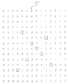
図1は、グリフマーク(絵文字)とこれらのグリフマーク内に具現化されたコードとを示す。グリフマークは基体24上のグリフマーク21等の基体上の繊細なパターンとして一般に実現される。グリフマークは肉眼では簡単に解像されない。従って、図1のグリフマーク21によって示されているように、グリフマークは一般に肉眼には一様なグレイスケールの外観又はテクスチャを有するものとして見える。
【0010】
拡大されたエリア23はグリフマーク21のエリアを示す。グリフマーク21は、グリフ22等の細長い斜線状のマークから成り、一般に、グリフの質量中心点から成るラティス(格子)上で幅方向及び長さ方向に均一に分散されて、矩形模様のグリフを形成する。グリフは通常前後に傾斜して、それぞれがバイナリ値「0」又は「1」を表す。例えば、基体24の長手方向のディメンションに対して+45°又は−45°傾斜していてもよい。これらのバイナリ特性を用いて、グリフマークは、特定のコーディング(符号化)システムを具現化する0と1を表す一連のグリフマークを生成するために使用され得る。グリフを0と1に復号化することによってグリフコードパターン25が生成される。グリフコードパターン25の0と1は、グリフマーク21を生成するために使用される特定のコーディングシステムに応じて更に復号化され得る。グリフが歪んだり消去されることによって生じる曖昧さを解消するために、復号化段階において更なる処理が必要になることもある。
【0011】
グリフマークは多くの方法で実現され得る。本発明による装置及び方法は、種々のタイプのグリフコードインプリメンテーションを読み取り、復号化する。例えば、グリフは、グラフィックと組み合わされることができ、又は、画像を生成するためのハーフトーンとして使用されてもよい。
【0012】
図2は、本発明によるグラフィックとグリフを組み合わせた画像210の実施の形態を示す。この特定の実施の形態において、グラフィックはユーザインターフェースアイコンを有する。各アイコンはグリフ上にオーバーレイしたグラフィックを有する。グリフはアドレスカーペットを形成する。このグリフアドレスカーペットは、グリフ値の適切なコーディングによって画像用の位置及び向きの固有(ユニーク)のアドレススペースを確立する。
【0013】
図3は、図2に示された画像210の一部の拡大図を示す。より詳細には、この部分212は、アドレスカーペットの一部とオーバーレイするLab.aviアイコンを示し、このアイコンは、アイコンのロケーション及び向きを曖昧に識別する。
【0014】
図4は、本発明によるグリフトーンを有する映像を示す。グリフトーンは、グリフコードを組み込んだハーフトーン画像を生成するために使用され得るエリア変調グリフを有する、ハーフトーンセルである。
【0015】
図5は、オーバーレイタイル状ラベルコードを有するグリフアドレスカーペットコードの一部の例を示す。uとvのグリフアドレスコードはアドレスカーペットを有し、dコードはオーバーレイタイル状ラベルコードを有する。この実施の形態において、uアドレスコードの行はvアドレスコードの行とインタリーブ(交互配置)されている。uアドレスコードの各行は、右下方向45°に走る斜線が一つ置きの行で同一uコードに沿って横切るように2位置ずれている。同様に、vアドレスコードの各行は、左下方向45°に走る斜線が一つ置きの行で同一vコードに沿って横切るように2位置ずれている。このuとvのアドレスコードの特性が、グリフのキャプチャ画像からのコード内の正確なロケーションを決定させる。
【0016】
6列(カラム)毎のアドレスカーペットはラベルコードを有するdコードに置き換えられる。ラベルコードはコンテクストのページ番号等の更なる情報を表す。図5におけるラベルコードはビットd01、d02、d03、及びd04から成る4ビットラベルコードである。dコードはアドレスカーペット全体を通して反復される。dコードはuとvのコードに代用される。例えば、最上段の行、v13、v19、v25、及びv31は、d03、d04、d01、及びd02にそれぞれ置き換えられる。各行において、6列毎のuとvのコードは、対応するdコードによってオーバーライト(上書き)される。アドレスカーペットのキャプチャされた部分において、dコードは情報を与えるラベルを提供するように復号化され得る。dコードは、例えば、ページ番号やコンテクスト情報を表すことができる。このように、図5に示されたグリフアドレスカーペットの部分がそれぞれ1100で表されるコードd03、d04、d01、及びd02と読み出された場合、再び順序付けられたdコードはd01、d02、d03、及びd04のコード、即ち、コード1100を形成し、ページ又はコンテクスト3(バイナリ0011=3)を示す。コードエレメント(即ちアドレッシング)の適切な論理的一致は、アドレスコードによって提供される。
【0017】
図5に示されるように、オーバーレイタイル状ラベルコードを有するグリフアドレスカーペットコードのキャプチャされた部分から、向き、ロケーション、及びラベルを決定することができる。以下に極めて詳細に説明されるように、uとvのアドレスコードは位置を決定するために使用することができ、dコードはラベル情報を提供する。
【0018】
本発明による装置及び方法は、基体から埋め込みデータを読み取り、この埋め込みデータを復号化して装置内の基準に対する基体の位置合わせを決定し、この位置合わせ情報に基づいた人間が知覚できる情報を展開させると共に提供する。一つの実施の形態において、人間が知覚できる情報は基体と位置合わせされたビジュアル(視覚)情報である。人間が知覚できる情報は、例えば、触感、可聴、又は他の知覚情報を有していてもよい。
【0019】
図6は、埋め込みデータを有する画像を読み取り、この画像内の埋め込みデータを復号化し、この復号化された埋め込みデータに基づいて人間が知覚できる情報を展開させるためのシステムを示す。より詳細には、画像キャプチャ470は埋め込みデータを有する画像をキャプチャするために基体468を読み取り、デコーダ472はキャプチャ画像内の埋め込みデータを復号化し、情報ジェネレータ474は復号化された埋め込みデータに基づいて人間が知覚できる情報を展開させるとともに、この情報を(一つ以上の情報出力デバイスを表す)情報出力476へ出力する。人間が知覚できる情報は、基体468と位置合わせされたビジュアルな情報であってもよいし、触感、可聴、又は他の人間が知覚できる情報等の他の人間が知覚できる情報を付加的又は代替的に有していてもよい。
【0020】
図7は、本発明によるエレメントの論理的構成を示すブロック図である。画像キャプチャデバイス70は基体68から画像をキャプチャする。基体68は、具現化されたグリフ等の埋め込みデータを上に有する。画像キャプチャデバイス70は、キャプチャされた基体画像をデコーダ72及び画像ジェネレータ74へ転送する。一つの実施の形態において、基体68上の埋め込みデータはアドレスカーペットとタイル状ラベルコードとを有する。デコーダ72は、キャプチャされた基体画像内の埋め込みデータを解析して、向き、ロケーション、及びラベル情報等の基体の位置合わせに関する情報を決定する。これらの結果は更なる処理のために画像ジェネレータ74へ転送される。
【0021】
画像ジェネレータ74は、デコーダ72からの結果と、画像キャプチャデバイス70からのキャプチャされた基体画像と、を処理する。一つの実施の形態において、画像ジェネレータ74は、デコーダ72から、コンテクストコード、ロケーションコード、及び回転コードを受け取る。コンテクストコードは基体ページ番号等の基体68の特定のコンテクストを定義付ける。ロケーションコードは、キャプチャ画像が取り出された基体68上のロケーションを定義付ける。回転コードは、画像キャプチャデバイスに対する基体の向きを提供する。コンテクストコードとロケーションコードを用いて、画像ジェネレータ74は、コンテクストコードとロケーションコードに関わる情報にアクセスする。例えば、コンテクストコードが基体ページivを表す場合、ロケーションコードは、ロケーション座標x=97及びy=92並びに回転角=43°を示し、画像ジェネレータ74は、対応する情報を検索し基体と位置合わせされる画像を生成する。回転コードは、生成された画像の向きを位置合わせすることを可能とする。
【0022】
一つの実施の形態において、検索された情報は、二つのタイプの情報、即ち、基体ページivのビットマップ画像表示の形態における画像情報と、基体ページiv上のアイコンのロケーション及び意味を定義付けるアイコン情報と、を含む。ユーザが選択したいとするディスプレイ76においてアイコンを観察する場合、この情報を用いて、ユーザは選択信号を提供することができる。これに応じて、従来のディスプレイにおけるユーザインタフェース上のアイコンのユーザ選択に応答して従来のシステムがするように、図7の位置合わせシステムに取付けられたシステム(図示せず)は、アイコンに対応するファンクション(機能)を実行するためにアイコンの検索された意味を用いることができる。
【0023】
検索された情報のサイズは変化し得る。一つの実施の形態において、画像ジェネレータ74は、ディスプレイ76のフットプリントと同じサイズであり、ディスプレイ76のフットプリントの真下で基体68のエリアに対応する、基体68の画像を検索する。ディスプレイ76が基体68のアライメントをとるので、ディスプレイ76を見ているオブザーバ78には基体68を直接見ているような錯覚が与えられる。画像ジェネレータ74は、情報を画像に追加してもよいし又はディスプレイ76へ送る前に検索された画像を変更してもよい。
【0024】
ディスプレイ76へ送られた画像は、画像ジェネレータ74によって多くの方法によって生成され得る。例えば、画像ジェネレータ74は、画像キャプチャ70によってキャプチャ画像を渡すだけでもよいし、画像キャプチャ70によってキャプチャ画像を表示するだけでもよい。例えば、基体68全体のビットマップ表示は画像ジェネレータ74内に局所的に又はネットワーク上の装置等の遠隔デバイス上に記憶されてもよい。一つの実施の形態において、デコーダ72からコードを受け取ることに応答して、画像ジェネレータ74は、ビットマップ表示からコードに対応するエリアを検索し、ユーザへディスプレイするためにディスプレイ76へにエリア表示を送る。画像ジェネレータ74によって検索されたエリア表示は、画像キャプチャ70によってキャプチャ画像と同じサイズであってもよいし、又は、キャプチャされたエリアの表示のみならずキャプチャされたエリア以外のエリアの表示も含む、拡大されたビューであってもよい。拡大ビューアプローチは、画像キャプチャ70に対して、コードが導出されるのに十分な大きさである基体68からの画像をキャプチャするのに必要とされる大きさになることを求め、しかも、より大きな領域を見ることの知覚をユーザに提供する。
【0025】
図8は、本発明によるシステムの実施の形態を示すブロック図である。埋め込みデータを上に有する基体89は、半透明のミラー82の下に位置決めされる。基体89からの画像は画像キャプチャデバイス80によってキャプチャされる。画像キャプチャデバイス80はキャプチャ画像をデコーダ88へ送り、デコーダ88は画像を復号化し、キャプチャ画像からコードを決定する。デコーダ88はコードを画像ジェネレータ84へ送る。画像ジェネレータ84はコードを処理し、これらのコードに基づいて画像情報を生成/検索し、この画像情報を半透明ミラー82へ送る。
【0026】
半透明のミラー82を見下ろすオブザーバ86は、基体89からの画像上にオーバーレイされる、画像ジェネレータ84によって生成された画像を見る。このように、オーバーレイされた情報は、ダイナミックに更新され、画像キャプチャデバイス80によってキャプチャされた復号化された画像に基づいて、基体89の情報へ位置合わせされ得る。
【0027】
他の実施の形態においては、画像キャプチャ80は半透明のミラー82から反射した基体画像を受け取る。
【0028】
図9は本発明によって組み立てられたシステムの他の実施の形態である。基体98からの画像は、半透明のミラー96から投影表面102へ反射される。基体98からの画像は、画像キャプチャデバイス90によってもキャプチャされる。画像キャプチャデバイス90は、この画像をデコーダ92へ転送し、デコーダ92は、画像を処理して、位置合わせ情報を復号化し、更なる情報を生成すべきか否かを判定する。その判定に基づいて、デコーダ92は信号を画像ジェネレータ94へパスして、画像ジェネレータ94が画像を生成するように仕向ける。画像ジェネレータ94が投影表面102へ投影される画像を生成する。投影表面102をビューするオブザーバ100は、画像ジェネレータ94によって生成された画像にオーバーレイされるとともと位置合わせされる基体98からの画像を見る。このシステムは基体98を照らするためのイルミネーションソース104を含んでいてもよい。
【0029】
図6、図7、図8、及び図9のシステムの各々において、エレメントは情報をネットワークデバイスに及び/又は同デバイスから送受信してもよい。これによってエレメントをネットワーク上のデバイスと対話させる。例えば、プログラム及びデータがネットワークデバイスからエレメントに送られてもよいし、これらのデバイスが情報をネットワーク上のデバイスに送ってもよい。
【0030】
図10は本発明による情報の位置合わせを示す図である。このプロセスは上述された装置によって実行されてもよい。基体364は、上に埋め込みコードが具現化され、三角形等の画像を有してもよい。埋め込みコードは、基体364上のx、yの位置が決定され得るコードシステムを具現化する。
【0031】
画像キャプチャデバイスは基体364の一部をキャプチャし、これによって基体上の埋め込みコードの一部の画像をキャプチャする。埋め込みコードは、埋め込みコード内のx、yのロケーションと、基体364上の十字矢印によって表される基体364の向きと、を決定するように復号化される。ラベルコードはキャプチャされた埋め込みコードから復号化されてもよい。
【0032】
このラベルコードに基づいて、画像情報366は記憶から検索される。次に、基体上で具現化された埋め込みコードから復号化されたx,yのロケーション情報と向き情報が基体364に画像情報366を位置合わせするために使用される。これらは複合画像368を形成するために使用されてもよい。
【0033】
図11は、本発明によるレンズ装置の実施の形態を示すブロック図である。レンズ装置328は、支持アーム330によって支持されるレンズビューポート334からなる。レンズビューポート334から見下ろすオブザーバは埋め込みコードを上に具現化させた基体332を観察する。カメラ(図示せず)は基体332の画像をキャプチャする。この画像はコンピュータ(図示せず)へ送られ、コンピュータは、レンズビューポート334の下に現れる基体332のx,yのロケーションと、レンズビューポート334の下の基体332の向きと、もしあれば、基体上に埋め込まれたコード内のラベルコードと、を復号化する。基体332のラベル、x、yのロケーション、及び向きに基づいて、コンピュータは、生成された画像情報が基体332と位置合わせされるようにレンズビューポート334にディスプレイされるオーバーレイ画像情報を生成する。位置合わせされたオーバーレイ画像は画像ジェネレータ(図示せず)によって投影される。
【0034】
図12は、図11に示されたレンズ装置の側断面図である。レンズ装置328は、カメラ392、ディスプレイ394、ランプ396、ディスプレイコントローラ398、コンピュータ400、及び半透明ミラー402を更に備える。ランプ396は、基体332(図示せず)を照らす。図7、図8、及び図9のそれぞれに示された画像キャプチャデバイス70、80、及び90に対応するカメラ392は、基体の画像をキャプチャし、画像をコンピュータ400に伝送する。コンピュータ400は、図7、図8、及び図9のそれぞれに示されたデコーダ72、82、及び92のファンクションを実行する。生成された画像は半透明のミラー402から反射されるので、コンピュータ400は、ディスプレイコントローラ398及びディスプレイ394に組み合わされて、図8に示される画像ジェネレータ84に最も類似したファンクションを実行する。
【0035】
コンピュータ400は、キャプチャ画像内の埋め込みデータを復号化してキャプチャ画像のx,yロケーションを決定し、x,yロケーションはレンズビューポート334下に現れる基体上のエリアのロケーションを表す。
【0036】
コンピュータ400は、キャプチャ画像内の埋め込みデータも復号化してレンズビューポート334下の基体332の向きと、もしあれば、キャプチャ画像の埋め込みコード内のラベルコードと、を決定する。この情報から、コンピュータ400はオーバーレイ画像情報を生成し、この情報は、ディスプレイコントローラ398に送られる。ディスプレイコントローラ398はこのオーバーレイ画像情報をディスプレイ394に送る。ディスプレイ394は、ディスプレイコントローラ398からのオーバーレイ画像情報に基づいてオーバーレイ画像情報を生成する。ビューポート334を通して見るオブザーバ390は、画像ジェネレータ394によって生成されたオーバーレイ画像情報がオーバーレイした半透明ミラー402を介して基体332を見る。
【0037】
図13は、基体、オーバーレイ画像、及び図11及び図12に示されたレンズビューポートから見たオーバーレイ画像がオーバーレイした基体、の例を示す。基体480は北米及び南米の画像並びに埋め込みデータとを有する。一つの実施の形態において、基体は全体的に埋め込みデータによって覆われる。ユーザは基体480をレンズビューポート334の下へ配置し、カメラ392はレンズビューポート334の下に現れる画像をキャプチャし、画像をコンピュータ400へ送信する。コンピュータ400は、基体480からキャプチャ画像内の埋め込みデータを復号化して、キャプチャ画像のx,yのロケーションを決定し、x,yのロケーションは、レンズビューポート334の下に現れる基体上のエリアのロケーションを表す。コンピュータ400は、キャプチャ画像内に埋め込まれたデータも復号化して、レンズビューポート334下の基体480の向きと、もしあれば、キャプチャ画像の埋め込まれたコード内のラベルコードと、を決定する。
【0038】
この情報から、コンピュータ400は、ディスプレイコントローラ398へ送られるオーバーレイ画像情報482を生成する。ディスプレイコントローラ398は、オーバーレイ画像情報482をディスプレイ394へ送る。ディスプレイ394は、レンズビューポート334を通して半透明のミラー402から反射する、オーバーレイ画像情報482を生成する。ビューポート334から見るオブザーバ390は、画像ジェネレータ394によって生成されるオーバーレイ画像情報482がオーバーレイした半透明のミラー402を通して基体332を見る。図13では、ユーザは北米にオーバーレイされたボーダを見る。
【0039】
図14は、基体と、オーバーレイ画像と、図11及び図12に示されたレンズビューポートから見たオーバーレイ画像がオーバーレイした基体と、の他の例を示す。より詳細には、図14は、レンズビューポート334下でユーザが基体430を移動するときのシステムが応答する方法を示す。この例において、基体430は、小文字“el”と“world”とを有する。基体430は、基体上に具現化された埋め込みデータ(図示せず)を有する。文字“e”がレンズビューポート334の下へ来るようにユーザが基体430を移動するとき、カメラ400はレンズビューポート334下の基体エリアの画像をキャプチャする。コンピュータ400は、基体430からキャプチャ画像内の埋め込みデータを復号化してキャプチャ画像のx,yのロケーションを決定し、このx,yのロケーションはレンズビューポート334下に現れる基体上のエリアのロケーションを表す。コンピュータ400は、キャプチャ画像内の埋め込みデータも復号化して、レンズビューポート334下での基体480の向きと、もしあれば、キャプチャ画像の埋め込まれたコード内のラベルコードと、を決定する。
【0040】
この情報から、コンピュータ400はオーバーレイ画像情報“H1”を生成し、“H1”はディスプレイコントローラ398に送られ、半透明のミラー402から反射する。レンズビューポート334から見るユーザは、図14の右上に示されるように、オーバーレイ画像情報“H1”がオーバーレイした“e”を見る。 “l”がレンズビューポート334の下へ来るようにユーザが基体430を移動するとき、カメラ392はレンズビューポート334下の新しいエリアの画像をキャプチャする。コンピュータ400は新しいエリア内の埋め込みデータを復号化し、ディスプレイコントローラ398へ送られる画像“o”を生成する。レンズビューポート334から見るユーザは、図14の右下に示されるように、オーバーレイ画像情報“o”がオーバーレイした“l”を見る。このように、ユーザが基体430を移動するにつれて、オーバーレイ画像情報がダイナミックに変更されてレンズビューポイント334内に現れる。より詳細には、レンズビューポート334の下に現れる基体430のエリアへの位置合わせを維持するようにオーバーレイ画像情報がダイナミックに変更される。
【0041】
図7、図8、図9、及び図12について説明されたシステムの各々は、画像情報を基体と位置合わせする。位置合わせするには、位置合わせしようとする情報の内容と基体に対する情報の向きを決定するために基体上の埋め込みデータを復号化することが必要とされる。従って、本明細書中に記述される復号化及び位置合わせの技術は、本発明による任意のシステムに適用され得る。
【0042】
オーバーレイ画像を基体と位置合わせするには、基体の向きを画像キャプチャデバイスに対して正確に決定することが必要とされる。画像キャプチャデバイスに対する向きの角度を決定するため、コンピュータ400は0°乃至360°の角度を解像する。これは2段階で行われる。第1に、格子軸から最も近いコードラント軸までのコードラントオフセット角(−45°乃至+45°)が決定される。第2に、0°、90°、180°、又は270°のコードラント角が決定される。コードラントオフセット角とコードラント角の合計が向きの角度である。
【0043】
図15は、画像を位置合わせするためにコンピュータ400によって実行される処理を示すフローチャートである。コンピュータ400はグリフの格子を含む基体の画像を最初にキャプチャし(ステップ130)、次に、グリフの格子のコードラントオフセット角を画像キャプチャデバイスに対して−45°乃至+45°と決定する(ステップ132)。コンピュータ400は次に画像内のグリフを0と1から構成されるデータになるように復号化する(ステップ134)。復号化されたデータから、コンピュータ400は、0°、90°、180°、又は270°のコードラント角を決定し、次に、ステップ133からのデータをアドレスカーペットを生成するために使用されるアドレスカーペットコードに相関させ、キャプチャ画像のx,yのロケーションを決定する(ステップ136)。コンピュータ400は、コードラントオフセット角とコードラント角を合計して、格子コードと画像キャプチャデバイスの間の向きの角度を決定する。
【0044】
コンピュータ400は、復号化されたデータからコンテクストコードも決定する(ステップ138)。コンテクストコードを用いて、コンピュータ400はコンテクスト専用オーバーレイを生成し(ステップ140)、コンテクスト専用のx,y,スケールと回転オフセット値とをオーバーレイに適用する(ステップ142)。最後に、コンピュータ400は、計算されたx,y及び回転値をオーバーレイへ適用し(ステップ144)、画像のディスプレイのための画像情報を生成する(ステップ146)。
【0045】
他の実施の形態において、グリフはコンテクストラベルを含まない。この実施の形態において、ステップ138は実行されず、画像情報の検索はロケーションコードのみに基づいて行われる。
【0046】
図16は、図17のフローチャートに応じて、グリフ格子画像内の重畳された近隣画像の中の画像を生成するプロセスをグラフィカルに示す。より詳細には、図16に示される実施の形態において、グリフ格子画像200の代表的な近接画像204、206、208、及び210が重畳されて、重畳された近接画像の複合画像202を形成する。複合画像202から、以下に詳細に記述されるように、コードラント角が決定される。
【0047】
図17は、コードラントオフセット角を決定する際に使用される複合格子画像を生成するためにコンピュータ400によって実行される処理を示すフローチャートである。コンピュータ400はカメラ392によってキャプチャ画像からシード画素を最初に選択する(ステップ162)。一つの実施の形態において、シード画素の選択はキャプチャ画像座標0、0で開始される。コンピュータ400は、シード画素の近傍に局所的な最小値を見つけ、グリフの存在を示す(ステップ164)。コンピュータ400は次にこのグリフの質量中心(面積の質量中心)を見つけ(ステップ166)、グリフがその直接周辺画素に対して(グリフが)確実に復号化されるのに十分なコントラストを有しているか否かを判定する(ステップ168)。グリフの質量中心は図19に関してより詳細に説明されている。コンピュータ400はサンプリング(抜き取り)の試みが既に多すぎたか否かを判定する(ステップ174)。サンプリングの試みが多すぎた場合、処理は失敗である(ステップ172)。多すぎなかった場合、前もって解析されたシード画素から特定のx及びyの間隔を置いて次のシード画素を解析のために選択することによって、ステップ162において処理が続行される(ステップ162)。特定のx及びyの間隔は複合画像の高さ及び幅に基づく。
【0048】
十分なコントラストがある場合(ステップ168)、コンピュータ400は、グリフ質量中心を原点として用いて、キャプチャ画像のサイズ(幅×高さ)のサブサンプルを複合画像へ付け足す(ステップ176)。コンピュータ400は次に十分なサンプルが抜き取られたかを判定する(ステップ178)。限定数を超えない場合、コンピュータ400はサンプリング回数が多すぎたか否かを判断する(ステップ170)。
【0049】
サンプリングの試みの限定数を超えた場合、コンピュータ400は複合画像の値をうまくいったサンプル数で割り算して、サブサンプル領域内の画素の平均値を決定する(ステップ180)。図18に示されるように、得られた複合画像から、コンピュータ400は、コードラントオフセット角を決定する(ステップ182)。コードラント角の正確度は、複合画像のサイズに比例する。他の方法としては、大きな複合画素の方が小さな複合画像より正確なコードラント角を提供する。
【0050】
図18は、図17のフローチャートに従って生成される複合格子画像を用いてコードラントオフセット角を決定するためにコンピュータ400によって実行される処理を示すフローチャートである。コンピュータ400は、グリフピッチに等しい原点からの距離、即ち、グリフの格子上の隣接するグリフ間の距離、においてゼロから90°の弧に沿って最も暗い画素を最初に見つけ(ステップ230)、次に、この画素を含む形状の中心を見つける(ステップ232)。中心が見つかると、コンピュータ400は格子の軸がこの中心と原点を通過すると仮定して、中心位置とグリフピッチに基づいた格子軸に沿って次の最小値の大体のロケーションを推定する(ステップ234)。この推定結果を用いて、コンピュータ400は、推定されたロケーション周辺の局所的最小値を見つけ(ステップ236)、その最小値を含む形状の質量中心を見つける(ステップ238)。複合画像のサイズに基づいて、コンピュータ400は格子軸に沿った可能性のある最後の最小値が見つかったか否かを判定する(ステップ240)。可能性のある最後の最小値が見つからかなった場合、ステップ234で処理を続行する。可能性のある最後の最小値が見つかった場合、コンピュータ400は原点から中心を介して、軸線と呼ばれる直線をフィットする(ステップ242)。コンピュータ400は、次に、軸線の角度を0°乃至90°の間で決定し(ステップ244)、次に、この角度は45°減らすことによって−45°乃至+45°の範囲内になるようにオフセットされる(ステップ246)。
【0051】
図19は本発明によるグリフの質量中心を見つけるための一つの方法をグラフィカルに示す。質量中心のY座標は、
【0052】
【数1】

質量中心のX座標は、
【0053】
【数2】
【0054】
【数3】
【0055】
図20及び図21は、図16に示されるように、複合画像の回転角を正確に決定するために複合画像を解析する方法を示す。複合画像のコードラントオフセット角は、適切な角度のコードラントの決定を条件として、オリジナルのキャプチャ画像内のグリフ格子の向きの正確な決定を表す。コードラントオフセット角と角度のコードラントとを組み合わせることによって、画像キャプチャデバイスと基体の相対角度が完全に決定される。図20はコードラントオフセット角が0°である一つの例を示し、図21はコードラントオフセット角が有限角度θである他の例を示す。
【0056】
本発明による装置及び方法は、本明細書中に参照することによって組み込まれる、1998年8月31日に出願された、"GLYPH ADDRESS CARPET METHODS AND APPARATUS FOR PROVIDING LOCATION INFORMATION IN A MULTIDIMENSIONAL ADDRESS SPACE(多次元アドレス空間における位置情報を提供するグリフアドレスカーペット方法及び装置)"(事件整理番号:07447.0010-00000)と題された、米国特許出願番号 に示されたものと同様のアドレスカーペットコード及び関連したプロセスを使用する。
【0057】
図22は、上述されたu及びvコードと同様のグリフアドレスカーペットの一部において符号化されたアドレスコードの実施の形態を示す。アドレスは「A」のアドレスコードシーケンスと「B」のアドレスコードシーケンスの行(ロー)を交互にすることによって符号化される。各行における各シーケンスに沿った位置は、所定の長さのサブシーケンスから明瞭に決定可能でなければならない。例えば、N―ビットのシフトレジスタ最大長コードはN―ビットのサブシーケンスからの位置で独特に決定され得る。各アドレスコードシーケンスは、Aシーケンスが左右にインデックス付けされ、Bシーケンスが、逆方向、即ち、右から左にインデックス付けされた15ビットのシーケンスである。Aコードシーケンスの各行は、Aアドレスの一つ前の行と一つ後の行に対する二つのグリフ位置分、オフセットされる。同様に、Bコードシーケンスの各行は二つの位置分、反対方向にオフセットされる。このように、符号化法には、二つのキー特性、即ち、2セットの1次元の固有のアドレスコードと、これらの2セットの中からの各ペアのオフセットが固有であるように二つのセットのメンバの中から選ばれる相対オフセットと、がある。これによって2次元の固有のアドレスロケーションが確立される。
【0058】
コンピュータ400は、2段階でキャプチャ画像エリアを解析することによってグリフ内で符号化されたアドレス情報を復号化する。理想的には、図7、図8、図9、及び図12に関して示されるとともに説明されているシステムにおいて、画像キャプチャデバイス70、80、90、及び392はそれぞれ図22に示されたビットパターンにおいて示されるように角度付けられてアライメントをとられた基体のエリアをキャプチャする。しかしながら、現実には、基体及び画像キャプチャデバイスは互いにアライメントをとられない。このように、二つの間の相対角は0°から360°までの範囲のどこに向けられてもよい。従って、コンピュータ400はアドレス情報を復号化すると共に解釈することの一部として画像の向きを最初に決定しなければならない。
【0059】
画像の向きはキャプチャ画像を解析することによって決定される。この処理は明瞭化と呼ばれる。明瞭化の一つの方法は本明細書中に参照することによって明確に組み込まれている、ヘックト(Hecht)他に与えられた、米国特許第5,521,372号に記述されている。画像の適切な向きを決定した後で、コンピュータ400はアドレスカーペット内の選択されたロケーションのアドレスを復号化する。本発明による、コンピュータ400によって実行される明瞭化及びアドレス復号化方法は以下により詳細に記述される。
【0060】
図23及び図24は、キャプチャ画像エリア上でコンピュータ400によって実行される例示的な明瞭化及びアドレス復号化プロセスを示すフローチャートを形成する。コンピュータ400は、グリフシードを見つけるためにアドレスカーペットのキャプチャされた部分を画像処理することによって明瞭化処理を開始する。グリフシードは、その周辺に読み取り可能なグリフを有する第一に識別されるグリフである。グリフシードが見つかると、グリフ格子はグリフシードの近傍を処理することによって決定され得る(付録A及び付録B参照)。グリフは、次に、1又は0として復号化され、グリフ格子の行に対応する行と列を有するバイナリデータマトリックス(行列)に埋め込まれる。向きもまた、90°及び180°の回転に対して不明瞭であることもある。
【0061】
図25は、画像キャプチャデバイスによってキャプチャされるグリフ格子から形成されるバイナリデータマトリックス(BDM)2310を示す。BDMにおけるロケーションはグリフ格子内のロケーションに対応し、これにより、BDMのサイズはグリフ格子のサイズに密接に対応する。
【0062】
グリフ格子の各ロケーションは、BDMの対応するロケーションにどの値が配置されるべきかを決定するために解析される。最初は、BDMは、このグリフを読み取る試みが全くなされなかったことを示す値、例えば、φでフィル(充填)される。特定のロケーションに対応するグリフが解析されると、φはグリフの解析結果を示す値によって置き換えられる。
【0063】
図25において、Bはボーダー位置を示し、Xはグリフ格子の対応する位置において解釈可能なグリフが見つからなかったことを示し、Eはキャプチャ画像部分のエッヂにおけるグリフを示し、0は後方向スラッシュグリフを示し、1は前方向スラッシュグリフを示し、dはラベルコードを示す。キャプチャ画像に対応するマトリックスのエリアは0及び1によってフィルされ、エッジはEによって境界付けられ、Xは読み取り可能なグリフをもたないロケーションに対応する。BDMは、図25と同様の全体的パターンを有するが、値は、しばしば、図25に示されるように、均一に分散されない。グリフが消去された場合、例えば、キャプチャ画像エリア内のグリフロケーションが結果的にXを生じることもある。いくつかの値は、反対方向に千鳥形の二つの分離したコードシーケンスを示すために周りが円や四角で囲まれていた。
【0064】
画像キャプチャデバイスは任意の角度で基体に対して方向付けされてもよい。
従って、キャプチャ画像は任意の角度で方向付けすることができる。このように、0及び1のBDMがキャプチャ画像から得られたとしても、BDMが、画像がキャプチャされたグリフアドレスカーペット内のオリジナルコードパターンに対して、0°(正確に方向付けられる)、90°、180°、又は270°で方向付けされるか否かは不明確である。キャプチャ画像の向きが決定されるまで、正確なアドレスコードをBDMから導出することは不可能である。向きは、物理的なシステムの制約などの補助的な情報によって提供され得る。しかしながら、向きはアドレスコードから直接、固有に決定され得る。
【0065】
グリフを0及び1に変換した後で、基準となるグリフロケーションが選択される(ステップ2211)。このロケーションは、多種多様な方法で選択することができるが、一般的には選択を表すロケーションである。例えば、基準となるグリフロケーションはBDMの中心であってもよい。
【0066】
画像は、BDMへ変換された後で、コンピュータ400によって処理される(ステップ2212)。キャプチャ画像から展開したオリジナルのBDMはBDM1と呼ばれる。コンピュータ400は、BDM1をコピーし、このコピーを時計回りに90°回転させて、第2のバイナリデータマトリックス、BDM2を形成する(ステップ2214)。BDM1を90°回転させることによって、BDM1の行がBDM2の列になり、BDM1の列がBDM2の行になる。さらに、90°回転した45°のスラッシュグリフが非回転グリフの反対の状態として現れるので、BDM2におけるすべてのビット値は0から1及び1から0へフリップされる。
【0067】
コンピュータ400は次にBDM1の奇数と偶数の行上で相関を別個に実行して(ステップ2216)、行におけるコードが前方に千鳥形になるか後方に千鳥形になるかを判定する。相関はBDM2の奇数と偶数の行に対しても実行される(ステップ2218)。相関は各BDMのすべての行に対して行なわれ、結果的に、BDM1に対しては相関値C1がBDM2に対しては相関値C2が生じる。
【0068】
図26は、図24の相関ステップ2216及び2218の実施の形態を示すフローチャートである。このプロセスは、各方向の対角線に沿ったBDMの一つ置きのラインに対して相関値を決定し、行相関値を合計して、奇数又は偶数の行に対する最終的な相関値を形成する。このプロセスは、BDM1の奇数行上で実行され、BDM1に対して相関値C1ODDを形成し、BDM1の偶数行上で実行され、BDM1に対して相関値C1EVENを形成し、BDM2の奇数行上で実行され、BDM2に対して相関値C2ODDを形成し、BDM2の偶数行上で実行され、BDM2に対して相関値C2EVENを形成する。0°又は180°において方向付けされたBDMは、他のBDMより大きなCODD+CEVENを有する。
【0069】
コンピュータ400はBDMを最初に入力し(ステップ2410)、次に一つ置きの行を仮マトリックスにコピーする(ステップ2412)。次に、同一プロセスが右方向及び左方向の対角線に対して実行される。ステップ2414、ステップ2416、ステップ2418、ステップ2420、ステップ2422、及びステップ2424が対角線を右に処理する。例えば、図27において、ステップは左上から右下へ移動する対角線に沿って相関する。まず最初に、行カウントN個及び相関値C RIGHTはそれぞれゼロに初期化される(ステップ2414)。行Nは2位置右にシフトされ、次のローと相関される(ステップ2416)。C Nは次にこの値にセットされる(ステップ2418)。C RIGHTは次にC RIGHT+C Nにセットされ(ステップ2420)、Nがインクリメント(増分)される(ステップ2422)。行カウントN>=Nmax(NはBDM内の奇数及び偶数の行の数である)の場合、プロセスはステップ2426へ進む。NがNmax以下である場合、処理はステップ2416で続行される。このように、処理が各隣接行を相関した後、相関値C RIGHTは右側の対角線に沿った相関の強度を示す。
【0070】
図26の右側のステップは、ステップ2414,ステップ2416、ステップ2418、ステップ2420、ステップ2422、及びステップ2424と同様であるが、相関値C LEFTを展開させるために右上から左下へ走る対角線を処理する。C RIGHT及びC LEFTを決定するために右と左の対角線を相関した後、最終相関値CがC RIGHTからC LEFTを減算することによって決定される。例えば、BDM1に対する奇数の行が処理される場合、C値はBDM1に対するC1ODDとなる。
【0071】
図26の処理ステップは、BDM1の奇数と偶数の行及びBDM2の奇数と偶数の行に対して行われる。この情報から、(BDM1の行に対して図26によって決定されるように)BDM1に対する相関値C1がC1EVEN+C1ODDにセットされ、(BDM1の行に対して図26によって決定されるように)BDM2に対する相関値C2がC2EVEN+C2ODDにセットされる。
【0072】
図27は、相関が一つ置きの行のコードがどの方向にシフトしているかをどのようして判定するかを示す。例えば、右側に走る対角線に沿った○で囲んだA1によって示されるように、第2の行の最初の位置のA1から始まる対角線に沿ったコードは、消去及びエラーを除いて、対角線に沿った一つ置きの行において同一の値を有する必要がある。同様に、ボックスで囲んだB1によって示されるように、上部右コーナーのB1から始まる対角線に沿ったコードは、消去及びエラーを除いて、対角線に沿った一つ置きの行において同一の値を有する必要がある。このことは、最上段の行のB2、B3、...B15のそれぞれから走る奇数行の対角線に沿った各値にも当てはまる。このように、奇数行上で下の左方向に走る対角線に沿った強力な相関と偶数行上で下の右方向に走る対角線に沿った強力な相関は、偶数行のコードが右側へシフトしており、奇数行におけるコードが左側へシフトしていることを示す。
【0073】
これにより、各BDMに対して、四つの相関値、即ち、1)右から左へ奇数行、2)左から右へ奇数行、3)右から左へ偶数行、4)左から右へ偶数行、が得られる。これらの相関値から、偶数行に対する最強の相関値と、奇数行に対する最強の相関値とが選ばれ、これらの値がBDMに対するCEVEN+CODDとなる(ステップ2216及びステップ2218)。次に、CEVEN+CODDが加算されて、そのBDMに対する最終C相関値を形成する。ステップ2220に対しては、上述されたように、最強の相関値を有するBDMとは、奇数行及び偶数行のコードの相対的な向きのために0°又は180°のいずれかに方向付けられるBDMである。従って、選ばれたBDMの二つの面がここで設定される。即ち、一つ置きのラインのコードがどの方向に千鳥状とされることと、BDMが0°又は180°のいずれかに水平に方向付けされることである。ステップ2230においては、(どの方向にコードが千鳥状になるかとは反対に)他の相関処理が、各ラインのコードがどの方向へ走るかを判定するために実行される。
【0074】
奇数ラインにおけるコードは一つの方向に千鳥状となり、偶数ラインにおけるコードは他の方向に千鳥状となる。奇数ライン及び偶数ラインに走るそれぞれのコードを知ることに関連して、コードの千鳥形特性によってBDMの適切な0°の向きが決定される。
【0075】
図23に戻ると、C1がC2より大きい場合(ステップ2220)、BDM1は更なる処理のために選択される。C1がC2より大きいということは、BDM1の1次元のコードが最も強く相関し、これによって、0°又は180°のいずれかに方向付けられることを示す(ステップ2222)。C2がC1より大きい場合、より高い相関は、BDM2が0°又は180°のいずれかに方向付けられることを示すため、BDM2は更なる処理のために選択される(ステップ2224)。このようにして、正確なBDMが発見された。キャプチャ画像のアドレスロケーションを決定する前に、しかしながら、コンピュータ400は、選択されたBDMが0°(即ち、正しい向きである)か、又は180°回転しているか否かをまず判定しなければならない。
【0076】
図24は、コンピュータ400がグリフカーペットのキャプチャされたエリアのアドレスを決定するステップを示すフローチャートである。好ましくは、BDMが0°に方向付けされた時、BDM内の対角線に沿ったビット位置は、一つ置きの行で同じ値を有する。しかしながら、画像キャプチャ処理とビジュアルインデックス及び置換ラベルコードdからの干渉とによって、BDMデータ内にエラーと消去が生じてしまう。これらのエラーと消去の衝撃を低減するため、コンピュータ400は奇数行が千鳥状である方向で各対角線に沿った奇数行に対して多数決を実行し、偶数行が千鳥状である方向において各対角線に沿って各行に対して多数決処理を反復する(ステップ2225)。これによって、奇数行に対して、第1のコードシーケンスが生じ、偶数行に対して、第2のコードシーケンスが生じる。多数決が正確に各ビット位置を決定する範囲で、第1と第2のコードシーケンスは、奇数又は偶数セットの行にそれぞれ対応するオリジナル擬似ノイズアドレスシーケンスと整合しなくてはならない。
【0077】
コンピュータ400は、前方に千鳥状になった行に対して、オリジナル擬似ノイズアドレスコード(Get Code 1)を検索し(ステップ2226)、後方に千鳥状になった行に対して、オリジナル擬似ノイズアドレスコード(Get Code 2)を検索する(ステップ2228)。各コードセットA及びBに対するオリジナル擬似ノイズアドレスコードと、多数決からのコードと、を用いて、コンピュータ400は四つの相互相関を実行して(ステップ2230)、奇数及び偶数行に対するPNシーケンスロケーションに対してのグリフシーケンスの最高の整合を設定する。
【0078】
より詳細には、ステップ2211において選ばれた基準エレメントに最も近いBDMの二つの隣接する行がオリジナルアドレスカーペットを作成したそれぞれの完成したPNシーケンスと関連付けられる。PNシーケンスは同一であってもよい。前方及び後方の相関が各行に対して実行される。四つの相関は、四つのペアのピーク相関及び位置の値を生じる:
1)P1及びV1のそれぞれは、ピーク相関値を表し、完全なPNシーケンスに後方相関されたコード1のための位置に対応する。
2)Q1及びU1のそれぞれは、ピーク相関値を表し、完全なPNシーケンスに前方相関されたコード2のための位置に対応する。
3)P2及びV2のそれぞれは、ピーク相関値を表し、完全なPNシーケンスに前方相関されたコード1のための位置に対応する。
4)Q2及びU2のそれぞれは、ピーク相関値を表し、完全なPNシーケンスに後方相関されたコード2のための位置に対応する。
【0079】
i=1又は2である、ピークの大きさに対応する、Ui及びViの位置の値が、ステップ2211において選ばれた基準エレメントに対応するX及びYの値を決定するために使用される。このように、(P1+Q1)>(P2+Q2)(ステップ2232)の場合、U1及びV1は、ステップ2211で選択された基準グリフロケーションのX、Yの位置を計算するために使用される(ステップ2236)。(P1+Q1)<=(P2+Q2)(ステップ2232)の場合、U2及びV2は、ステップ2211で選択された基準グリフロケーションのX、Yの位置を計算するために使用される(ステップ2234)。アドレス情報は以下の等式に従って決定される:
X=(Vi−Ui+全コードの長さ)/2
Y=(Vi+Ui−全コードの長さ)/2
【0080】
次に、計算されたX、Yの位置を戻す(ステップ2238)。対角線がU及びVそれぞれの一定値に対応する一方、行及び列が一定値X及びYに対応することに注目されたい。U及びVがアドレスパラメータとして直接使用されることも注目されたい。
【0081】
このように、ステップ2211において選択された基準点に関連付けられたX、Yの値が、決定される。この情報を用いて、コンピュータ400は、X、Yの座標を、論理基準、論理基準及びコントロール信号の組み合わせ、又は実行される特定の演算に、関連付ける。例えば、X、Yの座標は、コンピュータ400の指示下でコンピュータ400又は他のデバイスによって実行可能な演算の表になるインデックス(索引)として使用することができる。X、Yの座標は、アドレススペース内のX、Yの座標近くに位置するアイコンに関連付けられるファイルオープンコマンドに関連付けられてもよい。実際には、コンピュータ400によって行われる任意の演算は、特定のX,Y座標又はX,Y座標の範囲と関連付けられてもよい。
【0082】
図28は、画像キャプチャデバイスと基体との間に所定値V以下の速度において相対モーション(運動)がある時に連続画像キャプチャが画像キャプチャデバイスから処理されるときの迅速な処理のための方法を示す。最初に、第1の画像がキャプチャされ、ロケーションNo.1のロケーション座標を決定するために全体のアドレススペースが上記の教示に従って探索される。図28に示される例において、ロケーションNo.1は座標値u16、v22を有する。モーション速度がVより小さく、時間Tがキャプチャとキャプチャの間である場合、次のキャプチャはロケーションNo.1の座標周辺の半径R=VTの円内に制約される。従って、ロケーションNo.2を示す相関最大値を探索して使用されるインデックスの範囲は、ロケーションNo.1の座標周辺の半径Rの円内のロケーションのインデックス範囲ui、vjに限定され得る。好適な相関ピークが見つからない場合、処理は全体のアドレススペースの探索に戻る。好適な相関ピークが見つからないということはモーションが円の外へ飛び出したか又は基体が変更されたことを示すものである。
【0083】
この方法が、情報の抽出処理を迅速にし、実時間でのフレームツーフレームの画像キャプチャ等のアプリケーションを可能とすることができる。これは円滑化されたモーションディスプレイ及びジェスチュアモーションキャプチャに使用され得る。
【0084】
図29は、グリフアドレスカーペット1732等のグラフィカルユーザインタフェースのユーザ選択部分をキャプチャし、キャプチャされた部分におけるグリフを復号化するために使用され得る、ユーザインタフェース画像キャプチャシステムのブロック図である。一つの実施の形態において、コンピュータシステム1712は、従来のパソコン又はラップトップコンピュータ等の汎用目的のコンピュータシステムであり、メインメモリ1716、リードオンリーメモリ(ROM)1718、記憶デバイス1720、プロセッサ1722、通信インターフェース1724を含み、これら全てがバス1726によって相互接続されている。バス1726は、位置合わせされた画像システム1754、カーソルコントロール1714、及びフレームキャプチャ1728にも接続される。
【0085】
位置合わせされた画像システム1754は、図7、図8、図9、及び図12に関して示され説明されているように原則を具現化するシステム又は本発明の原則に従った他の位置合わせされた画像システムから構成されてもよい。例えば、図12の位置合わせシステム328は、図12のコンピュータ400としてのコンピュータシステム1712を用いて図29のシステムと共に実現されてもよい。フレームキャプチャ1728は位置合わせされた画像システム1754からキャプチャ画像を受け取り、キャプチャ画像をプロセッサ1722へ提供する。プロセッサ1722は、上述されたように、x、yロケーション、ラベル、向き情報等の情報を決定するために画像内の埋め込みデータを復号化し、復号化された情報に基づいて、画像情報を、位置合わせされた画像システム1754へ送る。位置合わせされた画像システム1754は、プロセッサ1722からの画像情報に基づいて、基体と位置合わせされる画像を生成する。
【0086】
位置合わせされた画像システム1754は、図29に示された他のデバイスから情報を受け取り、この情報をこれらのデバイスへ伝送してもよい。これによって、例えば、ネットワーク上の他のデバイスが、位置合わせされた画像システム1754と対話することができる。
【0087】
カメラペン1710とマウス1752は、位置合わせされた画像システム1754の演算とともに、コントロール信号をプロセッサ1722へ提供することができる。更に、ユーザインタフェース基体1732は、位置合わせされた画像システム1754が画像を(基体から)キャプチャする基体として使用され得る。
【0088】
カメラペン1710は、フレームキャプチャ1728及びマウス1752に接続され、補助ポインティングデバイスとして動作する。カメラペン1710は画像情報をフレームキャプチャ1728へ伝送する。一つの実施の形態において、カメラペン1710のボタン1714がマウス1752に配線されることによって、ユーザがボタン1714を押すと、信号がマウス1752の回路を介してカーソルコントロール1714へ移動する。信号は、プロセッサ1722にフレームキャプチャ1728を指示するプログラムを実行させてカメラペン1710から画像をキャプチャする。他の実施の形態において、カメラペン1710からの画像ラインと信号ラインは共にフレームキャプチャ1728に直接入力される。カメラペン1710とコンピュータ1712の間のラインはカメラペン1710から画像をキャプチャする任意の方法で配線され得る。
【0089】
ユーザは、グリフアドレスカーペット1732上のビジュアルインデックス上又はその近くにカメラペン1710を置き、ボタン1714を押すことによって選択する。ボタン1714を押すことによって、カメラペン1710が、カメラペン1710の先端下のアドレスカーペット1732の部分をキャプチャし、フレームキャプチャ1728を介して、解析のために画像をコンピュータ1712へ伝送する。ボタン1714又は複数のボタンは、ダブルクリック、ホールドダウンしながら、更なる信号送信のために使用されてもよい。
【0090】
コンピュータ1712は、LAN(ローカルエリアネットワーク)1734に接続されたデバイスと通信するためにLAN1734にも接続されている。例えば、LAN1734は、コンピュータ1740、プリンタ1736、及び大容量記憶装置1738に接続されてもよい。LAN1734はまた、他のネットワーク1744に接続されるようにゲートウェイ1742に接続されてもよい。ネットワーク1744は、コンピュータ1746、プリンタ1748、及びデータベース1750に接続されてもよい。コンピュータ1712をLAN1734及びネットワーク1744に接続することによって、コンピュータ1712はこれらのネットワークに接続されたデバイスを用いて、演算を実行することができる。例えば、カメラペン1710又はマウス1752によって選択されたプリント用ドキュメントはプリンタ1736又はプリンタ1748上でプリントされ得る。同様に、ユーザはコンピュータ1712を使用してデータベース1750上にファイルを要求してもよい。
【0091】
一つの実施の形態において、メインメモリ1716は、プロセッサ1722によって実行される命令を記憶するランダムアクセスメモリ(RAM)又は動的記憶装置である。メインメモリ1716は、命令を実行する際に使用される情報を記憶することもある。ROM1718はプロセッサ1722によって使用される静的情報及び命令を記憶するために使用される。磁気又は光学ディスク等の記憶デバイス1720はコンピュータシステム1712の演算に使用される命令及びデータも記憶する。
【0092】
ディスプレイ1730はCRT又は他のタイプのディスプレイデバイスであってもよい。カーソルコントロール1714はディスプレイ1730上のカーソルの動きをコントロールする。カーソルコントロール1714は、例えば、マウス、トラックボール、又はカーソル方向キーであってもよい。
【0093】
図29に示されるシステムは、本明細書中に記載されているグリフアドレスカーペットキャプチャ及び変換システムを実施するために使用され得る。本明細書中に記載されている装置及び方法は、ハードウェア、ソフトウェア、又はこれらの組み合わせを用いてコンピュータシステム1712によって実現されてもよい。例えば、本明細書中に記載されている装置及び方法は任意の一つ又はそれ以上のメインメモリ1716、ROM1718、又は記憶デバイス1720においてプログラムとして実現されてもよい。一つの実施の形態において、プロセッサ1722は、グリフ内で符号化されたアドレス情報を決定するためにグリフアドレスカーペットのキャプチャされた部分を解析するプログラムを実行する。
【0094】
このようなプログラムは、記憶デバイス1720等の他のコンピュータ読取り可能媒体からメインメモリ1716へ読み込まれる。メインメモリ1716内に含まれる命令のシーケンスの実行によって、本明細書中に記載されている本発明による処理ステップをプロセッサ1722に実行させる。メインメモリ1716内に含まれる命令のシーケンスの実行によって、また、プロセスステップを実行する装置エレメントをプロセッサ1722に実現させる。本発明を実現するため、ハードワイアリングされたサーキットリ(回路)は、ソフトウェアの命令の代わりに又はソフトウェアの命令と組み合わされて使用されてもよい。このように、本発明の実施の形態は、ハードウェアのサーキットリ及びソフトウェアの任意の特定の組み合わせに限定されるものではない。
【0095】
本明細書中に使用されているように、用語「コンピュータ読取り可能媒体」は、実行のためにプロセッサ1722に命令を提供する際に参加する任意の媒体をいう。このような媒体は、非揮発性メモリ媒体、揮発性メモリ媒体、及び伝送媒体を含むがこれらに限定されない多くの形態を取る。非揮発性のメモリ媒体は、例えば、記憶装置1720等の光学又は磁気ディスクを含む。揮発性メモリ媒体は、メインメモリ1716等のRAMを含む。伝送媒体は、バス1726を有するワイヤを含む、同軸ケーブル、銅製ワイヤ、ファイバ光軸を有する。伝送媒体は、無線波及び赤外線データ通信中に発生する、例えば、音響又は光波の形態を取ることもできる。
【0096】
コンピュータ読み取り可能媒体の共通の形態は、例えば、フロッピーディスク、フレキシブルディスク、ハードディスク、磁気テープ、又は任意の他の磁気記憶媒体、CD−ROM、任意の他の光学媒体、パンチカード、紙テープ、穴のあいた任意の他の物理的媒体、RAM、PROM、EPROM、FLASH−EPROM、任意の他のメモリチップ又はカートリッジ、以下に記述されるようなキャリアウェーブ、又はコンピュータが読み取り使用することができる任意の他の媒体を含む。
【0097】
種々の形態のコンピュータ読取り可能な媒体は、プロセッサ1722への実行のための命令の一つ以上のシーケンスを実行する際に係り合うことがある。例えば、命令は、磁気ディスク又は遠隔コンピュータ上で最初に実行されてもよい。遠隔コンピュータは、命令をその動的メモリへロードし、モデムを用いて電話回線を通じ、これらの命令を送ることができる。コンピュータシステム1712に局所的なモデムは、電話回線上でデータを受け取り、このデータを赤外線信号へ変換するために赤外線トランスミッタを使用することができる。適切なサーキットリに連結された赤外線検出器は、赤外線信号から送られたデータを受け取り、バス1726上にデータを置くことができる。バス1726は、プロセッサ1722が命令を検索し実行するメインメモリ1716へデータを送る。メインメモリ1716によって受け取られた命令は、プロセッサ1722による実行の前又は後のいずれかで、記憶装置1720上に選択的に記憶されてもよい。
【0098】
コンピュータシステム1712はまたバス1726に連結された通信インターフェース1724を含む。通信インターフェース1724は他のシステムに対して二方向通信を提供する。例えば、通信インターフェース1724は、対応する種類の電話回線へのデータ通信接続を提供する総合サービスディジタルネットワーク(ISDN)のカード又はモデムであってもよい。通信は、例えば、LAN(ローカルエリアネットワーク)へ通信を提供するためのLANであってもよい。通信インターフェース1724はまた、コンピュータシステム1712とワイアレスシステムとの間でワイアレス通信を実施するためのワイアレスカードであってもよい。任意のこのような実施の形態において、通信インターフェース1724は、種々のタイプの情報を示すデータストリームを運ぶ、電気的、電磁的、又は光学的信号を送受する。
【0099】
通信インターフェース1724と外部デバイス及びシステムとの間のリンクは、一般的に、一つ以上のネットワーク又はは他のデバイスを介してデータ通信を提供する。例えば、リンクは、ホストコンピュータや、インターネットサービスプロバイダ(ISP)によって操作されるデータ装置へのローカルネットワーク(図示せず)へ接続を提供してもよい。ISPは、現在は一般的に「インターネット」と呼ばれる全世界規模のパケットデータ通信ネットワークを介してデータ通信サービスを提供する。ローカルネットワークとインターネットは共に、ディジタルデータストリームを運搬する電気的、電磁的、又は光学的信号を使用する。コンピュータシステム1712に対してディジタルデータを送受する、種々のネットワークを介した信号、及びネットワークと通信インターフェース1724の間の信号の代表的な形態は情報をトランスポートするキャリアウェーブの形態である。
【0100】
通信インターフェース1724と外部システム及びデバイスとの間のリンクを介したネットワークを通じて、コンピュータシステム1712は、プログラムコードを含むメッセージを送りデータを受け取ることができる。例えば、インターネットにおいて、サーバは、インターネット、ISP、ローカルネットワーク、及び通信インターフェース1724を介してアプリケーションプログラムに必要とされるコードを伝送する。
【0101】
ネットワーク上で受け取られたプログラムコードはそれが受け取られた際にプロセッサ1722によって実行されてもよいし、及び/又は、後からの実行のために記憶デバイス1720等のメモリ内に記憶されてもよい。この方法において、コンピュータシステム1712は、キャリヤウェーブの形態でアプリケーションコードを得ることもできる。
【0102】
図30は、本発明による画像位置合わせシステムの他の実施の形態を示す。カメラマウス118は、カメラマウスボタン110、112、及び114及び信号ケーブル120を有する。カメラマウス118におけるマイクロカメラ(図示せず)はカメラマウスボタン110、112、及び114のうち、一つ以上を起動させるオブザーバに応答して、ターゲットエリアインジケータによって定義付けられる基体122のエリアをキャプチャする。マイクロカメラによってキャプチャ画像は、処理エレメント(図示せず)によってマウス118内で局所的に処理されるか、又は、カメラマウス118に取付けられたデバイス内の処理エレメントによって処理するために信号ケーブル120へ送られる。
【0103】
基体122は基体上に具体化された埋め込みデータを有するので、画像内にキャプチャされた埋め込みデータは復号化され得る。このように、カメラマウス118によってユーザが基体122の特定のエリア上にカメラマウス118を置き、次に、ディスプレイ150内にディスプレイされる、基体122のエリアの画像をキャプチャすることができる。キャプチャ画像内の埋め込みコードは、処理エレメントによって復号化され、復号化された情報が展開される。復号化された情報は、基体についてのコンテクスト、ロケーション、及び/又は向き等のいずれかを表す。処理エレメントは、復号化された情報を解析し、復号化された情報及びボタンコントロールに基づいて演算を実行するか、又はコード及びボタンコントロールをシンタックス(構文)キューに入れて、更なるコード及びボタンコントロールを待機する。
【0104】
復号化された情報に基づいて、画像情報が生成され、ディスプレイ150上に画像としてディスプレイされる。いくつかのタイプの画像情報がディスプレイされてもよい。例えば、その情報は、マイクロカメラ134によってキャプチャされた実際の画像、キャプチャ画像の表示、キャプチャ画像に関する他の情報以外でキャプチャされた実際の画像、又はキャプチャ画像のないキャプチャ画像に関する単なる情報、を有していてもよい。一つの実施の形態において、基体の表示は、検索され、キャプチャ画像に組み合わされて、ディスプレイ150上に複合画像を形成し、この複合画像は、キャプチャ画像とこのキャプチャ画像を囲む拡大されたエリアを示す。
【0105】
ディスプレイ150は、重畳された十字線を有するキャプチャ画像である、デビッドドキュメント(David's Document)アイコンを示す。ディスプレイ150はまたそのアイコンがユーザによって選択されたことを示すDavid's Document画像250を示す。例えば、ユーザがマウスをDavid's Document上に置く場合、マウスは基体122からDavid's Document画像をキャプチャし、キャプチャ画像をディスプレイ150上にディスプレイする。次にユーザがアイコンを選択するためにマウスボタンを起動させる場合、David's Documentアイコンの表示がDavid's Documentアイコン250としてディスプレイ150内にディスプレイされる。
【0106】
図31は、カメラマウス118の切断側面図を示すブロック図である。カメラマウス118は、マイクロカメラ134とXYモーションセンサ136とイルミネータ152と処理エレメント138とを含む。処理エレメント138はXYモーションセンサ136からの信号とマイクロカメラ134からの画像とを処理する。他の実施の形態においては、XYセンサ136を取り除いてもよい。
【0107】
マイクロカメラ134は半透明のミラー166から反射した基体122の画像を受け取る。ディスプレイ150上の画像をビューするオブザーバ130は、カメラマウスボタン110、112、又は114のうち、一つ以上を押すことによって画像をキャプチャしてもよい。マイクロカメラ134によってキャプチャされた基体122のエリアは、処理エレメント138によって処理される。図31はマウス118内に位置する処理エレメント138を示すが、処理の全体又は一部が信号ケーブル120によってカメラマウス118に接続された処理エレメントによって外的に実行されてもよい。
【0108】
開示されている実施の形態の明細書及び実施から考慮して、本発明の他の実施の形態は、当業者に明白である。明細書及び実施例は例示のみを目的としており、本発明の真の範囲及び精神は以下の請求項及びそれらと等価のものによって定義付けられる。
【図面の簡単な説明】
【図1】グリフマークとグリフマーク内に具現化されたコードの特性を示す概略図である。
【図2】本発明によるグラフィックとグリフを組み合わせた画像の実施の形態を示す図である。
【図3】図2に示された画像の一部を示す拡大図である。
【図4】本発明によるグリフトーンを有する描画用画像を示す図である。
【図5】オーバーレイタイル状ラベルコードを有するグリフアドレスカーペットコードの一部の例を示す図である。
【図6】埋め込みデータを有する画像を読み取り、画像内の埋め込みデータを復号化し、復号化された埋め込みデータに基づいた人間が知覚できる情報を展開するためのシステムを示す図である。
【図7】本発明によるエレメントの論理的構成を示す図である。
【図8】本発明によるシステムの他の実施の形態を示す図である。
【図9】本発明によって組み込まれたシステムの他の実施の形態を示す図である。
【図10】本発明による情報の位置合わせを示す線図である。
【図11】本発明によるレンズ装置の一つの実施の形態を示すブロック図である。
【図12】図11に示されたレンズ装置の切断側面図である。
【図13】図11及び図12に示されたレンズビューポートから見た、基体、オーバーレイ画像、及びオーバーレイ画像がオーバーレイした基体の実施例を示す図である。
【図14】図11及び図12に示されたレンズビューポートから見た、基体、オーバーレイ画像、及びオーバーレイ画像がオーバーレイした基体の他の実施例を示す図である。
【図15】画像を位置合わせするためにコンピュータ400によって実行された処理を示すフローチャートである。
【図16】図17のフローチャートに従って、グリフ格子画像内の重畳された近接画像のうちの一つの画像を生成する処理をグラフィカルに示す図である。
【図17】格子画像を用いてコードラントオフセット角度を決定するためにコンピュータによって実行される処理を示すフローチャートである。
【図18】複合格子画像を用いてコードラントオフセット角度を決定する際に使用される複合格子画像を生成するためにコンピュータによって実行される処理を示すフローチャートである。
【図19】グリフ質量中心を見つけているところを示す図である。
【図20】図16に示されているように、複合画像の回転角度を正確に決定するために複合画像を解析しているところを示す図である。
【図21】図16に示されているように、複合画像の回転角度を正確に決定するために複合画像を解析しているところを示す図である。
【図22】グリフアドレスカーペットの一部において符号化されたアドレスコードの実施の形態を示す図である。
【図23】コンピュータによって実行される明確化及びアドレス復号化処理を示すフローチャートを形成する図である。
【図24】コンピュータによって実行される明確化及びアドレス復号化処理を示すフローチャートを形成する図である。
【図25】グリフ格子から形成されたバイナリデータマトリックスを示す図である。
【図26】図24の相関ステップの実施の形態を示すフローチャートである。
【図27】一つ置きの行におけるコードがずれる方向を相関がどのように決定するかを示す図である。
【図28】連続キャプチャが画像キャプチャデバイスから処理されるときの優先処理のための方法を示す図である。
【図29】グラフィカルユーザインターフェースのユーザ選択部分をキャプチャするために使用され得るユーザインターフェース画像キャプチャシステムを示すブロック図である。
【図30】本発明による画像位置合わせシステムの他の実施の形態を示すブロック図である。
【図31】カメラマウスの切断側面を示すブロック図である。
【符号の説明】
21 グリフマーク
22 グリフ
23 拡大領域
24 基体
25 グリフコードパターン[0001]
BACKGROUND OF THE INVENTION
The manufacturing apparatus, the manufacturing method, and the product according to the present invention generally relate to the spatial alignment (registration) of information, and more particularly capture an image of the first information with embedded data, The present invention relates to decoding embedded data in the captured image, retrieving second information based on the decoding, and spatially aligning the second information with the first information.
[0002]
[Prior art]
It is often useful to align the first set of information with the second set of information. For example, augmented reality (actual) is realized by generating a composite view of physical reality aligned with computer-generated information about physical reality. In the augmented reality system, the first set of information, such as the physical reality image, may be aligned with the second set of information, such as information about the physical reality image.
[0003]
One conventional method for creating augmented reality is to capture an image of a physical scene, identify an object in this scene using a scene recognition algorithm, and retrieve information based on the identified object. The physical scene is augmented by generating a display that combines the image of the physical scene with information about the identified object. One drawback of such a system is that a large amount of processing is required to perform the scene recognition algorithm, especially when the system has to differentiate many different objects in a scene to identify the location of the object in this scene. The ability is needed. By identifying the location of the object, the retrieved information is placed at a location in the composite display that is aligned with the identified object. The retrieved information is “aligned” by spatially associating the retrieved information with the identified object. Another drawback is that general and registration cannot be determined from a partial capture of the scene.
[0004]
[Problems to be solved by the invention]
What is needed is a system that can align the first information and the second information without the limitations of conventional systems.
[0005]
[Means for Solving the Problems]
A manufacturing apparatus, a manufacturing method, and a product according to the present invention have an alignment scheme in which a first set of information on a substrate embodying embedded data is aligned with a second set of information based on the embedded data. I will provide a. According to this alignment scheme, the image capture device captures an image that includes the embed code and generates a display that includes a combination of the captured image and information that augments the image with additional information. This further information is aligned with the captured image in the combined display.
[0006]
Additional objects and advantages of the present invention will be set forth in part in the description which follows, and in part will be apparent from the description, or may be learned by practice of the invention. The objects and advantages of the invention will be realized and attained by means of the elements and combinations particularly pointed out in the appended claims. It will be understood that both the foregoing general description and the following detailed description are for purposes of illustration and description only and are not intended to limit the invention as set forth in the claims.
[0007]
The accompanying drawings, which are incorporated in and constitute a part of this specification, illustrate embodiments of the invention and may be used in conjunction with the description to provide a more detailed understanding of the principles of the invention.
[0008]
DETAILED DESCRIPTION OF THE INVENTION
Embodiments of the present invention will be described in detail below with reference to the embodiments shown in the accompanying drawings. The manufacturing method, manufacturing apparatus, and product disclosed herein in accordance with the present invention align first information having embedded data with second information.
[0009]
FIG. 1 shows glyph marks (pictograms) and codes embodied in these glyph marks. The glyph mark is generally realized as a delicate pattern on the substrate such as the
[0010]
The enlarged
[0011]
The glyph mark can be implemented in many ways. The apparatus and method according to the invention reads and decodes various types of glyph code implementations. For example, glyphs can be combined with graphics or used as halftones to generate an image.
[0012]
FIG. 2 illustrates an embodiment of an
[0013]
FIG. 3 shows an enlarged view of a portion of the
[0014]
FIG. 4 shows an image with glyph tones according to the present invention. A Glifton is a halftone cell with area modulated glyphs that can be used to generate a halftone image incorporating a glyph code.
[0015]
FIG. 5 shows an example of a portion of a glyph address carpet code having an overlay tiled label code. The u and v glyph address codes have an address carpet and the d code has an overlay tiled label code. In this embodiment, the u address code row is interleaved with the v address code row. Each line of the u address code is shifted by two positions so that diagonal lines running in the lower right direction of 45 ° cross every other line along the same u code. Similarly, each line of the v address code is shifted by two positions so that diagonal lines running in the lower left direction 45 ° cross every other line along the same v code. The characteristics of the u and v address codes determine the exact location in the code from the glyph capture image.
[0016]
The address carpet every six columns is replaced with a d code having a label code. The label code represents further information such as the page number of the context. The label code in FIG.01, D02, D03And d04Is a 4-bit label code consisting of The d code is repeated throughout the address carpet. The d code is substituted for the u and v codes. For example, the top row, v13, V19, Vtwenty fiveAnd v31D03, D04, D01And d02Respectively replaced by In each row, the u and v codes for every six columns are overwritten by the corresponding d code. In the captured portion of the address carpet, the d code can be decoded to provide a label that provides information. The d code can represent, for example, a page number or context information. Thus, the code d in which each glyph address carpet portion shown in FIG.03, D04, D01And d02And the reordered d code is d01, D02, D03And d04Code 1100, indicating page or context 3 (binary 0011 = 3). An appropriate logical match of code elements (ie addressing) is provided by the address code.
[0017]
As shown in FIG. 5, orientation, location, and label can be determined from the captured portion of the glyph address carpet code with overlay tiled label code. As described in greater detail below, the u and v address codes can be used to determine the location, and the d code provides label information.
[0018]
An apparatus and method according to the present invention reads embedded data from a substrate, decodes the embedded data to determine the alignment of the substrate with respect to a reference in the device, and develops human perceptible information based on the alignment information. Provide with. In one embodiment, the information perceivable by humans is visual information aligned with the substrate. Information that can be perceived by a human may include, for example, tactile, audible, or other perceptual information.
[0019]
FIG. 6 shows a system for reading an image having embedded data, decoding the embedded data in the image, and developing information perceivable by humans based on the decoded embedded data. More specifically,
[0020]
FIG. 7 is a block diagram showing a logical configuration of elements according to the present invention. The
[0021]
[0022]
In one embodiment, the retrieved information includes two types of information: image information in the form of a bitmap image display of substrate page iv, and icon information that defines the location and meaning of icons on substrate page iv. And including. This information can be used by the user to provide a selection signal when observing an icon on the
[0023]
The size of the retrieved information can vary. In one embodiment, the
[0024]
The image sent to the
[0025]
FIG. 8 is a block diagram showing an embodiment of a system according to the present invention. A
[0026]
An
[0027]
In other embodiments, the
[0028]
FIG. 9 is another embodiment of a system assembled in accordance with the present invention. The image from the
[0029]
In each of the systems of FIGS. 6, 7, 8, and 9, elements may send and receive information to and / or from network devices. This allows the element to interact with devices on the network. For example, programs and data may be sent from a network device to an element, or these devices may send information to devices on the network.
[0030]
FIG. 10 is a diagram showing information alignment according to the present invention. This process may be performed by the apparatus described above. The base 364 may have an embedded code embodied thereon and may have an image such as a triangle. The embedded code embodies a code system in which the x, y position on the
[0031]
The image capture device captures a portion of the
[0032]
Based on this label code, the
[0033]
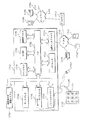
FIG. 11 is a block diagram showing an embodiment of a lens apparatus according to the present invention. The
[0034]
12 is a side sectional view of the lens device shown in FIG. The
[0035]
[0036]
The
[0037]
FIG. 13 shows an example of a substrate, an overlay image, and a substrate overlaid with an overlay image viewed from the lens viewport shown in FIGS. 11 and 12. The
[0038]
From this information, the
[0039]
FIG. 14 shows another example of the substrate, the overlay image, and the substrate on which the overlay image viewed from the lens viewport shown in FIGS. 11 and 12 is overlaid. More specifically, FIG. 14 shows how the system responds when the user moves the
[0040]
From this information, the
[0041]
Each of the systems described with respect to FIGS. 7, 8, 9, and 12 aligns image information with a substrate. To align, it is necessary to decode the embedded data on the substrate to determine the content of the information to be aligned and the orientation of the information relative to the substrate. Accordingly, the decoding and alignment techniques described herein can be applied to any system according to the present invention.
[0042]
In order to align the overlay image with the substrate, it is necessary to accurately determine the orientation of the substrate relative to the image capture device. To determine the angle of orientation relative to the image capture device, the
[0043]
FIG. 15 is a flowchart illustrating processing performed by the
[0044]
The
[0045]
In other embodiments, the glyph does not include a context label. In this embodiment,
[0046]
FIG. 16 graphically illustrates the process of generating an image in the superimposed neighborhood image in the glyph grid image according to the flowchart of FIG. More specifically, in the embodiment shown in FIG. 16,
[0047]
FIG. 17 is a flowchart illustrating the processing performed by
[0048]
If there is sufficient contrast (step 168), the
[0049]
If the limited number of sampling attempts is exceeded, the
[0050]
FIG. 18 is a flowchart illustrating a process executed by the
[0051]
FIG. 19 graphically illustrates one method for finding the center of mass of a glyph according to the present invention. The Y coordinate of the center of mass is
[0052]
[Expression 1]
The X coordinate of the center of mass is
[0053]
[Expression 2]
[0054]
[Equation 3]
[0055]
20 and 21 illustrate a method for analyzing a composite image to accurately determine the rotation angle of the composite image, as shown in FIG. The coderant offset angle of the composite image represents an accurate determination of the orientation of the glyph grid in the original captured image, subject to the determination of the appropriate angle coderant. By combining the cordrant offset angle and the angular cordant, the relative angle between the image capture device and the substrate is completely determined. FIG. 20 shows one example in which the cordrant offset angle is 0 °, and FIG. 21 shows another example in which the cordrant offset angle is a finite angle θ.
[0056]
The apparatus and method according to the present invention was filed on August 31, 1998, which is incorporated herein by reference. US Patent Application No. entitled “Glyph Address Carpet Method and Apparatus for Providing Location Information in Address Space” (Case Number: 07447.0010-00000) Address carpet codes and associated processes similar to those shown in FIG.
[0057]
FIG. 22 shows an embodiment of an address code encoded in a portion of a glyph address carpet similar to the u and v codes described above. Addresses are encoded by alternating rows (rows) of “A” address code sequences and “B” address code sequences. The position along each sequence in each row must be clearly determinable from a predetermined length subsequence. For example, the N-bit shift register maximum length code can be uniquely determined by the position from the N-bit subsequence. Each address code sequence is a 15-bit sequence in which the A sequence is indexed left and right and the B sequence is indexed in the reverse direction, that is, from right to left. Each line of the A code sequence is offset by two glyph positions relative to the previous line and the next line of the A address. Similarly, each row of the B code sequence is offset by two positions in opposite directions. Thus, the encoding method has two sets of key characteristics: two sets of one-dimensional unique address codes and two sets so that each pair of offsets from these two sets is unique. Relative offsets selected from among the members. This establishes a two-dimensional unique address location.
[0058]
The
[0059]
The orientation of the image is determined by analyzing the captured image. This process is called clarification. One method of clarification is described in US Pat. No. 5,521,372 to Hecht et al., Which is expressly incorporated herein by reference. After determining the appropriate orientation of the image, the
[0060]
23 and 24 form a flowchart illustrating an exemplary clarification and address decoding process performed by
[0061]
FIG. 25 shows a binary data matrix (BDM) 2310 formed from a glyph lattice captured by an image capture device. A location in the BDM corresponds to a location in the glyph grid, so that the size of the BDM closely corresponds to the size of the glyph grid.
[0062]
Each location in the glyph grid is analyzed to determine which value should be placed at the corresponding location in the BDM. Initially, the BDM is filled with a value indicating that no attempt has been made to read this glyph, eg, φ. When the glyph corresponding to a specific location is analyzed, φ is replaced by a value indicating the analysis result of the glyph.
[0063]
In FIG. 25, B indicates the border position, X indicates that no interpretable glyph was found at the corresponding position in the glyph grid, E indicates the glyph at the edge of the captured image portion, and 0 indicates the backward slash glyph. 1 indicates a forward slash glyph, and d indicates a label code. The area of the matrix corresponding to the captured image is filled with 0s and 1s, the edges are bounded by E, and X corresponds to a location with no readable glyphs. BDM has an overall pattern similar to FIG. 25, but values are often not evenly distributed, as shown in FIG. If the glyph is erased, for example, glyph location within the captured image area may result in X. Some values were surrounded by circles or squares to show two separate chord sequences that are staggered in opposite directions.
[0064]
The image capture device may be oriented relative to the substrate at any angle.
Thus, the captured image can be oriented at any angle. Thus, even if 0 and 1 BDMs are obtained from the captured image, the BDM is 0 ° (directly oriented), 90 ° with respect to the original code pattern in the glyph address carpet from which the image was captured. Whether it is oriented at °, 180 °, or 270 ° is unclear. Until the orientation of the captured image is determined, it is impossible to derive an accurate address code from the BDM. The orientation can be provided by auxiliary information such as physical system constraints. However, the orientation can be uniquely determined directly from the address code.
[0065]
After converting the glyphs to 0 and 1, a reference glyph location is selected (step 2211). This location can be selected in a wide variety of ways, but is generally a location that represents a selection. For example, the reference glyph location may be the center of the BDM.
[0066]
The image is processed by
[0067]
[0068]
FIG. 26 is a flowchart illustrating an embodiment of
[0069]
The
[0070]
Steps on the right side of FIG. 26 are the same as
[0071]
The processing steps of FIG. 26 are performed on the odd and even rows of BDM1 and the odd and even rows of BDM2. From this information, the correlation value C1 for BDM1 (as determined by FIG. 26 for the row of BDM1) is C1.EVEN+ C1ODDAnd the correlation value C2 for BDM2 (as determined by FIG. 26 for the row of BDM1) is C2EVEN+ C2ODDSet to
[0072]
FIG. 27 shows how to determine in which direction the code of every other line of correlation is shifted. For example, as indicated by A1 circled along the diagonal running to the right, the code along the diagonal starting from A1 in the first position of the second row is along the diagonal, excluding erasures and errors. Must have the same value in every other row. Similarly, the code along the diagonal starting from B1 in the upper right corner has the same value in every other line along the diagonal, except for erasures and errors, as indicated by the boxed B1 There is a need. This means that B2, B3,. . . This is also true for each value along the diagonal of the odd rows running from each of B15. In this way, the strong correlation along the diagonal line running down to the left on odd lines and the strong correlation along the diagonal line running down to the right on even lines shifts the code in the even lines to the right. This indicates that the code in the odd-numbered line is shifted to the left.
[0073]
Thus, for each BDM, there are four correlation values: 1) odd rows from right to left, 2) odd rows from left to right, 3) even rows from right to left, 4) even numbers from left to right Line. From these correlation values, the strongest correlation value for even-numbered rows and the strongest correlation value for odd-numbered rows are selected.EVEN+ CODD(
[0074]
Codes on odd lines are staggered in one direction, and codes on even lines are staggered in the other direction. In connection with knowing the respective codes running on the odd and even lines, the staggered characteristics of the codes determine the appropriate 0 ° orientation of the BDM.
[0075]
Returning to FIG. 23, if C1 is greater than C2 (step 2220), BDM1 is selected for further processing. The fact that C1 is greater than C2 indicates that the one-dimensional code of BDM1 is most strongly correlated and is thereby directed to either 0 ° or 180 ° (step 2222). If C2 is greater than C1, the higher correlation indicates that BDM2 is directed to either 0 ° or 180 °, so BDM2 is selected for further processing (step 2224). In this way, an accurate BDM was found. Prior to determining the address location of the captured image, however, the
[0076]
FIG. 24 is a flowchart illustrating the steps in which the
[0077]
The
[0078]
More specifically, the two adjacent rows of the BDM closest to the reference element selected in
1) Each of P1 and V1 represents a peak correlation value and corresponds to a position for
2) Each of Q1 and U1 represents a peak correlation value and corresponds to a position for
3) Each of P2 and V2 represents a peak correlation value and corresponds to a position for
4) Each of Q2 and U2 represents a peak correlation value and corresponds to a position for
[0079]
i = 1 or 2, corresponding to the size of the peak, UiAnd ViAre used to determine the X and Y values corresponding to the reference element selected in
X = (Vi-Ui+ Length of all cords) / 2
Y = (Vi+ Ui-Length of all cords) / 2
[0080]
Next, the calculated X and Y positions are returned (step 2238). Note that the diagonal lines correspond to constant values of U and V, respectively, while the rows and columns correspond to constant values X and Y. Note also that U and V are used directly as address parameters.
[0081]
Thus, the X and Y values associated with the reference point selected in
[0082]
FIG. 28 illustrates a method for rapid processing when continuous image capture is processed from the image capture device when there is relative motion (motion) between the image capture device and the substrate at a speed of a predetermined value V or less. . Initially, the first image is captured and the location no. The entire address space is searched according to the above teachings to determine one location coordinate. In the example shown in FIG. 1 is the coordinate value u16, Vtwenty twoHave If the motion speed is less than V and the time T is between captures, the next capture is the location number. It is constrained within a circle of radius R = VT around one coordinate. Therefore, the location No. The range of the index used by searching for the correlation maximum value indicating 2 is the location number. Index range u of locations within a circle of radius R around the coordinates of 1i, VjIt can be limited to. If no suitable correlation peak is found, processing returns to searching the entire address space. The lack of a suitable correlation peak indicates that the motion has jumped out of the circle or the substrate has changed.
[0083]
This method can speed up the information extraction process and enable applications such as real-time frame-to-frame image capture. This can be used for smoothed motion display and gesture motion capture.
[0084]
FIG. 29 is a block diagram of a user interface image capture system that can be used to capture a user selected portion of a graphical user interface, such as the
[0085]
[0086]
The registered
[0087]
The camera pen 1710 and
[0088]
A camera pen 1710 is connected to the
[0089]
The user selects by placing the camera pen 1710 on or near the visual index on the
[0090]
[0091]
In one embodiment,
[0092]
[0093]
The system shown in FIG. 29 may be used to implement the glyph address carpet capture and conversion system described herein. The apparatus and methods described herein may be implemented by
[0094]
Such programs are read into
[0095]
As used herein, the term “computer-readable medium” refers to any medium that participates in providing instructions to
[0096]
Common forms of computer readable media are, for example, floppy disk, flexible disk, hard disk, magnetic tape, or any other magnetic storage medium, CD-ROM, any other optical medium, punch card, paper tape, hole Any other physical medium, RAM, PROM, EPROM, FLASH-EPROM, any other memory chip or cartridge, carrier wave as described below, or any other that the computer can read and use Media.
[0097]
Various forms of computer readable media may be involved in carrying out one or more sequences of instructions for execution to
[0098]
[0099]
The link between the
[0100]
Through a network via a link between the
[0101]
Program code received over a network may be executed by
[0102]
FIG. 30 shows another embodiment of the image registration system according to the present invention. The
[0103]
Since the
[0104]
Based on the decoded information, image information is generated and displayed on the
[0105]
The
[0106]
FIG. 31 is a block diagram showing a cutaway side view of the
[0107]
The
[0108]
In view of the specification and practice of the disclosed embodiments, other embodiments of the invention will be apparent to those skilled in the art. The specification and examples are for illustrative purposes only, and the true scope and spirit of the invention is defined by the following claims and their equivalents.
[Brief description of the drawings]
FIG. 1 is a schematic diagram illustrating glyph marks and characteristics of codes embodied in the glyph marks.
FIG. 2 is a diagram showing an embodiment of an image combining graphics and glyphs according to the present invention.
FIG. 3 is an enlarged view showing a part of the image shown in FIG. 2;
FIG. 4 shows a drawing image having a glyph tone according to the present invention.
FIG. 5 illustrates an example of a portion of a glyph address carpet code having an overlay tiled label code.
FIG. 6 is a diagram illustrating a system for reading an image having embedded data, decoding embedded data in the image, and developing information that can be perceived by humans based on the decoded embedded data.
FIG. 7 is a diagram showing a logical configuration of elements according to the present invention.
FIG. 8 shows another embodiment of the system according to the invention.
FIG. 9 illustrates another embodiment of a system incorporated by the present invention.
FIG. 10 is a diagram illustrating information alignment according to the present invention.
FIG. 11 is a block diagram showing an embodiment of a lens apparatus according to the present invention.
12 is a cut-away side view of the lens device shown in FIG. 11. FIG.
13 is a diagram illustrating an example of a substrate, an overlay image, and a substrate on which the overlay image is overlaid, as viewed from the lens viewport illustrated in FIGS. 11 and 12. FIG.
14 is a diagram showing another embodiment of the substrate, the overlay image, and the substrate on which the overlay image is overlaid, as viewed from the lens viewport shown in FIGS. 11 and 12. FIG.
FIG. 15 is a flowchart illustrating processing performed by a
FIG. 16 is a diagram graphically showing processing for generating one of the adjacent images superimposed in the glyph grid image in accordance with the flowchart of FIG. 17;
FIG. 17 is a flowchart illustrating processing performed by a computer to determine a coderant offset angle using a grid image.
FIG. 18 is a flowchart illustrating a process performed by a computer to generate a composite grid image that is used in determining a coderant offset angle using a composite grid image.
FIG. 19 shows the location of the glyph mass center.
FIG. 20 is a diagram showing a state where a composite image is analyzed in order to accurately determine the rotation angle of the composite image, as shown in FIG.
FIG. 21 is a diagram showing a state where a composite image is analyzed in order to accurately determine the rotation angle of the composite image, as shown in FIG. 16;
FIG. 22 illustrates an embodiment of an address code encoded in a portion of a glyph address carpet.
FIG. 23 is a diagram forming a flow chart illustrating clarification and address decoding processing performed by a computer.
FIG. 24 is a diagram forming a flow chart illustrating clarification and address decoding processing performed by a computer.
FIG. 25 shows a binary data matrix formed from a glyph lattice.
26 is a flowchart showing an embodiment of the correlation step of FIG. 24. FIG.
FIG. 27 is a diagram showing how correlation determines the direction in which codes are shifted in every other row;
FIG. 28 illustrates a method for priority processing when continuous capture is processed from an image capture device.
FIG. 29 is a block diagram illustrating a user interface image capture system that may be used to capture a user selected portion of a graphical user interface.
FIG. 30 is a block diagram showing another embodiment of an image registration system according to the present invention.
FIG. 31 is a block diagram showing a cut side surface of a camera mouse.
[Explanation of symbols]
21 glyph mark
22 Glyph
23 Enlarged area
24 Substrate
25 glyph code pattern
Claims (2)
前記合成画像を読み取って画像データを得る読取手段(80)と、
前記読取手段により読み取って得られた前記画像データ中の前記複数の傾斜線分に基づいて前記符号化データを復号化して前記補足情報及び前記配置情報を得る復号化手段(88)と、
前記復号化手段による前記復号化によって得られた前記補足情報及び前記配置情報に基づいて、該補足情報に基づく補足情報画像を、前記半透明ミラーの前記第1の面の前記配置位置に対応する位置に形成する画像形成手段(84)と、
画像形成システム。Encoded data obtained by encoding 0 and 1 with supplementary information for supplementing the original image and arrangement position information indicating the arrangement position on the original image on which the supplementary information image based on the supplementary information is arranged, and a reference in the original image Inclined with respect to the base on the base on which a composite image is formed by combining the plurality of inclined lines with the original image. And a translucent mirror (82) provided with a first surface and a surface facing the first surface, and disposed at a position where the user can visually recognize the composite image from the first surface side. )When,
Reading means (80) for reading the composite image and obtaining image data;
Decoding means (88) for decoding the encoded data based on the plurality of inclined line segments in the image data obtained by reading by the reading means to obtain the supplementary information and the arrangement information;
Based on the supplementary information and the arrangement information obtained by the decoding by the decoding unit, a supplementary information image based on the supplementary information corresponds to the arrangement position of the first surface of the translucent mirror. Image forming means (84) to be formed at the position;
Image forming system.
前記合成画像を読み取って画像データを得る読取手段(90)と、
前記読取手段により読み取って得られた前記画像データ中の前記複数の傾斜線分に基づいて前記符号化データを復号化して前記補足情報及び前記配置情報を得る復号化手段(92)と、
前記復号化手段による前記復号化によって得られた前記補足情報及び前記配置情報に基づいて、該補足情報に基づく補足情報画像を、前記投影面の前記配置位置に対応する位置に形成する画像形成手段(94)と、
画像形成システム。Encoded data obtained by encoding 0 and 1 with supplementary information for supplementing the original image and arrangement position information indicating the arrangement position on the original image on which the supplementary information image based on the supplementary information is arranged, and a reference in the original image Inclined with respect to the base on the base on which a composite image is formed by combining the plurality of inclined lines with the original image. And a mirror (96) that reflects and projects the light representing the composite image on the substrate onto the projection plane;
Reading means (90) for reading the composite image and obtaining image data;
Decoding means (92) for decoding the encoded data based on the plurality of inclined line segments in the image data obtained by reading by the reading means to obtain the supplementary information and the arrangement information;
Image forming means for forming a supplementary information image based on the supplementary information at a position corresponding to the arrangement position on the projection plane based on the supplementary information and the arrangement information obtained by the decoding by the decoding means. (94)
Image forming system.
Applications Claiming Priority (6)
| Application Number | Priority Date | Filing Date | Title |
|---|---|---|---|
| US09/456,105 US6935562B2 (en) | 1999-12-06 | 1999-12-06 | Operations on images having glyph carpets |
| US456105 | 1999-12-06 | ||
| US09/454,526 US6880755B2 (en) | 1999-12-06 | 1999-12-06 | Method and apparatus for display of spatially registered information using embedded data |
| US09/455,304 US6678425B1 (en) | 1999-12-06 | 1999-12-06 | Method and apparatus for decoding angular orientation of lattice codes |
| US455304 | 1999-12-06 | ||
| US454526 | 1999-12-06 |
Publications (3)
| Publication Number | Publication Date |
|---|---|
| JP2001312733A JP2001312733A (en) | 2001-11-09 |
| JP2001312733A5 JP2001312733A5 (en) | 2008-01-24 |
| JP4651184B2 true JP4651184B2 (en) | 2011-03-16 |
Family
ID=27412606
Family Applications (1)
| Application Number | Title | Priority Date | Filing Date |
|---|---|---|---|
| JP2000371332A Expired - Fee Related JP4651184B2 (en) | 1999-12-06 | 2000-12-06 | Method and apparatus for registering, displaying and decoding spatially aligned information |
Country Status (3)
| Country | Link |
|---|---|
| EP (2) | EP1557793B1 (en) |
| JP (1) | JP4651184B2 (en) |
| DE (2) | DE60039314D1 (en) |
Families Citing this family (2)
| Publication number | Priority date | Publication date | Assignee | Title |
|---|---|---|---|---|
| JP5924035B2 (en) * | 2012-03-08 | 2016-05-25 | 富士ゼロックス株式会社 | Information processing apparatus and information processing program |
| GB2501921B (en) * | 2012-05-11 | 2017-05-03 | Sony Computer Entertainment Europe Ltd | Augmented reality system |
Family Cites Families (9)
| Publication number | Priority date | Publication date | Assignee | Title |
|---|---|---|---|---|
| EP0254644A3 (en) * | 1986-07-22 | 1990-07-18 | Schlumberger Technologies, Inc. | Mask alignment and measurement of critical dimensions in integrated circuits |
| CA2044404C (en) * | 1990-07-31 | 1998-06-23 | Dan S. Bloomberg | Self-clocking glyph shape codes |
| US5477012A (en) * | 1992-04-03 | 1995-12-19 | Sekendur; Oral F. | Optical position determination |
| US6090555A (en) * | 1997-12-11 | 2000-07-18 | Affymetrix, Inc. | Scanned image alignment systems and methods |
| JP3639328B2 (en) * | 1994-10-14 | 2005-04-20 | オリンパス株式会社 | Information recording medium, two-dimensional code, information reproducing system, and information reproducing method |
| US5988505A (en) * | 1996-06-03 | 1999-11-23 | Symbol Technologies, Inc. | Omnidirectional reading of two-dimensional symbols |
| JP3275766B2 (en) * | 1996-08-30 | 2002-04-22 | 富士ゼロックス株式会社 | Concealed image processing system |
| US5937110A (en) * | 1996-12-20 | 1999-08-10 | Xerox Corporation | Parallel propagating embedded binary sequences for characterizing objects in N-dimensional address space |
| JP3438516B2 (en) * | 1997-02-13 | 2003-08-18 | 富士ゼロックス株式会社 | Form document and form document processing method and apparatus |
-
2000
- 2000-12-04 EP EP05009155A patent/EP1557793B1/en not_active Expired - Lifetime
- 2000-12-04 EP EP00310774A patent/EP1107184B1/en not_active Expired - Lifetime
- 2000-12-04 DE DE60039314T patent/DE60039314D1/en not_active Expired - Lifetime
- 2000-12-04 DE DE60022969T patent/DE60022969T2/en not_active Expired - Lifetime
- 2000-12-06 JP JP2000371332A patent/JP4651184B2/en not_active Expired - Fee Related
Also Published As
| Publication number | Publication date |
|---|---|
| DE60022969T2 (en) | 2006-05-04 |
| EP1107184A2 (en) | 2001-06-13 |
| EP1557793B1 (en) | 2008-06-25 |
| JP2001312733A (en) | 2001-11-09 |
| EP1107184A3 (en) | 2003-09-17 |
| EP1107184B1 (en) | 2005-10-05 |
| DE60039314D1 (en) | 2008-08-07 |
| EP1557793A3 (en) | 2006-06-14 |
| DE60022969D1 (en) | 2005-11-10 |
| EP1557793A2 (en) | 2005-07-27 |
Similar Documents
| Publication | Publication Date | Title |
|---|---|---|
| US6678425B1 (en) | Method and apparatus for decoding angular orientation of lattice codes | |
| US6935562B2 (en) | Operations on images having glyph carpets | |
| US6880755B2 (en) | Method and apparatus for display of spatially registered information using embedded data | |
| EP0984390B1 (en) | Apparatus for providing location information in a multidimensional address space | |
| EP1016953A2 (en) | Multi-level selection methods and apparatus using context identification | |
| US7317557B2 (en) | Paper-to-computer interfaces | |
| US7950589B2 (en) | Program, information storage medium, two-dimensional code generation system, image generation system and printed material | |
| JP4833555B2 (en) | Enhanced method of m-sequence decoding and error correction | |
| EP1553485B1 (en) | Positionally encoded document image analysis and labeling | |
| CN100442214C (en) | Decoding and error correction in 2-d arrays | |
| RU2375740C2 (en) | DETERMINATION OF LOCATION OF LINES BY m-ARRAY DECODING AND FAST COMPARISON OF IMAGES | |
| US7817816B2 (en) | Embedded interaction code enabled surface type identification | |
| RU2369901C2 (en) | On-site location using fast image matching | |
| US20030082505A1 (en) | Assisted reading method and apparatus | |
| JP7150980B2 (en) | Information device interaction method and system based on optical label | |
| EP1553486A1 (en) | Global localization by fast image matching | |
| JP4651184B2 (en) | Method and apparatus for registering, displaying and decoding spatially aligned information | |
| EP1107171A2 (en) | Method and apparatus for implementing a camera mouse | |
| Miyaoku et al. | C-Band: A Flexible Color Ring Tag System |
Legal Events
| Date | Code | Title | Description |
|---|---|---|---|
| A521 | Request for written amendment filed |
Free format text: JAPANESE INTERMEDIATE CODE: A523 Effective date: 20071205 |
|
| A621 | Written request for application examination |
Free format text: JAPANESE INTERMEDIATE CODE: A621 Effective date: 20071205 |
|
| A977 | Report on retrieval |
Free format text: JAPANESE INTERMEDIATE CODE: A971007 Effective date: 20100624 |
|
| A131 | Notification of reasons for refusal |
Free format text: JAPANESE INTERMEDIATE CODE: A131 Effective date: 20100629 |
|
| A521 | Request for written amendment filed |
Free format text: JAPANESE INTERMEDIATE CODE: A523 Effective date: 20100913 |
|
| TRDD | Decision of grant or rejection written | ||
| A01 | Written decision to grant a patent or to grant a registration (utility model) |
Free format text: JAPANESE INTERMEDIATE CODE: A01 Effective date: 20101116 |
|
| A01 | Written decision to grant a patent or to grant a registration (utility model) |
Free format text: JAPANESE INTERMEDIATE CODE: A01 |
|
| A61 | First payment of annual fees (during grant procedure) |
Free format text: JAPANESE INTERMEDIATE CODE: A61 Effective date: 20101214 |
|
| R150 | Certificate of patent or registration of utility model |
Free format text: JAPANESE INTERMEDIATE CODE: R150 |
|
| FPAY | Renewal fee payment (event date is renewal date of database) |
Free format text: PAYMENT UNTIL: 20131224 Year of fee payment: 3 |
|
| R250 | Receipt of annual fees |
Free format text: JAPANESE INTERMEDIATE CODE: R250 |
|
| R250 | Receipt of annual fees |
Free format text: JAPANESE INTERMEDIATE CODE: R250 |
|
| LAPS | Cancellation because of no payment of annual fees |