JP4649093B2 - Optical reader imaging module - Google Patents

Optical reader imaging module Download PDF

Info

Publication number
JP4649093B2
JP4649093B2 JP2002571699A JP2002571699A JP4649093B2 JP 4649093 B2 JP4649093 B2 JP 4649093B2 JP 2002571699 A JP2002571699 A JP 2002571699A JP 2002571699 A JP2002571699 A JP 2002571699A JP 4649093 B2 JP4649093 B2 JP 4649093B2
Authority
JP
Japan
Prior art keywords
module
aiming
light
led
optical
Prior art date
Legal status (The legal status is an assumption and is not a legal conclusion. Google has not performed a legal analysis and makes no representation as to the accuracy of the status listed.)
Expired - Fee Related
Application number
JP2002571699A
Other languages
Japanese (ja)
Other versions
JP2005507571A (en
JP2005507571A5 (en
Inventor
ジェイ ヘニック ロバート
ピー バーバー チャールズ
コールマン エリック
アーハート マイケル
ピー ギャノン カリーン
シー ガーディナー ロバート
エイチ ハヴェンズ ウィリアム
エル ハンター ヴィヴィアン
ディー マッコール メルヴィン
ルールマン トマス
Original Assignee
ハンド ヘルド プロダクツ インコーポレーティッド
Priority date (The priority date is an assumption and is not a legal conclusion. Google has not performed a legal analysis and makes no representation as to the accuracy of the date listed.)
Filing date
Publication date
Priority claimed from US09/802,579 external-priority patent/US6601768B2/en
Priority claimed from US10/093,136 external-priority patent/US6832725B2/en
Priority claimed from US10/092,789 external-priority patent/US20030029917A1/en
Application filed by ハンド ヘルド プロダクツ インコーポレーティッド filed Critical ハンド ヘルド プロダクツ インコーポレーティッド
Publication of JP2005507571A publication Critical patent/JP2005507571A/en
Publication of JP2005507571A5 publication Critical patent/JP2005507571A5/ja
Application granted granted Critical
Publication of JP4649093B2 publication Critical patent/JP4649093B2/en
Anticipated expiration legal-status Critical
Expired - Fee Related legal-status Critical Current

Links

Images

Classifications

    • GPHYSICS
    • G06COMPUTING; CALCULATING OR COUNTING
    • G06KGRAPHICAL DATA READING; PRESENTATION OF DATA; RECORD CARRIERS; HANDLING RECORD CARRIERS
    • G06K7/00Methods or arrangements for sensing record carriers, e.g. for reading patterns
    • G06K7/10Methods or arrangements for sensing record carriers, e.g. for reading patterns by electromagnetic radiation, e.g. optical sensing; by corpuscular radiation
    • G06K7/10544Methods or arrangements for sensing record carriers, e.g. for reading patterns by electromagnetic radiation, e.g. optical sensing; by corpuscular radiation by scanning of the records by radiation in the optical part of the electromagnetic spectrum
    • G06K7/10821Methods or arrangements for sensing record carriers, e.g. for reading patterns by electromagnetic radiation, e.g. optical sensing; by corpuscular radiation by scanning of the records by radiation in the optical part of the electromagnetic spectrum further details of bar or optical code scanning devices
    • G06K7/10881Methods or arrangements for sensing record carriers, e.g. for reading patterns by electromagnetic radiation, e.g. optical sensing; by corpuscular radiation by scanning of the records by radiation in the optical part of the electromagnetic spectrum further details of bar or optical code scanning devices constructional details of hand-held scanners
    • GPHYSICS
    • G06COMPUTING; CALCULATING OR COUNTING
    • G06KGRAPHICAL DATA READING; PRESENTATION OF DATA; RECORD CARRIERS; HANDLING RECORD CARRIERS
    • G06K7/00Methods or arrangements for sensing record carriers, e.g. for reading patterns
    • G06K7/10Methods or arrangements for sensing record carriers, e.g. for reading patterns by electromagnetic radiation, e.g. optical sensing; by corpuscular radiation
    • G06K7/10544Methods or arrangements for sensing record carriers, e.g. for reading patterns by electromagnetic radiation, e.g. optical sensing; by corpuscular radiation by scanning of the records by radiation in the optical part of the electromagnetic spectrum
    • G06K7/10712Fixed beam scanning
    • G06K7/10722Photodetector array or CCD scanning
    • G06K7/10742Photodetector array or CCD scanning including a diffuser for diffusing the light from the light source to create substantially uniform illumination of the target record carrier
    • HELECTRICITY
    • H05ELECTRIC TECHNIQUES NOT OTHERWISE PROVIDED FOR
    • H05KPRINTED CIRCUITS; CASINGS OR CONSTRUCTIONAL DETAILS OF ELECTRIC APPARATUS; MANUFACTURE OF ASSEMBLAGES OF ELECTRICAL COMPONENTS
    • H05K1/00Printed circuits
    • H05K1/02Details
    • H05K1/14Structural association of two or more printed circuits
    • H05K1/144Stacked arrangements of planar printed circuit boards

Landscapes

  • Physics & Mathematics (AREA)
  • Engineering & Computer Science (AREA)
  • Electromagnetism (AREA)
  • Artificial Intelligence (AREA)
  • Toxicology (AREA)
  • General Health & Medical Sciences (AREA)
  • Health & Medical Sciences (AREA)
  • Computer Vision & Pattern Recognition (AREA)
  • General Physics & Mathematics (AREA)
  • Theoretical Computer Science (AREA)
  • Facsimile Heads (AREA)
  • Studio Devices (AREA)
  • Facsimile Scanning Arrangements (AREA)
  • Camera Bodies And Camera Details Or Accessories (AREA)

Description

関連出願の相互参照
このPCT出願は、以下の8つの非仮出願および仮出願:(1)“屈折型拡散器を備えた光学読取装置用の撮像モジュール”というタイトルで2001年3月8日に出願された米国非仮出願第09/802,579号、(2)“データ収集小型撮像モジュールおよび照準装置”というタイトルで2001年6月26日に出願された米国仮出願第60/301,036号、(3)“多色光学読取装置の照射”というタイトルで2001年10月5日に出願された米国仮出願第60/327,249号、(4)“データ収集小型撮像モジュールおよび照準装置”というタイトルで2001年9月11日に出願された米国仮出願第60/322,776号、(5)“導電性支柱を備えた光学読取装置”というタイトルで2001年10月12日に出願された米国仮出願第60/328,855号、(6)“位置合せ素子を備えた光学読取装置モジュール”というタイトルで2001年11月9日に出願された米国仮出願第60/345,523号、(7)“光学読取装置撮像モジュール”というタイトルで2002年3月7日に出願された米国非仮出願第(出願番号未定、事件番号283-309.11)号、(8)“多色照射を備えた光学読取装置”というタイトルで2002年3月7日に出願された米国非仮出願第(出願番号未定、事件番号283-309.12)号に対する優先権を主張する。
Cross-reference of related applications This PCT application was filed on March 8, 2001 under the title of the following eight non-provisional applications and provisional applications: U.S. Provisional Application No. 09 / 802,579, (2) U.S. Provisional Application No. 60 / 301,036, filed June 26, 2001, entitled "Data Collection Miniature Imaging Module and Sighting Device", (3 ) US Provisional Application No. 60 / 327,249 filed October 5, 2001 under the title "Irradiation of Multicolor Optical Reader", (4) 2001 under the title "Data Collection Miniature Imaging Module and Sighting Device" US Provisional Application No. 60 / 322,776 filed on September 11, (5) US Provisional Application No. 60 / filed on October 12, 2001 under the title "Optical Reader with Conductive Posts" 328,855, (6 US Provisional Application No. 60 / 345,523 filed on November 9, 2001 under the title “Optical Reader Module with Alignment Elements”, (7) Title “Optical Reader Imaging Module”, March 2002 US non-provisional application filed on May 7 (application number undecided, case number 283-309.11), (8) filed March 7, 2002 under the title "Optical Reader with Multicolor Irradiation" Claims priority to US non-provisional application filed (application number pending, case number 283-309.12).

本発明は、一般的には光学読取装置に関し、さらに詳細には光学読取装置用の撮像モジュールに関する。   The present invention generally relates to an optical reader, and more particularly to an imaging module for an optical reader.

大部分の画像信号生成データ収集装置は、対象領域を照射するための内蔵照射素子が必要である。内蔵照射素子およびこれらの素子を支持する構造部材は、かなりのスペースを消費する。レーザスキャナベースの撮像モジュールは、ますます小さなサイズで入手可能となってきている。シンボルSE900撮像モジュールは、小型のレーザベース画像撮像モジュールの一例である。SE900の外観プロファイルは、約0.81インチ幅(“x”)×0.45インチ高(“y”)である。   Most image signal generation data collection devices require a built-in irradiation element for irradiating the target area. The built-in illumination elements and the structural members that support these elements consume considerable space. Laser scanner-based imaging modules are becoming available in increasingly smaller sizes. The symbol SE900 imaging module is an example of a small laser-based imaging module. The appearance profile of SE900 is approximately 0.81 inch wide (“x”) × 0.45 inch high (“y”).

しかしながら、レーザベースの撮像モジュールでは幾つかの問題点が指摘されてきた。第1に、レーザベースの撮像モジュールは、2次元画像を取込むのに好適ではなく、従って2次元マトリックスバーコードやOCR文字などのような、あるタイプの2次元証印を復号するシステムでは使用することができない。既存のレーザベースの撮像モジュールはPDF417などのスタック型2次元シンボルを読取るが、一般には2次元画像の取り込みには適していない。レーザスキャナベースの画像エンジンを2次元画像取込みに適合させようという試みは、不調に終わっている。レーザスキャン2次元画像エンジンは、低解像度の画像信号を生成するが、費用がかかりスペースを消費するものであると考えられてきた。レーザベースのバーコードに関して指摘される別の大きな問題は、耐久性の欠如である。レーザスキャンエンジンモジュールは、精緻に搭載される可動ミラーを要する。ミラー搭載構造は、モジュールを内蔵しているハウジングの突然の衝撃によって簡単にずれたり壊れたりする。レーザスキャナベースの撮像モジュールの機械的な複雑さは、該モジュールが2次元画像信号を生成しなければならない場合に著しく増加する。   However, several problems have been pointed out with laser-based imaging modules. First, laser-based imaging modules are not suitable for capturing two-dimensional images and are therefore used in systems that decode certain types of two-dimensional indicia, such as two-dimensional matrix barcodes and OCR characters. I can't. Existing laser-based imaging modules read stacked two-dimensional symbols such as PDF417, but are generally not suitable for capturing two-dimensional images. Attempts to adapt a laser scanner-based image engine for 2D image capture have been unsuccessful. Laser-scanned two-dimensional image engines produce low resolution image signals, but have been considered expensive and space consuming. Another major problem pointed out with laser-based barcodes is lack of durability. The laser scan engine module requires a precisely mounted movable mirror. The mirror mounting structure is easily displaced or broken by sudden impact of the housing containing the module. The mechanical complexity of a laser scanner-based imaging module is significantly increased when the module has to generate a two-dimensional image signal.

2次元証印を読取ることができず、かつ壊れやすいというレーザスキャナ撮像モジュールに関する重大な問題にも関わらず、データ形式読取機器のユーザの中には、これらのモジュールの示す幾つかの利点に関心を持ち続けている者もいる。まず、上述したように、レーザスキャベースの撮像モジュールは、その限られた機能性のために、サイズおよび重量の小さいパッケージに簡単に作ることができる。第2に、ユーザの中には、レーザスキャナベースの撮像モジュールによって対象上に投影されるすっきりと鮮やかな照準および照射パターンに肯定的に反応する者がいる。レーザスキャナベースの撮像モジュールは、対象の上に平行化された狭い光線を投影する。この光線は、照準線を定義するために走査される。前記の線が良好に定義されているので、ユーザは対象領域内における読取すべき証印上にスキャンラインを簡単に配置することができる。撮像モジュール照準パターンの位置決めは、対象証印に“照準を定める”と言われることもある。   Despite the serious problems with laser scanner imaging modules that cannot read 2D indicia and are fragile, some users of data format readers are interested in some of the advantages of these modules. Some people have it. First, as described above, a laser-scan based imaging module can be easily made in a small size and weight package due to its limited functionality. Secondly, some users react positively to the clean and bright aiming and illumination patterns projected onto the object by the laser scanner-based imaging module. Laser scanner-based imaging modules project a collimated narrow beam onto the object. This ray is scanned to define a line of sight. Since the line is well defined, the user can easily place the scan line on the indicia to be read in the target area. The positioning of the imaging module aiming pattern is sometimes referred to as “defining aim” on the target indicia.

本発明は、その主要な側面に従って大まかに述べると、プリント回路基板と、前記プリント回路基板に電気的に接続された画像センサと、少なくとも1つの光学素子を支持するための支持アセンブリと、対象上に照射パターンを生成するための照射システムと、を備える撮像モジュールである。前記照射システムは、照射光源と、該照射光源からの光を拡散するための拡散器とを備えることができる。このモジュールは、照準光源と、前記照準光源からの光を絞るための開口と、照準パターンを対象領域に投影するための光学素子とを有する照準システムをさらに備えることができる。モジュールのサイズを小さくするために、照射システムと照準システムの一方または両方が、ミラーまたはプリズムなどの光変向素子を備えることができる。   The present invention, broadly described in accordance with its principal aspects, is a printed circuit board, an image sensor electrically connected to the printed circuit board, a support assembly for supporting at least one optical element, And an irradiation system for generating an irradiation pattern. The irradiation system may include an irradiation light source and a diffuser for diffusing light from the irradiation light source. The module may further include an aiming system having an aiming light source, an aperture for converging light from the aiming light source, and an optical element for projecting an aiming pattern onto a target region. To reduce the size of the module, one or both of the illumination system and the aiming system can be provided with a light turning element such as a mirror or a prism.

別の側面によれば、撮像モジュールは、撮像モジュールの様々な構成要素を支持するための支柱を備えることができる。このモジュールは、画像センサを担持する第1の回路基板と、少なくとも1つの光源を担持する第2の回路基板と、第1の回路基板と第2の回路基板の間に挿置される支持アセンブリと、幾つかの支柱を収容するための、前記第1の回路基板、第2の回路基板、及び支持アセンブリのそれぞれにおいて位置合せされた柱穴とを備え、これらの支柱は、柱穴に収容されると2つの回路基板の間に挿置された支持アセンブリを含む構造を支持するものである。前記支柱は、第1の回路基板と第2の回路基板の間に付加的な電気的コネクタを提供する必要がなくなるように、導電性とすることができる。   According to another aspect, the imaging module can include struts for supporting various components of the imaging module. The module includes a first circuit board carrying an image sensor, a second circuit board carrying at least one light source, and a support assembly inserted between the first circuit board and the second circuit board. And column holes aligned in each of the first circuit board, the second circuit board, and the support assembly for receiving a number of columns, the columns being received in the column holes If so, it supports a structure that includes a support assembly inserted between two circuit boards. The struts can be conductive so that there is no need to provide additional electrical connectors between the first circuit board and the second circuit board.

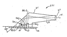
別の側面において、撮像モジュールは、光源と、開口と、前記開口よりも光学的に前方に位置する光学素子とを備えた照準システムを組み込むことができ、該照準システムは広範囲の距離にわたって対象上に切れのよい鮮明な照準パターンを投影する。ある実施例では、レンズ開口効果により、照準パターンが光学的にフォーカスされるとはいえない距離を含む、様々な範囲の距離にわたって切れのよい鮮明な照準パターンを得るように照準システムが構成される。別の実施例では、照準システムは、切れのよい鮮明な照準パターンが幅広い範囲の距離にわたって定められるような態様で、狭い開口から出る光が結像されるように構成される。ある実施例における照準パターンは、対象証印に照準を定めるのに有効な、鮮明に定義された横方向の縁を有している。   In another aspect, the imaging module can incorporate an aiming system that includes a light source, an aperture, and an optical element positioned optically in front of the aperture, the aiming system over a wide range of distances. Project a clear aiming pattern that is sharp. In some embodiments, the lens opening effect configures the aiming system to obtain a sharp and sharp aiming pattern over a range of distances, including distances where the aiming pattern may not be optically focused. . In another embodiment, the aiming system is configured to image light exiting the narrow aperture in such a way that a sharp and sharp aiming pattern is defined over a wide range of distances. The aiming pattern in one embodiment has sharply defined lateral edges that are effective to aim at the target indicia.

さらに別の側面において、本発明のモジュールは、光源から放射される全体の色を制御・変更できるようにそれぞれ単独で駆動可能な複数の異なる色のLEDダイからなる少なくとも1つの多色発光源を備えることができる。多色発光源は、光源から放射される色が、モジュールの現在の適応環境における撮像および読取に合わせて最適化されるように制御することができる。さらにこのモジュールは、多色発光源の制御が、モジュールの視野の色、モジュールから対象までの距離、及び/又は所定の基準が満たされていてフィードバックがユーザに供給されるているなど、検知された状態に応じて自動的に変化するよう構成することができる。モジュールは、さらなる側面において、異なる波長の発光帯域の光を投影する照射光源および照準光源を備えることができる。   In yet another aspect, the module of the present invention comprises at least one multicolor light source consisting of a plurality of differently colored LED dies, each of which can be independently driven to control and change the overall color emitted from the light source. Can be provided. The multicolor light source can be controlled such that the color emitted from the light source is optimized for imaging and reading in the module's current adaptive environment. In addition, the module detects the control of the multicolor light source, such as the color of the module's field of view, the distance from the module to the object, and / or if the predetermined criteria are met and feedback is provided to the user. It can be configured to automatically change according to the state. In a further aspect, the module may comprise an illumination light source and an aiming light source that project light of different wavelength emission bands.

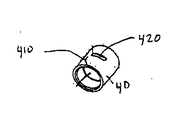
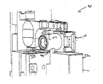
本発明の構成によって可能となる実質的なサイズの縮小に伴って、レンズアセンブリと画像センサとの位置決めが、モジュールの性能に対して大いに影響を与える可能性がでてくる。従って、本発明による撮像モジュールは、レンズアセンブリの位置を画像センサの位置に対して細密調整できるようになされることができる。本発明による保持器・レンズアセンブリは、レンズアセンブリが保持器内において摺動自在に受け入れられるように相補形に構成されている。保持器は、その側壁に2つの開口が画定されている。第1の開口は、保持器内のレンズアセンブリの位置を細密調整する際に用いられる固定ピンを収容する。第2の開口は、レンズアセンブリを保持器に対して接着剤で接合するための接着性物質を受け入れる。接着性物質はさらに、第1の開口に添加してもよい。   With the substantial reduction in size that is possible with the configuration of the present invention, the positioning of the lens assembly and the image sensor can greatly affect the performance of the module. Accordingly, the imaging module according to the present invention can be adjusted so that the position of the lens assembly can be finely adjusted with respect to the position of the image sensor. The cage and lens assembly according to the present invention is configured in a complementary manner so that the lens assembly is slidably received within the cage. The retainer has two openings defined in its side walls. The first opening accommodates a fixing pin used when finely adjusting the position of the lens assembly in the cage. The second opening receives an adhesive material for bonding the lens assembly to the retainer with an adhesive. An adhesive substance may further be added to the first opening.

本発明のさらなる側面において、本発明によるモジュールは、改良された構成を有する照準および照射光源を備えることができる。モジュールに組み込まれた光源は、光源の一部がプリント回路基板によって定義される表面実装LEDを備えることができる。モジュールにおいて表面実装LEDを使用することにより、少なくとも1つの面においてモジュールの寸法を実質的に低減するよう適切に構成する。モジュールは、付加的な位置合せ部材または位置合せ支援アセンブリステップなしで、プリント回路基板に対してしっかりとベンチングされてLEDの厳密な位置合せを実現する、側面リード型表面実装LEDを組込むこともできる。   In a further aspect of the invention, the module according to the invention may comprise a sighting and illumination source having an improved configuration. The light source incorporated in the module can comprise a surface mount LED, a portion of the light source being defined by a printed circuit board. By using surface mount LEDs in the module, it is suitably configured to substantially reduce the dimensions of the module in at least one plane. The module can also incorporate side-leaded surface mount LEDs that are tightly benched against the printed circuit board to provide precise LED alignment without additional alignment members or alignment assist assembly steps. .

本発明のさらに別の側面において、本発明によるモジュールは、モジュールの温度を下げるための1つ以上の放熱構造を備えることができる。別の側面では、モジュールの支柱は、モジュールの部材を構造的に支持し電気的に接続すること以外の目的で使用される。支柱は、取り付けられるとモジュールの一部とみなされる付加的な構造部材(例えばPCB、光学板、放熱構造)を取付けるために利用することができる。支柱は、ハウジング内部部材に、またはモジュールを取り付け可能な別の部材上にモジュールを搭載、支持、または安定化する際に使用することもできる。モジュールは、少なくとも1つの従来の構成要素を無くすよう製造されてモジュールのさらなるサイズ低減を実現させる“非パッケージ”画像センサをさらに具備することができる。モジュールのさらに別の側面では、フレキシブル回路基板を備えることができ、これによってモジュールの形状を変更して、モジュールを様々なキャビティ形状に適合可能とすることができる。モジュールはまた、光源からの光を対象領域に向けるための光管も備えることができる。   In yet another aspect of the present invention, the module according to the present invention may comprise one or more heat dissipation structures for reducing the temperature of the module. In another aspect, the module posts are used for purposes other than structurally supporting and electrically connecting the members of the module. The struts can be used to attach additional structural members (eg, PCBs, optical plates, heat dissipation structures) that are considered part of the module when attached. The struts can also be used to mount, support, or stabilize the module on the housing inner member or on another member to which the module can be attached. The module may further comprise a “non-packaged” image sensor that is manufactured to eliminate at least one conventional component to achieve further size reduction of the module. In yet another aspect of the module, a flexible circuit board can be provided, whereby the shape of the module can be changed to allow the module to adapt to various cavity shapes. The module can also include a light tube for directing light from the light source to the area of interest.

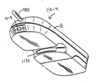
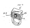
本発明によるモジュール構成で達成可能な大幅な小型化により、モジュールは、小型の機器または装置ハウジングに容易に取り付け可能とされて、その中にモジュールが実装された光学読取装置となる。本発明によるモジュールは、例えば、ピストル型読取装置ハウジング、携帯情報端末(PDA)、ポータブル・データ・ターミナル(PDT)、携帯電話、計算機、腕時計、指装着型“リングスキャナ”、ペンなどの筆記具、及び数々の他の装置に取り付けることができる。   Due to the significant miniaturization achievable with the module configuration according to the present invention, the module can be easily attached to a small instrument or device housing, resulting in an optical reader with the module mounted therein. The module according to the present invention includes, for example, a writing instrument such as a pistol-type reader housing, a personal digital assistant (PDA), a portable data terminal (PDT), a mobile phone, a computer, a wristwatch, a finger-mounted “ring scanner”, a pen, And can be attached to numerous other devices.

本発明のこれら及び他の側面については、以下に列挙した図面、及び本発明の詳細な説明を参照して本明細書中でさらに詳しく説明される。   These and other aspects of the invention are described in further detail herein with reference to the drawings listed below and the detailed description of the invention.

本発明の説明は、以下の8つの標題、すなわち(A)一般的な撮像モジュール構成および組立、(B)照射システム、(C)照準システム、(D)照射装置構造、(E)照射/照準発色の制御および調整、(F)受光光学部品、(G)素子の実装、(H)適用例、動作環境、及び制御回路の機能性、に分けられる。上記の標題は本明細書中で議論される様々な論題を大まかに分けることのみを意図したもので、本発明の幾つかの特徴に関する記述は、場合によっては1つ以上の標題に含まれるということは理解されるであろう。   The description of the present invention includes the following eight titles: (A) General imaging module configuration and assembly, (B) Illumination system, (C) Aiming system, (D) Illuminator structure, (E) Illumination / sighting Color control and adjustment, (F) light receiving optical components, (G) mounting of elements, (H) application examples, operating environment, and control circuit functionality. The above headings are intended only to broadly divide the various topics discussed herein, and descriptions of some features of the present invention are sometimes included in one or more headings. It will be understood.

A.一般的な撮像モジュール構成および組立
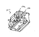
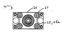
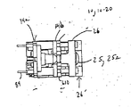
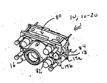
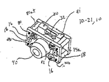
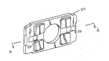
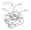
本発明による撮像モジュールの第1の実施例が、図1aないし図1gに示されている。撮像モジュール10(10−1)は、通常は画像センサチップによって提供される画像センサ32及び照準光源18を担持している第1の回路基板14aと、照射光源16を担持している第2の回路基板14bとを具備している。第1および第2の回路基板14aおよび14bは、支持アセンブリ80によって支持されている。モジュール10−1の支持アセンブリ80は、画像センサ32を格納するための格納部81と、レンズアセンブリ40を保持するための一体型保持部82とを具備している。モジュール10−1の支持アセンブリ80は第1の回路基板14aと第2の回路基板14bと共に、支柱84を受けるための柱穴83を有している。モジュール10−1はさらに4本の支柱84を具備し、その各々が第1の回路基板14a、支持アセンブリ80、および第2の回路基板14bを貫通して、モジュールの様々な構成要素を結合するのを助けている。撮像モジュール10−1は、様々な発光光学素子を担持する光学板26をさらに具備している。モジュール10−1の光学板26は、画像センサ32の視野に対応する対象領域の上にほぼ均一な照明パターンを展開するのを助けるための照射光学部品27、28(図1n参照)と、対象領域に照準パターンを投影するを助けるための照準光学部品25を具備している。第2の回路基板14bと光学板はいずれも、それらが支持アセンブリ80の方に移動された場合に保持部82を収容するための中央開口836、837を具備している。上述した構成により、撮像モジュールの実質的な小型化が得られる。モジュール10−1は、約0.810インチの幅寸法、約0.450インチの高さ寸法、および約0.560インチの奥行寸法を有することができる。モジュール10−1の照準および照射光源16、18は、側部に延在するリード線を有する、すなわち“ガルウイング型の”表面実装・背面ベンチLEDによって提供される。
A. General Imaging Module Configuration and Assembly A first embodiment of an imaging module according to the present invention is shown in FIGS. 1a to 1g. The imaging module 10 (10-1) normally includes a first circuit board 14a carrying the image sensor 32 and the aiming light source 18 provided by the image sensor chip, and a second carrying the irradiation light source 16. Circuit board 14b. The first and second circuit boards 14 a and 14 b are supported by a support assembly 80. The support assembly 80 of the module 10-1 includes a storage portion 81 for storing the image sensor 32 and an integrated holding portion 82 for holding the lens assembly 40. The support assembly 80 of the module 10-1 has a column hole 83 for receiving the column 84, together with the first circuit board 14a and the second circuit board 14b. Module 10-1 further includes four struts 84, each of which penetrates first circuit board 14a, support assembly 80, and second circuit board 14b to couple the various components of the module. Is helping. The imaging module 10-1 further includes an optical plate 26 that carries various light-emitting optical elements. The optical plate 26 of the module 10-1 includes illumination optics 27, 28 (see FIG. 1n) to assist in developing a substantially uniform illumination pattern over the target area corresponding to the field of view of the image sensor 32, the target Aiming optics 25 are provided to help project the aiming pattern onto the area. Both the second circuit board 14b and the optical plate are provided with central openings 836, 837 for receiving the holding portion 82 when they are moved toward the support assembly 80. With the configuration described above, the imaging module can be substantially reduced in size. Module 10-1 may have a width dimension of about 0.810 inches, a height dimension of about 0.450 inches, and a depth dimension of about 0.560 inches. The aiming and illuminating light sources 16, 18 of the module 10-1 are provided by side-extending leads, ie “gull-wing” surface mount and back bench LEDs.

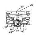
撮像モジュール10−1のさらなる側面について、図1hないし図1nを参照して説明する。図1hには、組立て前の状態のモジュール10−1の構成要素を図示する組立図が示されている。図1hから、第1の回路基板14aが画像センサチップによって提供される画像センサ32と、LEDによって提供される一対の照準光源18とを担持していることが分かる。モジュール10−1の支持アセンブリ80は格納部81を備えており、これは図1kの内面図に最もよく示されているように、画像センサ32を格納するための格納部を提供して画像センサの損傷を防ぎ、漂遊光線が画像センサ32に届かないようにしている。支持アセンブリ80はさらに、レンズアセンブリ40を保持するための一体型保持部82を具備しており、これについては明細書中でさらに詳細に説明する。支持アセンブリ80のさらなる側面について言及すると、モジュール10−1の支持アセンブリ80は、先に述べた柱穴83がその中に形成されている一体型ストラット80stと、照準パターンの形成を助けるための開口43とを備えており、これについては明細書中でさらに詳細に説明される。さらに、図1iに示されるように、支持アセンブリ80は、携帯型光学読取装置ハウジング、PDA、PDT、あるいは携帯電話などの内部に配置された部材など、モジュール10−1の外部部材に撮像モジュール10−1を取り付けるのを助けるための一体型取付ウイング80wを具備することができる。第2の回路基板14bと光学板26はそれぞれ、保持器82を収容するための中央開口836、837を備えている。取付ウイング80wは、取付ねじを受け入れるためのねじ穴810を備えている。ねじ穴810は、図1hに表示されているように支持アセンブリ本体に設けることもできる。図1iの実施例における支持アセンブリ80は、収容部81、保持部82、ストラット80st、照準開口43、および取付ウイング80wからなる一体型ユニットである。   Further aspects of the imaging module 10-1 will be described with reference to FIGS. 1h to 1n. FIG. 1h shows an assembly diagram illustrating the components of module 10-1 in a pre-assembled state. From FIG. 1h, it can be seen that the first circuit board 14a carries an image sensor 32 provided by an image sensor chip and a pair of aiming light sources 18 provided by LEDs. The support assembly 80 of module 10-1 includes a storage 81, which provides a storage for storing the image sensor 32, as best shown in the interior view of FIG. 1k. The stray light beam does not reach the image sensor 32. The support assembly 80 further includes an integral holding portion 82 for holding the lens assembly 40, as will be described in more detail in the specification. Referring to further aspects of the support assembly 80, the support assembly 80 of the module 10-1 includes an integral strut 80st in which the previously described post hole 83 is formed and an opening to assist in the formation of the aiming pattern. 43, which will be described in more detail in the specification. In addition, as shown in FIG. 1i, the support assembly 80 is connected to the imaging module 10 on an external member of the module 10-1, such as a portable optical reader housing, a PDA, a PDT, or a member disposed inside a mobile phone or the like. One-piece mounting wings 80w can be provided to help mount -1. The second circuit board 14b and the optical plate 26 are provided with central openings 836 and 837 for accommodating the holder 82, respectively. The mounting wing 80w includes a screw hole 810 for receiving a mounting screw. Screw holes 810 can also be provided in the support assembly body as shown in FIG. 1h. The support assembly 80 in the embodiment of FIG. 1i is an integrated unit comprising a receiving portion 81, a holding portion 82, a strut 80st, an aiming opening 43, and a mounting wing 80w.

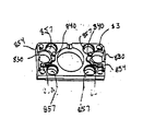
図1h、1j、1k、1Lをともに参照すると、プリント回路基板14a、支持アセンブリ80、プリント回路基板14b、および光学板26のそれぞれが、隣接する1つまたは複数の構成部品の相補形キー構造と噛合する複数のキー構造を有していることが分かる。特に、第1の回路基板14aは、支持アセンブリ80のくさびピン814を受ける一対のキー開口812を具備している。支持アセンブリ80の前方端部816もまた、くさびピン820を具備しており、該ピンは第2の回路基板14bのキー開口822によって噛合するよう受け入れられる。第2の回路基板14bは、光学板26のくさび側方ピン830を受けるための側方キー開口826と、光学板26のくさび中央ピン840を受けるための中央キーホール834とをさらに具備している。図1jおよび図1iに最もよく示されているくさび中央ピン840は、プリント回路基板14bのキーホール834をまっすぐ貫通し、支持アセンブリ80のキーホール842によって受けられる。ここで説明された様々なキー構造は、モジュール10−1の様々な構成部品を適切に位置合せするのを助け、これらの構成部品を組立てた後の、モジュール10−1の構成部品間のXY面におけるずれ量を大幅に減少させる。モジュール10−1は、モジュール10−1の構成部品間において適切なZ方向離間を得られるようにする素子をさらに具備している。図1hに見られるように、支持アセンブリ80は、支持アセンブリ80を第2のプリント回路基板14bと適切に離間するのを助けるための一対の上部および底部一体型スペーサリッジ846を具備している。支持部80の開口画定部材848は、アセンブリ80と基板14bの間を適切に離間するのを助けるように、隆起されて平らにされている。光学板26もまた、様々な離間支援部材を備えている。詳細に述べると、光学板26はスペーサリング852とスペーサリッジ854を具備している。スペーサリング852とスペーサリッジ854は、光学板26をプリント回路基板14bの方に押した場合に板26と基板14bの間に適切な離間が得られるようなサイズおよび構成とされている。モジュールの構成要素間の適切なZ方向離間は、支柱リングスペーサの使用、および/または後に述べるステップの助けにより実行することができる。モジュール10−1のさらなる側面について言及すると、板28は、LED16を受ける空洞部857を備えている。LED16を受けることによって、空洞部857はモジュール10−1の奥行寸法をさらに減少させる。ここで述べた撮像モジュールは大抵の場合、二次元画像センサを支持するものとして示されるが、本明細書に記載される撮像モジュールの構成は1D画像センサを支持するためのにも有効であることは理解されるであろう。   Referring to FIGS. 1h, 1j, 1k, and 1L together, each of the printed circuit board 14a, the support assembly 80, the printed circuit board 14b, and the optical board 26 includes a complementary key structure of one or more adjacent components. It can be seen that it has a plurality of meshing key structures. In particular, the first circuit board 14 a includes a pair of key openings 812 that receive the wedge pins 814 of the support assembly 80. The front end 816 of the support assembly 80 also includes a wedge pin 820, which is received to mate with the key opening 822 in the second circuit board 14b. The second circuit board 14b further includes a side key opening 826 for receiving the wedge side pin 830 of the optical plate 26 and a center keyhole 834 for receiving the wedge center pin 840 of the optical plate 26. Yes. The wedge center pin 840 best shown in FIGS. 1 j and 1 i passes straight through the keyhole 834 of the printed circuit board 14 b and is received by the keyhole 842 of the support assembly 80. The various key structures described herein help to properly align the various components of module 10-1, and after assembling these components, the XY between the components of module 10-1. The amount of displacement on the surface is greatly reduced. The module 10-1 further includes an element that makes it possible to obtain an appropriate Z-direction separation between the components of the module 10-1. As seen in FIG. 1h, the support assembly 80 includes a pair of top and bottom integrated spacer ridges 846 to assist in properly separating the support assembly 80 from the second printed circuit board 14b. The opening defining member 848 of the support 80 is raised and flattened to assist in proper separation between the assembly 80 and the substrate 14b. The optical plate 26 also includes various separation assisting members. More specifically, the optical plate 26 includes a spacer ring 852 and a spacer ridge 854. Spacer ring 852 and spacer ridge 854 are sized and configured to provide an appropriate separation between plate 26 and substrate 14b when optical plate 26 is pushed toward printed circuit board 14b. Appropriate Z-direction separation between the components of the module can be performed with the use of strut ring spacers and / or the steps described below. Referring to further aspects of module 10-1, plate 28 includes a cavity 857 that receives LED 16. By receiving the LED 16, the cavity 857 further reduces the depth dimension of the module 10-1. The imaging modules described here are often shown as supporting a two-dimensional image sensor, but the configuration of the imaging module described herein is also effective for supporting a 1D image sensor. Will be understood.

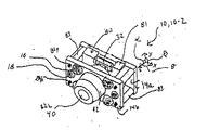
本発明による撮像モジュール10−1の変形例が図2aに示されている。モジュール10−1と同様に、図2aないし図2cの実施例におけるモジュール10−2は、支持アセンブリ80、第1の回路基板14a、第2の回路基板14b、および上記の構成要素を構造的に支持するための支柱84を具備している。しかしながらモジュール10−2は、モジュール10−1のようにレンズプレート26を備えるものではない。さらに、モジュール10−1とは異なり、モジュール10−2は表面実装LEDを備えており、LEDのダイはプリント回路基板に直接付着されている。図2a〜図2dに示されるモジュール10−2の照準LED18および照明LED16は、表面実装LEDによって提供される。図2aの実施例における支持アセンブリ80は、バレル型保持部82と、格納部81とを具備している。保持部82は、レンズバレルに組み込まれる単一素子または多素子結像レンズを具備することのできるレンズアセンブリ40を保持している。格納部81は画像センサ32を格納しており、これについては本明細書中でさらに詳細に説明する。支持アセンブリ80は、プリント回路基板14aおよび回路基板14bをベンチングできるストラット80stをさらに具備している。アセンブリ80のストラット80stはモジュール10−1と同様に、アセンブリ80の残りの構成要素と一体に形成されることができる、あるいはストラット80stはモジュール10−2に示すようにアセンブリ構成要素、例えば81および82とは別個に形成してもよい。モジュール10−2は、本明細書に記載されるように光学板26が無いものとして図示されている。光学板26によって提供される機能は、モジュール10−2に組み込まれていない部材(読取装置ハウジング111の部材など)によってその全部または一部を提供されることができる、あるいは光学板26の機能は、明細書中で後に説明するようにその全部または一部をモジュールの光源16、18に直接的に組み込んでもよい。   A modification of the imaging module 10-1 according to the invention is shown in FIG. 2a. Similar to module 10-1, module 10-2 in the embodiment of FIGS. 2a-2c structurally includes support assembly 80, first circuit board 14a, second circuit board 14b, and the components described above. A support 84 is provided for support. However, the module 10-2 does not include the lens plate 26 unlike the module 10-1. Further, unlike module 10-1, module 10-2 includes a surface mounted LED, and the LED die is attached directly to the printed circuit board. The aiming LED 18 and the illumination LED 16 of the module 10-2 shown in FIGS. 2a-2d are provided by surface mounted LEDs. The support assembly 80 in the embodiment of FIG. 2 a includes a barrel type holding part 82 and a storage part 81. The holder 82 holds a lens assembly 40 that can comprise a single element or multi-element imaging lens that is incorporated into the lens barrel. The storage unit 81 stores the image sensor 32, which will be described in more detail in this specification. The support assembly 80 further includes a strut 80st that can bench the printed circuit board 14a and the circuit board 14b. The struts 80st of the assembly 80 can be formed integrally with the remaining components of the assembly 80, similar to the module 10-1, or the struts 80st can be assembled with assembly components such as 81 and as shown in the module 10-2. It may be formed separately from 82. Module 10-2 is illustrated as having no optical plate 26 as described herein. The function provided by the optical plate 26 can be provided in whole or in part by a member (such as a member of the reader housing 111) that is not incorporated in the module 10-2, or the function of the optical plate 26 is All or part of it may be incorporated directly into the light sources 16, 18 of the module, as will be described later in the specification.

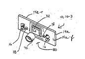
モジュール10のさらなる変形例が図2eおよび図2fに示されている。図2eの実施例では、撮像モジュール10−3は、図1a(モジュール10−1)や図2a(モジュール10−2)に示す第1および第2PCBの代わりに、単一のPCB14aを具備している。表面実装される照準LED18および照射LED16はPCB14の前方面14a−fに取り付けられ、処理回路、例えば制御回路140、またはその一部はPCB14aの後方面14a−rに取り付けられている。図2eの実施例における格納部81およびレンズバレル40を保持するための保持部82を備えた支持アセンブリ80は、図2fに示したのと同様の全体構成アセンブリ80を有することができる。   A further variation of the module 10 is shown in FIGS. 2e and 2f. In the embodiment of FIG. 2e, the imaging module 10-3 comprises a single PCB 14a instead of the first and second PCBs shown in FIG. 1a (module 10-1) and FIG. 2a (module 10-2). Yes. Surface-mounted aiming LEDs 18 and illumination LEDs 16 are attached to the front face 14a-f of the PCB 14, and processing circuitry, for example the control circuit 140, or part thereof, is attached to the rear face 14a-r of the PCB 14a. The support assembly 80 with the storage 81 and the holding portion 82 for holding the lens barrel 40 in the embodiment of FIG. 2e can have an overall assembly 80 similar to that shown in FIG. 2f.

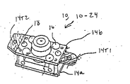
本発明による撮像モジュールの別の変形例が図2fに示されている。図2fに示すモジュール10−4(10)の実施例において、支柱84は、モジュール10の構成部品を固定するためにPCBと支持アセンブリ80のねじ穴83tにねじ込まれる、ねじ山付きねじ84tによって置き換えられている。表面実装照射および照準LED16、18を有するPCB14bは、一対のPCB14b1及び14bを背面実装されたPCBとすることができる平面部材14pの図示される組合せによって置き換えることができ、PCB14b1と14b2はそれぞれ本明細書中に記載されるような表面実装照射LED16と表面実装照準LED18を具備していることがさらに分かる。もちろん、明細書中で図示し説明した表面実装LEDのいずれかを、例えば、明細書中に記載されるような従来のリード型LED、表面実装LED、側面リード型表面実装LEDに置き換えてもよい。   Another variant of the imaging module according to the invention is shown in FIG. In the embodiment of module 10-4 (10) shown in FIG. 2f, the strut 84 is replaced by a threaded screw 84t that is screwed into a screw hole 83t in the PCB and support assembly 80 to secure the components of the module 10. It has been. The PCB 14b with the surface mounted illumination and aiming LEDs 16, 18 can be replaced by the illustrated combination of planar members 14p, where the pair of PCBs 14b1 and 14b can be back mounted PCBs, each PCB 14b1 and 14b2 being described herein. It can further be seen that it comprises a surface mount illumination LED 16 and a surface mount aiming LED 18 as described in the document. Of course, any of the surface mount LEDs shown and described in the specification may be replaced with, for example, conventional lead type LEDs, surface mount LEDs, side lead type surface mount LEDs as described in the specification. .

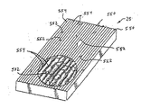
図2gの実施例において、モジュール10−5は、モジュール10−1と同様に、回路基板14bの前方に搭載され、支柱84で支持された光学板26を具備している。図2gのモジュール10−5に具備されるようなタイプの光学板26について、図5d、5e、及び5fを参照して明細書中でさらに詳細に説明する。図2gに示すような光学板26は、複数の概ね円柱のマイクロレンズ及び相互接続部を具備することができ、これについては図5dないし図5fを参照してさらに詳細に説明される。図2gに示す光学板26は、円柱レンズ25cによって提供される照準光学部品25をその内部に組み込むこともできる。後でさらに詳細に説明するように、例えば図1h、1g、1m、6m、及び6qに示すような開口43を照準LED18の前方に設けることができ、例えばレンズ25は、照準線または他の照準パターンが対象領域T上に投影されるように、開口を通る光が対象領域T上で結像するように構成されることができる。図2gの実施例の光学板26は、図1aのモジュール10−1に示すように、各照射LED用の個別の拡散器27を有する光学板と置き換えることができる。明細書の他(例えば図1n、2o、及び図5gないし図5k)で説明するように、光学板26は、対象領域Tの角に光を向けるための、光入射面または出射面上に形成されたウェッジ28を有することができる。   In the embodiment of FIG. 2g, the module 10-5 includes the optical plate 26 that is mounted in front of the circuit board 14b and supported by the support column 84, like the module 10-1. An optical plate 26 of the type as provided in module 10-5 of FIG. 2g will be described in more detail in the specification with reference to FIGS. 5d, 5e and 5f. The optical plate 26 as shown in FIG. 2g may comprise a plurality of generally cylindrical microlenses and interconnects, which will be described in further detail with reference to FIGS. 5d-5f. The optical plate 26 shown in FIG. 2g can also incorporate the aiming optical component 25 provided by the cylindrical lens 25c therein. As will be described in more detail later, an aperture 43 as shown, for example, in FIGS. The light passing through the aperture can be configured to image on the target region T so that the pattern is projected onto the target region T. The optical plate 26 of the embodiment of FIG. 2g can be replaced with an optical plate having a separate diffuser 27 for each illuminated LED, as shown in module 10-1 of FIG. 1a. As described elsewhere in the specification (eg, FIGS. 1n, 2o, and FIGS. 5g-5k), the optical plate 26 is formed on a light incident or exit surface for directing light to the corners of the target region T. Can be provided with a wedge 28.

撮像モジュールの別の変形例が図2hに示されており、図2hのモジュール10−6(10)によって示されるように柱84をさらに延長することによって、支柱穴83を組み込んだ付加的な部材を撮像モジュール10に実装することができる。例えば、モジュール10−1またはモジュール10−6の光学板26に組み込まれる光学部品は、1つ以上の部材にわたって分散されることができる。モジュール10−6に示されるように、第1の光学板26、860は拡散器27などの照射光学部品を担持することができ、第2の光学板26、862は円柱レンズ25などの照準光学部品を担持することができる。後にさらに詳細に説明するように、拡散器27は、例えば屈折型光学素子マイクロレンズ、回折型レンズ、または負レンズのような任意の適切なタイプとすることができる。モジュール10−6は、モジュール10上に積み重ねられた付加的な前方部材862に加え、付加的な後方部材14pを具備している。付加的な後方部材14pは、例えば、モジュール10−6の温度を下げるために用いられる放熱板として用いられる、熱は通すが電気的に絶縁された部材などとすることができる、あるいは部材14pは、例えば付加的な回路構成要素を担持するためのプリント回路基板とすることができる。   Another variation of the imaging module is shown in FIG. 2h, with additional members incorporating the post holes 83 by further extending the post 84 as shown by module 10-6 (10) of FIG. 2h. Can be mounted on the imaging module 10. For example, the optical components incorporated in the optical plate 26 of the module 10-1 or module 10-6 can be distributed over one or more members. As shown in module 10-6, the first optical plates 26 and 860 can carry illumination optical components such as a diffuser 27, and the second optical plates 26 and 862 are aiming optics such as a cylindrical lens 25. Parts can be carried. As will be described in more detail later, the diffuser 27 may be of any suitable type, such as a refractive optical element microlens, a diffractive lens, or a negative lens. Module 10-6 includes an additional rear member 14p in addition to an additional front member 862 stacked on module 10. The additional rear member 14p can be, for example, a member that is used as a heat sink used to lower the temperature of the module 10-6, that is a member that allows heat to pass but is electrically insulated, or the member 14p is For example, a printed circuit board for carrying additional circuit components.

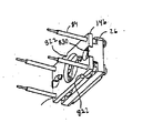
モジュール10−6のさらなる側面を参照すると、モジュール10−6の支柱84は、リングスペーサ84rを具備している。リングスペーサ84rは支柱84に一体化されることができる、あるいはリングスペーサ84rは、支柱84に嵌合可能なプラスチックスリーブからなるものでもよいし、あるいはシングスペーサ84rは、支柱84pに機械加工されたスロットにスナップ嵌合される部材からなるものであってもよい。リングスペーサ84rは、モジュール10の積層される部材を適切に離間させるのを助ける。例えばモジュール10−1、10−2、10−5、および10−6の支柱84に主に関連する本発明の特徴について、ここで詳細に説明する。モジュール10−1を参照して説明された各ストラット80stには、支柱84を収容するための支柱穴83が形成されている。上記の柱格納モジュールのいずれにおいても、各支柱84は、対応する柱穴83に摩擦嵌めされるが実質的に摺動可能とすることができる。代替例では、各支柱84は、対応する穴83の内部にしっかりと取り付けることもできる。支持アセンブリ80は、支柱84pをアセンブリ80に対してしっかりと固定するために、支柱84pにオーバーモールドすることもできる。回路基板14a及び14bもまた、支柱84pを収容するための柱穴83を有している。回路基板14a及び14bの穴14hは、明細書中でさらに詳細に説明されるように、支柱84hに対して、穴14hがモジュール10a−1の様々な構成要素を適切に位置合せするのに役立つように形成される。ストラット80stは非常に有効であることが分かっているが、モジュール10のサイズを小さくするためにストラット80stを取り除くこともできることが分かる。図1vの実施例では、一体化された長型ストラット80stを有する支持部80が示されている。長型支柱80stは、例えばストラット80stが柱84にオーバーモールドされ、ストラット80st内の固定位置に支柱をしっかりと固定することが望ましい場合に有益であろう。   Referring to a further aspect of module 10-6, the post 84 of module 10-6 includes a ring spacer 84r. The ring spacer 84r can be integrated with the column 84, or the ring spacer 84r can be made of a plastic sleeve that can be fitted to the column 84, or the single spacer 84r has been machined into the column 84p. It may consist of a member snap-fitted into the slot. The ring spacer 84r helps to properly separate the stacked members of the module 10. For example, features of the present invention that relate primarily to the struts 84 of modules 10-1, 10-2, 10-5, and 10-6 will now be described in detail. Each strut 80 st described with reference to the module 10-1 is formed with a support hole 83 for accommodating the support 84. In any of the above-described column storage modules, each column 84 is frictionally fitted into the corresponding column hole 83 but can be substantially slidable. In the alternative, each strut 84 can be securely mounted within the corresponding hole 83. The support assembly 80 can also be overmolded to the struts 84p in order to secure the struts 84p to the assembly 80. The circuit boards 14a and 14b also have a column hole 83 for accommodating the column 84p. The holes 14h in the circuit boards 14a and 14b help the hole 14h properly align the various components of the module 10a-1 with respect to the post 84h, as will be described in more detail herein. Formed as follows. While the strut 80st has been found to be very effective, it can be seen that the strut 80st can be removed to reduce the size of the module 10. In the embodiment of FIG. 1v, a support 80 is shown having an integrated long strut 80st. The long strut 80st may be beneficial, for example, when the strut 80st is overmolded to the pillar 84 and it is desirable to securely fix the strut in a fixed position within the strut 80st.

モジュール10を組み立てるための一方法によれば、支柱84は、アセンブリ80から外方向に延在するように支持アセンブリ80の様々な穴に挿入される。それから、プリント回路基板14a及び14bは、回路基板14a及び14bの柱穴83が支柱84を収容するように、支柱84pの露出した部分の上に置かれる。本発明のある実施例では、画像センサを担持する回路基板14aの支柱穴83は、支柱84の直径よりかなり大きくすることができる。回路基板14bの穴83を支柱84よりかなり大きくすれば、回路基板14aをアセンブリ80のある位置に固定する前に、回路基板14aの位置をX、Y、およびZ方向において支持アセンブリ80に対して細かく調整することができるようになる。穴83が支柱84よりもかなり大きくされている場合、回路基板14aは、アセンブリ80に対して回路基板14bを固定する前に、アセンブリ80に対するある位置に動かしながら傾斜させたり回転移動させたりできる。モジュール、例えば10−1、10−2、10−5、及び10−6を組み立てる人は、ビデオモニタを利用して位置合せ処理に役立てることができる。モジュール10は、ビデオモニタ、例えば“証印制御画像解析モードを有する撮像装置”というタイトルで2001年9月17日に出願され、参照によって本明細書に引用される出願第09/954,081にさらに詳しく説明されているようなホストコンピュータシステム(例えばパーソナルコンピュータ)ビデオモニタに表示可能な画像を取り込むように作動されることができる。モジュール10は、高精密印刷証印を備える対象物(例えばドル紙幣)の画像を取り込むようになされてもよく、ユーザは、モニタに表示された表示画像が良好なものとなるまで、組立て中のモジュールの構成要素を調整することができる。アセンブリ80に対する回路基板14aの固定は、はんだを用いて行うことができる。回路基板14aの支柱穴83が、幾つかの限られら側面においては支柱84と同様に作動する支持構造よりもかなり大きく作られている実施例に関する更なる説明は、“光学および画像センササブアセンブリの位置合せおよび取付方法”というタイトルで1999年5月17日に出願され、参照によって本明細書に引用される同時係属中の出願第09/312,479号で述べられている。画像センサ32の位置をレンズアセンブリ40に対して細かく調整する必要がない場合は、回路基板14aの柱穴83は、支柱84に対して摩擦嵌めされるのに都合のよいサイズとされる。   According to one method for assembling the module 10, the struts 84 are inserted into various holes in the support assembly 80 so as to extend outwardly from the assembly 80. The printed circuit boards 14a and 14b are then placed on the exposed portion of the post 84p such that the post holes 83 in the circuit boards 14a and 14b receive the post 84. In one embodiment of the present invention, the post hole 83 of the circuit board 14a carrying the image sensor can be significantly larger than the diameter of the post 84. If the hole 83 in the circuit board 14b is made much larger than the post 84, the position of the circuit board 14a is relative to the support assembly 80 in the X, Y, and Z directions before the circuit board 14a is secured to a position in the assembly 80. It will be possible to make fine adjustments. If the hole 83 is significantly larger than the post 84, the circuit board 14a can be tilted or rotated while being moved to a position relative to the assembly 80 before the circuit board 14b is secured to the assembly 80. Those who assemble modules, such as 10-1, 10-2, 10-5, and 10-6, can utilize a video monitor to assist in the alignment process. Module 10 is described in further detail in application 09 / 954,081, filed Sep. 17, 2001, entitled “Imaging Device with Indicium Controlled Image Analysis Mode”, for example, and incorporated herein by reference. A host computer system (eg, a personal computer) such as those that can be activated to capture images that can be displayed on a video monitor. Module 10 may be adapted to capture an image of an object (e.g., dollar bill) with a high precision printing indicia, and the user is assembling the module until the displayed image displayed on the monitor is good. The components of can be adjusted. The circuit board 14a can be fixed to the assembly 80 using solder. A further description of an embodiment in which the post hole 83 in the circuit board 14a is made considerably larger than the support structure that operates in some limited aspects similar to the post 84 is described in “Optical and Image Sensor Subassemblies”. No. 09 / 312,479, filed May 17, 1999, entitled “Registration and Mounting Methods” and incorporated herein by reference. When it is not necessary to finely adjust the position of the image sensor 32 with respect to the lens assembly 40, the column hole 83 of the circuit board 14 a has a size that is convenient for friction fitting with the column 84.

本明細書中に記載される支柱84を具備するモジュールの更なる側面について言及すると、支柱84は導電性にされて、支柱84が第1の回路基板14aと第2の回路基板14bの電気回路間に電気通信を確立するようにモジュール10内に配置されるのが好ましい。回路基板14bは照射LED16と、ある場合には照準LED18を具備し、動作するためにはいずれも電力が必要である。回路基板14aは、後に明細書中で説明するように、画像センサ32と、ある場合には照準LED18と、画像センサ32に関連した何らかの電気回路とを担持している。画像センサ32に関連する処理回路は、回路基板14aの前面14a−f及び/または背面14a−r上に取り付けることができる。支柱84が構造的な支持と、第1および第2の回路基板14a及び14bの回路構成要素間における電気通信の両方を提供するようにモジュール10を構成することによって、空間節約という重要な利点が得られ、さらに構造的な支持と電気通信を得るために別々の構造部材(例えば、基板14aと基板14bとの間を接続するためのフレックス接続などを含む)をモジュール10に配置する場合に予想されるよりも、モジュール10を小さくすることができる。   Referring to a further aspect of the module comprising the post 84 described herein, the post 84 is made conductive so that the post 84 is an electrical circuit of the first circuit board 14a and the second circuit board 14b. It is preferably arranged in the module 10 so as to establish telecommunications in between. The circuit board 14b includes an illumination LED 16 and, in some cases, an aiming LED 18, and both require power to operate. The circuit board 14a carries the image sensor 32, in some cases the aiming LED 18, and some electrical circuitry associated with the image sensor 32, as will be described later in the specification. Processing circuitry associated with the image sensor 32 can be mounted on the front surface 14a-f and / or the back surface 14a-r of the circuit board 14a. By configuring the module 10 such that the struts 84 provide both structural support and electrical communication between the circuit components of the first and second circuit boards 14a and 14b, an important advantage of space saving is obtained. Expected when placing separate structural members (including, for example, a flex connection for connecting between the substrate 14a and the substrate 14b) in the module 10 to obtain further structural support and telecommunications. The module 10 can be made smaller than is done.

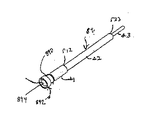
柱格納モジュール、例えば10−1、10−7と共に使用しうるタイプの支柱のさらなる側面について、図1rに示す支柱84の分解組立図を参照して説明する。図1rの実施例における支柱84は、突刺部890と、段s1、s2、及びs3によって画定される段状パターンと、別の支柱84の段s3が開放端894に摩擦嵌めまたは滑り嵌めできるようなサイズにされた開放端894を有する先端部892とからなる。   Further aspects of a post of the type that may be used with post storage modules such as 10-1, 10-7 will be described with reference to an exploded view of the post 84 shown in FIG. 1r. The strut 84 in the embodiment of FIG. 1r has a stepped pattern defined by the piercing portion 890, steps s1, s2, and s3, so that the step s3 of another strut 84 can be friction fit or slip fit on the open end 894. And a tip 892 having an open end 894 that is sized.

支柱84の突刺部890は、接着性物質やはんだなど何らかの外部固定剤を用いることなく、モジュール、例えば10−1の組立ての際に光学板26のある位置に支柱84を摩擦保持できるようにする。   The piercing portion 890 of the column 84 can frictionally hold the column 84 at a position where the optical plate 26 is located when the module, for example, 10-1, is assembled without using any external fixing agent such as an adhesive substance or solder. .

段s1、s2、及びs3によって規定される支柱84の段状パターンによって、モジュール、例えば10−1の何らかの構成要素にスペーサ要素を設ける必要がなくなる。もちろん、段、例えばs1、s2、及びs3は、スペーサ、例えば878と組み合わせて使用することもできる。図1oを参照すると、開口板610は、第1および第2の段s1とs2の間のリッジr12に対してベンチングできることが分かる。さらに、図2iないし図2kを参照すると、付加的なPCB14cまたは他の構造を、支柱84pの第2および第3の段s2及びs3の間に画定された支柱84のリッジr23に対してベンチングできることが分かるであろう。   The stepped pattern of struts 84 defined by steps s1, s2, and s3 eliminates the need to provide spacer elements on some components of the module, for example 10-1. Of course, the steps, such as s1, s2, and s3, can also be used in combination with a spacer, such as 878. Referring to FIG. 1o, it can be seen that the aperture plate 610 can be benched against the ridge r12 between the first and second stages s1 and s2. 2i-2k, additional PCB 14c or other structure can be benched against the ridge r23 of the strut 84 defined between the second and third stages s2 and s3 of the strut 84p. You will understand.

読取装置110において必要な回路構成要素の全て、または本質的に全て、あるいはほぼ全てが単一のPCB、例えばPCB14bに担持されるように、PCB14bが高度に集積された回路構成要素を具備しているのが好ましいことを本明細書において後で説明する。しかしながら、付加的なスペースが利用可能な適用では、回路構成要素の全体的なコストを下げるために、読取装置110に大きな回路構成要素を低集積度で実装し、回路基板を担持する1つ以上の大きな回路構成要素上に回路構成要素を分散させるのが望ましいかもしれない。支柱84は、特に図1rに示すように構成された場合、回路の構成要素が幾つかの基板にわたって分散され、モジュールがそれでもコンパクトで概ね立方の構造を保持できるようなモジュール構成を容易にすることができる。先に示したように、付加的な回路基板14cをリッジr23に対してベンチングすることができる。さらに、付加的な支柱84aの開放端894は支柱84に嵌合させることができ、さらに別の回路基板、例えばPCB14d、または複数の基板を前記付加的な支柱に嵌合させることができる。支柱84は導電性にすることができるので、モジュール10aの複数の回路基板間における電気的通信を支柱84によって得ることができる。従って支柱84は、回路基板間に必要な導電性経路の数が支柱84の数以下である場合に、空間を消費する電気コネクタ、例えばフレックス帯状レセプタクルなどをモジュール10の1つ以上の回路基板、例えば14a、14b、及び14cに実装する必要をなくすものである。   PCB 14b comprises highly integrated circuit components such that all, essentially all, or nearly all of the circuit components required in reader 110 are carried on a single PCB, eg, PCB 14b. This is explained later in this specification. However, in applications where additional space is available, one or more carrying large circuit components in the reader 110 with low integration and carrying circuit boards to reduce the overall cost of the circuit components. It may be desirable to distribute circuit components over large circuit components. The strut 84, particularly when configured as shown in FIG. 1r, facilitates a module configuration in which the circuit components are distributed across several substrates and the module can still retain a compact and generally cubic structure. Can do. As previously indicated, an additional circuit board 14c can be benched against the ridge r23. Further, the open end 894 of the additional strut 84a can be mated to the strut 84, and another circuit board, such as a PCB 14d, or multiple boards can be mated to the additional strut 84. Since the support 84 can be made conductive, electrical communication between the circuit boards of the module 10a can be obtained by the support 84. Thus, the struts 84 can be used to connect space-consuming electrical connectors, such as flex strip receptacles, to one or more circuit boards of the module 10 when the number of conductive paths required between the circuit boards is less than or equal to the number of struts 84. For example, it is not necessary to mount on 14a, 14b, and 14c.

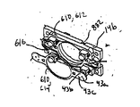
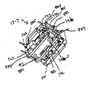
本発明の主にモジュール10aの組立てに関連するさらなる側面について、図1oないし図1uを参照して説明する。図1oは、図1aないし図1gに関連して議論されたモジュール10−1と同様のモジュール10−7に対応する組立図を示している。モジュール10−7では、支持アセンブリ80にではなく、非一体型開口板610に開口43が画定されている。モジュール10−7を組み立てるための一方法によれば、導電性支柱84がまず光学板26に取り付けられ、それからプレート610が取り付けられている一体型PCB14bを有するアセンブリ870が支柱84に取り付けられる。次に、支持アセンブリ80と、LED18(通常のリード型LEDとして示されている)が取り付けられたPCB14aとを具備するアセンブリ872が支柱84上に取り付けられ、支柱84がPCB14aにはんだ付けされる。図1uに最もよく示されているように、インタフェース885では、後でさらに詳細に説明するが、モジュールの構成要素を一体型ユニットとして一緒に固定するために、支柱84と基板14bの間のインタフェース884にはんだを加えて、モジュール10−7の構成要素をさらに固定し、支柱84と基板14b間の電気的接続が必要であれば、そのような接続を設けることができる。最後に、レンズバレルによって提供されるレンズアセンブリ40がアセンブリ80の保持部82に挿入され、細密調整され、以下でさらに詳しく説明するような方法で保持部82に固定される。モジュール10−1を組み立てるための組立て処理は、プレート26と支柱84を一体にしたものを、PCB14bと開口板610を具備するアセンブリではなくPCB14bに取付けることができることを除いては、ほぼ同じであることが分かるであろう。   Further aspects of the present invention primarily relating to the assembly of the module 10a will be described with reference to FIGS. FIG. 1o shows an assembly view corresponding to module 10-7 similar to module 10-1 discussed in connection with FIGS. 1a-1g. In module 10-7, an opening 43 is defined in the non-integral aperture plate 610, not in the support assembly 80. According to one method for assembling the module 10-7, the conductive post 84 is first attached to the optical plate 26, and then the assembly 870 having the integrated PCB 14 b to which the plate 610 is attached is attached to the post 84. Next, an assembly 872 comprising a support assembly 80 and a PCB 14a with an LED 18 (shown as a normal lead type LED) is mounted on the post 84 and the post 84 is soldered to the PCB 14a. As best shown in FIG. 1u, interface 885, which will be described in more detail later, provides an interface between strut 84 and substrate 14b to secure the module components together as an integral unit. If solder is added to 884 to further secure the components of the module 10-7 and such an electrical connection between the post 84 and the substrate 14b is required, such a connection can be provided. Finally, the lens assembly 40 provided by the lens barrel is inserted into the holding portion 82 of the assembly 80, finely adjusted, and secured to the holding portion 82 in a manner that will be described in more detail below. The assembly process for assembling the module 10-1 is substantially the same except that the integrated plate 26 and post 84 can be attached to the PCB 14b rather than the assembly comprising the PCB 14b and the aperture plate 610. You will understand.

モジュール10−7のさらなる側面について言及すると、モジュール10−7はモジュール10−1と同様に、図2gの実施例のモジュール10−5によって示されるような単一の拡散パターンではなく、光学板26上に複数の個別の拡散パターン27を具備する。さらに、モジュール10−7では、モジュール10−5およびモジュール10−1と同様に、光学板26の最前面が照準光学部品25の放射面によって定義される面よりも前方に位置することが分かる。拡散器27によって定義される面が光学部品25によって定義される面よりも前になるように光学板26上における光学部品25の位置決めをすることによって、モジュール10の使用中、または読取装置のハウジングへの取付けの際にモジュール10−1、10−7が様々な物体と偶発的または不注意により接触することによって起こりうる損傷から光学部品25を守ることができる。モジュール10の照準システムが光学部品25の欠陥の影響を受けるよりも、モジュール10の照射システムが光学部品27の欠陥の影響を受ける方が少ないので、光学部品25ではなく光学部品27が接触する可能性が高くなるように光学板26−1を設計することが有効である。   Referring to further aspects of module 10-7, module 10-7, like module 10-1, is not a single diffusion pattern as shown by module 10-5 of the embodiment of FIG. A plurality of individual diffusion patterns 27 are provided on the top. Furthermore, in the module 10-7, it can be seen that the forefront surface of the optical plate 26 is located in front of the surface defined by the radiation surface of the aiming optical component 25, as in the modules 10-5 and 10-1. By positioning the optical component 25 on the optical plate 26 so that the surface defined by the diffuser 27 is ahead of the surface defined by the optical component 25, the module 10 is in use or the reader housing. The optical component 25 can be protected from damage that may occur when the modules 10-1, 10-7 come into contact with various objects accidentally or inadvertently during mounting. Since the illumination system of the module 10 is less affected by the defect of the optical component 27 than the aiming system of the module 10 is affected by the defect of the optical component 25, the optical component 27 can contact instead of the optical component 25. It is effective to design the optical plate 26-1 so as to improve the performance.

任意のモジュール、例えばモジュール10−1、10−2、10−3、10−4、10−5、10−6、及び10−7に組み込むことができる別のモジュール構成要素について、図1p及び図1qを参照して説明する。図1pの部分的に組み立てられたモジュールでは、支持アセンブリ80がLED保持部876を具備している。LED保持部876は、PCB14aを支柱84に取り付ける前にLED18をPCB14aにはんだ付けする必要がなくなるよう、組立て処理の間にLED18を所定の位置に保持する。すなわち、LED18をPCB14aにはんだ付けしなくても、組立工は、支持アセンブリ80、LED18、PCB14aを組合せたものを組立工程の間に手で一緒に保持し、これらの部品の組合せを支柱84の上に配置し、一回のはんだ付けステップでLED18を支柱84とPCB14aの両方にはんだ付けしてモジュールの構成要素を互いに固定することができる。図1p及び図1qに示す支持アセンブリ80のさらなる側面として、保持アセンブリ80はスペーサ878及び880を具備している。アセンブリ80のスペーサ878は、支持部80とPCB14bの間に間隔をあける。スペーサ880(1つのみ図示)は、PCB14bの嵌合的に係合するキーホール882に対する一体型くさびピンを具備している。支持アセンブリ80とPCB14bの間に間隔をあけるために、支柱格納ストラット80stではなくスペーサ878、880、及び846、848(モジュール10−1)を使用することにより、図1uに最もよく示されるように、支柱84とPCB14bの背面14b−rの間に露出した界面884が定義されることになる。モジュール、例えば10−1、10−7の組立ての際に、モジュール、例えば10−1、10−7の構成要素を結合する機械的保持力を補強し、かつPCB14bと支柱84の間の電気的接触を強めるために、これらの界面884にはんだ付けすることができる。図1oの実施例では、照準LED18は従来のリード型LEDによって提供されているが、照射LED16は以下でさらに十分に説明するように側面リード型表面実装・背面ベンチングLEDによって提供されている。   For other module components that can be incorporated into any module, such as modules 10-1, 10-2, 10-3, 10-4, 10-5, 10-6, and 10-7, FIG. This will be described with reference to 1q. In the partially assembled module of FIG. 1p, the support assembly 80 includes an LED holder 876. The LED holder 876 holds the LED 18 in place during the assembly process so that it is not necessary to solder the LED 18 to the PCB 14a before attaching the PCB 14a to the post 84. That is, even if the LED 18 is not soldered to the PCB 14a, the assembler holds the combination of the support assembly 80, the LED 18, and the PCB 14a together by hand during the assembly process, and the combination of these components Arranged above, the components of the module can be secured together by soldering the LED 18 to both the post 84 and the PCB 14a in a single soldering step. As a further aspect of the support assembly 80 shown in FIGS. 1p and 1q, the retaining assembly 80 includes spacers 878 and 880. FIG. The spacer 878 of the assembly 80 provides a space between the support 80 and the PCB 14b. Spacer 880 (only one shown) includes an integral wedge pin for matingly engaged keyhole 882 of PCB 14b. By using spacers 878, 880, and 846, 848 (module 10-1) instead of strut storage struts 80st to provide spacing between support assembly 80 and PCB 14b, as best shown in FIG. The exposed interface 884 is defined between the column 84 and the back surface 14b-r of the PCB 14b. During assembly of the modules, such as 10-1, 10-7, the mechanical retention force that couples the components of the modules, such as 10-1, 10-7, is reinforced and the electrical connection between the PCB 14b and the post 84 These interfaces 884 can be soldered to enhance contact. In the embodiment of FIG. 1o, the aiming LED 18 is provided by a conventional lead type LED, while the illumination LED 16 is provided by a side lead type surface mount / back benching LED as will be described more fully below.

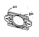
図1qは、開口板610の別の実施例を示している。図1qに示す開口板610は、プレート部612と開口インサート部614からなる2部材アセンブリである。プレート部612は、所望の照準パターンがモジュール10によって投影されるようにモジュール10内の所望の位置に開口部614を位置合せして受けるようになされた形状のリセス616を具備している。開口部614は、リセス616内に受け入れられ、接着剤および/または摩擦力によって所定の位置に固定される。開口インサート部614は、金属からなることが好ましい。開口部614を形成する際に使用する材料として金属を選択することにより、開口43a、43b、及び43cをかなり小さなサイズに、かつ厳密に管理されたサイズおよび形状に製作することができるようになる。図1p及び図1qの両方の開口板610は、PCB14bのキー構造882に係合するためのキー構造886を具備している。   FIG. 1 q shows another embodiment of the aperture plate 610. The aperture plate 610 shown in FIG. 1q is a two-member assembly comprising a plate portion 612 and an aperture insert portion 614. The plate portion 612 includes a recess 616 shaped to receive the opening 614 in alignment with a desired position in the module 10 so that a desired aiming pattern is projected by the module 10. Opening 614 is received in recess 616 and secured in place by adhesive and / or frictional forces. The opening insert portion 614 is preferably made of metal. By selecting metal as the material to be used in forming the opening 614, the openings 43a, 43b, and 43c can be made to a fairly small size and precisely controlled size and shape. . Both aperture plates 610 of FIGS. 1p and 1q include a key structure 886 for engaging the key structure 882 of the PCB 14b.

ここで図2Lに示すモジュール10−8を参照する。モジュール10−8の照準LED18は、モジュール10−9のLED18(リード型LED)よりもかなり低い高さ寸法を有する。従って、開口43を照準光源18に対して物理的に可能限り近くに配置することが通常好まれるので、図2Lの実施例における開口43は、モジュール10−7の開口43よりもPCB14aの近くに配置されるであろう。PCBaの表面近くに照準開口を位置決めするために、図2Lのモジュール10−8及びモジュール10−1(図1h)によって示される保持アセンブリ80の実施例に示すように、開口43は支持アセンブリ80上に設けることができる。図2Lの実施例では、シュラウド80shが開口43から前方に延在している。シュラウド80shは、スペーサ80spによって提供される間隔開け機能を補強するためにスペーサ80spの高さに合ったサイズにすることができる。   Reference is now made to module 10-8 shown in FIG. 2L. The aiming LED 18 of the module 10-8 has a considerably lower height dimension than the LED 18 (lead type LED) of the module 10-9. Accordingly, since it is usually preferred to place the opening 43 physically as close as possible to the aiming light source 18, the opening 43 in the embodiment of FIG. 2L is closer to the PCB 14a than the opening 43 of the module 10-7. Will be placed. In order to position the aiming opening near the surface of the PCBa, the opening 43 is on the support assembly 80 as shown in the embodiment of the holding assembly 80 shown by module 10-8 and module 10-1 (FIG. 1h) of FIG. Can be provided. In the embodiment of FIG. 2L, a shroud 80 sh extends forward from the opening 43. The shroud 80sh can be sized to fit the height of the spacer 80sp to reinforce the spacing function provided by the spacer 80sp.

本発明による撮像モジュールの別の実施例が図2mないし図2pに示されている。モジュール10−1と同様に、撮像モジュール10−9は特に、バーコード読取装置、光学式文字認識(OCR)読取装置、バーコードとOCRの両方の読取能力を有する読取装置、携帯情報端末、ビデオカメラ、デジタルカメラ、携帯電話、または医療用目視検査機器などの撮像装置において使用するために設計されている。   Another embodiment of an imaging module according to the invention is shown in FIGS. 2m to 2p. Similar to module 10-1, imaging module 10-9 specifically includes a barcode reader, an optical character recognition (OCR) reader, a reader having both barcode and OCR reading capabilities, a personal digital assistant, a video Designed for use in imaging devices such as cameras, digital cameras, mobile phones, or medical visual inspection equipment.

例えばモジュール10の構成要素を支持するための支柱84を具備するモジュール10−1とは異なり、モジュール10−9は、撮像システムの電気的構成要素および光学的構成要素の両方を収容するようになされた搭載枠12を具備している。搭載枠12は、格納部81と保持部82をさらに有するモジュール10−9の一体集積型支持アセンブリ80の一部である。搭載枠12は、プリント回路基板(PCB)14aなどの回路基板、照射LED16、照準LED18、開口板610、及び光学板26を収容する。   Unlike module 10-1, which includes a post 84, for example, to support the components of module 10, module 10-9 is adapted to accommodate both the electrical and optical components of the imaging system. The mounting frame 12 is provided. The mounting frame 12 is a part of the integrated integrated support assembly 80 of the module 10-9 that further includes a storage portion 81 and a holding portion 82. The mounting frame 12 accommodates a circuit board such as a printed circuit board (PCB) 14a, an irradiation LED 16, an aiming LED 18, an aperture plate 610, and an optical plate 26.

さらに詳細に説明すると、支持アセンブリの枠体12は、背面板30と、上方側壁31および側方側壁31’からなる側壁を具備している。背面板30は、ソリッドステートの画像センサチップ32を受けるための凹んだ格納部81と、リード型LED16および18によって提供される照射および/または照準光源のリード線38を受けるための複数のピンホール36とを具備している。支持アセンブリ80は、背面板30と一体に形成された、受光光学レンズアセンブリ40、例えばレンズバレルを受けるための保持部82をさらに備え、このレンズアセンブリは、以下でさらに詳細に説明されるように組立工程における任意のステップの前または後に、保持部82に取りつけることができる。   More specifically, the frame 12 of the support assembly includes a back plate 30 and side walls composed of an upper side wall 31 and side side walls 31 '. The backplate 30 has a recessed housing 81 for receiving the solid state image sensor chip 32 and a plurality of pinholes for receiving the illumination and / or aiming light source leads 38 provided by the lead LEDs 16 and 18. 36. The support assembly 80 further comprises a receiving optical lens assembly 40, eg, a holding portion 82 for receiving a lens barrel, integrally formed with the back plate 30, the lens assembly as described in more detail below. It can be attached to the holding part 82 before or after any step in the assembly process.

モジュール10−9を組み立てる際には、まずねじ56を用いてPCB14aを背面板30に取付け、開口13が露出されるように枠体12を配向する。PCB14aが背面板30に取り付けられると、PCB14aに担持される画像センサ32は、図示するように画像センサ32の形状と相補形状をした中央リセス格納部81によって受けられる。PCB14aを枠体12に取り付けた後、取付け工は照射LED16と照準LED18をPCB14aに取りつける。   When assembling the module 10-9, first, the PCB 14a is attached to the back plate 30 using the screws 56, and the frame 12 is oriented so that the opening 13 is exposed. When the PCB 14a is attached to the back plate 30, the image sensor 32 carried on the PCB 14a is received by a central recess storage 81 having a shape complementary to the shape of the image sensor 32 as shown. After the PCB 14a is attached to the frame body 12, the attachment worker attaches the irradiation LED 16 and the aiming LED 18 to the PCB 14a.

LED16及び18をPCB14aに取付けるためには、LED16及び18のリード線38を、背面板30とPCB14aの位置合せされたピンホール36および54を貫通するように押し込んだ後に、LED16及び18をPCB14aにはんだ付けする。LED16及び18のすべてを、はんだ付けする前にそれぞれ対応するピンホールに位置決めすることが好ましい。LED16及び18をはんだ付けする際には、PCB14aの背面14a−rは、組立工が簡単に触ることができるような向きにされなければならない。はんだ付けの間、LED16及び18がPCB14aに対してほぼ垂直な所望の向きのままでいるために、LED16及び18を受けるような形状にされた標準的に公知の取付具(図示せず)を、はんだ付け工程の間、LED16及び18に対して一時的に用いることができる。   In order to attach the LEDs 16 and 18 to the PCB 14a, the lead wires 38 of the LEDs 16 and 18 are pushed through the aligned pinholes 36 and 54 of the back plate 30 and the PCB 14a, and then the LEDs 16 and 18 are inserted into the PCB 14a. Solder. All of the LEDs 16 and 18 are preferably positioned in their corresponding pinholes before soldering. When soldering the LEDs 16 and 18, the back surface 14a-r of the PCB 14a must be oriented so that the assembler can easily touch it. During soldering, a standard known fixture (not shown) shaped to receive the LEDs 16 and 18 is provided so that the LEDs 16 and 18 remain in a desired orientation that is generally perpendicular to the PCB 14a. The LED 16 and 18 can be temporarily used during the soldering process.

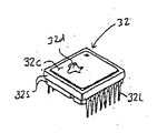
撮像モジュール10−9の重要な特徴は、LED16が完全に設置された時にLED16の背面の一部が画像センサ32の前面32fの一部に対向するように、照射LED16のリード線38が画像センサ32の側面32sに対してほとんど当接する関係で設置されるということである。この構成により、撮像モジュール12のサイズが縮小され、小サイズの光学読取装置に取り付け可能となる。   An important feature of the imaging module 10-9 is that when the LED 16 is completely installed, the lead wire 38 of the irradiation LED 16 is arranged so that a part of the back surface of the LED 16 faces a part of the front surface 32f of the image sensor 32. That is, it is installed so as to be almost in contact with the side surface 32s of 32. With this configuration, the size of the imaging module 12 is reduced and can be attached to a small-sized optical reader.

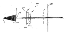
LED16及び18が上述したような方法でPCB14に取り付けられた後、照準LED18に嵌まるようなドーム42を有する開口板610が枠体12に取り付けられる。このドームは、スリット開口43を通ってドームを出る光以外は、照準LED18から発せられる全ての光を実質的にブロックするよう不透過であることが好ましい。スリット開口43は、所望の形状をした照準パターンの照射が対象Tに投影されるように形成されるべきである。ある実施例では、開口スリット43は、水平線パターンが対象上に投影されるように矩形形状にされる。   After the LEDs 16 and 18 are attached to the PCB 14 in the manner described above, an aperture plate 610 having a dome 42 that fits on the aiming LED 18 is attached to the frame 12. The dome is preferably opaque so as to substantially block all light emitted from the aiming LED 18 except for light exiting the dome through the slit opening 43. The slit opening 43 should be formed so that irradiation of the aiming pattern having a desired shape is projected onto the target T. In one embodiment, the aperture slit 43 is rectangular so that a horizontal line pattern is projected onto the object.

開口板610は、開口板が照射LED16の上に嵌まるようにするために隙間を提供する複数の切開部46を備えている。ドーム42と切開部46は、これらがLED16と接触しないように形成することができる。図示される実施例では、各LEDは、はんだ付けされる際に所望の方向に保持されるので、組立工程の間に背面板30の平坦な表面に対してLED基部17の平坦な面が圧迫される。さらなる側面において、開口板610は、LED16及び18によって伝送される光がモジュールの受光光学システムと干渉するのを防ぐためのシュラウド58を具備しており、このシュラウド58は背面板30と光学板26の間に適切な間隔を開けることを意図して構成してもよいことが分かる。   The aperture plate 610 includes a plurality of incisions 46 that provide gaps so that the aperture plate fits over the illuminated LED 16. The dome 42 and the incision 46 can be formed so that they do not contact the LED 16. In the illustrated embodiment, each LED is held in the desired orientation when soldered, so that the flat surface of the LED base 17 is pressed against the flat surface of the backplate 30 during the assembly process. Is done. In a further aspect, the aperture plate 610 includes a shroud 58 for preventing light transmitted by the LEDs 16 and 18 from interfering with the receiving optical system of the module, and the shroud 58 includes the back plate 30 and the optical plate 26. It can be seen that it may be configured with the intention of providing an appropriate interval between the two.

開口板610がLED16及び18の上に配置され背面板30の方に移動された後に、光学板26が枠体12の開口13にスナップ嵌めされる。光学板26は、照射LEDから放出される光を拡散するための拡散器27を具備している。その前面に拡散器27が形成されていることに加え、光学板26は、その内側面にさらにウェッジ28が形成されている。ウェッジ28は、LED16からの光を対象Tの角の方に向けて対象の照射の一様性を向上させている。さらに詳細に説明されるように、拡散器27は様々な形態をとることができ、光学板26の光入射面上に形成されることができる。さらに、ウェッジ28を光学板26の光出射面上に形成してもよい。   After the aperture plate 610 is placed over the LEDs 16 and 18 and moved toward the back plate 30, the optical plate 26 is snapped into the aperture 13 of the frame 12. The optical plate 26 includes a diffuser 27 for diffusing light emitted from the irradiation LED. In addition to the diffuser 27 formed on the front surface, the optical plate 26 further has a wedge 28 formed on the inner surface thereof. The wedge 28 directs the light from the LED 16 toward the corner of the target T to improve the uniformity of irradiation of the target. As will be described in more detail, the diffuser 27 can take various forms and can be formed on the light incident surface of the optical plate 26. Further, the wedge 28 may be formed on the light emitting surface of the optical plate 26.

フック状端部49を有する弾性フィンガ部48が枠体12の上方または側方側壁31に形成されて、光学板26を枠体12にスナップ嵌めできるようにしている。図示される実施例では、弾性フィンガ部48を引っ張り、光学板を背面板30の方に押し、それからフィンガ部48を放して光学板26をモジュール10内の所定の位置にロックすることによって、光学板26を枠体12にスナップ嵌めすることができる。光学板とフィンガ部は、光学板26が背面板30の方に押されると、フィンガ部が光学板26によって広げられ開放されるように形成することができる。完全に組み立てられると、モジュール10−9は、約19mm(0.75インチ)の高さ寸法、約39mm(1.5インチ)の幅寸法、及び約27mm(1.06インチ)の奥行寸法を有することができる。   Elastic finger portions 48 having hook-like end portions 49 are formed above the frame body 12 or on the side wall 31 so that the optical plate 26 can be snapped onto the frame body 12. In the illustrated embodiment, the optical finger portion 48 is pulled, the optical plate is pushed toward the back plate 30, and then the finger portion 48 is released to lock the optical plate 26 in place within the module 10. The plate 26 can be snapped onto the frame 12. The optical plate and the finger portion can be formed such that when the optical plate 26 is pushed toward the back plate 30, the finger portion is spread and opened by the optical plate 26. When fully assembled, the module 10-9 has a height dimension of about 19 mm (0.75 inch), a width dimension of about 39 mm (1.5 inch), and a depth dimension of about 27 mm (1.06 inch). Can have.

光学読取装置の必要な電気回路のほぼ全体を単一のプリント回路基板に実装できるようにするために、枠体の背面板30の裏面は、PCB14aの前面14a−fから前方向に延びる電気構成要素を収容するように構成してもよい。従って、背面板30の裏面は、ソリッドステートの画像センサ32を位置合せし受容するための中央リセス34と、PCB14aの前面から突出しうる構成要素および/または導線などの電気回路802を収容するための周辺リセス35とを具備することが分かる。開口板610は、光学板26が枠体12にスナップ嵌めされると開口板24を背面板30の方に圧迫するように作用するスペーサ52を具備している。モジュール10−9のスペーサ52はさらに、フィンガ部48によって光学板26に付与された力を開口板610に移して、接着剤や、ねじまたはピンなどの外部の機械的固定手段を使用することなく、開口板610と光学板26の両方を枠体12内において固定する。図2nの実施例では、光学板26は、各照射LED16に対する個別の拡散器27を具備している。図5dの別の実施例では、単一の拡散器27が、光学板26の表面のほぼ全体にわたって形成されている。   In order to allow almost all of the necessary electrical circuitry of the optical reader to be mounted on a single printed circuit board, the back side of the frame back plate 30 has an electrical configuration extending forward from the front side 14a-f of the PCB 14a. You may comprise so that an element may be accommodated. Accordingly, the back side of the backplate 30 is for receiving a central recess 34 for aligning and receiving the solid state image sensor 32 and an electrical circuit 802 such as components and / or conductors that can protrude from the front side of the PCB 14a. It can be seen that a peripheral recess 35 is provided. The aperture plate 610 includes a spacer 52 that acts to press the aperture plate 24 toward the back plate 30 when the optical plate 26 is snapped onto the frame 12. The spacer 52 of the module 10-9 further transfers the force applied to the optical plate 26 by the finger 48 to the aperture plate 610 without using an adhesive or external mechanical fastening means such as screws or pins. Both the aperture plate 610 and the optical plate 26 are fixed in the frame body 12. In the embodiment of FIG. 2n, the optical plate 26 comprises a separate diffuser 27 for each illuminated LED 16. In another embodiment of FIG. 5d, a single diffuser 27 is formed over substantially the entire surface of the optical plate.

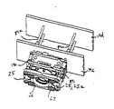
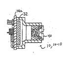
図3aないし図3dの実施例におけるモジュール10の更なる変形例について言及すると、撮像モジュール10−10は、その上に画像センサ32と照射LED16の両方が取り付けられたプリント回路基板14aを具備している。一対のLEDが画像センサ32の両側に取り付けられて、ほぼ直線的に並べられた4つのLEDからなるLEDパターンを形成している。水平向きの直線パターンでLEDを取付けることによって、モジュール10−9やモジュール10−1と比べてモジュール10−10の高さ寸法要件が減少する。LEDを水平向きの直線パターンで取付けることにより、モジュール10−2の高さを画像センサ32の高さに近い高さまで減少させることができる。モジュール10−10のさらなる側面について言及すると、モジュール10−10はPCB14に取り付けられた、またはPCB14から延在する支持アセンブリ80を具備している。図3aないし図4d及び図4kないし図4nに示される各実施例の支持アセンブリ80は、収容部81と保持部82とを具備している。収容部81は画像センサ32を収容し、保持部82はレンズアセンブリ40を保持する。保持部82はまた、LED16から直接放射される光線をはじめとして対象における画像に対応しない光線が、画像センサ32に到達するのを防ぐ。   Referring to a further variation of module 10 in the embodiment of FIGS. 3a-3d, imaging module 10-10 comprises a printed circuit board 14a on which both image sensor 32 and illumination LED 16 are mounted. Yes. A pair of LEDs are attached to both sides of the image sensor 32 to form an LED pattern composed of four LEDs arranged substantially linearly. By mounting the LEDs in a horizontal linear pattern, the height dimension requirements of module 10-10 are reduced compared to modules 10-9 and 10-1. By mounting the LEDs in a horizontal linear pattern, the height of the module 10-2 can be reduced to a height close to that of the image sensor 32. Referring to a further aspect of module 10-10, module 10-10 includes a support assembly 80 attached to or extending from PCB. The support assembly 80 of each embodiment shown in FIGS. 3 a to 4 d and FIGS. 4 k to 4 n includes a receiving portion 81 and a holding portion 82. The accommodating portion 81 accommodates the image sensor 32, and the holding portion 82 holds the lens assembly 40. The holding unit 82 also prevents light rays not directly corresponding to the image in the object, including light rays emitted directly from the LED 16, from reaching the image sensor 32.

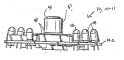
本発明による撮像モジュールのさらなる変形例について言及すると、図3eないし図3hの実施例において、撮像モジュール10−11は、その上に画像センサチップ32と、照射LED16と、照準LED18とが搭載されたプリント回路基板14aを具備する。3つのLEDがモジュール10−11の両側に搭載されていて、6つのLEDからなる水平向きのほぼ直線パターンのLEDを形成している。内側のLED18は照準LEDで、外側のLED16は照射LEDである。照射LED16は、対象領域の中央が付加的な照射光学部品がなくても、より均一に照射されるよう、図3hに最もよく示されるように傾斜される(ある角度で取り付けられる)ことができる。   Referring to a further modification of the imaging module according to the present invention, in the embodiment of FIGS. 3e to 3h, the imaging module 10-11 is mounted with the image sensor chip 32, the illumination LED 16 and the aiming LED 18 thereon. A printed circuit board 14a is provided. Three LEDs are mounted on both sides of the module 10-11 to form a horizontal LED having a substantially linear pattern of six LEDs. The inner LED 18 is an aiming LED, and the outer LED 16 is an illumination LED. The illumination LED 16 can be tilted (attached at an angle) as best shown in FIG. 3h so that the center of the target area is illuminated more evenly without additional illumination optics. .

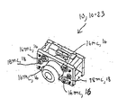
撮像モジュールのさらなる変形例が図3iないし図3mに示されている。図3iのモジュール10−12では、支持アセンブリ80の形状が変更されており、アセンブリ80はボックス型で、ほぼ等しい高さ、幅、及び奥行とされている。ボックス型の収容および保持アセンブリ80は、特に回路基板14とほぼ等しい高さとなるようなサイズにされた場合、ある実装上の利点が得られる。例えばアセンブリ80が機器のハウジングの平坦な表面に当接するようにモジュール10−12を機器ハウジング内に取り付けた場合、ボックス型アセンブリ80は、モジュール10−12の安定化に役立つ。図3jに示すモジュール10−13は、図示されるようにリード型LEDが表面実装LED16及び18と置き換えられていることを除いては、モジュール10−12とほぼ同様な構造を備えている。ここに述べるリード型LEDは、図3jに示すような表面実装LED、側面リード型表面実装LED、または表面組込み型LEDと通常は置き換え可能であることを理解すべきである。   Further variations of the imaging module are shown in FIGS. 3i to 3m. In the module 10-12 of FIG. 3i, the shape of the support assembly 80 has been changed so that the assembly 80 is box-shaped and has approximately equal height, width, and depth. The box-type containment and retention assembly 80 provides certain mounting advantages, particularly when sized to be approximately the same height as the circuit board 14. For example, when the module 10-12 is mounted in the equipment housing such that the assembly 80 abuts the flat surface of the equipment housing, the box-type assembly 80 helps to stabilize the module 10-12. The module 10-13 shown in FIG. 3j has substantially the same structure as the module 10-12 except that the lead type LEDs are replaced with surface mount LEDs 16 and 18 as shown. It should be understood that the lead-type LEDs described herein can usually be replaced with surface-mounted LEDs, side-leaded surface-mounted LEDs, or surface-embedded LEDs as shown in FIG. 3j.

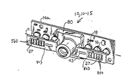
モジュール10−10、10−11、10−12、及び10−13は、機器ハウジング111の個別の部材に取付けられた照射光学部品と組み合せて用いることができる。あるいは、照射光学部品を、図3k、図3L、図3mのモジュール10−14、10−15、及び10−16によって図示されるようなモジュールに組み込んでもよい。図3kのモジュール10−14は、照射LED16に摩擦嵌めされるようになされた形状適合拡散器504、27を具備している。図3Lおよび図3mに示す実施例では、モジュール10−15、10−16は、アセンブリ80から外方向に延在する光学フランジ803を具備している。各フランジ803は、照準LED18からの光を形成するためのスリット開口43と、照射LED16からの光を拡散させるための拡散器27とを具備することができる。拡散器27は、プレートインサート560の一部としてフランジ803内に成型してもよい。フランジ803は、一体型収納・保持・フランジアセンブリを製造するのに適したモールドを用いて支持アセンブリ80と一体形成してもよい。フランジ84は、PCB14aまたはモジュールが設置される機器ハウジングの部材に取付けることもできる。図3mに示すモジュール10−16は、リード型LEDが図示されるような表面実装LED16及び18と置き換えられることを除いては、モジュール10−15と同様である。さらに、モジュール10−16のフランジ803は、PCB14aに対してモジュール10−15のフランジ803よりも短い距離だけ離して配置されている。   Modules 10-10, 10-11, 10-12, and 10-13 can be used in combination with illumination optics attached to individual members of equipment housing 111. Alternatively, the illumination optics may be incorporated into a module as illustrated by modules 10-14, 10-15, and 10-16 of FIGS. 3k, 3L, and 3m. The module 10-14 of FIG. 3k includes conformable diffusers 504, 27 that are adapted to be friction fitted to the illumination LED 16. In the embodiment shown in FIGS. 3L and 3m, modules 10-15, 10-16 include an optical flange 803 extending outwardly from assembly 80. FIG. Each flange 803 can comprise a slit opening 43 for forming light from the aiming LED 18 and a diffuser 27 for diffusing the light from the illuminating LED 16. The diffuser 27 may be molded into the flange 803 as part of the plate insert 560. The flange 803 may be integrally formed with the support assembly 80 using a mold suitable for manufacturing an integral storage / holding / flange assembly. The flange 84 can also be attached to a member of the equipment housing where the PCB 14a or module is installed. Module 10-16 shown in FIG. 3m is similar to module 10-15 except that the lead-type LEDs are replaced with surface mount LEDs 16 and 18 as shown. Further, the flange 803 of the module 10-16 is disposed away from the PCB 14a by a shorter distance than the flange 803 of the module 10-15.

モジュール10−15の拡散器27は、拡散器27を具備する光学部材の光放射面上に形成された、水平向きのほぼ円筒形マイクロレンズを含むタイプのものとして図示されている。明細書中でさらに詳細に説明するが、ほぼ円筒形のマイクロレンズは、マイクロレンズの向きに対して好ましくは横方向に光を拡散するように作用する。こうして、直線的に並べられた照射LED16を有するモジュール10−15の拡散器27の水平向きマイクロレンズは、直線的に並べられた光源のセットを用いて生成される照射パターン全体の高さ寸法を大きくするように作用することになる。   The diffuser 27 of the module 10-15 is illustrated as a type that includes a horizontally oriented generally cylindrical microlens formed on the light emitting surface of the optical member comprising the diffuser 27. As will be described in more detail herein, the generally cylindrical microlens acts to diffuse light, preferably transversely to the microlens orientation. Thus, the horizontally oriented microlens of the diffuser 27 of the module 10-15 having linearly arranged illumination LEDs 16 can provide a height dimension for the overall illumination pattern generated using a linearly arranged set of light sources. It will act to make it bigger.

別の撮像モジュールが図4aないし図4dに示されている。モジュール10−17において、フレキシブルプリント回路基板14aは、画像センサチップ32と、光源の位置312から、該光源位置から離れた光管遠位端314に光を伝達するための光管310とを担持している。モジュール10−17の光管310は、光ファイバケーブルによって提供されるものとして図示されている。しかしながら、光管は、成型された光管であってもよい。光ファイバケーブルは、ミネソタ州WayzataのSchott Corp.やカリフォルニア州IrvineのBivaropto Inc.など幾つかの製造業者から入手可能である。光管310は任意の長さとすることができ、モジュール10−17のフレキシブル回路基板14aの実質的に任意の位置に取付けることができる。このモジュール10−17の構造によれば、モジュール10−17を多種多様な機器ハウジングおよび装備に設置することができるようになることが分かるであろう。モジュール10−17のミネソタ州MinneapolisのMincro Inc.から入手できるタイプのフレキシブル回路基板14aは、事実上、無限の形に曲げられて多様な形状およびサイズの機器ハウジングにモジュールの10−17を取付け可能とするものである。さらに、光管310は、遠位端314が対象に向けられると、空間消費型LEDを撮像軸の周りに何らかの配置で取付けることを必要とせずに対象領域Tを照射する。光管310を撮像モジュール10−17に組み込むことの重要な利点は、個々の光管の遠位端314によって消費されるスペースを増やすことなく、個々の光管によって放射される照射のラジアンスを増すことができるということである。光管の遠位端314にて放射される光のラジアンスは、1つ以上の光源からの光を光管の光源端312に向けることによって増加することができる。光管の光源端は、図4eによって示されるように2つ以上の光入射部312a及び312bに分割することができ、その各々はLEDなどの光源の近傍に配置される。さらに光管は、図4f、4i、及び4jに示すように1つ以上の光源からの光を受光できるような、より大きな光源端および直径を持つようになされることができる。   Another imaging module is shown in FIGS. 4a to 4d. In the module 10-17, the flexible printed circuit board 14a carries the image sensor chip 32 and the light tube 310 for transmitting light from the light source position 312 to the light tube distal end 314 remote from the light source position. is doing. The light tube 310 of the module 10-17 is illustrated as being provided by a fiber optic cable. However, the light tube may be a molded light tube. Fiber optic cables are available from several manufacturers, including Schott Corp. in Wayzata, Minnesota and Bivaropto Inc. in Irvine, California. The light tube 310 can be of any length and can be mounted at substantially any location on the flexible circuit board 14a of the module 10-17. It will be appreciated that the structure of this module 10-17 allows the module 10-17 to be installed in a wide variety of equipment housings and equipment. A flexible circuit board 14a of the type available from Mincro Inc. of Minneapolis, Minnesota, module 10-17, can be bent into an infinite shape to mount module 10-17 in equipment housings of various shapes and sizes. It is what. In addition, the light tube 310 illuminates the target region T without requiring any space-consuming LED to be mounted in any arrangement around the imaging axis when the distal end 314 is directed at the target. An important advantage of incorporating the light tube 310 into the imaging module 10-17 is that it increases the radiance of the radiation emitted by the individual light tube without increasing the space consumed by the distal end 314 of the individual light tube. Is that you can. The radiance of light emitted at the distal end 314 of the light tube can be increased by directing light from one or more light sources to the light source end 312 of the light tube. The light source end of the light tube can be divided into two or more light entrances 312a and 312b, as shown by FIG. 4e, each of which is located near a light source such as an LED. Further, the light tube can be made to have a larger light source end and diameter so that it can receive light from one or more light sources as shown in FIGS. 4f, 4i, and 4j.

ここで図4gないし図4jを参照して、成型された光管311を有する撮像モジュール10−18について説明する。モジュール10−18では、PCB14aは撮像軸a1に対して平行に配置され、画像センサチップ32はPCB14a上に垂直に取付けられている。画像センサ32は、剛性のフレックスPCBを用いることによってPCB14a上に垂直に取付けることができる。モジュール10−18のさらなる側面について言及すると、表面実装型LEDによって提供されるLED16および18がPCB14aに取付けられ、LED16及び18からの光が、光管の遠位端314を通って対象Tに向かうよう撮像軸a1に対してほぼ平行な方向に向けられるように、成型された光管がLED16s及び18sに関連して配置される。成型光管311は、カリフォルニア州IrvinのBivaropto Inc.やニュージャージー州ManasquanのDialight Corp.などの製造業者から入手可能である。拡散器は、図4gに示す拡散器27によって示されるように、照射光管311、311iの遠位端に鋳込まれることができる。拡散器は、例えば回折型光学部品、屈折型光学部品(例えばマイクロレンズ)、または負レンズ拡散器などとすることができる。拡散器は、モジュール10−17の管310の遠位端314に形成することもできる。光ファイバケーブル光管の場合のように、任意の一つの成型光管311によって放出される照射のラジアンスは、図4gの光管311iによって示されるように、管311の光源端312を広くして1つ以上の光源からの光を集めるように光源端311を配置することによって、増加させることができる。図4jに示すモジュール10−18の照射光管311iは、3つの表面実装LED16からの光を集光するが、照準光管311aは単一の表面実装LED18からの光を集光する。 Here, an imaging module 10-18 having a molded light tube 311 will be described with reference to FIGS. 4g to 4j. In module 10-18, PCB 14a is disposed parallel to the imaging axis a 1, the image sensor chip 32 is mounted vertically on PCB 14a. The image sensor 32 can be mounted vertically on the PCB 14a by using a rigid flex PCB. Referring to a further aspect of module 10-18, LEDs 16 and 18 provided by surface mounted LEDs are attached to PCB 14a, and light from LEDs 16 and 18 is directed to object T through the distal end 314 of the light tube. get drunk be directed in a direction substantially parallel to the imaging axis a 1, the light pipe which is molded is placed in connection with LED16s and 18s. Molded light tubes 311 are available from manufacturers such as Bivaropto Inc., Irvin, Calif., And Dialight Corp., Manasquan, NJ. The diffuser can be cast at the distal end of the illumination tube 311, 311i, as shown by the diffuser 27 shown in FIG. 4g. The diffuser can be, for example, a diffractive optical component, a refractive optical component (eg, a microlens), a negative lens diffuser, or the like. A diffuser can also be formed at the distal end 314 of the tube 310 of the module 10-17. As in the case of a fiber optic cable light tube, the radiation radiance emitted by any one shaped light tube 311 widens the light source end 312 of the tube 311 as shown by the light tube 311i in FIG. 4g. This can be increased by placing the light source end 311 to collect light from one or more light sources. The irradiation light tube 311i of the module 10-18 shown in FIG. 4j condenses the light from the three surface mount LEDs 16, while the aiming light tube 311a condenses the light from the single surface mount LED18.

PCB14aを撮像軸a1に対して平行に配置し、PCB14aに対して平行な方向に光を向けるよう成型光管311をPCB14a上に取付けることによって、モジュール10の高さ寸法が減少し、高さ寸法の低い“薄い”機器ハウジング内へのモジュールの設置が容易になる。図4kないし図4nに示すモジュール10−19によって図示されるように、画像センサチップ32をPCB14aにバックマウントすることによって、光管照射を有する撮像モジュール10の高さ寸法をさらに減少させることができる。図4kないし図4nの実施例では、画像センサチップ32が、撮像軸a1をほぼ90度曲げるのに十分な折曲げ光学部品を備えた格納・保持アセンブリ80と共に、PCB14a上にバックマウントされている。折曲げ光学部品は、例えば破線で示された鏡404によって示されるように、壁402上にめっきされた反射性材料を形成したり、壁402に鏡を貼り付けたりすることによって設けられる。モジュール10−19は画像センサ32の幅よりも小さい高さ寸法を有するように設計できるので、モジュール10−19は、“薄い”読取装置ハウジングに実装するのにとりわけ好適である。例えば、モジュール10−14は、図9iに示すような携帯電話や図9jに示すようなハンディタイプのコンピュータなどの携帯情報端末“PDA”のハウジング内に実装するのに好適である。 By placing the PCB 14a parallel to the imaging axis a 1 and mounting the molded light tube 311 on the PCB 14a so as to direct light in a direction parallel to the PCB 14a, the height dimension of the module 10 is reduced and the height is increased. Easier installation of modules in low-profile “thin” equipment housings. As illustrated by the modules 10-19 shown in FIGS. 4k-4n, the height dimension of the imaging module 10 with light tube illumination can be further reduced by back mounting the image sensor chip 32 to the PCB 14a. . In the embodiment of FIGS. 4k-4n, the image sensor chip 32 is back-mounted on the PCB 14a with a storage and holding assembly 80 with folding optics sufficient to bend the imaging axis a 1 approximately 90 degrees. Yes. The fold optical component is provided by forming a plated reflective material on the wall 402 or by attaching a mirror to the wall 402, for example as indicated by the mirror 404 shown in broken lines. Because module 10-19 can be designed to have a height dimension that is less than the width of image sensor 32, module 10-19 is particularly suitable for mounting in a “thin” reader housing. For example, the module 10-14 is suitable for mounting in a housing of a portable information terminal “PDA” such as a mobile phone as shown in FIG. 9i or a handy type computer as shown in FIG. 9j.

B.照射
本発明による照射システムの特徴について、主に図5aないし図5fを参照してここで説明する。画像センサ32の視野に対応する全パターン520内の対象領域Tをほぼ均一に照射するために(コーナー部は、対象領域の最大明度の少なくとも約50%の明度に照射される)、2列に並べられた4LED照射システム(例えばモジュール10−1またはモジュール10−9のようなシステム)の各LEDから放射される光は、図5aに示すように線522によって実質的に定義される境界19を有する、ほぼ矩形の照射パターンを提供するように拡散されるべきである。
B. Illumination The features of the illumination system according to the present invention will now be described mainly with reference to FIGS. 5a to 5f. In order to irradiate the target region T in the entire pattern 520 corresponding to the field of view of the image sensor 32 substantially uniformly (the corner portion is irradiated at a brightness of at least about 50% of the maximum brightness of the target region) in two rows The light emitted from each LED of a side-by-side 4 LED illumination system (eg, a system such as module 10-1 or module 10-9) passes through a boundary 19 that is substantially defined by line 522 as shown in FIG. 5a. And should be diffused to provide a generally rectangular illumination pattern.

図5bには、例えばモジュール10−9(図2n)の多拡散器光学板26を製造する際に用いられるモールド526の表面が示されており、モールド526は別々に作られた回折型モールド素子528をその中に実装することができる。モールド526に実装されるモールド素子528は、カリフォルニア州TorranceのPhysical Optics Corp.やニューヨーク州RochesterのFresnel Opticsから入手できるようなホログラフィ技術を用いて製造されるタイプのものとしてもよい。拡散光学素子の他の製造業者としては、ノースカロライナ州CharlotteのDOC、アラバマ州HuntsvilleのMEMSや、ニューヨーク州RochesterのRPCなどがある。   FIG. 5b shows the surface of a mold 526 used, for example, in manufacturing the multi-diffuser optical plate 26 of module 10-9 (FIG. 2n), the mold 526 being a diffractive mold element made separately. 528 can be implemented therein. The mold element 528 mounted on the mold 526 may be of the type manufactured using holographic techniques such as those available from Physical Optics Corp. of Torrance, California and Fresnel Optics of Rochester, New York. Other manufacturers of diffusing optics include DOC in Charlotte, North Carolina, MEMS in Huntsville, Alabama, and RPC in Rochester, New York.

図5cには、例えば図2gのモジュール10−5に組み込まれたり、図5dの光学板26によって示されるような、単一拡散器光学板26を製造する際に用いられるモールド527の表面が示されている。モールド527は、その上にテクスチャが直接形成されている。このテクスチャは、酸レジスト処理により塗布することができる。オハイオ州PainsvilleのMold Tech Inc.などのモールドテクスチャリング会社は、図5eに示すようなテクスチャを有する表面を持つ部分を作るために用いられるモールド527のように、酸レジスト処理によりテクスチャをモールドに塗布することを専門にしている。本明細書中に記載される任意の実施例において光学板26を製造する際に用いるのに適した材料は、ポリカーボネイトである。   FIG. 5c shows the surface of a mold 527 that is used in manufacturing a single diffuser optical plate 26, for example incorporated in module 10-5 of FIG. 2g or as shown by optical plate 26 in FIG. 5d. Has been. The mold 527 has a texture directly formed thereon. This texture can be applied by acid resist treatment. Mold texturing companies such as Mold Tech Inc. in Painsville, Ohio, apply a texture to the mold by acid resist treatment, such as a mold 527 used to create a textured surface as shown in FIG. 5e. Specializing in doing. A suitable material for use in manufacturing the optical plate 26 in any of the embodiments described herein is polycarbonate.

図2pのテクスチャード面モールド527は、図5bの回折型拡散器モールド素子インサートを設けたモールドよりも、一般に安価でかつ耐久性がある。回折モールド素子528は、製造するの費用がかかる上、頻繁な交換が必要である。図5cに示すようなテクスチャードモールドは、一般に、指紋が付きにくい面を製造するなどの用途に用いられる。知られている限り、図5cに示すようなインサートレス・テクスチャード面モールドを用いて作られる光透過板は、主に光源の視野を覆い隠すために光源を有する製品に組み込まれてきたが、画像取り込みシステムの制御された対象領域照射を生むためには用いられてこなかった。   The textured surface mold 527 of FIG. 2p is generally cheaper and more durable than the mold with the diffractive diffuser mold element insert of FIG. 5b. The diffractive mold element 528 is expensive to manufacture and requires frequent replacement. A textured mold as shown in FIG. 5c is generally used for applications such as manufacturing a surface that is difficult to attach a fingerprint. As far as is known, light transmissive plates made using insertless textured surface molds as shown in FIG. 5c have been incorporated into products with a light source, primarily to obscure the field of view of the light source, It has not been used to produce controlled target area illumination for image capture systems.

幾つかのLEDからの光を拡散するための単一拡散器27を有する図5dの光学板26の拡散面を示す分解組立図が、図5e及び図5fに示されている。光学板26は、概ね隣接し概ね円筒形のマイクロレンズ550を複数備えている。マイクロレンズ550のさらなる側面について言及すると、これらのマイクロレンズ550は、光学板26上にランダムなパターンで形成されることが好ましく、同一サイズのマイクロレンズを特に要求することもなく、レンズ間の厳密な平行相対配向なしに、マイクロレンズ550が少なくとも2つの異なるサイズを持つことを特徴とするものである。パターンをランダム化することによって、対象領域Tにおける“ホットスポット”、すなわち一定の高ラジアンス照明が集中する領域の形成が減少する。光学板26の別の側面によれば、図5dに示すような光学板26は、様々な円柱マイクロレンズ550を区切る谷部分554に定められたクロスコネクション552を所々に備えることが好ましい。クロスコネクション552は、マイクロレンズ550によって得られる光の拡散方向に対してほぼ横方向の光の拡散を提供するもので、マイクロレンズ550は、典型的なモジュール/対象間読取距離(例えば通常の規則では、約1インチないし15インチ)において光線が互いに発散する関係となるように、光源16からの光線をレンズ550の前方に近接して位置する集束点に集束させることによって作動すると考えられる。   An exploded view showing the diffusing surface of the optical plate 26 of FIG. 5d with a single diffuser 27 for diffusing light from several LEDs is shown in FIGS. 5e and 5f. The optical plate 26 includes a plurality of generally adjacent microlenses 550 that are cylindrical. Referring to further aspects of the microlenses 550, these microlenses 550 are preferably formed in a random pattern on the optical plate 26, and there is no need for microlenses of the same size, and the exact size between the lenses. Without the parallel relative orientation, the microlens 550 has at least two different sizes. By randomizing the pattern, the formation of “hot spots” in the target area T, ie areas where constant high radiance illumination is concentrated, is reduced. According to another aspect of the optical plate 26, the optical plate 26 as shown in FIG. 5d preferably has cross-connections 552 defined in valley portions 554 that delimit various cylindrical microlenses 550 in some places. The cross connection 552 provides light diffusion substantially transverse to the light diffusion direction obtained by the microlens 550, which is a typical module / object reading distance (eg, normal rules). In this case, it is considered that the light beam from the light source 16 is focused on a focusing point located in front of the lens 550 so that the light beams diverge from each other in about 1 inch to 15 inches.

図2qを参照すると、図5dに示される単一拡散器光学板26によって拡散されるような、単一光源によって生成される拡散光パターンは、実質的に境界520によって区分される全照射パターンの境界線522によって実質的に定められるパターンとして示されている。垂直方向に向けられた円柱マイクロレンズ550は水平方向に光を拡散する傾向があるが、クロスコネクション552によって提供されるレンズ化は光源からの光を垂直方向に拡散する傾向がある。拡散パターンは、マイクロレンズ550を適切な形状にすることによって調整できることは分かるであろう。クロスコネクション552の出現率を減少させれば、垂直方向への光の拡散が減少することになる。クロスコネクションの出現率を減少させることにより、破線521によって実質的に画定される単一光源に対応する照射パターンを生成させることができる。クロスコネクション552の発生率を上げれば、垂直方向への光の拡散が増えることになる。クロスコネクション552の出現率を上げることによって、破線523によって実質的に画定される単一光源の照射パターンを生成することができる。一連の球面屈折型光学マイクロレンズを備える拡散器は、ほぼ均一な円形照射パターンを生成すると予想され、これはモジュールの所期の適用および全体的な設計によっては極めて望ましいであろう。照射パターンの高さを増加させるために光を垂直方向に拡散することは、対象照射拡散器が一列の水平向き光源を有し、2次元画像センサを組み込んだ撮像モジュールに組み込まれる場合に特に有効である。図3Lを再び参照すると、モジュール10−15は、水平向きの円柱マイクロレンズ550を具備する拡散器27を備えたプレートインサート560を備えている。モジュール10−15のマイクロレンズ550は、モジュール10−15の水平軸hに対して垂直方向に光を拡散することにより、モジュール10−15によって投影される照射パターンの垂直方向(高さ)寸法を増している。光学板26またはプレートインサート560のマイクロレンズ550は、ランダムなパターンでは形成することができず、クロスコネクション552を備えることもできない。しかしながら、図5eを参照して説明される光学板26の円柱マイクロレンズ550は、マイクロレンズ550に対してほぼ垂直な方向に光を拡散するように作用する。モジュール10−15のプレートインサート550は、ランダムなパターンのマイクロレンズを有し、垂直方向ではなく水平方向に配向された円柱マイクロレンズを具備するように変更された図5dの光学板26と同様のプレートに置き換えることができる。ほぼ均一にテクスチャードされたモールド527を用いて形成された光学板26、例えば図のプレート26は、実質的に屈折型光学部品により光を拡散する。これに対し、モールド、例えばホログラフィ技術で形成されたインサートを有するモールド526を用いて作られたモジュール10−9に示される光学板26は、実質的に回折型光学部品により光を拡散する。実質的に回折型光学部品を用いるのに対して、実質的に屈折型光学部品により光を拡散するよう光学板26を構成することは、少なくとも、屈折型光学拡散器を作るために用いられるモールドは、回折型光学拡散器を作るために用いられるモールドよりも製作しやすく安価であるが実質的に耐久性があるという理由で有益である。当業者にとって公知なように、光を放射している光学素子が、放射されている光の波長に近いサイズの範囲にある場合は回折型光学特性が顕著である。本明細書中に記載される幾つかの撮像モジュールは、約0.4ないし約1.0ミクロンの波長域の光を放射する光源を備えている。この波長域の光を屈折拡散するためには、拡散器の光学素子は、この範囲の上限よりも実質的に大きい寸法、すなわち少なくとも約10ミクロンの寸法を有するものでなければならない。例えば、図5fの断面図に最もよく示されているように、図5d、5e、及び例えばモジュール10−5及び10−9の光学板26の円柱マイクロレンズ550は、約0.018インチないし約0.028インチの範囲の頂点隔離距離を有することができる。   Referring to FIG. 2q, the diffuse light pattern generated by a single light source, such as diffused by the single diffuser optical plate 26 shown in FIG. 5d, is substantially equal to the total illumination pattern partitioned by the boundary 520. It is shown as a pattern substantially defined by boundary line 522. Although the vertically oriented cylindrical microlens 550 tends to diffuse light in the horizontal direction, the lensing provided by the cross connection 552 tends to diffuse light from the light source in the vertical direction. It will be appreciated that the diffusion pattern can be adjusted by making the microlens 550 an appropriate shape. If the appearance rate of the cross connection 552 is reduced, the diffusion of light in the vertical direction is reduced. By reducing the appearance rate of the cross connection, an irradiation pattern corresponding to a single light source substantially defined by the broken line 521 can be generated. Increasing the occurrence rate of the cross connection 552 will increase the diffusion of light in the vertical direction. By increasing the appearance rate of the cross connection 552, an irradiation pattern of a single light source substantially defined by the broken line 523 can be generated. A diffuser comprising a series of spherical refractive optical microlenses is expected to produce a substantially uniform circular illumination pattern, which may be highly desirable depending on the intended application and overall design of the module. Diffusing light in the vertical direction to increase the height of the illumination pattern is particularly effective when the target illumination diffuser has a row of horizontal light sources and is incorporated into an imaging module incorporating a two-dimensional image sensor It is. Referring again to FIG. 3L, the module 10-15 includes a plate insert 560 with a diffuser 27 with a horizontally oriented cylindrical microlens 550. The microlens 550 of the module 10-15 diffuses light in a direction perpendicular to the horizontal axis h of the module 10-15, thereby adjusting the vertical direction (height) dimension of the irradiation pattern projected by the module 10-15. It is increasing. The micro lens 550 of the optical plate 26 or the plate insert 560 cannot be formed in a random pattern, and cannot include the cross connection 552. However, the cylindrical microlens 550 of the optical plate 26 described with reference to FIG. 5 e acts to diffuse light in a direction substantially perpendicular to the microlens 550. The plate insert 550 of the module 10-15 has a random pattern of microlenses and is similar to the optical plate 26 of FIG. 5d modified to include cylindrical microlenses that are oriented horizontally rather than vertically. Can be replaced with a plate. An optical plate 26 formed using a substantially uniformly textured mold 527, for example plate 26 in the figure, diffuses light substantially by refractive optical components. In contrast, the optical plate 26 shown in the module 10-9 made using a mold, for example, a mold 526 having an insert formed by holographic techniques, diffuses light substantially by diffractive optical components. Constructing the optical plate 26 to diffuse light by a substantially refractive optical component while using a substantially diffractive optical component is at least a mold used to make a refractive optical diffuser. Is beneficial because it is easier to manufacture and cheaper than the mold used to make the diffractive optical diffuser, but is substantially durable. As is well known to those skilled in the art, diffractive optical properties are significant when the optical element emitting light is in a size range close to the wavelength of the emitted light. Some imaging modules described herein include a light source that emits light in the wavelength range of about 0.4 to about 1.0 microns. In order to refract and diffuse light in this wavelength range, the optical elements of the diffuser must have dimensions that are substantially larger than the upper limit of this range, ie at least about 10 microns. For example, as best shown in the cross-sectional view of FIG. 5f, FIGS. 5d, 5e, and the cylindrical microlens 550 of the optical plate 26 of modules 10-5 and 10-9, for example, is about 0.018 inches to about 0.028 inches. Vertex separation distance in the range of.

光学板26のさらなる側面について言及すると、光学板26は、モールド57のようにインサートがマイクロレンズ形成テクスチャを具備する、インサート528と同様の拡散部モールドインサートを有するモールドを用いて製造することができることが理解されるであろう。回折型拡散モールドインサート528の代わりにマイクロレンズ形成モールドインサートを有することを除いては、モールド526と同様のモールドを設けることによって、モールド527を利用するコスト面での利点および他の利点が得やすくなる。磨耗したモールドインサートを交換するため、または例えば特別な顧客の要求を満足させるために、新しいモールドインサートをモールド内に入れ替えることができる。モールドインサートは、図5cに関連して説明したテクスチャリング処理に従って製造することができる、あるいはモールドインサートは、標準的な金属機械切削処理を用いて金属部材から機械切削することもできる。先に述べたように、モールドから作られたマイクロレンズは円柱または球面とすることができ、クロスコネクション552を備えてもよいし、あるいは実質的に省いてもよいし、さらに頂点間距離は均一でも非均一でもよい。モジュール10−1、10−7、10−8は、複数のマイクロレンズ形成インサートを具備したモールドを用いて製造された光学板26を備えるモジュールの例である。   Referring to further aspects of the optical plate 26, the optical plate 26 can be manufactured using a mold having a diffuser mold insert similar to the insert 528, such as the mold 57, where the insert comprises a microlens forming texture. Will be understood. By providing a mold similar to the mold 526 except that a diffractive diffusion mold insert 528 is provided instead of the diffractive diffusion mold insert 528, cost advantages and other advantages of using the mold 527 can be easily obtained. Become. A new mold insert can be replaced in the mold in order to replace a worn mold insert or to satisfy special customer requirements, for example. The mold insert can be manufactured according to the texturing process described in connection with FIG. 5c, or the mold insert can be machined from the metal part using a standard metal machine cutting process. As previously mentioned, the microlenses made from the mold can be cylindrical or spherical and may have a cross connection 552 or may be substantially omitted, and the vertex distance is uniform. However, it may be non-uniform. Modules 10-1, 10-7, and 10-8 are examples of modules that include an optical plate 26 that is manufactured using a mold that includes a plurality of microlens forming inserts.

少なくとも1つの拡散器27を有することに加え、本明細書中に記載されるような、モジュール、例えばモジュール10−1及びモジュール10−9と共に使用される光学板26は、図1n(モジュール10−1に関連する)及び図2o(モジュール10−9に関連する)によって示されるように、その光入射面にウェッジ28が形成されている。ウェッジ28は、照射光源16からの光を、対象領域、例えば図5aに示すような対象領域520のコーナーに向けるよう作動する。   In addition to having at least one diffuser 27, the optical plate 26 used in conjunction with modules, eg, module 10-1 and module 10-9, as described herein, is shown in FIG. 1n (module 10- As shown by FIG. 2o (related to module 10-9), a wedge 28 is formed on its light entrance surface. The wedge 28 operates to direct light from the illumination light source 16 to a target area, eg, a corner of the target area 520 as shown in FIG. 5a.

様々な撮像モジュールに示されるような拡散器27は、様々な種類で提供されることができる。様々なタイプの拡散器を有する光学板26の例について、照射LED16の列に沿って見た様々な実施例における光学板26の上面図を示した図5gないし図5kを参照して説明する。図5gの実施例において、光学板26は、例えばモジュール10−9によって示されるような回折型光学拡散器27、27aを具備している。図5hの実施例において、光学板26は、例えばモジュール10−1によって示されるような屈折型光学マイクロレンズ拡散器27、27bを備えている。図5iの実施例において、光学板26は、負レンズ拡散器27、27cを備えている。負レンズ拡散器は、光学板26に負レンズの(一般的にくぼんだ)レンズ面を形成することによって提供される。拡散作用を提供するために負レンズを用いることにより、光源16によって発生された光線は、光学板26の光放射面566から放射されると互いに発散する関係になる。負レンズ拡散器27cは図5i、図5j、及び図5kの上面図から分かるように、球面負レンズまたは垂直方向に向けられた円柱レンズとすることができる。負レンズ拡散器27cが垂直方向に向けられた円柱レンズである場合、拡散器27は光を水平方向に拡散する傾向がある。負レンズ27cが球面である場合、垂直方向と水平方向の両方に光を拡散する傾向がある。本明細書中に記載されるモジュール10の一つに、光を垂直方向に拡散する、水平に配置された円柱負レンズ拡散器27cを具備することもまた望ましいであろう。図5Lは、LEDの前方位置に光学板インサート560を保持する、一列のLEDおよびフランジ803を備えたモジュール10−15(図3L)の変形例を示す機能部分側面図を示すものである。図5Lに示すモジュール10−15の変形例では、モジュール10−15の屈折型光学マイクロレンズ拡散器27が、光を垂直方向に拡散するための水平配向された円柱負レンズ拡散器27cを具備できることが分かる。負レンズ面27cはプレート560の光入射面および光出射面の両方に設けられるものとして図示されているが、負レンズ面は、図5Lに示す光入射面と光出射面の一方のみに設けることもできるであろうことは理解すべきである。   Diffuser 27 as shown in various imaging modules can be provided in various types. An example of an optical plate 26 having various types of diffusers will be described with reference to FIGS. 5g-5k showing top views of the optical plate 26 in various embodiments as viewed along a row of illuminated LEDs 16. FIG. In the embodiment of FIG. 5g, the optical plate 26 comprises diffractive optical diffusers 27, 27a as shown, for example, by the module 10-9. In the embodiment of FIG. 5h, the optical plate 26 comprises refractive optical microlens diffusers 27, 27b as shown for example by the module 10-1. In the embodiment of FIG. 5i, the optical plate 26 includes negative lens diffusers 27 and 27c. The negative lens diffuser is provided by forming a negative lens (generally concave) lens surface on the optical plate 26. By using a negative lens to provide the diffusing action, the light rays generated by the light source 16 are in a divergent relationship when emitted from the light emitting surface 566 of the optical plate 26. The negative lens diffuser 27c can be a spherical negative lens or a vertically oriented cylindrical lens, as can be seen from the top views of FIGS. 5i, 5j, and 5k. When the negative lens diffuser 27c is a cylindrical lens oriented in the vertical direction, the diffuser 27 tends to diffuse light in the horizontal direction. When the negative lens 27c is spherical, it tends to diffuse light both in the vertical direction and in the horizontal direction. It would also be desirable to have one of the modules 10 described herein with a horizontally arranged cylindrical negative lens diffuser 27c that diffuses light vertically. FIG. 5L shows a functional side view of a variation of module 10-15 (FIG. 3L) with a row of LEDs and a flange 803 that holds the optical plate insert 560 in front of the LEDs. In a variation of module 10-15 shown in FIG. 5L, the refractive optical microlens diffuser 27 of module 10-15 can include a horizontally oriented cylindrical negative lens diffuser 27c for diffusing light vertically. I understand. Although the negative lens surface 27c is illustrated as being provided on both the light incident surface and the light emitting surface of the plate 560, the negative lens surface is provided only on one of the light incident surface and the light emitting surface shown in FIG. 5L. It should be understood that it could also be done.

図5gないし図5kに示す光学板26の変形例を再び参照すると、図5iは、拡散器27を光学板26の光出射面上に形成する必要がないことを示している。図5iの光学板26はさらに、光学板26の表面に光学素子の組合せを備えられることも明示している。図5iの光学板26では、面567はウェッジ28の光入射面上に重畳された負レンズ拡散面27cを具備している。図5iに示す光学板26の面568は、ウェッジ28上に重畳されたマイクロレンズ拡散面27bを具備している。図5iの光学板26は、光学板の光出射面上に形成されたウェッジ28をさらに具備している。図5kの光学板26を参照すると、図5kの実施例は、光学板26の光入射面と光出射面の両方に拡散器27を形成しうることを明示している。図5kの光学板26は、光学板26の光出射面566と光入射面565の両方に形成された負レンズ拡散面27cを具備している。図5kに示す負レンズ27cは、円柱または球面負レンズとすることができる。ある実施例では、図5kの全ての負レンズ27cは球体である。別の実施例では、これらのレンズは円筒形である。さらに別の実施例では、光学板26の光出射面566の負レンズ27cは垂直向きの円柱負レンズであり、光学板26の光入射面565のレンズ27cは球面負レンズである。別の実施例では、球面負レンズが光学板26の光出射面566上に配置され、円形負レンズ27cが光入射面565上に配置される。図5gないし図5kを参照して説明される光学板26のいずれも、本明細書中に記載される、光学板26を備えたモジュール10のいずれかに組み込むことができる。さらに、例えばモジュール10−14、10−19の拡散器27は、上述した様々なもののうちのどれでもよい。   Referring back to the variations of the optical plate 26 shown in FIGS. 5g to 5k, FIG. 5i shows that the diffuser 27 need not be formed on the light exit surface of the optical plate 26. FIG. The optical plate 26 of FIG. 5 i further demonstrates that a combination of optical elements can be provided on the surface of the optical plate 26. In the optical plate 26 of FIG. 5 i, the surface 567 includes a negative lens diffusing surface 27 c superimposed on the light incident surface of the wedge 28. The surface 568 of the optical plate 26 shown in FIG. 5 i includes a microlens diffusion surface 27 b superimposed on the wedge 28. The optical plate 26 of FIG. 5i further includes a wedge 28 formed on the light exit surface of the optical plate. Referring to the optical plate 26 of FIG. 5k, the embodiment of FIG. 5k demonstrates that a diffuser 27 can be formed on both the light incident and light exit surfaces of the optical plate 26. The optical plate 26 of FIG. 5k includes a negative lens diffusing surface 27c formed on both the light emitting surface 566 and the light incident surface 565 of the optical plate 26. The negative lens 27c shown in FIG. 5k can be a cylindrical or spherical negative lens. In one embodiment, all negative lenses 27c in FIG. 5k are spheres. In another embodiment, these lenses are cylindrical. In yet another embodiment, the negative lens 27c on the light exit surface 566 of the optical plate 26 is a vertically-oriented cylindrical negative lens, and the lens 27c on the light incident surface 565 of the optical plate 26 is a spherical negative lens. In another embodiment, the spherical negative lens is disposed on the light exit surface 566 of the optical plate 26, and the circular negative lens 27c is disposed on the light incident surface 565. Any of the optical plates 26 described with reference to FIGS. 5g-5k can be incorporated into any of the modules 10 with optical plates 26 described herein. Further, for example, the diffuser 27 of modules 10-14 and 10-19 can be any of the various described above.

C.照準システム
照準開口から放射される光線を結像させるよう照準開口43の前方に照準光学素子25が配置されている照準パターン生成システムについて本明細書において説明する。本発明による照準パターン生成システムの幾つかの変形例について、ここで説明する。
C. Aiming System An aiming pattern generation system in which an aiming optical element 25 is arranged in front of the aiming aperture 43 so as to image a light beam emitted from the aiming aperture will be described herein. Several variations of the aiming pattern generation system according to the present invention will now be described.

はっきりとした鮮明な照準パターンを提供するために、光学部品25と照準開口43の間に相当な距離を設けることが通常好まれる。例えば照準光学部品25が結像光学部品を備えている場合、光学部品25の後方焦点の後ろにスリット43を設けなければならない。モジュール10、10−20(図6a)及びモジュール10−1(図1a)では、回路基板14bではなく回路基板14aに照準LED18を搭載することによって、開口43と光学部品25との間の相当な距離が得られる。従来のリード型LEDによって提供されるものとして示されているモジュール10−20の照準LED18は、回路基板14a上の、支持部80の保持部82に対して水平方向横方向に位置するような位置に搭載されるのが好都合である。   In order to provide a clear and sharp aiming pattern, it is usually preferred to provide a considerable distance between the optical component 25 and the aiming aperture 43. For example, when the aiming optical component 25 includes an imaging optical component, the slit 43 must be provided behind the rear focal point of the optical component 25. In modules 10, 10-20 (FIG. 6 a) and module 10-1 (FIG. 1 a), the aiming LED 18 is mounted on the circuit board 14 a instead of the circuit board 14 b, so that a considerable gap between the opening 43 and the optical component 25 is obtained. The distance is obtained. The aiming LED 18 of the module 10-20, shown as being provided by a conventional leaded LED, is positioned on the circuit board 14a such that it is positioned horizontally laterally relative to the holding portion 82 of the support portion 80. It is convenient to be mounted on.

さらに、モジュール10−20を参照すると、照準開口43は、開口43a、43b、及び43cによってクラスタ構成にて配置されているので、照準LED、開口43a、43b、及び43cからなる開口クラスタ、及び光学部品25の組合せによって2次元画像が対象T上に投影される。光学部品25を参照すると、モジュール10−20の照準光学部品25は、円柱レンズではなく球面レンズ25sを具備していることが分かる。モジュール10−20の開口43は、例えばモジュール10−1、10−7、10−8、10−9、10−15、10−16、及び10−22の開口43と同様に、光源18に対して当接しているか、またはほぼ当接した関係で形成される。従って開口43a、43b、及び43cは、光学部品25によって対象T上に水平および垂直方向に結像される。開口43a、43b、及び43cからなる開口クラスタは、モジュール10−20が対象Tの近くに移動されるにつれてレンズ25sによって結像されるパターンが対象Tの中心に向かって横方向内側に移動するように、レンズ25sを基準として横方向に偏位されることができる。モジュールの両側に左右対称の照準パターン生成サブシステムを設け、開口クラスタ43a、43b、及び43cとレンズ25sの間に横方向の偏位があることにより、一対の照射システムによって投影される一対のパターンが、あるモジュール/対象間距離において集束することになる。照準パターン生成システムは、一対の照準パターンがモジュール10の最良焦点位置にて集束するように設計されることができる。モジュール10−20のさらなる側面について言及すると、モジュール10−20は、モジュール107と同様に開口板610を具備している。開口板610はPCB14b上に配置されている。開口板610は、先に説明したように、照射LED16のリード線を収容するためのリードホール620と、開口43とを具備している。開口板610は、少なくとも開口43a、43b、及び43cの領域において不透過とすべきである。図6dに示す開口板610の変形例において、開口板610は、小サイズの開口を厳密に画定するための金属開口インサート614を備えている。モジュール10−20は、図5eと関連して先に説明したようにほぼ円柱状のマイクロレンズを備えた屈折型光学拡散プレート26をさらに具備する。モジュール10−20は、PCB14a、PCB14b、開口板610、光学板26など複数の板状部材を具備するモジュール10の積層構成を収容するために支柱84が有益であることをさらに明示している。ここで、モジュール10−20の側面を参照すると、球面レンズ照準光学部品25sは、円柱レンズ25c、または対象領域T上に開口43を結像するための他の光学素子に置き換えることができるであろう。   Further, referring to module 10-20, aiming aperture 43 is arranged in a cluster configuration by apertures 43a, 43b, and 43c, so that an aperture cluster consisting of aiming LEDs, apertures 43a, 43b, and 43c, and optical A two-dimensional image is projected onto the object T by the combination of the components 25. Referring to the optical component 25, it can be seen that the aiming optical component 25 of the module 10-20 includes a spherical lens 25s instead of a cylindrical lens. The opening 43 of the module 10-20 is, for example, similar to the opening 43 of the modules 10-1, 10-7, 10-8, 10-9, 10-15, 10-16, and 10-22 to the light source 18. Are in contact with each other or are in a substantially contacted relationship. Accordingly, the openings 43a, 43b, and 43c are imaged in the horizontal and vertical directions on the object T by the optical component 25. The aperture cluster consisting of apertures 43a, 43b, and 43c is such that the pattern imaged by lens 25s moves laterally inward toward the center of target T as module 10-20 is moved closer to target T. Further, it can be displaced laterally with respect to the lens 25s. A pair of patterns projected by a pair of illumination systems by providing a symmetrical aiming pattern generation subsystem on both sides of the module and having a lateral displacement between the aperture clusters 43a, 43b and 43c and the lens 25s. Will converge at some module / object distance. The aiming pattern generation system can be designed such that a pair of aiming patterns are focused at the best focus position of the module 10. Referring to further aspects of module 10-20, module 10-20 includes an aperture plate 610, similar to module 107. The aperture plate 610 is disposed on the PCB 14b. As described above, the opening plate 610 includes the lead hole 620 for accommodating the lead wire of the irradiation LED 16 and the opening 43. The aperture plate 610 should be opaque at least in the region of the apertures 43a, 43b, and 43c. In a variation of the aperture plate 610 shown in FIG. 6d, the aperture plate 610 includes a metal aperture insert 614 for strictly defining a small size aperture. Module 10-20 further comprises a refractive optical diffuser plate 26 with a substantially cylindrical microlens as described above in connection with FIG. 5e. Module 10-20 further demonstrates that the struts 84 are useful to accommodate a stacked configuration of modules 10 comprising a plurality of plate-like members such as PCB 14a, PCB 14b, aperture plate 610, optical plate 26, and the like. Referring now to the side of the module 10-20, the spherical lens sighting optical component 25s can be replaced with a cylindrical lens 25c or other optical element for imaging the aperture 43 on the target region T. Let's go.

本明細書中に記載されるモジュール10の照射システムによって投影されうる他の代表的な照射・照準パターンを表したものが、図6hないし図6jに図示されている。図6hでは、境界520によって画定される領域は、照射LED16によって照射される対象領域Tに対する範囲を表しており、領域630は照準LED18及びそれに関連する光学部品によって強調表示された対象領域の範囲を表している。図6hの実施例では、照準LED18とそれに関連した光学部品(43、25)は、対象領域T上に単一の水平照準線630を投影している。   Other representative illumination and aiming patterns that can be projected by the illumination system of module 10 described herein are shown in FIGS. 6h-6j. In FIG. 6h, the region defined by the boundary 520 represents the range for the target region T illuminated by the illumination LED 16, and the region 630 represents the range of the target region highlighted by the aiming LED 18 and associated optical components. Represents. In the embodiment of FIG. 6 h, the aiming LED 18 and its associated optical components (43, 25) project a single horizontal aiming line 630 on the target area T.

図6hのある実施例による直線照準パターンは、図2nのモジュール10−9に示すように、水平配向された円柱レンズ25、25cが光学板26の外面に形成されるように光学板26を形成することによって生成することができる。水平配向された円柱レンズ25、25cは、モジュールの視野によって画定される対象T上に光スリット開口43を結像するために、光学板26がLED18上に当てられた際にレンズ25が同じ長さでかつスリット開口43よりも前方に位置合せされるよう構成されている。円柱レンズ25は、約3mmの厚さと、凸型の約4.5mmの湾曲部半径を有することができる。レンズ25は開口43を通り抜けた光線を集束して結像させるタイプのものであるのが好ましいが、開口43を通り抜けた光線を実質的に平行にする、あるいは本明細書中で後に説明されるようなメリハリのある鮮明なパターンを画定するように動作する他の素子を具備する光学部品を用いることによって許容可能な照準パターンを投影することもできる。図6hの線630によって示される直線照準パターンは、モジュール10−1に示されるような球面レンズ25s及びスリット開口43により生成することもできる。長い読取距離にわたってメリハリのある良好に画定された照準線を投影するための方法について、ここで説明する。   The linear aiming pattern according to one embodiment of FIG. 6h forms the optical plate 26 such that horizontally oriented cylindrical lenses 25, 25c are formed on the outer surface of the optical plate 26, as shown in the module 10-9 of FIG. 2n. Can be generated. Horizontally oriented cylindrical lenses 25, 25c have the same length when the optical plate 26 is placed on the LED 18 to image the light slit aperture 43 on the object T defined by the field of view of the module. In addition, it is configured to be aligned forward of the slit opening 43. The cylindrical lens 25 can have a thickness of about 3 mm and a convex curve radius of about 4.5 mm. The lens 25 is preferably of the type that focuses the light rays that have passed through the aperture 43 to form an image, but makes the light rays that have passed through the aperture 43 substantially parallel, or will be described later herein. Acceptable aiming patterns can also be projected by using optical components with other elements that operate to define such sharp and sharp patterns. The linear aiming pattern indicated by line 630 in FIG. 6h can also be generated by a spherical lens 25s and a slit aperture 43 as shown in module 10-1. A method for projecting a well-defined line of sight over a long reading distance will now be described.

10−1、10−9などのモジュールにおいて、また“バーコードスキャナのための光学アセンブリ”というタイトルで2000年9月11日に出願され参照によって本明細書に引用される、同時係属中の米国特許出願第09/658,811号に記載される照射システム(モジュール10−22)において、照準LED18は対象領域に折れ曲がらない光線を投影し、モジュール10−1の光入射le位置においてモジュール10−1の撮像軸a1にほぼ平行な方向に向けられている(モジュール、例えば10−1、10−9、及び10−22の撮像軸a1は、一方向性である)。モジュール10−22では、レンズ25はバーコード空間にスリット開口43を投影し、1つの開口43ごとに2つのLED18が設けられている。 Co-pending US in modules 10-1, 10-9, etc., and filed September 11, 2000, entitled “Optical Assembly for Barcode Scanner” and incorporated herein by reference. In the illumination system (module 10-22) described in the patent application No. 09 / 658,811, the aiming LED 18 projects a light beam that does not bend onto the target area, and the module 10-1 is positioned at the light incident position of the module 10-1. it is oriented in a direction substantially parallel to the imaging axis a 1 (module, e.g. 10-1,10-9, and the imaging axis a 1 of 10-22 is unidirectional). In the module 10-22, the lens 25 projects a slit opening 43 in the barcode space, and two LEDs 18 are provided for each opening 43.

しかしながら、モジュール10−17、10−18、及び10−19によって示すように、照準LED18及び照射LED16の光線は折り曲げることができる(図4nのモジュール10−19の撮像軸a1は折り曲げられ、モジュール10−19の光入射le位置と光出射lr位置では異なる方向を有している)。図6n、6o、及び6pは、LED18などの照準LEDによって生成された光が折り曲げられる撮像モジュールに組み込みうる別のタイプの照準パターン生成システムを図示している。図6nの実施例では、レンズ25によって対象T上に結像されうる開口43は、光路において光反射素子640よりも前方に配置されている。この実施例は、照準照明光線の発散を防ぐために光管が照準LEDと組み合せて使用される場合に有効である。図6oの実施例では、レンズ25によって対象T上に結像されうる開口43は、光路においてLED18よりも前方で、かつ光反射素子640よりも光学的に後方に配置されている。図6pの実施例は、光源18と光反射素子43rの間に配置される開口43と、開口43からの光を結像し、反射素子643から反射される照準照明光の向きを変向するためのプリズムを具備した光学素子25pとを備えている。光学素子25pは、その光入射面上に定められたプリズムと、光出射面上の結像レンズ面(球面または円柱形)とを具備している。光変向プリズム25pを具備する図6pの実施例は、本システムが設置される撮像装置の高さ要件を軽減するために利用することができることが分かるであろう。折り曲げられた光学開口照準システムは、図6qに示すような照準光学光管に容易に組み込むことができる。図6qにおいて、光管311は、照準光源からの光を伝達している。光管311には、開口43を画定する開口絞り641が組み込まれている。光管311の遠位端314には、対象空間に開口43を結像するための照準光学部品25が配置されている。 However, modules 10-17,10-18, and as indicated by 10-19, can be the bending beam aiming LED18 and illumination LED 16 (imaging axis a 1 of FIG. 4n modules 10-19 are folded, the module 10-19 light incident le position and light emitting lr position have different directions). FIGS. 6 n, 6 o, and 6 p illustrate another type of aiming pattern generation system that can be incorporated into an imaging module in which light generated by an aiming LED, such as LED 18, is folded. In the embodiment of FIG. 6 n, the opening 43 that can be imaged on the object T by the lens 25 is arranged in front of the light reflecting element 640 in the optical path. This embodiment is effective when the light tube is used in combination with an aiming LED to prevent divergence of the aiming illumination beam. In the embodiment of FIG. 6o, the aperture 43 that can be imaged on the object T by the lens 25 is disposed in front of the LED 18 and optically behind the light reflecting element 640 in the optical path. The embodiment of FIG. 6p forms an image of the opening 43 disposed between the light source 18 and the light reflecting element 43r and the light from the opening 43, and changes the direction of the aiming illumination light reflected from the reflecting element 643. And an optical element 25p having a prism for the purpose. The optical element 25p includes a prism defined on the light incident surface and an imaging lens surface (spherical or cylindrical) on the light emitting surface. It will be appreciated that the embodiment of FIG. 6p with the light turning prism 25p can be used to reduce the height requirements of the imaging device in which the system is installed. The folded optical aperture aiming system can be easily incorporated into an aiming optical light tube as shown in FIG. 6q. In FIG. 6q, the light tube 311 transmits light from the aiming light source. The optical tube 311 incorporates an aperture stop 641 that defines the opening 43. An aiming optical component 25 for imaging the opening 43 in the target space is disposed at the distal end 314 of the light tube 311.

本発明のモジュールによって投影されうる他の照準パターンを参照すると、分割線照準パターンが図6i及び図6jに図示されている。図6iに示す分割水平線照準パターンは、図6sに示すように、照準パターン円柱レンズ25に対向して、光学板26の光入射面に照準パターンウェッジ29を設けることによって形成することができる。照準パターンウェッジ29は、モジュールが許容可能な品質の画像データを取り込むことができるような対象からの距離の範囲内(モジュールの最適焦点距離はこの範囲内にある)にある場合、モジュールの視界の中央に2つの水平線部分648間のすき間650が定義されるように、開口スリット43からの光を対象領域Tの側部に向かって外方向へ向けるように作用する。線分648からなる分割線照準パターンにより、使用者は、モジュールの視野の中心を、対象となる領域の中心と簡単に位置合せできるようになる。   Referring to other aiming patterns that can be projected by the module of the present invention, a parting line aiming pattern is illustrated in FIGS. 6i and 6j. The divided horizontal line aiming pattern shown in FIG. 6i can be formed by providing an aiming pattern wedge 29 on the light incident surface of the optical plate 26 facing the aiming pattern cylindrical lens 25 as shown in FIG. 6s. The aiming pattern wedge 29 is within the range of the module's field of view when it is within a distance from the object such that the module can capture acceptable quality image data (the module's optimal focal length is within this range). It acts to direct the light from the aperture slit 43 outward toward the side of the target region T so that a gap 650 between the two horizontal line portions 648 is defined in the center. The dividing line aiming pattern consisting of line segments 648 allows the user to easily align the center of the module's field of view with the center of the area of interest.

線分648が、読取装置の視野によって画定される読取装置の対象領域Tを実質的に超えて延在しないように、線分648からなる分割水平線照準パターン647の幅を限定することが望ましいかもしれない。線分648からなる分割水平線照準パターンの幅を限定するために、図2jに示されるように垂直に配向された円柱レンズが照準パターンウェッジ29上に重畳されて、ウェッジと垂直配向された円柱レンズ素子29’を組合せたものが形成される。ウェッジとレンズ素子29’の組合せをスリット開口43と位置合せすることにより、図6jに示す特徴を有する照準パターンが得られ、線分648からなる分割水平ライン照準パターンは、読取装置の視野によって画定される対象領域Tの実質的に内部に包含される。   It may be desirable to limit the width of the split horizontal line aiming pattern 647 comprised of line segments 648 so that the line segments 648 do not extend substantially beyond the target area T of the reader defined by the field of view of the reader. unknown. To limit the width of the segmented horizontal line aiming pattern consisting of line segments 648, a vertically oriented cylindrical lens is superimposed on the aiming pattern wedge 29 as shown in FIG. A combination of elements 29 'is formed. By aligning the wedge and lens element 29 'combination with the slit aperture 43, an aiming pattern having the characteristics shown in FIG. The target region T is included substantially inside.

モジュール10−9の特定の実施例に示されるように開口43に対して配置した場合、開口板26の円柱レンズ25は、開口スリット43からの光を集束させて結像するように作用する。照準光学部品25を有するとして図示された上記のモジュールでは、対象までのモジュール10の距離が変化しても、照準パターン630の鮮明さは実質的には変わらないことが好ましい。光学部品25は、光を徐々に集束(その後発散)させるようになされることができる。光学部品25は光線を徐々に集束させるようになされることができるので、光学部品25は光を実質的に平行にする機能を提供するものと言うこともできるであろう。さらに照準システムが鮮明な照準パターンが対象T上に投影されることになるという特徴を備えている場合、光学部品25は、光学部品25から出る光線を実際に平行にしたり、あるいは発散させることさえできる。光学部品25は多くの特徴を備えることができ、これにより様々なモジュール/対象間距離にわたって鮮明に現れるパターン、例えば630が得られる。   When arranged with respect to the aperture 43 as shown in a specific embodiment of the module 10-9, the cylindrical lens 25 of the aperture plate 26 acts to focus the light from the aperture slit 43 to form an image. In the module illustrated as having the aiming optical component 25, it is preferable that the sharpness of the aiming pattern 630 does not substantially change even if the distance of the module 10 to the object changes. The optical component 25 can be made to gradually focus (and then diverge) the light. It can also be said that the optical component 25 provides the function of making the light substantially parallel, since the optical component 25 can be made to gradually focus the light beam. Furthermore, if the aiming system has the feature that a sharp aiming pattern will be projected onto the object T, the optical component 25 will actually collimate or even diverge the rays that emerge from the optical component 25. it can. The optical component 25 can have many features, resulting in a pattern that appears sharply over various module / object distances, such as 630.

本発明のある変形例では、照準線、例えば線648の鮮明さがモジュール/対象間距離に応じて変化するように、照準照明光学部品が設けられている。さらに詳細に説明すると、照準線、例えば648がモジュール10の最良焦点位置において実質的に最も鮮明であり、モジュール10を備えた読取装置が該最良焦点位置から離されると鮮明でなくなるように照準照明光学部品を設けてもよい。   In one variation of the present invention, aiming illumination optics are provided so that the sharpness of the line of sight, eg line 648, varies according to the module / object distance. More particularly, aiming illumination is such that the line of sight, eg, 648, is substantially sharpest at the best focus position of module 10 and becomes less sharp when the reader with module 10 is moved away from the best focus position. An optical component may be provided.

本発明のさらなる側面について言及すると、本明細書中に記載されるモジュールのいずれにおいても、照準光源18はレーザダイオードアセンブリによって提供しうることは理解されるであろう。照準光源18が、内蔵視準レンズを実装しているタイプのレーザダイオードアセンブリによって提供される場合、このようなレーザダイオードアセンブリは、本来、幅広い範囲のモジュール(読取装置)/対象間距離にわたって鮮明な照準パターンを生成するので、開口43や光学部品25などの素子を具備する必要がないと考えられるであろう。レーザダイオードアセンブリの照準光源18によって生成される照準パターンは、対象領域Tにおいて光点となるかもしれない。図6kのモジュール10−21は、表面実装LEDによって提供される照射光源16と、レーザダイオードアセンブリによって提供される照準光源18とを備えている。撮像モジュール10−21は、図6Lに示すような照準パターンを投影することができる。レーザダイオードアセンブリ照準器18は、対象T上に2つの点637、638を投影することができる。ダイオードアセンブリ18が傾斜した場合、撮像モジュール10−21は、点637、638が最適焦点距離にて集束するように適合させることができる。   Referring to further aspects of the invention, it will be understood that the aiming light source 18 may be provided by a laser diode assembly in any of the modules described herein. When the aiming light source 18 is provided by a type of laser diode assembly that implements a built-in collimating lens, such a laser diode assembly is inherently sharp over a wide range of module (reader) / inter-object distances. Since the aiming pattern is generated, it may be considered that it is not necessary to include elements such as the aperture 43 and the optical component 25. The aiming pattern generated by the aiming light source 18 of the laser diode assembly may be a light spot in the region of interest T. The module 10-21 of FIG. 6k comprises an illumination light source 16 provided by a surface mount LED and an aiming light source 18 provided by a laser diode assembly. The imaging module 10-21 can project an aiming pattern as shown in FIG. 6L. The laser diode assembly sight 18 can project two points 637, 638 on the object T. If the diode assembly 18 is tilted, the imaging module 10-21 can be adapted to focus the points 637, 638 at the optimal focal length.

本発明の別の有効な実施例では、光学素子25、開口43、及び光源18からなる発光光学部品は、最良焦点発光光学部品のモジュール/対象間距離(開口43の光学的に合焦された画像が対象上に投影される距離)が、受光光学部品のモジュール/対象間距離(対象となる指標、例えばバーコードの光学的に合焦された画像が画像センサ32に入射する距離)よりも長くなるように、受光光学部品40に対して調整される。このような実施例は、モジュール10−22によって示されるような、照準パターンが照射パターンとして働くことのできる1次元実施例において大変有効である。受光最適焦点距離よりも長い発光最適焦点距離を有するようにモジュール10−22を構成することは、モジュール10−22の視野の奥行を増すものと認められている。最良受光焦点距離近くの読取装置距離において、モジュール10−22は高画質であるため、光学的に合焦されたとは言えない照準パターンが対象T上に投影されている状態でバーコードを読取るためにうまく用いることができる。最良発光焦点距離に近い、より長い距離では、光学的に合焦された照射パターンは高いS/N比を発生させ、モジュール10−22は、より長い距離にある指標を良好に復号することができる。モジュール10−22の一例では、モジュール10−22は、約7インチよりも長い最良発光焦点距離(開口43が対象上に光学的に合焦される距離)と、約5インチよりも短い最良焦点受光焦点距離(指標がセンサ32上に光学的に合焦される距離)を有するように設定される。   In another advantageous embodiment of the invention, the light-emitting optical component consisting of optical element 25, aperture 43, and light source 18 is the module / object distance of the best focus light-emitting optical component (optically focused on aperture 43). The distance at which the image is projected onto the object) is more than the module / object distance of the light receiving optical component (the distance at which the target index, for example, the optically focused image of the barcode is incident on the image sensor 32). The light receiving optical component 40 is adjusted to be longer. Such an embodiment is very useful in a one-dimensional embodiment where the aiming pattern can serve as an illumination pattern, as shown by module 10-22. Configuring the module 10-22 to have a light emitting optimum focal length longer than the light receiving optimum focal length is recognized as increasing the depth of field of the module 10-22. Since the module 10-22 has high image quality at the reading device distance near the best light receiving focal length, the barcode is read in a state where an aiming pattern that cannot be optically focused is projected on the target T. Can be used successfully. At longer distances, close to the best emission focal length, the optically focused illumination pattern generates a high signal-to-noise ratio, and the module 10-22 can successfully decode indices at longer distances. it can. In one example of module 10-22, module 10-22 has a best emission focal length that is greater than about 7 inches (the distance that aperture 43 is optically focused on the object) and a best focus that is less than about 5 inches. It is set to have a light receiving focal length (a distance at which the index is optically focused on the sensor 32).

図6uの実施例では、光学板26はその光入射面上に、照準パターン線分648の幅を限定するための結像光学部品29’を備えている。照準光を均質化するために、照準光源18によって発光される光の光路において光学板26上に拡散器27を設けることも望ましいかもしれない。例えば、同一水平面上にある照準光源18から発光される光を均一化することが望ましいかもしれない。図6v、6w、及び6xは、一列の照準光源18に沿って見た、様々な光学板26の切開上面図を示している。図6v、6w、及び6zに示す光学板26は、例えばモジュール10−1、モジュール10−9、またはモジュール10−22の光学板を表しているであろう。図6vの例では、光学板26は、照準パターン光を均一化するための回折型光学拡散器27aを同一水平面に具備している。図6wの例では、光学板26は、照準光を均一化するための屈折型光学垂直配向円柱マイクロレンズ拡散器27bを同一水平面に具備している。図6xの例では、光学板26は、光を均一化するための垂直配向円柱負レンズ27cを同一水平面に具備している。   In the embodiment of FIG. 6u, the optical plate 26 includes an imaging optical component 29 'for limiting the width of the aiming pattern line segment 648 on the light incident surface. In order to homogenize the aiming light, it may be desirable to provide a diffuser 27 on the optical plate 26 in the optical path of the light emitted by the aiming light source 18. For example, it may be desirable to make the light emitted from the aiming light source 18 on the same horizontal plane uniform. FIGS. 6 v, 6 w and 6 x show cut-away top views of various optical plates 26 as viewed along a row of aiming light sources 18. The optical plate 26 shown in FIGS. 6v, 6w, and 6z may represent, for example, the optical plate of module 10-1, module 10-9, or module 10-22. In the example of FIG. 6v, the optical plate 26 includes a diffractive optical diffuser 27a for uniforming the aiming pattern light on the same horizontal plane. In the example of FIG. 6w, the optical plate 26 includes a refractive optical vertical alignment columnar microlens diffuser 27b for uniforming the aiming light on the same horizontal plane. In the example of FIG. 6x, the optical plate 26 includes a vertically-oriented cylindrical negative lens 27c for uniformizing light on the same horizontal plane.

ここで照準光学部品25は光学板26の光出射面上に配置されるものとして説明され、照準拡散器27は光学板26の光入射面上に形成されるものとして説明されたが、照準光学部品25は光入射面に形成してもよいし、照準拡散器27a、27b、及び27cのいずれかを光学板26の光出射面に形成してもよい。さらに、1つ以上の照準システム光学素子を単一面上に形成することもできるであろう。垂直方向に向けられた円柱マイクロレンズ拡散器27bは、例えば、光学板の光出射面の円柱レンズ25cに組み込むこともできるであろう。   Here, the aiming optical component 25 has been described as being disposed on the light emitting surface of the optical plate 26, and the aiming diffuser 27 has been described as being formed on the light incident surface of the optical plate 26. The component 25 may be formed on the light incident surface, or one of the aiming diffusers 27a, 27b, and 27c may be formed on the light emitting surface of the optical plate 26. In addition, one or more aiming system optical elements could be formed on a single surface. The vertically oriented cylindrical microlens diffuser 27b could be incorporated into the cylindrical lens 25c on the light exit surface of the optical plate, for example.

ある実施例において、照準光源18、開口43、及び光学部品25(例えば円柱または球面レンズ)を備えた照準パターン生成システムがどのように鮮明で切れのよい照準線を広範囲にわたるモジュール/対象間距離(モジュール10が読取装置に実装されている場合は、読取装置から対象までの距離)において生成できるかについて、図6yを参照して説明する。図6yの撮像モジュール側面図では、焦点668を有する結像レンズ25は、開口43の光学的に合焦された画像を画像面669に投影している。光線670、671、672、及び673は、画像面669の位置、及び画像面669における開口画像のサイズを示すために描かれている。光線674、675、676、及び677は、レンズ25によって提供される開口絞り機能によって定められる図6yのシステムの限界光線である。読取距離678において、開口43の光学的に合焦された画像、従って鮮明で切れのある照準パターン、例えば照準パターン630が対象T上に投影されることが分かる。これよりも近い読取距離、例えば距離679では、開口43の光学的に合焦されたとは言えない画像が対象T上に結像される。しかしながら、実質的に開口43から発光されるいかなる光も限界光線674及び675によって定められた境界を越える位置には届かないので、投影される画像は鮮明かつ切れよく定義される。さらに遠い読取距離、例えば距離680でもまた、開口43の光学的に合焦されたとは言えない画像が対象T上に結像される。しかしながら、実質的に開口43から発光されるいかなる光も限界光線676および677によって定められる境界外の場所には到達しないので、開口43の遠視野に投影された画像は、鮮明かつ切れよく定められる。照準パターン、例えば630の高さ寸法は、レンズ25の高さ寸法を制御することによって制御できることは、観察から分かるであろう。薄い照準線は、レンズ25の高さ寸法を減少させることによって生成することができる。さらに、照準パターン、例えば照準パターン630の切れの良さおよび鮮明さは、鮮明に定義された不透過な開口絞り部材をレンズ25の境界付近に1つまたは複数個設けることによって向上させることができる。図2n(モジュール10−9)、図6m(モジュール10−22)、及び図1m(モジュール10−1)に示されるような不透過な開口絞り部材681は、レンズに取付、接着、または他の方法で固定された鋭利に縁取りされた機械部材によって得られるか、またはレンズ25の表面に溶射、焼付け、または他の方法で蒸着された物質からなることができる。   In one embodiment, how an aiming pattern generation system with aiming light source 18, aperture 43, and optical component 25 (eg, a cylindrical or spherical lens) can produce a sharp and sharp aiming line with a wide range of module / object distances ( If the module 10 is mounted on a reading device, whether it can be generated at a distance from the reading device to the target) will be described with reference to FIG. 6y. In the side view of the imaging module in FIG. 6Y, the imaging lens 25 having the focal point 668 projects an optically focused image of the aperture 43 onto the image plane 669. Rays 670, 671, 672, and 673 are drawn to show the position of the image plane 669 and the size of the aperture image at the image plane 669. Rays 674, 675, 676, and 677 are the limiting rays of the system of FIG. 6y defined by the aperture stop function provided by lens 25. It can be seen that at the reading distance 678, an optically focused image of the aperture 43, and thus a sharp and sharp aiming pattern, such as the aiming pattern 630, is projected onto the object T. At a reading distance shorter than this, for example, a distance 679, an image that cannot be said to be optically focused on the opening 43 is formed on the object T. However, the projected image is sharp and well defined, since virtually no light emitted from the aperture 43 will reach a position beyond the boundary defined by the limiting rays 674 and 675. Even at a far reading distance, for example, a distance 680, an image that cannot be said to be optically focused on the opening 43 is formed on the object T. However, since virtually no light emitted from the aperture 43 reaches the location outside the boundary defined by the limiting rays 676 and 677, the image projected into the far field of the aperture 43 is sharp and well defined. . It will be appreciated from observation that the height dimension of the aiming pattern, eg, 630, can be controlled by controlling the height dimension of the lens 25. A thin line of sight can be generated by reducing the height dimension of the lens 25. Furthermore, the sharpness and sharpness of the aiming pattern, for example the aiming pattern 630, can be improved by providing one or more clearly defined opaque aperture stop members near the boundary of the lens 25. The opaque aperture stop 681 as shown in FIG. 2n (module 10-9), FIG. 6m (module 10-22), and FIG. It can be obtained by a sharply-edged mechanical member fixed in a method, or it can consist of a material sprayed, baked or otherwise deposited on the surface of the lens 25.

切れのよい鮮明に定められた照準パターンが広範囲のモジュール/対象間距離にわたって投影される別の照準システムについて、例1を参照して説明する。例1では、1.0mm未満の非常に小さい開口高を有する開口照準システムが提供されている。開口43のサイズは、別々の照射光源を有する2次元撮像モジュールの実施例において、画像取込み性能を損なうことなく容易に減少させることができ、多くの1次元撮像モジュールのように画像データの生成において照準照明を用いる必要がない。例1で述べる照準システムは、例えば図1aに示すモジュール10−1への実装に大変適している。   Another aiming system in which a sharp and sharp aiming pattern is projected over a wide range of module / object distances is described with reference to Example 1. In Example 1, an aperture aiming system with a very small aperture height of less than 1.0 mm is provided. The size of the aperture 43 can be easily reduced without sacrificing image capture performance in embodiments of two-dimensional imaging modules having separate illumination sources, and in generating image data like many one-dimensional imaging modules. There is no need to use aiming illumination. The aiming system described in Example 1 is very suitable for implementation in, for example, the module 10-1 shown in FIG. 1a.

例1
図1hに実質的に示されるような、一対の照準LED18、一対の開口43、及び一対の球面レンズ25sを備えた照準パターン生成システム685は、照準パターン生成システムの半分がそれぞれ表1に示すような特性を有するように設計されている。
Example 1
The aiming pattern generation system 685 comprising a pair of aiming LEDs 18, a pair of apertures 43, and a pair of spherical lenses 25s, as substantially shown in FIG. It is designed to have unique characteristics.

Figure 0004649093
Figure 0004649093

照準システム685は、実質的に図6zのシステム685のコンピュータでモデリングされた側面図に示されるような照準パターン光線を生成する。小サイズの開口43は、光線が垂直面におけるレンズ25sの境界686に達するのを実質的に阻止することが分かる(照準光線は、水平面上の境界686には達することができるので、図6yを参照して説明されたレンズ開口作用が水平面においては当てはまる)。その代わりに、開口43から放射される光束は、これらの光束がレンズ面25sを具備するレンズ部材上において、垂直面におけるレンズ部材の中心(軸)に向かって入射するように、おおむね集束される。上記システムの結像面(開口の画像が対象T上に光学的に合焦される面)はレンズ25sから実質的にほぼ数ミリメートルに定められるように実験によって決定されたが、光学焦点距離からかなり離れた距離(7インチ超など)における対象T上に投影される照準パターンは、それにもかかわらず鮮明で切れがよく、短い読取距離の場合よりは実質的に厚いが、かなり狭いものになることが観察された。レンズ25sから出る光線は、実験により推定された結像面688を超える距離で、垂直面において緩やかに発散する(約2度ほど)ことが確認された。従って、レンズ25sから出る光線の発散が緩やかであることから、対象上に投影されるパターンの高さ寸法(厚さ)は、光学焦点距離から離れた長いモジュール/対象間距離において実質的に狭く、画像センサ32の視野内に保たれており、長い距離(7インチ超)において開口43の形状に対応してはっきりと定義されていることが認められた。光線の緩やかな発散は、光入射光線が実質的にレンズ25を含むレンズ部材の中心(軸)に向かって集束されていること、さらにおそらくは開口43の高さ寸法が小さいことに起因する回折光学特性の結果であると考えられた。   The aiming system 685 generates aiming pattern rays substantially as shown in the computer modeled side view of the system 685 of FIG. 6z. It can be seen that the small size aperture 43 substantially prevents the light beam from reaching the boundary 686 of the lens 25s in the vertical plane (since the aiming light beam can reach the boundary 686 on the horizontal plane, FIG. The lens aperture action described with reference applies in the horizontal plane). Instead, the light beams emitted from the opening 43 are generally focused on the lens member having the lens surface 25s so that the light beams are incident toward the center (axis) of the lens member on the vertical surface. . The image plane of the system (the plane on which the aperture image is optically focused on the object T) has been experimentally determined to be substantially several millimeters from the lens 25s, but from the optical focal length, The aiming pattern projected onto the object T at a considerable distance (such as more than 7 inches) is nevertheless sharp and sharp, substantially thicker than the short reading distance, but much narrower It was observed. It was confirmed that the light beam emitted from the lens 25s diverges gently (about 2 degrees) in the vertical plane at a distance exceeding the image plane 688 estimated by experiments. Accordingly, since the divergence of the light emitted from the lens 25s is gentle, the height dimension (thickness) of the pattern projected onto the object is substantially narrow at a long module / object distance away from the optical focal distance. It was observed that it was kept within the field of view of the image sensor 32 and was clearly defined corresponding to the shape of the opening 43 over a long distance (greater than 7 inches). The gradual divergence of the light beam is caused by the fact that the incident light beam is substantially focused toward the center (axis) of the lens member including the lens 25, and possibly due to the small height dimension of the aperture 43. It was considered to be a result of the characteristics.

表2には、様々なモジュール/対象間距離においてシステム685によって生成される照準パターンの特性の概要が示されている。   Table 2 summarizes the characteristics of the aiming pattern generated by the system 685 at various module / object distances.

Figure 0004649093
Figure 0004649093

表2に記載された様々な距離における投影照準パターンは、図7aないし図7dに示すように図示される。照準パターンの形状は、鮮明に定められた矩形であることが認められた。様々な距離における投影照準パターンは、図7aないし図7dに実質的に表されるような鮮明さを示した。システム685によって投影される照準パターン631が、鮮明に定められた側方縁632を示すことが重要である。さらに、パターン631の鮮明に定められた側方縁632は、上記システムでは様々な距離において、Tによって定められ表2に示される画像センサ32の視野内に常に投影されると考えられる。鮮明に投影された縁632が対象領域Tに相当する画像センサの視野の内側(図示)、視野の上、あるいは視野のちょうど外側に投影されるように、照準パターン631が投影されることが好ましい。視野の横方向境界近くに鮮明な側方縁632を有する照準パターン631を投影するようシステム685を構成することにより、モジュール10の視野を対象証印上で横方向中央揃えするのを助けるのに有効な照準パターンが得られる。水平面および垂直面の両方に光線を投影するように作用する球面レンズ25sを選択することによって、照準パターン631の鮮明な側方縁632が定められることになる。照準システム685は、約1インチ未満から約15インチ超までの読取範囲における通常タイプの復号可能データ形式を読取るように構成された撮像モジュールに組み込まれた、約7インチの最良受光焦点距離を有する受光光学システムと組合わせて使用することもできる。   The projection aiming patterns at various distances listed in Table 2 are illustrated as shown in FIGS. 7a-7d. It was recognized that the shape of the aiming pattern was a clearly defined rectangle. The projection aiming patterns at various distances showed sharpness as substantially represented in FIGS. 7a to 7d. It is important that the aiming pattern 631 projected by the system 685 shows sharply defined side edges 632. Furthermore, the sharply defined side edges 632 of the pattern 631 are considered to always be projected into the field of view of the image sensor 32 defined by T and shown in Table 2 at various distances in the system. The aiming pattern 631 is preferably projected such that a sharply projected edge 632 is projected inside (shown), above or just outside the field of view of the image sensor corresponding to the target region T. . Effective in helping to center the field of view of the module 10 horizontally on the target indicia by configuring the system 685 to project an aiming pattern 631 having sharp side edges 632 near the lateral boundary of the field of view. A simple aiming pattern is obtained. By selecting the spherical lens 25s that acts to project light rays on both the horizontal and vertical planes, the sharp side edge 632 of the aiming pattern 631 will be defined. The aiming system 685 has a best light receiving focal length of about 7 inches incorporated into an imaging module configured to read a normal type of decodable data format in a reading range of less than about 1 inch to more than about 15 inches. It can also be used in combination with a receiving optical system.

D.照射装置構造
図2aに示すモジュール10−2を再び参照すると、モジュール10−2は、表面実装照射LED16と、表面実装照準LED18とを備えている。表面実装LEDは、プリント回路基板上に直接配置されたダイを有するタイプのLEDである。モジュール102の実施例では、プリント回路基板14bは、4つの照射LED16と、一対の照準LED18とを担持している。図8aないし図8bを参照すると、照準光学部品16pと組合わされて動作する照射LEDダイ16dは、対象領域を実質的に均一な照明で照らす。照準LEDダイ18dは照準光学部品43及び18pとともに、対象領域Tに照準パターンを投影する。“屈折型拡散器を備えた光学読取装置用の撮像モジュール”というタイトルで2001年3月8日に出願され参照によって本明細書に引用される、同時係属中の出願第09/802,579号に説明されるように、照準LEDおよびこれに関連する光学部品によって投影される照準パターンは、例えば、直線、分割線、または幾何学形状を有することができる。
D. Illumination Device Structure Referring back to module 10-2 shown in FIG. 2a, module 10-2 includes a surface mount illumination LED 16 and a surface mount aiming LED 18. Surface mounted LEDs are a type of LED that has a die placed directly on a printed circuit board. In the embodiment of the module 102, the printed circuit board 14b carries four illumination LEDs 16 and a pair of aiming LEDs 18. With reference to FIGS. 8a-8b, an illumination LED die 16d operating in combination with aiming optics 16p illuminates the area of interest with substantially uniform illumination. The aiming LED die 18d projects an aiming pattern onto the target region T together with the aiming optical components 43 and 18p. Described in copending application Ser. No. 09 / 802,579, filed Mar. 8, 2001, entitled “Imaging Module for Optical Readers with Refractive Diffuser” and incorporated herein by reference. As will be appreciated, the aiming pattern projected by the aiming LED and associated optics can have, for example, a straight line, a dividing line, or a geometric shape.

表面実装LEDのさらなる詳細について、図8aの断面図および図8bの分解上面図を参照して説明する。図8aの断面図を参照すると、表面実装LED16及び18は、プリント回路基板母材14s、エポキシ層14e、及びエポキシ層14e上にLEDダイ16d及び18dに対してそれぞれ対向する位置関係で配置されたレンズ16p及び18pからなるプリント回路基板アセンブリに集積されている。表面実装LEDのエポキシ層14eは半透明であることが知られている。表面実装LED回路基板14sは、モジュール10−2の第2の回路基板14b、及びモジュール10−3の第1の回路基板14aである。ダイ16d及び18dはこれらに関連したワイヤ結合16w及び18wを有しており、電流をダイ16d及び18dに循環可能としている。従って、図示した実施例では、照射LED16は、1LEDあたり単一または複数のLEDダイ16dを有し、照準LED18は、1LEDあたり単一のLEDダイ18dを有している。LEDダイ16d及び18dは、PCB母材14sの表面に形成された反射器カップ14r内に配置されている。反射器カップ14rは、PCB14aからカップ部14rを機械切削することによって作ることができる。各反射器カップ14rの表面14cは、金、銀、アルミニウム等の反射材料でコーティングされている。   Further details of the surface mount LED will be described with reference to the cross-sectional view of FIG. 8a and the exploded top view of FIG. 8b. Referring to the cross-sectional view of FIG. 8a, the surface mount LEDs 16 and 18 are arranged on the printed circuit board base material 14s, the epoxy layer 14e, and the epoxy layer 14e so as to face the LED dies 16d and 18d, respectively. Integrated in a printed circuit board assembly consisting of lenses 16p and 18p. It is known that the epoxy layer 14e of the surface mount LED is translucent. The surface-mounted LED circuit board 14s is the second circuit board 14b of the module 10-2 and the first circuit board 14a of the module 10-3. Dies 16d and 18d have wire bonds 16w and 18w associated therewith, allowing current to circulate through dies 16d and 18d. Thus, in the illustrated embodiment, illuminated LED 16 has a single or multiple LED dies 16d per LED, and aiming LED 18 has a single LED die 18d per LED. The LED dies 16d and 18d are disposed in a reflector cup 14r formed on the surface of the PCB base material 14s. The reflector cup 14r can be made by machining the cup portion 14r from the PCB 14a. The surface 14c of each reflector cup 14r is coated with a reflective material such as gold, silver, or aluminum.

LEDダイが反射器カップ14r内に被着された後、エポキシ層14eがPCB基板14s上に積層される。レンズ16p及び18pは、カップ14rに対して対向する位置関係でエポキシ層14e上に同時形成される。図示した実施例で、照射LEDレンズ16pは、照射LEDダイ16dからの光線を、対象スペースに実質的に均一なパターンで発散させるための発散光学部品を具備していることが好ましい(従って、素子27とも表示されている)。レンズ18pは、LEDダイ18dから放射される光からの光線を集束させるための集束光学部品を具備していることが好ましく、従って素子25とも表示されている。レンズ16p及び18pの縁16e及び18eが図1fに示されている。ある実施例では、破線43で示されるスリット開口は、レンズ18pが開口43を画像センサ32の視野によって定義される対象上に投影するように、LEDダイ18d及びレンズ18pと関連して配置されることができる。スリット開口43は、図1eの破線で示した開口スリット43に示されるようにエポキシ層14eに埋め込んでもよいし、あるいはスリット開口43は、エポキシ層14eの上または下に形成してもよい。反射器カップ4rは、その内部に位置合わせエポキシを配置することもできる。このエポキシは、拡散を助けるために、拡散物質としてチタン酸化物が付加されてもよい。   After the LED die is deposited in the reflector cup 14r, an epoxy layer 14e is laminated on the PCB substrate 14s. The lenses 16p and 18p are simultaneously formed on the epoxy layer 14e in a positional relationship facing the cup 14r. In the illustrated embodiment, the illuminated LED lens 16p preferably comprises diverging optical components for diverging light rays from the illuminated LED die 16d in a substantially uniform pattern in the target space (thus, the element 27 is also displayed). The lens 18p preferably comprises focusing optics for focusing the light from the light emitted from the LED die 18d and is therefore also indicated as element 25. The edges 16e and 18e of the lenses 16p and 18p are shown in FIG. In one embodiment, the slit aperture indicated by dashed line 43 is arranged in association with LED die 18d and lens 18p such that lens 18p projects aperture 43 onto the object defined by the field of view of image sensor 32. be able to. The slit opening 43 may be embedded in the epoxy layer 14e as shown by the opening slit 43 shown by the broken line in FIG. 1e, or the slit opening 43 may be formed above or below the epoxy layer 14e. The reflector cup 4r can also have an alignment epoxy disposed therein. The epoxy may have titanium oxide added as a diffusing material to aid diffusion.

モジュール10−1では、図1hに最もよく示されているように、照準LED18および照準LED16は、図7eに示す分解側面図によって図示されているような側面リード型表面実装背面ベンチLEDによって提供される。この側面リード型表面実装LEDは、従来のリード型LEDと同様に、そこからリード線18Lが延びているが、従来のリード型LEDとは異なって、リード線18LはLED16、18の側面から延びている。側面から延びるリード線18Lは、“ガルウイング”と呼ばれることもある。側面リード型表面実装LEDはさらに、図7eに示されるように実質的に平坦な裏面18pbを有している。裏面18pbには従来のリード付きLEDのように底面から延びるリード線がないので、裏面18pbは実質的に平坦となるよう製造することができる。リード線のない平坦な裏面18pbは、PCB14bまたは他の平坦な部材に対して容易に背面ベンチングされることができ、LED18を正確な向き(モジュール10−1では直角方向)に容易に取付けできるようになる。さらに、従来のリード型LEDのようにプリント回路基板の、ベンチングされる面に対向する面上にLEDをはんだ付けする必要がなくなるので、側面リード型LEDの取付けが複雑でなくなる。側面リード型表面実装LEDの側面リード線18Lは、従来の表面実装LEDのはんだタブとは異なり、回路基板上におけるLEDの背面ベンチングによって制御されるようなLEDの厳密な正しい角向きを変更させることなく、プリント回路基板に対して容易にはんだ付けすることができることが重要である。図1hに示すように、側面リード型照射LED16は、LED18LがX軸およびY軸に対してある角度となるように搭載される。LED16をある角度で搭載することによって、LED16Lと、通常は導電性である支柱84との間に十分な空間が設けられる。   In module 10-1, as best shown in FIG. 1h, aiming LED 18 and aiming LED 16 are provided by side-leaded surface-mounted back bench LEDs as illustrated by the exploded side view shown in FIG. 7e. The In this side surface lead type surface mount LED, the lead wire 18L extends from the same as the conventional lead type LED, but unlike the conventional lead type LED, the lead wire 18L extends from the side surface of the LEDs 16,18. ing. The lead wire 18L extending from the side surface may be called “gull wing”. The side lead type surface mount LED further has a substantially flat back surface 18pb as shown in FIG. 7e. Since the back surface 18pb does not have lead wires extending from the bottom surface as in a conventional LED with leads, the back surface 18pb can be manufactured to be substantially flat. The flat back surface 18pb without leads can be easily back-benched against the PCB 14b or other flat member so that the LED 18 can be easily mounted in the correct orientation (perpendicular in the module 10-1). become. Further, since it is not necessary to solder the LED on the surface of the printed circuit board that faces the surface to be benched as in the conventional lead type LED, the mounting of the side lead type LED is not complicated. The side lead 18L of the side lead type surface mount LED, unlike the conventional surface mount LED solder tab, changes the exact correct angular orientation of the LED as controlled by the back side of the LED on the circuit board. It is important that it can be easily soldered to the printed circuit board. As shown in FIG. 1h, the side surface lead type irradiation LED 16 is mounted such that the LED 18L is at an angle with respect to the X axis and the Y axis. By mounting the LED 16 at an angle, a sufficient space is provided between the LED 16L and the support column 84, which is normally conductive.

図1hに示すZ軸に対するLEDの厳密な角向きは、ここに記載される多数の実施例において非常に重要であることは分かるであろう。Z軸に対するLED16、18の正確な角向きは、回路基板14a及び14bに対する側面リード型表面実装LEDの背面ベンチングによって得られる。LEDの密着した背面実装は、LED16、18によって消費されるZ方向スペースをも減少させる。さらに、側面リード型表面実装LEDの使用により、外部の位置合せ部材または組立処理における外部のLED位置合わせステップが必要なくなる。   It will be appreciated that the exact angular orientation of the LED with respect to the Z-axis shown in FIG. 1h is very important in many embodiments described herein. The exact angular orientation of the LEDs 16, 18 with respect to the Z-axis is obtained by back-benching of the side-lead type surface mount LEDs with respect to the circuit boards 14a and 14b. The LED back-to-back mounting also reduces the Z space consumed by the LEDs 16,18. Further, the use of side-lead type surface mount LEDs eliminates the need for external alignment members or external LED alignment steps in the assembly process.

本発明において使用できる側面リード型表面実装LEDの一例は、カリフォルニア州Palo AltoのAgilent Technologies, Inc.によって製造されるHLMX“サブミニアチュア高性能AlInGaP”シリーズのLEDである。上面の平らなHLMX-PXXX Agilentランプは広幅の放射パターンを有しているので、幾つかの適用において照射LED16として用いられる場合にはさらに有効である。ドーム型HLMX-QXXX Agilientランプは狭い放射パターンを有しているので、ある適用においては照準LED18として用いられる際にさらに有効である。ある適用においては、照準及び照射LED16、18の両方がドーム型HLMX QXXXランプによって提供される。   An example of a side-lead surface mount LED that can be used in the present invention is the HLMX “Subminiature High Performance AlInGaP” series LED manufactured by Agilent Technologies, Inc. of Palo Alto, California. The flat top HLMX-PXXX Agilent lamp has a broad emission pattern, which is even more effective when used as the illumination LED 16 in some applications. Dome-type HLMX-QXXX Agilient lamps have a narrow radiation pattern and are therefore more effective when used as aiming LEDs 18 in certain applications. In some applications, both aiming and illumination LEDs 16, 18 are provided by a dome-shaped HLMX QXXX lamp.

図4aないし図4nを参照して説明された成型光管・LEDアセンブリの変形例について、図8c、8d、及び8eを参照してここでさらに詳細に説明する。図8cの実施例では、光管・光源アセンブリ370は、PCB14(例えば14a及び14b)に取付けられた単一の表面実装LEDパッケージ92−1を備えている。LED92−1は、単一のLEDダイを備えている。さらに図8cの実施例を参照すると、光管311は、光管311の主要な光屈折面376がPCB14に対して一定のほぼ45度の角度を成すように製造され取付けられる。   A variation of the molded light tube and LED assembly described with reference to FIGS. 4a to 4n will now be described in more detail with reference to FIGS. 8c, 8d and 8e. In the example of FIG. 8c, the light tube and light source assembly 370 includes a single surface mount LED package 92-1 attached to the PCB 14 (eg, 14a and 14b). LED 92-1 includes a single LED die. Still referring to the embodiment of FIG. 8c, the light tube 311 is manufactured and mounted such that the main light refracting surface 376 of the light tube 311 forms a constant approximately 45 degree angle with respect to the PCB.

図8dの実施例では、光管・光源アセンブリ371は、多リードフレーム表面実装パッケージ92−2を備えている。LED92−2は、内部に搭載された3つのLEDダイLD、及び単一のブラッグ反射器Rを有している。単一のブラッグ反射器Rを有するLEDパッケージに多数のLEDダイLDを配列することにより、表面実装LEDパッケージのサイズが小さくなる。さらに図8dの実施例を参照すると、光管311の光入射面は3つの部分se1、se2、及びse3に分けられ、それぞれがLEDダイLDの1つに対応している。各光入射面se1、se2、及びse3は、LEDダイLDのそれぞれに対する光管による光伝達の効率を最適化するようにPCB14と異なる角度を成す。拡散器27は、光管311の遠位端上に成型することができる。拡散器27は、光管311からの光を拡散し、さらにフレネル損失を減少させる。 In the embodiment of FIG. 8d, the light tube and light source assembly 371 includes a multi-lead frame surface mount package 92-2. The LED 92-2 has three LED dies LD mounted inside and a single Bragg reflector R. By arranging a large number of LED dies LD in an LED package having a single Bragg reflector R, the size of the surface mount LED package is reduced. Still referring to the embodiment of FIG. 8d, the light incidence plane of the three parts se first light pipe 311, se 2, and is divided into se 3, each corresponding to one of the LED dies LD. Each light incident surface se 1 , se 2 , and se 3 is at a different angle from the PCB 14 to optimize the efficiency of light transmission by the light tube for each of the LED dies LD. The diffuser 27 can be molded on the distal end of the light tube 311. The diffuser 27 diffuses the light from the light tube 311 and further reduces the Fresnel loss.

図8eの実施例では、光管・光源アセンブリ372は、3つのLEDダイLDを有し、各LEDは発光ダイをPCB14上に直接搭載し、PCBに搭載されたダイのアセンブリ上にエポキシeを堆積することによって形成される。LEDダイLDをPCB14上へ直接搭載することにより、LEDパッケージ92−3のサイズが小さくなる。さらに図8eの実施例を参照すると、アセンブリ372の主要光屈折面srは3つの部分sr1、sr2、及びsr3に分けられており、それぞれLEDダイLDの1つに対応している。光屈折湾曲面srの各部sr1、sr2、及びsr3は、光管86−2による各LEDダイLDへの光伝達の効率を最適化するようにPCB14と異なる角度を形成している。システム372のフレネル損失を減少させるために、エポキシeの屈折率Neは、成型された光管311の屈折率Npにほぼ合致するように選択されることができる。 In the embodiment of FIG. 8e, the light tube and light source assembly 372 has three LED dies LD, each LED mounting a light emitting die directly on the PCB 14, and epoxy e on the die assembly mounted on the PCB. It is formed by depositing. By directly mounting the LED die LD on the PCB 14, the size of the LED package 92-3 is reduced. Still referring to the embodiment of FIG. 8e, the main photorefractive surface sr of assembly 372 is divided into three portions sr 1 , sr 2 , and sr 3 , each corresponding to one of the LED dies LD. The portions sr 1 , sr 2 , and sr 3 of the photorefractive curved surface sr form an angle different from that of the PCB 14 so as to optimize the efficiency of light transmission from the light tube 86-2 to each LED die LD. To reduce the Fresnel loss of the system 372, the refractive index N e of epoxy e can be selected to approximately match the refractive index N p of the molded light tube 311.

図8eのアセンブリ372及び図8dのアセンブリ371は、多数のダイを有する光管・光源アセンブリにおいて光管による光伝達の効率を最適化するための2つの異なるシステムを図示している。LED92−2及びLED92−3は、多数のダイを備えた単一光源である。これらのシステムのいずれも、多数の光源を有し、該多数の光源が1つのダイあたり1つのブラッグ反射器を有する標準的な表面実装LED、または標準的な単一ダイリード型LEDを備えている光管・光源アセンブリにおいて使用できることは分かるであろう。図8c、8d、及び8eに描かれた光線LRは、理想的な光源LDから放射されているものとして示されている。実際の光源は、入射光線の起点及び角度が実質的にかなり多様であることを理解すべきである。さらに、ここに記載されたLED、例えばLED16及びLED18はいずれも、多数のLEDダイがそこに組み込まれたLEDパッケージによって提供されうることが理解できるであろう。ドイツのミュンヘンのInfineon Corp.は、多数のLEDダイを備えたLEDの設計製造を専門にしている。   The assembly 372 of FIG. 8e and the assembly 371 of FIG. 8d illustrate two different systems for optimizing the efficiency of light transmission by a light tube in a light tube and light source assembly having multiple dies. LED 92-2 and LED 92-3 are single light sources with multiple dies. Both of these systems have a number of light sources, the number of light sources comprising a standard surface mount LED with one Bragg reflector per die, or a standard single die leaded LED. It will be appreciated that it can be used in a light tube and light source assembly. The rays LR depicted in FIGS. 8c, 8d and 8e are shown as being emitted from an ideal light source LD. It should be understood that actual light sources vary substantially in the origin and angle of incident light. Further, it will be appreciated that any of the LEDs described herein, such as LED 16 and LED 18, can be provided by an LED package having a number of LED dies incorporated therein. Infineon Corp. in Munich, Germany specializes in the design and manufacture of LEDs with a large number of LED dies.

LED16及び18の効率を上げるための装置について、図8f及び図8gを参照して説明する。図8fを参照して説明されるシステムでは、購入された部分表面実装LED18、18sがPCB14(例えばPCB14a、14b)に実装され、透明なエポキシレンズ18Lが表面実装LED18、18s上に成型される。レンズ18Lによって得られるレンズ効果により、LEDから放射される光の発散量が減少する。図8gを参照して説明されるシステムでは、リード型LED18がPCB14(例えば14a及び14b)に実装され、概ねボックス型のレンズキャップ18cがLED18上に実装される。レンズキャップ18cは、レンズ18Lと同様に、LED18から放射される光が発散する量を減少させる。LEDから放射される光線の発散を減少させることは、LEDが開口に向けられるよう構成された照準LEDである場合に特に有効である。しかしながら、設計者の中には、完全な開口を“満たす”ことを重視する人がいるかもしれない。LED18s及びレンズ18Lからなるシステムは、一括してLED18と見なすことができる。同様に、図7mのLED18及びレンズ18Lからなるシステムを一括してLED18と見なすこともできる。   An apparatus for increasing the efficiency of the LEDs 16 and 18 will be described with reference to FIGS. 8f and 8g. In the system described with reference to FIG. 8f, purchased partial surface mount LEDs 18, 18s are mounted on a PCB 14 (eg, PCBs 14a, 14b) and a transparent epoxy lens 18L is molded over the surface mount LEDs 18, 18s. Due to the lens effect obtained by the lens 18L, the amount of light emitted from the LED is reduced. In the system described with reference to FIG. 8 g, the lead type LED 18 is mounted on the PCB 14 (for example, 14 a and 14 b), and the generally box type lens cap 18 c is mounted on the LED 18. Similarly to the lens 18L, the lens cap 18c reduces the amount of light emitted from the LED 18 to diverge. Reducing the divergence of the light emitted from the LED is particularly effective when the LED is an aiming LED configured to be directed at the aperture. However, some designers may focus on “filling” the full opening. A system composed of the LED 18s and the lens 18L can be regarded as the LED 18 collectively. Similarly, the system including the LED 18 and the lens 18L of FIG. 7m can be collectively regarded as the LED 18.

E.照射/照準発色の制御および調整
図8bの実施例の照射光源16は、複数のLEDダイ16dを具備していることが分かる。図8hに示されるように、読取装置を定義するために読取装置ハウジング111のいずれかに取り付けることのできるモジュール10−23の照射光源16は、多数のLEDダイ16dを有し、それぞれ独立して駆動可能でかつ他のLEDダイとは異なる発光波長帯域を有する多色発光光源とすることができる。図8h及び図1zに示す照射光源16、16MCは、3つのLEDダイ16d−1、16d−2、及び16d−3を有する多色発光光源である。多色LED16mc、18mcは、ここに記載するモジュール10−1ないし10−22のいずれにも実装することができる。第1のLEDダイ16d−1は青色光波長帯域の光を発光するように独立して駆動可能で、第2のLEDダイ16d−2は緑色光波長帯域の光を発光するように独立して駆動可能で、LEDダイ16d−3は、黄色光波長帯域の光を発光するように独立して駆動可能である。制御回路140によってLED16MCに提供される一組の信号は、一組のLEDダイ駆動信号と呼ぶことができる。制御回路140は、読取装置110の現在の適用に基づいてLED16MCに対する電流を変えるように制御することができる。多色発光光源16及び16MCは、例えば、米国カリフォルニア州San JoseのInfineon Technologies Corporationから入手できるタイプの模範的LATBカラー光源とすることができる。
E. Control / Adjustment of Illumination / Aiming Coloring It can be seen that the illumination light source 16 of the embodiment of FIG. 8b comprises a plurality of LED dies 16d. As shown in FIG. 8h, the illumination light source 16 of the module 10-23, which can be attached to any of the reader housings 111 to define the reader, has a number of LED dies 16d, each independently. A multicolor light source that can be driven and has a light emission wavelength band different from other LED dies can be obtained. Illumination light sources 16 and 16MC shown in FIGS. 8h and 1z are multicolor light emission sources having three LED dies 16d-1, 16d-2, and 16d-3. The multicolor LEDs 16mc, 18mc can be mounted on any of the modules 10-1 to 10-22 described herein. The first LED die 16d-1 can be independently driven to emit light in the blue light wavelength band, and the second LED die 16d-2 can be independently driven to emit light in the green light wavelength band. The LED die 16d-3 can be driven independently and can be driven independently to emit light in the yellow wavelength band. The set of signals provided to the LED 16MC by the control circuit 140 can be referred to as a set of LED die drive signals. The control circuit 140 can control to change the current for the LED 16MC based on the current application of the reader 110. The polychromatic light sources 16 and 16MC may be exemplary LATB color light sources of the type available, for example, from Infineon Technologies Corporation, San Jose, California.

異なる面は、その形状、色、及び材料の種類に応じて、異なるタイプの照射に対して様々に反応することが多い。制御回路140は、第1の組のLEDダイ駆動信号を用いたバーコードの復号が成功しなかった場合、自動的に第2の組のLEDダイ駆動信号をLED16及び16MCに供給し、復号が再度失敗した場合は第3の組のLEDダイ駆動信号をLED16及び16MCに供給するなどを、復号が上手く行われるまで行うように構成されることができる。制御回路140は、良好な復号が得られた前記一組のLED駆動信号を取っておき、復号化を始動させるように次にトリガ13tが引かれた場合に該駆動信号の組を利用するように制御回路140を構成することもできる。   Different surfaces often respond differently to different types of irradiation, depending on their shape, color, and material type. The control circuit 140 automatically supplies the second set of LED die drive signals to the LEDs 16 and 16MC if the decoding of the barcode using the first set of LED die drive signals is not successful. If it fails again, a third set of LED die drive signals can be provided to the LEDs 16 and 16MC, etc. until the decoding is successful. The control circuit 140 saves the set of LED drive signals from which good decoding is obtained, and controls to use the set of drive signals when the trigger 13t is next pulled to start decoding. The circuit 140 can also be configured.

本発明の別の実施例によれば、読取装置110は、LEDダイ16d−1、16d−2、及び16d−3が組合わされて発光された色を、読取装置が現在使用されている適用に最適化させるように、制御装置140によってLED16MCに供給される一組のLEDダイ駆動信号をオペレータによって選択可能するよう構成されている。例えば、読取装置110が、ある金属表面に形成されたバーコードを復号するために用いられる場合、オペレータは、制御回路140がLED16MCに対して、該金属面上に形成された画像を取り込む際に用いるのに好適であると先に判断された1組のLED駆動信号を供給するように読取装置110を構成することができる。オペレータはさらに、LEDによって放射される色を、証印を備えた対象領域内にある色に応じて変更したいと思うかもしれない。例えば、対象領域が白い背景上に形成された赤い証印を備えている場合、オペレータは、制御回路140が白色光を発光するLEDを得るように作用する1組のLEDダイ駆動信号を供給するよう、例えばメニューオプションの選択によって制御回路140を構成することができ、これにより白地に形成された赤い証印を備える場合において画像データの取り込まれたフレーム内のコントラストが最適化される。   In accordance with another embodiment of the present invention, the reader 110 uses the color emitted by the LED dies 16d-1, 16d-2, and 16d-3 in combination for the application in which the reader is currently used. A set of LED die drive signals supplied to the LED 16MC by the controller 140 is selectable by the operator for optimization. For example, if the reader 110 is used to decode a bar code formed on a metal surface, the operator may cause the LED 16MC to capture an image formed on the metal surface with respect to the LED 16MC. The reader 110 can be configured to provide a set of LED drive signals previously determined to be suitable for use. The operator may further want to change the color emitted by the LED depending on the color that is in the area of interest with the indicia. For example, if the area of interest comprises a red indicia formed on a white background, the operator will supply a set of LED die drive signals that will act to cause the control circuit 140 to obtain an LED that emits white light. For example, the control circuit 140 can be configured by selecting a menu option, which optimizes the contrast in the frame in which the image data is captured in the case of having a red indicia formed on a white background.

読取装置110は、ディスプレイ14d上のある証印の表示に応じてキーボード13k上の1つ以上の特定の制御ボタンを選択することにより、ある1組のLEDダイ駆動信号が制御回路140によって多色発光LED16及び16MCに対して供給されるよう、構成されることができる。読取装置110は、後でさらに詳細に説明するように、あるタイプの“メニューシンボル”を読取ることによって、ある1組のLEDダイ駆動信号が多色発光LED16に対して供給されるように、構成することもできる。   The reading device 110 selects one or more specific control buttons on the keyboard 13k in accordance with the display of a certain indicia on the display 14d, so that a certain set of LED die driving signals are emitted by the control circuit 140 in a multicolored manner. It can be configured to be supplied to LEDs 16 and 16MC. The reader 110 is configured to provide a set of LED die drive signals to the multi-color light emitting LEDs 16 by reading a type of “menu symbol”, as will be described in more detail later. You can also

読取装置110は、LED16MCに供給される1組のLED駆動信号が、読取装置110によって検知された、例えば周囲光、対象内にある証印の色、対象の材料状態、読取装置から対象までの距離、画像の焦点レベル、対象の形状または表面特徴などの検知状態に応じて自動的に変わるよう構成されることもできる。読取装置110は、読取装置によって駆動される照明がなくても、画像データの取込みフレームの分析によって、周囲光状態を自動的に検知することができる。読取装置110は、公知の照射条件の下で取り込まれた画像データの取込みフレームの分析により、対象の反射率状態を判定することができる。様々な自動範囲判定・焦点レベル決定方法が、当業者にとって公知である。よく知られているように、読取装置の読取装置/対象間距離は、対象上の光点を読取装置のハウジングから斜めに向け、取込んだ画像の光点の位置に基づいて読取装置/対象間距離を推定することによって判定することができる。画像のフォーカス度は、1998年6月30日に交付され、参照により本明細書に引用される同一出願による米国特許第5,773,810号に記載される方法など幾つかの方法によって判定することができる。読取装置110は、照射LED16MC及び/または照準LED18MCによって発光される色が、読取装と対象との距離や画像のフォーカス度に応じて変わるように構成されることができる。例えば、読取装置と対象との距離が所望の最小読取装置/対象間距離よりも短い場合には自動的に赤色光(“熱すぎ”の状態を示す)を発光するようにLED16MC(および/または18MC)を制御することができ、読取装置と対象との距離が許容可能な距離の範囲内にある場合は自動的に白色光を発光するようにLED16MC(および/または18MC)を制御することができ、さらに読取装置と対象との距離が所望の最大読取装置/対象間距離よりも長い場合には自動的に青色光(“冷たすぎ”の状態を示す)を発光するようにLED16MC(および/または18MC)を制御することができるように、制御回路140を構成可能である。同様に制御回路140は、最も最近に取込んだ画像が許容可能でないフォーカス度を示している場合は自動的に例えば青色光を発光するようにLED16MC(及び/または18MC)を制御し、最も最近に取込んだ画像が許容可能なフォーカス度を示している場合には自動的に例えば白色光を発光するようにLED16MC(及び/または18MC)を制御できるように、構成することができる。 The reading device 110 detects, for example, ambient light, the color of the indicium in the object, the material state of the object, the distance from the reading device to the object, when the set of LED driving signals supplied to the LED 16MC is detected by the reading device 110. It can also be configured to automatically change depending on the detection state, such as image focus level, object shape or surface features. The reader 110 can automatically detect the ambient light condition by analyzing the captured frame of image data, even without illumination driven by the reader. The reading device 110 can determine the reflectance state of the object by analyzing a capture frame of image data captured under known irradiation conditions. Various automatic range determination and focus level determination methods are known to those skilled in the art. As is well known, the reader / object distance of a reader is determined by directing the light spot on the object diagonally from the housing of the reader and based on the position of the light spot in the captured image. It can be determined by estimating the inter-distance. The degree of focus of an image can be determined by several methods, such as the method described in US Pat. No. 5,773,810, issued June 30, 1998, which is hereby incorporated by reference. Reader 110, the color emitted by the irradiation LED16MC and / or aiming LED18MC is, can be configured to vary according to the degree of focus of the distance and the image of the reading equipment and the target. For example, if the distance between the reader and the object is shorter than the desired minimum reader / object distance, the LED 16MC (and / or so as to automatically emit red light (indicating a “too hot” condition)) 18MC) and the LED 16MC (and / or 18MC) may be controlled to automatically emit white light if the distance between the reader and the object is within an acceptable distance. LED16MC (and / or) to automatically emit blue light (indicating "too cold" condition) if the distance between the reader and the object is longer than the desired maximum reader / object distance. Alternatively, the control circuit 140 can be configured to control 18MC). Similarly, the control circuit 140 automatically controls the LED 16MC (and / or 18MC) to emit, for example, blue light if the most recently captured image shows an unacceptable focus level, and most recently If the captured image shows an acceptable focus level, the LED 16MC (and / or 18MC) can be automatically controlled to emit white light, for example.

読取装置10において画像センサを用い、検出された色と相関性のある適切なカラーフィルタを作動させ、カラー画像センサによって生成された画像信号を分析することによって、対象領域に何らかの色があるかないかを容易に検出することができる。読取装置110においてカラー画像センサを用いることの利益および利点は、“カラー撮像器を有する光学読取装置”というタイトルで2001年7月13日に出願され、その全体を参照することによって本明細書に引用される出願第09/904,694号においてさらに十分に議論されている。   Whether there is any color in the target area by using an image sensor in the reader 10, activating the appropriate color filter correlated with the detected color and analyzing the image signal generated by the color image sensor Can be easily detected. The benefits and advantages of using a color image sensor in reader 110 are filed on July 13, 2001 under the title “Optical Reader with Color Imager” and are incorporated herein by reference in their entirety. More fully discussed in the cited application 09 / 904,694.

本明細書中に記載される可変発光特徴は、多色光源ではなく、異なる色の単色光源を複数設けることによって得られる。例えば照射システムは、単色赤色LED群と、単色青色LED群とを具備することができる。制御回路140は、赤色LED群を停止させ青色LED群を起動させることによって、照射対象の照射の色を赤から青に変更できる。   The variable light emission features described herein are obtained by providing multiple monochromatic light sources of different colors rather than a multicolor light source. For example, the illumination system can include a single color red LED group and a single color blue LED group. The control circuit 140 can change the irradiation color of the irradiation target from red to blue by stopping the red LED group and starting the blue LED group.

多色発光LEDダイは、図1rに示す照準LED18MCによって示されるように照準照明LEDとして用いることもできる。制御回路140は、読取装置110の動作モードに応じて、異なる多色照準LED照明源18MCに対して異なるLED駆動信号の組を供給することができる。例えば、読取装置110が復号化試行モードで作動している場合、制御回路140は、多色照準LED18MCに対して、照準LED18MCに緑色光を発光させるような1組のLED駆動信号を供給することができる。読取装置110がバーコードを良好に復号した場合、制御回路140は、多色照準LED18MCに赤色光を発光させるような1組のLED駆動信号を多色LED18MCに供給することができる。つまり制御回路140は、バーコードまたは文字の良好な復号がなされた場合には照準照明LED18MCから発光される照明の色を第1の色から第2の色に変更することによって良好な読取指標を生成することができ、制御回路140は、バーコードまたは文字が良好に復号された場合に照射LED16MCに対して供給される1組のLED駆動信号を変更することによって、良好な読取または作動状態における他の変化を示すこともできる。   The multi-color light emitting LED die can also be used as an aiming illumination LED as shown by the aiming LED 18MC shown in FIG. The control circuit 140 can supply different sets of LED drive signals to different multi-color aiming LED illumination sources 18MC depending on the operating mode of the reader 110. For example, when the reader 110 is operating in the decoding attempt mode, the control circuit 140 supplies a set of LED drive signals that cause the aiming LED 18MC to emit green light to the multi-color aiming LED 18MC. Can do. When the reading device 110 successfully decodes the barcode, the control circuit 140 can supply the multicolor LED 18MC with a set of LED drive signals that cause the multicolor aiming LED 18MC to emit red light. That is, the control circuit 140 changes the illumination color emitted from the aiming illumination LED 18MC from the first color to the second color when the barcode or the character is successfully decoded, so that a good reading index is obtained. The control circuit 140 can generate a good reading or operating condition by changing a set of LED drive signals supplied to the illuminated LED 16MC if the barcode or character is successfully decoded. Other changes can also be shown.

照準照明パターン630と背景照射パターン520の間のコントラストは、照準光源が照射光源16とは異なる色の光を放射するように照射光源18を選択することによって向上させることができる。   The contrast between the aiming illumination pattern 630 and the background illumination pattern 520 can be improved by selecting the illumination light source 18 so that the aiming light source emits light of a different color than the illumination light source 16.

本発明の一実施例では、例えばモジュール10−1の照射LED16は赤色光LEDからなり、照準LEDは緑色LEDまたは青色光LEDからなる。照準LEDを、照射LEDとは異なる色の光を投影するように選択することによって、照準パターン74が背景パターン74とは異なる色で対象T上に投影されることとなり、オペレータが照射パターンに対して照準パターンを認識する能力が高まる。照準光源18と照射光源18が異なる色の光を発光するように選択された場合、対象から反射される受信光は、異なる色のうち一つだけが画像センサによって受光されるようにフィルタにかけることができる。図6mは、1次元画像モジュール10−22に組込まれたカラーフィルタ450を示している。図3gは、2次元画像モジュール10−11に組込まれたカラーフィルタ450を示している。カラーフィルタは、必要な色の光を通す帯域通過フィルタ、または必要でない色の光を遮断する遮断フィルタとすることができる。フィルタ450を用いれば、ある適用において、照準光源18からの光をフィルタにかけることができる(照準光源16とは発光が異なる場合)ので、バックアウトパターン630の照準光源18を電子的に“チカチカさせる”必要はなくなる。   In one embodiment of the present invention, for example, the illumination LED 16 of the module 10-1 comprises a red light LED, and the aiming LED comprises a green LED or a blue light LED. By selecting the aiming LED to project light of a color different from that of the irradiation LED, the aiming pattern 74 is projected on the object T in a color different from the background pattern 74, and the operator applies to the irradiation pattern. This increases the ability to recognize the aiming pattern. If the aiming light source 18 and the illumination light source 18 are selected to emit light of different colors, the received light reflected from the object is filtered so that only one of the different colors is received by the image sensor. be able to. FIG. 6m shows a color filter 450 incorporated in the one-dimensional image module 10-22. FIG. 3g shows a color filter 450 incorporated in the two-dimensional image module 10-11. The color filter may be a band-pass filter that passes light of a required color or a blocking filter that blocks light of an unnecessary color. With the filter 450, the light from the aiming light source 18 can be filtered in certain applications (if the light emission is different from the aiming light source 16), so that the aiming light source 18 of the backout pattern 630 can be electronically “flickered”. No need to “make it”.

照準パターンおよび照射パターンを形成する色の特定の組合せは、照射および照準照明光源が組込まれる光学読取装置で予想される特定の用途に基づいて選択することができる。読取装置が白地に黒のプリントされた証印に使われることが想定される標準的なバーコード読取適用において、例えば、照準LED18は赤色光を発光するように選択され、照準照明LEDは青色光を発光するように選択されて図85に示すようなコントラストの強い照射パターンを形成するようにすることができる。光学読取装置が蛍光オレンジのポストネットコードを読取ると想定される適用では、照射LED16は緑または青色光を放射するように選択でき、照準LED18は赤色光を放射するように選択できる。光学読取装置10が白地に赤でプリントされた証印を読取ために用いられると想定される適用においては、照射LED16は白色光を放射するように選択でき、照準LED18は赤、緑、または黄色光を放射するように選択できる。光学読取装置10が写真処理暗室で使用される適用では、照射LED16は赤外スペクトルの光を放射するように選択でき、照準LED18は赤、緑、青、または黄色光を放射するように選択できる。   The particular combination of aiming pattern and color forming the illumination pattern can be selected based on the particular application expected for the optical reader in which the illumination and aiming illumination source is incorporated. In a standard barcode reading application where the reader is assumed to be used for black printed indicia on a white background, for example, the aiming LED 18 is selected to emit red light and the aiming illumination LED emits blue light. An irradiation pattern with strong contrast as shown in FIG. 85 can be formed by selecting to emit light. In applications where the optical reader is assumed to read a fluorescent orange post net code, the illumination LED 16 can be selected to emit green or blue light and the aiming LED 18 can be selected to emit red light. In applications where the optical reader 10 is assumed to be used to read indicia printed in red on a white background, the illumination LED 16 can be selected to emit white light and the aiming LED 18 can be red, green or yellow light. Can be selected to emit. In applications where the optical reader 10 is used in a photoprocessing darkroom, the illumination LED 16 can be selected to emit light in the infrared spectrum and the aiming LED 18 can be selected to emit red, green, blue, or yellow light. .

表3は、上述した照射光源・照準光源と適用との相関関係をまとめたものである。   Table 3 summarizes the correlation between the irradiation light source and aiming light source described above and application.

Figure 0004649093
Figure 0004649093

白色照射LEDの利用により様々な利点が得られる。白色光は、赤色光と比べて気を散らさない色である。赤色光照射パターンは、目を疲れさせ頭痛を引き起こすと認められている。さらに赤という色は、多くのタイプの産業上適用では危険を示すものである。従って、白色光の使用により、赤色照射光が危険な状況を示すと読取装置10の近くで働いている人々によって誤解されるという問題を避けることができる。さらに、白色光照射光源を使用することによって、赤色インクのサイン、赤色バーコード、及びアジアで使用されているような赤い“印鑑”など赤で印字された証印を撮像可能になる。さらに、白色光照射光源を使用すれば、照準照明LEDが狭い(白でない)帯域の光を放射するように選択されている場合、照射パターンと照準パターンの間に良好なコントラストが提供される。   Various advantages are obtained through the use of white illumination LEDs. White light is a color that is less distracting than red light. It is recognized that the red light illumination pattern causes eye fatigue and headaches. In addition, the color red is dangerous for many types of industrial applications. Thus, the use of white light can avoid the problem of red light being misunderstood by people working near the reader 10 when it indicates a dangerous situation. Furthermore, by using a white light irradiation light source, it is possible to image indicia printed in red, such as a red ink sign, a red barcode, and a red “stamp” used in Asia. Furthermore, using a white light illumination source provides good contrast between the illumination pattern and the aiming pattern when the aiming illumination LED is selected to emit light in a narrow (non-white) band.

多色発光光源LED16MC及び/又は照準LED18MCを使用すれば、単に異なる組のLEDダイ駆動信号を照準LED18MC及び照射LED16MCに供給することによって、LEDを物理的に除去したり置き換えたりすることなく、さらに異なるLEDがモジュール10に付加される場合には必要とされたようにモジュール10のサイズを大きくすることもなく、コントラストの強い照射および照準パターンの様々な組合せが得られる。多色発光光源照射および照準LED16MC及び18MCを有する読取装置110は、使用者が制御入力を作動させて背景パターン72と照準パターン74によって定義される特定の色の組合せを変更できるように構成されることができる。照射パターンと照準パターン間の色コントラストの組合せは、読取装置110の動作モードに応じて選択的に起動されうる異なる色の単色照射光源および/または照準照明光源の個別の群を読取装置110に設けることによっても変更可能とすることができる。しかし、そのような解決法はモジュール10のサイズを大幅に大きくしてしまうであろう。   Using the multi-color light source LED 16MC and / or the aiming LED 18MC, further providing a different set of LED die drive signals to the aiming LED 18MC and the illumination LED 16MC without physically removing or replacing the LEDs. When different LEDs are added to the module 10, various combinations of high contrast illumination and aiming patterns are obtained without increasing the size of the module 10 as required. Reader 110 having multicolor light source illumination and aiming LEDs 16MC and 18MC is configured to allow a user to activate a control input to change the specific color combination defined by background pattern 72 and aiming pattern 74. be able to. The combination of color contrast between the illumination pattern and the aiming pattern provides the reader 110 with separate groups of different color monochromatic illumination light sources and / or aiming illumination light sources that can be selectively activated depending on the operating mode of the reader 110. It can also be changed by. However, such a solution would greatly increase the size of the module 10.

図8kの読取装置110に示されるように、制御回路140は、ディスプレイ14d上に、1組のユーザ選択可能な適用設定を表示するようにプログラムされることもでき、この設定は“多モード画像取り込み・復号光学読取装置”というタイトルで2001年5月15日に出願され参照によって本明細書に引用される、同一出願人による米国出願第09/858,163号に説明されるような公知のメニュードライバ選択方法の1つによって選択可能である。図8kに示す実施例では、ディスプレイ14dは、ユーザに対して様々な適用設定、すなわち“標準バーコード”、“オレンジポストネット”、“赤色証印”、及び“暗号化バーコード”を表示している。適用メニューオプションの1つが選択されると、制御回路140は表に列挙される適用とパターンの対応関係に従ってメニュー選択に対応するLED16MCおよび18MCに対して1組のLEDダイ駆動信号を供給する。すなわち、標準バーコードオプションが選択された場合、制御回路140は、照射LED16MCが赤色光を放射し照準LEDが青または緑色光を放射するようにLED16MC及び18MCに対して1組のLEDダイ駆動信号を供給することができる。“赤色証印”オプション14d−rが選択された場合、制御回路140は、照射LEDが白色光を放射し、撮像LEDが赤色光を放射するなどのようにLED16MC及び18MCに対して1組のLEDダイ駆動信号を供給することができる。 As shown in the reader 110 of FIG. 8k, the control circuit 140 can also be programmed to display a set of user-selectable application settings on the display 14d, which is a “multimode image”. Known menu driver as described in commonly assigned US application Ser. No. 09 / 858,163, filed May 15, 2001, entitled “Capture / Decode Optical Reader” and incorporated herein by reference. It can be selected by one of the selection methods. In the embodiment shown in FIG. 8k, the display 14d displays various application settings to the user, namely “standard barcode”, “orange post net”, “red indicium”, and “encrypted barcode”. Yes. When one of the apply menu options is selected, the control circuit 140 supplies a set of LED die drive signals to the LEDs 16MC and 18MC corresponding to the menu selection according to the application and pattern correspondences listed in Table 3 . That is, when the standard barcode option is selected, the control circuit 140 sets a set of LED die drive signals for the LEDs 16MC and 18MC so that the illumination LED 16MC emits red light and the aiming LED emits blue or green light. Can be supplied. When the “red indicia” option 14d-r is selected, the control circuit 140 sets a set of LEDs for the LEDs 16MC and 18MC such that the illuminated LED emits white light, the imaging LED emits red light, etc. A die drive signal can be provided.

読取装置110は、照準LED18MCと照射LED16MCによって投影される色の特定の組合せが、検知された状態に応じて自動的に変わるように構成することもできる。   The reader 110 can also be configured so that the specific combination of colors projected by the aiming LED 18MC and the illumination LED 16MC automatically changes depending on the detected state.

例えば、読取装置110は、読取装置110が先に述べたような方法で対象領域に赤色証印があることを検知した場合、照射LED16MCが白色光を放射し照準LED18MCが青色光を放射するように、すなわち赤色証印を備えた対象を撮像するのに好適な照準パターンの色組合せとなるように、制御回路40がLED16MC及び18MCに対して1組のLED駆動信号を供給できるよう構成されることができる。   For example, when the reading device 110 detects that there is a red indicia in the target area by the method described above, the irradiation LED 16MC emits white light and the aiming LED 18MC emits blue light. That is, the control circuit 40 may be configured to supply a set of LED driving signals to the LEDs 16MC and 18MC so that the color combination of the aiming pattern is suitable for imaging an object having a red indicia. it can.

F.受光光学部品
モジュール10のサイズを小さくすると、モジュール10の感度が、画像センサ32に対するレンズアセンブリ40の距離に応じて変化する。従って、レンズバレル40として図示されているレンズアセンブリ40とレンズ保持器82との配置を、レンズバレル40がレンズ保持器82内にで細密調整できるようなものにすることが有益である。レンズアセンブリ40に組込まれた結像レンズは、例えば単一素子レンズ、2素子レンズ(レンズダブレット)、3素子レンズ(レンズトリプレット)とすることができ、1つまたは複数のレンズアセンブリ40は、様々な材料、例えばガラス、プラスチックなどから作ることができる。
F. When the size of the light receiving optical component module 10 is reduced, the sensitivity of the module 10 changes according to the distance of the lens assembly 40 to the image sensor 32. Accordingly, it is beneficial to arrange the lens assembly 40 and lens holder 82, shown as lens barrel 40, so that the lens barrel 40 can be finely adjusted within the lens holder 82. The imaging lens incorporated in the lens assembly 40 can be, for example, a single element lens, a two element lens (lens doublet), or a three element lens (lens triplet). It can be made from any material such as glass or plastic.

従来技術では、レンズバレルは通常、図11に示すように保持器82のねじ山82tに受け入れられるねじ山40tをその外側面に備えていた。ねじ山付きレンズバレルシステム内でのレンズと画像センサとの距離は、所望のレンズ/画像センサ間距離が得られるまで単にバレルレンズアセンブリ40を保持器82にねじ込むことによって調節される。   In the prior art, the lens barrel typically has a thread 40t on its outer surface that is received by the thread 82t of the retainer 82 as shown in FIG. The distance between the lens and the image sensor in the threaded lens barrel system is adjusted by simply screwing the barrel lens assembly 40 into the retainer 82 until the desired lens / image sensor distance is obtained.

ねじ付きレンズバレルの距離を調節する精度は、バレル40と保持器82のねじ山の数を変えることによって向上させることができる。しかしながら、システムのねじ山数を増やすと、バレルレンズアセンブリ40と保持器82の製造コストは大幅に増加する。   The accuracy of adjusting the distance of the threaded lens barrel can be improved by changing the number of threads of the barrel 40 and the cage 82. However, increasing the number of threads in the system greatly increases the manufacturing costs of the barrel lens assembly 40 and the retainer 82.

低コストで細密調整可能なバレル・レンズ保持器システムについて、主に図8Lないし図8rを参照して説明するが、本発明によるレンズアセンブリ調整特徴を示す別の図および/または実施例が図1h、1i、1o、1p、1s、及び2Lに図示されている。図8Lの実施例では、レンズ保持器82の内側面とバレル40の外側面410の両方にねじ山がなく、ほぼ滑らかであることが分かる。バレル40は、保持器82に摺動自在に受けられる。バレル40は保持器82の内側壁412上を摺動するものでもよいし、あるいはバレル40はレール435上を摺動してもよい。バレル40と保持器82は、バレル40が保持器82内で実質的に軸方向に動かないように、厳重な、あるいは極めて厳重な公差で製造されることが好ましい。図8Lのバレル・保持器システムのさらなる側面によれば、保持器82は、接着剤受入開口414と、保持器82の軸と同延の細長い調整ピン開口416とを具備している。開口414および開口416の変形例が幾つかの図面にわたって示されている。バレル40の更なる側面について言及すると、レンズバレル40は、図1oの実施例ではバレル40の円周に沿って形成されているノッチ420を具備している。レンズ保持器82は、バレル40がレンズ保持器82において所望の半径方向にて受けられるように、バレル40の相補形に形成されたくさび426と係合するくさび424をさらに具備している。   A low cost, finely tunable barrel and lens retainer system will be described primarily with reference to FIGS. 8L-8r, although another view and / or embodiment showing lens assembly adjustment features according to the present invention is shown in FIG. 1h. 1i, 1o, 1p, 1s, and 2L. In the example of FIG. 8L, it can be seen that both the inner surface of the lens holder 82 and the outer surface 410 of the barrel 40 are free of threads and are substantially smooth. The barrel 40 is slidably received by the cage 82. The barrel 40 may slide on the inner wall 412 of the cage 82, or the barrel 40 may slide on the rail 435. Barrel 40 and retainer 82 are preferably manufactured with tight or very tight tolerances so that barrel 40 does not move substantially axially within retainer 82. According to a further aspect of the barrel and retainer system of FIG. 8L, retainer 82 includes an adhesive receiving opening 414 and an elongated adjustment pin opening 416 coextensive with the retainer 82 axis. Variations of opening 414 and opening 416 are shown across several drawings. Referring to a further aspect of the barrel 40, the lens barrel 40 includes a notch 420 formed along the circumference of the barrel 40 in the embodiment of FIG. The lens holder 82 further includes a wedge 424 that engages a wedge 426 formed in a complementary manner to the barrel 40 so that the barrel 40 is received in the desired radial direction at the lens holder 82.

バレル82bを保持器82と調整し固定するために、内部にバレル82bを非固定的に取付けたモジュール10は固定具93内に配置されるが、この固定具は図8p及び8qに示すようなタイプのものとすることができる。固定具93は、1つの定置部材93sと、定置部材93sに対して小刻みに動くことのできる1つの可動部材93mと、固定具93内にモジュールを締着するために作動可能なクランプ装置93cとを具備することができる。モジュール10が固定具93内に配置されると、固定具93のピン93pは細長ピン受入開口416を貫通してバレル82bのノッチと係合する。それから、固定された部材93sの位置に対して固定具93の可動部材93mの位置を調整することによって、レンズと画像センサとの距離が細密調整される。図8p及び8qの固定具では、部材93sに対する部材93mの位置を細密調整するために、マイクロメータ調整ノブ93kが作動される。レンズとバレルとの距離の調整を助けるために、レンズバレル調整組立てステップの間、モジュール10は電源投入され、テスト対象Tを撮像するよう位置決めされ、ディスプレイ168d(図10e)と通信するようになされることができる。組立工は、ディスプレイ168d上に表示されたテスト対象の画像を見ながら固定具93を用いてレンズ/画像センサ間距離を調整することができ、ディスプレイ168dに表示された画像の質に基づいて所望の距離が得られるかどうかを判断することができる。所望のレンズ/画像センサ間距離が得られると、オペレータは、接着剤がレンズバレル40を保持器82に固定された取付け位置で接着させるように、接着剤を接着剤受入開口414に配置する。接着剤は、例えばLOCTITE401、LOCTITE UV4304、LOCTITE406、LOCTITE4471などのシアノクリレートを基剤としたエポキシ接着剤とすることができ、これらは全てコネチカット州Rocky HillのLOCTITE Corporationから入手可能である。レンズバレル調整工程の際にモジュールによって撮像されるテストパターンは様々な形態をとることができるが、表示された画像の観察によってフォーカスの質が容易に判断できるように、複数の細密印字証印からなることが好ましい。例えば、1ドル札をテスト対象として利用することができる。フォーカス度は、図10aないし図10eと関連して説明されたプロセッサ140によって取込まれる画像の画像分析によって判定することもできる。例えば、許容可能なフォーカス度が得られたか否かの判定は、参照によって本明細書に引用される同一出願人による米国特許第5,773,810号に記載されるようにフォーカス度信号の値に基づいて行うこともできる。   In order to adjust and fix the barrel 82b with the retainer 82, the module 10 with the barrel 82b mounted non-fixed therein is placed in the fixture 93, which fixture is as shown in FIGS. 8p and 8q. Of the type. The fixture 93 includes one stationary member 93s, one movable member 93m that can move with respect to the stationary member 93s, and a clamp device 93c operable to fasten the module in the fixture 93. Can be provided. When the module 10 is placed in the fixture 93, the pin 93p of the fixture 93 passes through the elongated pin receiving opening 416 and engages the notch of the barrel 82b. Then, the distance between the lens and the image sensor is finely adjusted by adjusting the position of the movable member 93m of the fixture 93 with respect to the position of the fixed member 93s. In the fixture of FIGS. 8p and 8q, the micrometer adjustment knob 93k is actuated to finely adjust the position of the member 93m relative to the member 93s. To help adjust the distance between the lens and the barrel, during the lens barrel adjustment assembly step, the module 10 is powered on, positioned to image the test object T, and communicated with the display 168d (FIG. 10e). Can. The assembler can adjust the lens / image sensor distance using the fixture 93 while viewing the image of the test object displayed on the display 168d, and can select a desired one based on the quality of the image displayed on the display 168d. It is possible to determine whether or not the distance is obtained. When the desired lens / image sensor distance is obtained, the operator places the adhesive in the adhesive receiving opening 414 so that the adhesive adheres the lens barrel 40 at the mounting position secured to the retainer 82. The adhesive can be an epoxy adhesive based on cyanoacrylates such as LOCTITE401, LOCTITE UV4304, LOCTITE406, LOCTITE4471, and all are available from LOCTITE Corporation of Rocky Hill, Connecticut. The test pattern imaged by the module during the lens barrel adjustment process can take various forms, but consists of multiple fine print indicia so that the quality of focus can be easily determined by observing the displayed image It is preferable. For example, a one dollar bill can be used as a test target. The degree of focus can also be determined by image analysis of the image captured by the processor 140 described in connection with FIGS. 10a-10e. For example, the determination of whether an acceptable focus level has been obtained is based on the value of the focus level signal as described in US Pat. No. 5,773,810 by the same applicant cited herein by reference. You can also.

ねじ山なしバレルレンズアセンブリ調整システムのさらなる側面について言及すると、図8mのバレル40上に形成されたピン収容ノッチ420は、図示されるように切頭されており、バレル40の円周に沿って延在するものではない。さらに例えば図8Lの実施例における接着剤受容開口414は、保持器82の平らにされた平坦な内側面424によって定められる位置に形成されている。保持器82の平坦化された平らな内面424はくさびとして働き、バレル40の相補形に形成された平坦な平面426と係合してバレル40を保持器82内の所望の半径方向に位置合せする。キー面426は図8yに示すよう凹面とすることもでき、表面426による接着剤の保持が改良されて保持器82とバレル40の間に大きな隙間が定められるようになる。キー係合機能を設けることに加え、バレル40と保持器82の相補形係合面424および426は、バレル40が保持器82内の所定の位置に保持される確実性を高めるように働く。平面424および426によって定められる界面は、液体接着剤が流れて保持器82内を自由に飛散してしまうようにするのでなく、硬化処理の間に液体接着剤を隔離された位置に保持するように作用する。表面426が凹面であれば保持機能は向上する。バレル420の接着剤境界面426と切頭されたノッチ420は、図8L〜図8mの実施例では間隔をあけて配置されているので、接着性物質を付加した後に保持器82内におけるバレルのさらなる調整が必要とされる場合に、接着性物質がノッチ420に入り込んで調整処理を複雑にする恐れはないであろう。バレル40は、図8p及び8qに関連して先に説明したように固定具およびテスト画像表示ディスプレイ168dを使用して、保持器82内において調整され取付けることができる。細密調整可能なねじ山なしレンズアセンブリバレルシステムの別の側面では、接着性物質を開口414だけでなくピン開口416内にも配置して、バレル40が保持器82内に保持される保持力を高めることもできる。そのような実施例では、保持器82は一対の接着剤受入開口414、416を具備していることが有効である。図8L及び8oに示すように、保持器82は、レール435を含む複数のレールを具備することができる。バレルは、レール435に乗るようになされることができる。レール435は、バレルの軸と平行に位置合せされることができるが、保持器82の内側壁412は、支持アセンブリ80をモールドからさらに簡単に取り外せるようにわずかな角度(例えば0.5度)だけ傾けることができる。本発明による支持アセンブリ80は、黒色ポリカーボネイトからなることができる。保持器が幾つか(例えば4つ)有しているレール435は、支持部80の製造工程を簡単にし、バレル40と保持器82の間の接着剤収容隙間を定めるのに役立つ。   Referring to a further aspect of the unthreaded barrel lens assembly adjustment system, the pin receiving notch 420 formed on the barrel 40 of FIG. 8m is truncated as shown, along the circumference of the barrel 40. It does not extend. Further, for example, the adhesive receiving opening 414 in the embodiment of FIG. 8L is formed at a location defined by the flattened flat inner surface 424 of the retainer 82. The flattened flat inner surface 424 of the retainer 82 acts as a wedge and engages a complementary flat surface 426 of the barrel 40 to align the barrel 40 in the desired radial direction within the retainer 82. To do. The key surface 426 can also be concave as shown in FIG. 8y, improving the retention of adhesive by the surface 426 so that a large gap is defined between the retainer 82 and the barrel 40. In addition to providing a key engagement feature, the complementary engagement surfaces 424 and 426 of the barrel 40 and retainer 82 serve to increase the certainty that the barrel 40 is held in place within the retainer 82. The interface defined by planes 424 and 426 does not allow the liquid adhesive to flow and scatter freely within the retainer 82, but to hold the liquid adhesive in an isolated position during the curing process. Act on. If the surface 426 is concave, the holding function is improved. The adhesive interface 426 of the barrel 420 and the truncated notch 420 are spaced apart in the embodiment of FIGS. 8L-8m, so that the barrel in the retainer 82 is added after the adhesive material has been added. If further adjustment is required, there will be no risk that the adhesive material will enter notch 420 and complicate the adjustment process. Barrel 40 can be adjusted and mounted within retainer 82 using fixtures and test image display 168d as previously described in connection with FIGS. 8p and 8q. In another aspect of the finely adjustable threadless lens assembly barrel system, an adhesive material is placed not only in the opening 414 but also in the pin opening 416 to provide a holding force that holds the barrel 40 in the retainer 82. It can also be increased. In such an embodiment, it is advantageous for the retainer 82 to include a pair of adhesive receiving openings 414, 416. As shown in FIGS. 8L and 8o, the retainer 82 can comprise a plurality of rails including rails 435. The barrel can be adapted to ride on rails 435. The rail 435 can be aligned parallel to the barrel axis, but the inner wall 412 of the retainer 82 is slightly angled (eg, 0.5 degrees) so that the support assembly 80 can be more easily removed from the mold. Can only tilt. The support assembly 80 according to the present invention may be made of black polycarbonate. The rails 435 that the cage has several (eg, four) serve to simplify the manufacturing process of the support 80 and to define an adhesive-receiving gap between the barrel 40 and the cage 82.

細密調整可能なバレル・保持器システムの別の実施例では、レンズバレル40bと保持器82の両方が、図8rの実施例によって概ね図示されているようにねじ山を具備している。しかしながら低コストの細密調整可能なねじ山付きレンズ調整システムでは、レンズバレル82bと保持器82のねじ山は、バレル40がひとたび保持器82内に収容されるとZ方向に数ミクロン移動可能となるように、実質的に粗い緩やかな公差のねじ山となるように選択される。本発明による細密調整バレル・保持器システムにおいて有効なタイプの粗いねじ山の例は、アメリカ規格協会(ANSI)によって設計されるようなクラス1粗ねじ山である。実質的に粗いねじ山が細密調整可能なねじ山付きレンズアセンブリシステムで用いられる場合、粗調整ステップでは、バレル40は保持器82にねじ込まれる。細密調整ステップでは、バレル40は、実質的に粗いねじ山の公差の利点を利用して、レンズ保持器82内においてねじ込まずにZ方向に沿って動かされる。実質的に粗いねじ山付きレンズバレルは、例えば図8Lに示すような接着剤受入開口を有することができる。細密調整可能な粗いねじ山付きレンズバレルシステムは、図8L及び図2Lに関連して説明したような細長ピン収容開口416を備えることもでき、この開口は接着剤受入開口としても働くことができる。さらに細密調整可能な粗いねじ山付きシステムのバレル82bは、ピン93pと係合するために図8rに示すようなノッチ410を備えたねじ山なし部を有するものでもよい。ピン93pは、バレル82bのねじ山と係合することもできる。所望のレンズ/画像センサ間距離が得られると、開口414、開口416、またはバレル82bと保持器82との間の別の露出界面に接着剤を付加して、バレル82nを保持器82上の固定位置に取付けることができる。ねじ山付きバレルは、図8p及び8qと関連して先に説明されたように固定具およびテスト画像表示ディスプレイ168dを使用して、保持器82内に調整され取り付けられることができる。   In another embodiment of the finely adjustable barrel and cage system, both the lens barrel 40b and the cage 82 are provided with threads as generally illustrated by the embodiment of FIG. 8r. However, in a low cost finely adjustable threaded lens adjustment system, the thread of the lens barrel 82b and the retainer 82 can move several microns in the Z direction once the barrel 40 is received in the retainer 82. As such, it is selected to have a substantially coarse, loose tolerance thread. An example of a type of coarse thread that is useful in a fine-tuning barrel and cage system according to the present invention is a class 1 coarse thread as designed by the American National Standards Institute (ANSI). In the coarse adjustment step, the barrel 40 is screwed into the retainer 82 when a substantially coarse thread is used in a finely adjustable threaded lens assembly system. In the fine adjustment step, the barrel 40 is moved along the Z direction without screwing in the lens retainer 82, taking advantage of the substantially coarse thread tolerance. A substantially coarse threaded lens barrel may have an adhesive receiving opening, for example as shown in FIG. 8L. The finely adjustable coarse threaded lens barrel system can also include an elongated pin receiving opening 416 as described in connection with FIGS. 8L and 2L, which can also serve as an adhesive receiving opening. . Further, the finely adjustable coarse threaded system barrel 82b may have a threadless portion with a notch 410 as shown in FIG. 8r to engage the pin 93p. The pin 93p can also engage with the thread of the barrel 82b. Once the desired lens / image sensor distance is obtained, an adhesive is applied to the opening 414, opening 416, or another exposed interface between the barrel 82b and the holder 82 to place the barrel 82n on the holder 82. Can be installed in a fixed position. The threaded barrel can be adjusted and mounted within the retainer 82 using fixtures and test image display 168d as previously described in connection with FIGS. 8p and 8q.

図8rを参照して説明される細密調整可能なバレル・保持器システムの別の実施例では、バレル40と保持器82の両方がねじ付き部460、462、及びねじ山なし部464、466を備えている。ねじ山なし部464、466は、保持器82内におけるバレル82bの軸方向移動(軸aに対するバレルの移動)を本質的に防止するために極めて厳密な公差で製造されることが好ましい。ねじ山付き部460、462は、例えばANSIクラス1のねじ山など緩やかな公差の粗いねじ山、またはANSIクラス3のねじ山など厳しい公差の精密なねじ山を備えることができる。ねじ付き部460、462が粗いねじ山を具備している場合、保持器82は細密調整を可能にするために接着剤受入開口414およびピン収容開口416を備えることができる。ねじ付き部464、466が十分に微細なねじ山を備えている場合、バレル40はピン93pや開口416を使用しなくても保持器82内において細密調整されることができる。調整システムがねじ山を具備していてもいなくても、接着剤開口414を設けることが有効であることは分かるであろう。さらに、ねじ山の数に関わらず、またバレル40と保持器82上のねじ山部460、462のスパンに関わらず、ねじ山付きシステムにおける保持器82の任意の位置に開口414を設けることが有効である。   In another embodiment of the finely adjustable barrel and retainer system described with reference to FIG. 8r, both the barrel 40 and retainer 82 include threaded portions 460, 462 and unthreaded portions 464, 466. I have. The threadless portions 464, 466 are preferably manufactured with very close tolerances to essentially prevent axial movement of the barrel 82b within the retainer 82 (movement of the barrel relative to the axis a). The threaded portions 460, 462 may comprise loose threads with loose tolerances such as ANSI class 1 threads or precise threads with tight tolerances such as ANSI class 3 threads. If the threaded portions 460, 462 are provided with rough threads, the retainer 82 may be provided with an adhesive receiving opening 414 and a pin receiving opening 416 to allow fine adjustment. If the threaded portions 464, 466 have sufficiently fine threads, the barrel 40 can be finely adjusted within the retainer 82 without the use of pins 93p or openings 416. It will be appreciated that providing an adhesive opening 414 is effective whether or not the adjustment system is threaded. Further, an opening 414 may be provided at any location of the retainer 82 in the threaded system regardless of the number of threads and regardless of the span of the threaded portions 460, 462 on the barrel 40 and retainer 82. It is valid.

G.素子の実装
ここでモジュール10、例えばモジュール10−1のさらなる側面について言及すると、“パッケージされていない”画像センサ32の一部または全体を第1の回路基板14aに搭載することによって、モジュール10のサイズをさらに小さくすることができる。従来の画像センサチップ、またはここで参照される“画像センサ”が、図8zに示されている。画像センサ32は、セラミックまたはプラスチック基板32s、一体型リードフレーム32L、及び保護カバー32cを備えている。一体型表面実装またはリード型フレーム32Lは、画像センサ32の本体から不動に延在しており、プリント回路基板14aにはんだ付けまたはソケット接続されるようになされている。
G. Device Mounting Referring now to further aspects of the module 10, eg, the module 10-1, by mounting part or all of the “unpackaged” image sensor 32 on the first circuit board 14a, The size can be further reduced. A conventional image sensor chip, or “image sensor” referred to herein, is shown in FIG. The image sensor 32 includes a ceramic or plastic substrate 32s, an integrated lead frame 32L, and a protective cover 32c. The integrated surface mount or lead frame 32L extends immovably from the main body of the image sensor 32 and is soldered or socket connected to the printed circuit board 14a.

従来の画像センサは耐久性があり取付が簡単であるが、かなりのスペースを消費するものでもあった。スペースを節約する手段として、モジュール10の画像センサ32はおそらく、以下の要素、すなわち(a)セラミック基板、(b)保護カバー、(c)リード線、のうち少なくとも1つが画像センサチップに集積されていない画像センサとされるであろう。上記の構成要素のうち1つ以上を含まない画像センサ32をプリント回路基板14bに搭載することによって、画像センサ32が消費するスペースが減る。   Conventional image sensors are durable and easy to install, but they also consume considerable space. As a means of saving space, the image sensor 32 of the module 10 probably has at least one of the following elements integrated into the image sensor chip: (a) a ceramic substrate, (b) a protective cover, (c) a lead wire. It would be a non-image sensor. By mounting the image sensor 32 that does not include one or more of the above components on the printed circuit board 14b, the space consumed by the image sensor 32 is reduced.

撮像モジュール10(例えばモジュール10−1)は、図1aによって定義されるようにX、Y、及びZ方向寸法において空間を消費する。一体型基板32s及び/または保護カバー32cを内蔵していない画像センサ32を搭載すれば、画像センサ32の、従ってモジュール32のZ方向の空間消費要件が大幅に低減される。剛性のリードフレーム32Lを内蔵しない画像センサ32を搭載すれば、画像センサ32の、従ってモジュール10−1のX及びY方向の寸法要件が大幅に低減する。   The imaging module 10 (eg, module 10-1) consumes space in the X, Y, and Z dimensions as defined by FIG. 1a. If the image sensor 32 that does not incorporate the integrated substrate 32s and / or the protective cover 32c is mounted, the space consumption requirement in the Z direction of the image sensor 32, and thus the module 32, is greatly reduced. If the image sensor 32 that does not incorporate the rigid lead frame 32L is mounted, the dimensional requirements in the X and Y directions of the image sensor 32, and thus the module 10-1, are greatly reduced.

発明者は、モジュールの撮像システムの耐久性および性能に実質的な影響を与えることなく、上記の画像センサ構成部の1つ以上をモジュール10に組込まれた画像センサチップから除去することができることを発見した。画像センサ集積基板32sは、チップ32の画像ダイ32dをプリント回路基板14aに直接搭載することができるので、該画像センサ集積基板32sを画像センサチップから除去することができる。画像センサ32の保護カバー32cは、一体型カバー32cが無くても支持アセンブリ80によって画像センサ32を適切に保護することができるので、除去することができる。さらに、剛性のリードフレーム32Lは、画像センサダイ32dを直接プリント回路基板14aにワイヤ結合できる、またはプリント回路基板14aにはんだ付けできるので、画像センサ32から除去することができる。   The inventor will be able to remove one or more of the above image sensor components from the image sensor chip incorporated into the module 10 without substantially affecting the durability and performance of the module's imaging system. discovered. Since the image sensor integrated substrate 32s can directly mount the image die 32d of the chip 32 on the printed circuit board 14a, the image sensor integrated substrate 32s can be removed from the image sensor chip. The protective cover 32c of the image sensor 32 can be removed because the image sensor 32 can be adequately protected by the support assembly 80 without the integral cover 32c. Further, the rigid lead frame 32L can be removed from the image sensor 32 because the image sensor die 32d can be directly wire bonded to the printed circuit board 14a or soldered to the printed circuit board 14a.

一体型基板32sを備えない“基板なし”画像センサをプリント回路基板14aに取付けるための方法について、図8s及び8tを参照して説明する。図8sを参照して述べられる実施例では、画像センサダイ32dは、プリント回路基板14a上に直接配置され、プリント回路基板14aにワイヤ結合される。ワイヤボンド32wは、例えばアルミニウム(AL)や金(AU)からなることができる。図8tを参照して示される実施例では、画像センサダイ32dは、ダイ32dとプリント回路基板14bの間に挿入されたソルダー・バンプ32bによりプリント基板14aに構造的および電気的に接続されている。オンタリオ州MontrealのTask Microelectronics, Inc.などの電子パッケージング会社は、リードフレームのない基板なしシリコンベースチップをプリント回路基板に直接搭載することを専門に行っている。   A method for attaching a “no board” image sensor without an integrated board 32s to the printed circuit board 14a will be described with reference to FIGS. 8s and 8t. In the embodiment described with reference to FIG. 8s, the image sensor die 32d is placed directly on the printed circuit board 14a and wire bonded to the printed circuit board 14a. The wire bond 32w can be made of, for example, aluminum (AL) or gold (AU). In the embodiment shown with reference to FIG. 8t, the image sensor die 32d is structurally and electrically connected to the printed circuit board 14a by solder bumps 32b inserted between the die 32d and the printed circuit board 14b. Electronic packaging companies such as Task Microelectronics, Inc. in Montreal, Ontario, specialize in mounting substrateless silicon-based chips without leadframes directly on printed circuit boards.

プリント回路基板14aの前方の領域においてモジュール10のZ方向空間消費を減らすための別の方法について、図8uを参照して説明する。図8uに見られるように、画像センサ32は、画像センサ窓14wがプリント回路基板14aに形成される場合、面32f、すなわち画像センサ32の上面の周囲が回路基板14aの裏面14a−r上にベンチングされるようにプリント回路基板に表面実装することができる。図8uの実施例における画像センサ32は、一体型基板、保護カバー、及びリードフレームを有する図8sに図示するような典型的な“パッケージ”画像センサとしてもよいし、あるいは画像センサ32は、一体型基板、保護カバー、またはリードフレームからなるグループから選択した1つ以上の要素を備えないタイプのものとしてもよい。ソルダー・バンプは、画像センサ32をPCB14aに対して電気的かつ構造的に固定することができる。   Another method for reducing the Z-direction space consumption of the module 10 in the area in front of the printed circuit board 14a will be described with reference to FIG. 8u. As seen in FIG. 8u, when the image sensor window 14w is formed in the printed circuit board 14a, the image sensor 32 has a surface 32f, that is, the periphery of the upper surface of the image sensor 32 is on the back surface 14a-r of the circuit board 14a. It can be surface mounted to a printed circuit board to be benched. The image sensor 32 in the embodiment of FIG. 8u may be a typical “package” image sensor as illustrated in FIG. 8s having an integral substrate, a protective cover, and a lead frame, or the image sensor 32 may be It may be a type that does not include one or more elements selected from the group consisting of a body substrate, a protective cover, and a lead frame. The solder bumps can electrically and structurally fix the image sensor 32 to the PCB 14a.

本明細書中に記載されるような小型の撮像モジュールは、コードレスのバーコード読取装置、PDA、及び携帯電話などのバッテリで作動される装置において使用されることが増えるであろう。従って、モジュール10に電力供給するようになされるバッテリの寿命を延ばすよう、モジュールを可能な限りエネルギー効率良くしたいと思う動機づけが増加してきている。   Smaller imaging modules as described herein will be increasingly used in battery-powered devices such as cordless barcode readers, PDAs, and cell phones. Accordingly, there is an increasing motivation to make the module as energy efficient as possible to extend the life of the battery that is powered to the module 10.

図8rに示す実施例では、モジュール10−24の照射回路基板14bは、LED16及び18がさらに効率よく作動するようLED16及び18から熱を吸収する放熱器を備えるよう適応させられている。照射回路基板の断面が図8tに示されている。図8rに示すようなモジュール10−24の典型的な照射回路基板は、一般に銅からなる導電層の間に挿入された3層の断熱ガラスファイバ層14f1、14f2、及び14f3を含む、7つの層を具備することができる。図8xから分かるように、照射回路基板14bは、そこから延びる1つ以上の放熱器タブ14T1及び14T2を具備することができる。放熱器タブ14T1の形成において、1つ以上の銅の層を、銅層14c2で示すように回路基板の縁eから外方向に延長してもよい。延長された層14c2に当接するガラスファイバ層は、延長された銅層を支持するために縁eから延長することもできる。タブT1を定義する延長された銅層14c2は、プリント回路基板14bの接地トレースに電気的に接続されてもよい。タブT1の導電性銅表面を空気にさらすことにより、回路基板14aから熱が除去されて、LED16及び18の動作において効率が上がり、寿命が延びる。さらに、モジュール10−24の1つ以上のタブ14T1及び14T2は、図8wに示すように、放熱器構造15に取付けることができる。モジュール10−24が取付けられる撮像装置のハウジング内に配置されるようになされた放熱器構造15は、銅またはアルミニウムなどの導電性材料からなるものである。放熱器構造15は、タブ14T1と構造15の組合せによって形成される表面領域を増加させるので、回路基板14bから除去される熱量が増加する。別の放熱装置では、放熱器構造は、図2hに関連して示されるような1本または複数の柱84に接続されている。柱84に取付けられた部材14pは、熱は通すが電気的に絶縁されたオハイオ州ClevelandのAdvanced Ceramics Corp.から入手できるBoralloy Pyrolytic Born Nitrideなどの材料からなる放熱器構造とすることができる。   In the example shown in FIG. 8r, the illuminated circuit board 14b of the module 10-24 is adapted to include a heat sink that absorbs heat from the LEDs 16 and 18 so that the LEDs 16 and 18 operate more efficiently. A cross section of the irradiated circuit board is shown in FIG. 8t. A typical illuminated circuit board of module 10-24, as shown in FIG. 8r, has seven layers, including three insulating glass fiber layers 14f1, 14f2, and 14f3, inserted between conductive layers typically made of copper. Can be provided. As can be seen from FIG. 8x, the illuminated circuit board 14b can include one or more radiator tabs 14T1 and 14T2 extending therefrom. In forming the radiator tab 14T1, one or more copper layers may extend outward from the edge e of the circuit board as indicated by the copper layer 14c2. The glass fiber layer that abuts the extended layer 14c2 can also extend from the edge e to support the extended copper layer. The extended copper layer 14c2 that defines the tab T1 may be electrically connected to the ground trace of the printed circuit board 14b. By exposing the conductive copper surface of the tab T1 to air, heat is removed from the circuit board 14a, increasing the efficiency and operating life of the LEDs 16 and 18 in operation. Further, one or more tabs 14T1 and 14T2 of the module 10-24 can be attached to the heat sink structure 15 as shown in FIG. 8w. The radiator structure 15 that is arranged in the housing of the imaging device to which the module 10-24 is mounted is made of a conductive material such as copper or aluminum. Since the radiator structure 15 increases the surface area formed by the combination of the tab 14T1 and the structure 15, the amount of heat removed from the circuit board 14b increases. In another heat dissipation device, the heat sink structure is connected to one or more posts 84 as shown in connection with FIG. 2h. The member 14p attached to the post 84 may be a heat sink structure made of a material such as Boralloy Pyrolytic Born Nitride, available from Advanced Ceramics Corp. of Cleveland, Ohio, which conducts heat but is electrically insulated.

モジュール10−9によって具体化される本発明の重要な特徴は、モジュール10−9を組み込む読取装置の実質的に全ての照射要素を、PCBaによって提供されるとして示されている単一の回路基板上に具備できることである。これは、照射要素および画像センサ要素が幾つかの回路基板上に広がっている、図11に示すような従来の読取装置の設計とは対照的である。図11に示す従来の装置では、照準照明光源53は第1の回路基板54に実装され、照射LED55は第2の回路基板56に実装されているが、画像センサ32は第1の回路基板54に実装されている。図11の装置は、信号処理および復号電気ハードウエア要素を担持する第3の回路基板60をさらに具備している。このような従来技術の設計によるモジュールの組立ては難しく、回路基板54及び56、及びコネクタ57a及び57bなど回路基板間の電気的コネクタなど、本発明の設計では必要とされない重要な構成要素を要するものである。画像センサ、照射LED、及び照準LEDを担持する単一の回路基板を設けることにより、組立てがかなり簡略化され、材料消費を減少し、それによりモジュールを製造する全体的なコストが減る。ある実施例においてモジュール10−9によって具体化される本発明の別の重要な側面は、画像センサ32から生成される信号を処理するための回路、画像データをメモリ装置に取り込むための回路、取り込んだ画像データにおいて表されている証印を復号および/または認識するための回路など、モジュール10が必要とするデータ処理動作をサポートする実質的に全ての電気回路が単一の全機能PCB14a上に配置されていることである。周辺装置へのデータのシリアル転送をサポートするための回路も、PCB14a上に担持されることができる。   An important feature of the present invention embodied by module 10-9 is that a single circuit board is shown wherein substantially all of the illumination elements of the reader incorporating module 10-9 are provided by PCBa. It can be provided on. This is in contrast to the conventional reader design as shown in FIG. 11, where the illumination and image sensor elements are spread over several circuit boards. In the conventional apparatus shown in FIG. 11, the aiming illumination light source 53 is mounted on the first circuit board 54, and the irradiation LED 55 is mounted on the second circuit board 56, but the image sensor 32 is mounted on the first circuit board 54. Has been implemented. The apparatus of FIG. 11 further comprises a third circuit board 60 carrying signal processing and decoding electrical hardware elements. It is difficult to assemble a module according to such a prior art design, and the circuit boards 54 and 56 and the electrical connectors between the circuit boards such as connectors 57a and 57b require important components not required in the design of the present invention. It is. By providing a single circuit board carrying the image sensor, illumination LED, and aiming LED, assembly is significantly simplified, reducing material consumption and thereby reducing the overall cost of manufacturing the module. Another important aspect of the present invention embodied by module 10-9 in one embodiment is a circuit for processing signals generated from image sensor 32, a circuit for capturing image data into a memory device, and capturing. Virtually all electrical circuitry that supports the data processing operations required by module 10, such as circuitry for decoding and / or recognizing indicia represented in the image data, is located on a single full function PCB 14a. It has been done. Circuitry for supporting serial transfer of data to peripheral devices can also be carried on the PCB 14a.

本発明の一体型PCB構造は、画像センサからの信号を処理するための回路、画像データを取込み復号するための回路、外部装置とのシリアルインタフェースをサポートするための回路が1つ以上の回路基板に広がっている従来技術の伝統的な設計とは対照的なものである。   The integrated PCB structure of the present invention includes a circuit board having one or more circuits for processing a signal from an image sensor, a circuit for capturing and decoding image data, and a circuit for supporting a serial interface with an external device. This contrasts with the traditional design of the prior art.

図11に示す従来の読取装置の設計では、第1の垂直向きの回路基板56は画像センサ32によって生成された信号を処理するための回路を担持するために設けられ、“マザーボード”として知られる第2の水平向きの回路基板60は画像データを格納したりシンボルを復号するための回路を担持するために設けられている。本発明による単一PCB設計は、従来技術の2PCB設計よりも多くの利点を有している。従来の多回路基板構造は、第1の回路基板58を、それが組込まれる読取装置の第1の内側構造に実装し、第2の回路基板を読取装置の第2の内側構造に実装してから、前記2つの回路基板を電気的に接続するという複雑な組立て手順が必要である。2つの回路基板58及び60を別々に水平方向および垂直方向に配向することは空間消費の観点から見て非効率的であり、読取装置の光学および電気的要素を組込むことができるハウジングの構成に制約を課す。本発明による単一の全機能PCB設計は、このような欠点を示すものではない。   In the conventional reader design shown in FIG. 11, a first vertically oriented circuit board 56 is provided to carry circuitry for processing signals generated by the image sensor 32 and is known as a “motherboard”. The second horizontal circuit board 60 is provided to store a circuit for storing image data and decoding symbols. A single PCB design according to the present invention has many advantages over prior art 2 PCB designs. In the conventional multi-circuit board structure, the first circuit board 58 is mounted on the first inner structure of the reader in which it is incorporated, and the second circuit board is mounted on the second inner structure of the reader. Therefore, a complicated assembly procedure of electrically connecting the two circuit boards is required. Orienting the two circuit boards 58 and 60 separately in the horizontal and vertical directions is inefficient in terms of space consumption and results in a housing configuration that can incorporate the optical and electrical elements of the reader. Impose constraints. A single full function PCB design according to the present invention does not exhibit such drawbacks.

例えばモジュール10−1ないしモジュール10−21を参照して説明される本発明の一実施例の特徴によれば、図10aを参照して説明される電気信号処理要素の実質的に全てを、単一の回路基板、すなわち図10aないし図10eの破線境界14aによって示されるような回路基板14aによって担持することができる。図10aの電気信号処理要素の実質的に全てを単一のPCB14a上に組込むには、幾つかの電気要素を統合して電気要素の数を減少させることが通常は必要である。例えば公知の集積回路製造技術を用いれば、要素142、144、146及び147と、界面137、137’及び137”をサイズの縮小された単一の集積回路チップに組込むことができる。さらに、IEEE Computer Society(IEEE Micro)、1998年5月・6月、No.3、Vol.18のEric R.Fossum氏による“チップ上のデジタルカメラシステム(Digital Camera System on a Chip)”というタイトルの記事に説明されているように、画像センサ132、信号処理部135、136、及び構成要素142、144、146、147、137、137’、及び137”は、サイズの縮小された単一の集積回路に組込むことができる。
H.適用例、動作環境、及び制御回路の機能性
For example, according to features of one embodiment of the invention described with reference to modules 10-1 through 10-21, substantially all of the electrical signal processing elements described with reference to FIG. It can be carried by one circuit board, i.e. the circuit board 14a as shown by the dashed boundary 14a in Figs. 10a to 10e. To incorporate substantially all of the electrical signal processing elements of FIG. 10a on a single PCB 14a, it is usually necessary to integrate several electrical elements to reduce the number of electrical elements. For example, using known integrated circuit manufacturing techniques, the elements 142, 144, 146 and 147 and the interfaces 137, 137 ′ and 137 ″ can be incorporated into a single integrated circuit chip of reduced size. An article titled “Digital Camera System on a Chip” by Eric R. Fossum of Computer Society (IEEE Micro), May / June 1998, No.3, Vol.18 As described, the image sensor 132, the signal processor 135, 136, and the components 142, 144, 146, 147, 137, 137 ', and 137 "are combined into a single reduced size integrated circuit. Can be incorporated.
H. Application examples, operating environment, and control circuit functionality

図9aないし図9kは、本発明のモジュールを組込むことのできるタイプのハウジングの例を示している。図9a及び図9bは1次元光学読取装置110−1を図示しており、図9cないし図9hは2次元光学読取装置110−2、110−3、及び110−4を図示している。読取装置110−2、110−2、110−3はピストル型読取装置のフォームファクタを備え、読取装置110−4はポータブル・データ・ターミナル(PDT)としばしば呼ばれるフォームファクタを備えるものである。さらなる読取装置を参照すると、図9iの読取装置110−5は携帯電話のフォームファクタを備え、図9jの読取装置110−6は携帯情報端末(PDA)のフォームを備え、図9kの読取装置は“リングスキャナ”と呼ばれることもある指装着型読取装置のフォームファクタを具備している。各光学読取装置110−1ないし110−7のハウジング111は、人の手によって握ることができるように(または指に装着されるように)なされており、画像取込み・復号、および/または画像取込み・文字認識動作を始動するための少なくとも1つの引き金式スイッチ113tをその内部に組込んでいる。読取装置110−1、110−2、及び110−3は、他のデータ収集装置またはホストプロセッサなどの外部装置と通信するためのハードワイヤード通信リング178を具備しており、読取装置110−4ないし110−7は、別のデータ収集装置またはホストプロセッサなどの外部装置とワイヤレス通信するためのアンテナ180(図9h及び9iのみに見られる)を具備している。   Figures 9a to 9k show examples of housings of the type that can incorporate the modules of the present invention. 9a and 9b illustrate a one-dimensional optical reader 110-1, and FIGS. 9c to 9h illustrate two-dimensional optical readers 110-2, 110-3, and 110-4. Readers 110-2, 110-2, 110-3 have a pistol reader form factor, and reader 110-4 has a form factor often referred to as a portable data terminal (PDT). Referring to further readers, the reader 110-5 of FIG. 9i comprises a mobile phone form factor, the reader 110-6 of FIG. 9j comprises a personal digital assistant (PDA) form, and the reader of FIG. It has a form factor for a finger-mounted reader, sometimes called a “ring scanner”. The housing 111 of each of the optical reading devices 110-1 to 110-7 is configured to be grasped by a human hand (or to be worn on a finger), and image capturing / decoding and / or image capturing is performed. At least one trigger switch 113t for starting the character recognition operation is incorporated therein. The reading devices 110-1, 110-2, and 110-3 include a hard-wired communication ring 178 for communicating with other data collection devices or external devices such as a host processor. 110-7 includes an antenna 180 (seen only in FIGS. 9h and 9i) for wireless communication with another data collection device or an external device such as a host processor.

特にモジュール10−1ないし10−8は、それらの著しく小さい典型寸法(0.810×0.450×0.560)または実質的にこれより小さい寸法のために、図9aないし図9Lで説明されるハウジングのいずれかだけでなく、事実上、任意の小さな機器ハウジング、例えば計算機、ペン、医療機器、時計に実装できることが分かるであろう。   In particular, modules 10-1 to 10-8 are only one of the housings described in FIGS. 9a to 9L because of their significantly smaller typical dimensions (0.810 × 0.450 × 0.560) or substantially smaller dimensions. Rather, it will be appreciated that it can be implemented in virtually any small device housing, such as a calculator, pen, medical device, watch.

別の携帯電話ハウジングに実装されているものとして示されたモジュール10−1の実施例が、図9mに図示されている。図9nでは、モジュール10−1は、ペンによって提供される筆記具の一体型ハウジングに組込まれている。図9nのペン読取装置110−9は、その内部にモジュール10−1と、図10aに関連して説明された、ハウジング111の外部からアクセス可能なように配置された二重トリガ113tの起動に応答する制御回路140を具備するプロセッサアセンブリ130と、インク筒(図示せず)と、インク筒から紙の上にインクを供給するためのペン先690を備えた先端部(例えば、ボールペンインクディスペンサ)とを組込んだハウジング111を備えている。ハウジング頭部111hは、ハウジング111が2部分ハウジングとなるようハウジング111の残りの部分に着脱可能に取付けられることもできるし、あるいは頭部111hは、ハウジング111が一体型ハウジングとなるようにハウジング111の残りの部分に組込むこともできる。データ形式読取機能および書込機能を持たせるよう回路140によって設定される撮像モジュール10−1を共通のハウジング111内に結合させることは、データ形式読取装置および筆記具がいずれもデータ収集適用において広範囲にわたって用いられる装置であるので大変有効である。本発明によるモジュール10は、例えば薬物投与器具、あらゆる形態の患者モニタ、アクセス管理機器、特徴認識(顔、手、または網膜など)を付加するための一体型認識機器にも組込むことができる。同様に、このようなモジュールは、印によって利用者に有益な機能が提供されるミシンや電子レンジなどの家電製品にも応用することができる。   An example of a module 10-1 shown as being mounted in another cell phone housing is illustrated in FIG. 9m. In FIG. 9n, the module 10-1 is incorporated into an integral housing of a writing instrument provided by a pen. The pen reader 110-9 of FIG. 9n is used to activate a module 10-1 therein and a double trigger 113t, described in connection with FIG. 10a, arranged to be accessible from the outside of the housing 111. A tip assembly (eg, a ballpoint pen ink dispenser) with a processor assembly 130 having a responsive control circuit 140, an ink cylinder (not shown), and a nib 690 for supplying ink from the ink cylinder onto the paper. Are incorporated in the housing 111. The housing head 111h can be detachably attached to the rest of the housing 111 so that the housing 111 becomes a two-part housing, or the head 111h can be attached to the housing 111 so that the housing 111 becomes an integral housing. Can be incorporated into the rest of the. Coupling the imaging module 10-1 configured by the circuit 140 to have a data format reading function and a writing function in the common housing 111 allows both the data format reading device and the writing instrument to be widely used in data collection applications. Since it is a device used, it is very effective. The module 10 according to the present invention can also be incorporated into, for example, drug delivery devices, all forms of patient monitors, access control devices, integrated recognition devices for adding feature recognition (such as face, hand, or retina). Similarly, such a module can be applied to household appliances such as a sewing machine and a microwave oven in which functions useful to the user are provided by the mark.

モジュール、例えば10−1は、ハウジング111の内部部材または別の剛性部材に、ハウジング部材および図1h及び1iに関連して説明したモジュール10−1の貫通ねじ穴810に止めねじをねじ込むことによって取付けることができる。さらに、真鍮ねじ山付きインサートをねじ穴810内に配置して、該ねじ穴が機械ねじを受けるようにすることができる。さらにモジュール10−1は、読取装置110の回路、例えば図11の従来の読取装置にあるような“マザーボード”60と電気通信するために、フレックスコネクタを受けるためのコネクタ930を具備している。さらに、支柱84を用いて読取ハウジング内にモジュール10−1を取り付け、安定化させ、支持することができる。先に述べたように、支柱84を有するモジュールは、回路基板14aより大幅に突出する支柱端84eを有することができる。これらの支柱端84eは、読取装置ハウジング111内部の部材のうちで剛性な部材、あるいはハウジング外部の別の剛性部材上に形成されたソケット901にプラグ接続されて、モジュール、例えば10−1を取付け、安定化、または支持することができる。図2kに示すような付加的な柱84aをソケット910と支柱84との間に配置することもできる。図9oの実施例に示されるように、ソケットを含有する剛性部材916をハウジング壁によって設けることができる。   The module, for example 10-1, is attached to an internal member of the housing 111 or another rigid member by screwing a set screw into the housing member and the through screw hole 810 of the module 10-1 described in connection with FIGS. 1h and 1i. be able to. Further, a brass threaded insert can be placed in the threaded hole 810 so that the threaded hole receives a machine screw. Further, the module 10-1 includes a connector 930 for receiving a flex connector for electrical communication with the circuitry of the reader 110, such as a "motherboard" 60 as in the conventional reader of FIG. Furthermore, the post 10 can be used to mount, stabilize, and support the module 10-1 within the reading housing. As described above, the module having the column 84 can have the column end 84e protruding substantially from the circuit board 14a. These column ends 84e are plugged to a socket 901 formed on a rigid member among the members inside the reader housing 111 or another rigid member outside the housing, and a module, for example, 10-1 is attached. Can be stabilized, or supported. An additional post 84a as shown in FIG. 2k can also be placed between the socket 910 and the post 84. As shown in the embodiment of FIG. 9o, a rigid member 916 containing a socket can be provided by the housing wall.

上記の要素に加え、読取装置110−3、110−4、110−5、及び110−6はそれぞれユーザに対して情報を表示するディスプレ182と、ユーザがコマンドやデータを読取装置に入力できるようにするキーボード184とを備えている。   In addition to the above elements, the readers 110-3, 110-4, 110-5, and 110-6 each have a display 182 that displays information to the user and allows the user to enter commands and data into the reader. And a keyboard 184.

図9aないし図9kを参照して説明された読取装置の任意の1つを、走査台190にドッキングされた一般的な光学読取装置110を示す図9Lに図示されるように固定位置に取付けることができる。走査台190は、携帯用光学読取装置110をプレゼンテーションモードの走査に適合させる。プレゼンテーションモードでは、読取装置110は、固定位置に保持され、証印を保持している物品が読取装置110の視野を横切るように動かされる。もちろん、本明細書中に記載したモジュール10のみを走査台190に置いてもよいし、あるいは別の方法で固定位置に(取替可能に、または固定式に)取付けることもできる。   Any one of the readers described with reference to FIGS. 9a through 9k is mounted in a fixed position as illustrated in FIG. 9L showing a typical optical reader 110 docked to the scanning platform 190. Can do. The scanning platform 190 adapts the portable optical reader 110 for presentation mode scanning. In the presentation mode, the reader 110 is held in a fixed position and the article holding the indicium is moved across the field of view of the reader 110. Of course, only the module 10 described herein may be placed on the scanning table 190 or may be mounted in a fixed position (replaceable or fixed) in another manner.

モジュール10に全体または一部を組込みうる、またはモジュール10の回路と組合せて使用しうる電気回路制御構成のブロック図について、ここで説明する。   A block diagram of an electrical circuit control arrangement that may be incorporated in whole or in part into the module 10 or that may be used in combination with the circuitry of the module 10 will now be described.

図10aのブロック図を参照すると、撮像装置プロセッサアセンブリ130は、1次元または2次元バーコードシンボルまたはテスト文字列を保持している基板などの対象領域Tを照射するための照射アセンブリ121と、対象Tの画像を受け光学的に符号化されているデータを示す電気出力信号を生成するための撮像アセンブリ133とを備えている。照射アセンブリ121は、例えば、照射源アセンブリ16及び18などに加え、光源16、18からの光を対象物Tの方向に向けるための、1つ以上のレンズ25、拡散器27、ウェッジ28、反射器640、またはこれらの要素の組合せなどの照射光学部品アセンブリ124とを備えることができる。照射アセンブリ121は、例えば、レーザ、または白色LEDや赤色LEDなどの発光ダイオード(LED)からなることができる。照射アセンブリ121は、照準パターン、例えば630、631、647を対象T上に投影するための対象照明光学部品を具備することができる。周囲光が対象物Tの高品質画像を撮るのに十分な程度である場合には、照射アセンブリ121をなくしてもよい。照射アセンブリ121は、撮像装置ハウジング111から離れた、鏡面反射を無くすあるいは減少させるような位置に設けることもできる。撮像アセンブリ133は、カラーまたは単色1次元または2次元CCD、CMOS、NMOS、PMOS、CID、またはCMDソリッドステート画像センサなどの画像センサ32に加え、対象物Tの画像を受けて画像センサ32上に集束させる画像光学素子アセンブリ40を備えることができる。撮像装置にカラー画像センサを実装することに関する特徴および利点、及び制御回路140に組込みうる他の制御特徴については、2001年7月13日に“カラー撮像器を有する光学読取装置”というタイトルで出願され、参照により本明細書に引用される米国出願第09/904,697号にさらに詳細に説明されている。図10aに示すアレイベースの撮像アセンブリは、1つ以上のレーザ光源、走査機構、発光および受光光学素子、少なくとも1つの光検出器、及び付随する信号処理回路からなるレーザアレイベースの撮像アセンブリと置き換えてもよい。   Referring to the block diagram of FIG. 10a, the imager processor assembly 130 includes an illumination assembly 121 for illuminating a target area T, such as a substrate holding a one-dimensional or two-dimensional barcode symbol or test string, and an object. An imaging assembly 133 for receiving an image of T and generating an electrical output signal indicative of optically encoded data. The illumination assembly 121 includes, for example, one or more lenses 25, a diffuser 27, a wedge 28, a reflection for directing light from the light sources 16, 18 in the direction of the object T in addition to the illumination source assemblies 16 and 18. And illumination optics assembly 124, such as a combination of these elements. The illumination assembly 121 can comprise, for example, a laser or a light emitting diode (LED) such as a white LED or a red LED. The illumination assembly 121 can comprise target illumination optics for projecting an aiming pattern, eg, 630, 631, 647, onto the target T. If the ambient light is sufficient to take a high quality image of the object T, the illumination assembly 121 may be eliminated. The illumination assembly 121 can also be provided at a position away from the imaging device housing 111 to eliminate or reduce specular reflection. The imaging assembly 133 receives an image of the object T on the image sensor 32 in addition to an image sensor 32 such as a color or monochrome one-dimensional or two-dimensional CCD, CMOS, NMOS, PMOS, CID, or CMD solid state image sensor. An imaging optical element assembly 40 can be provided for focusing. The features and advantages associated with mounting a color image sensor in an imaging device and other control features that can be incorporated into the control circuit 140 are filed on July 13, 2001 under the title “Optical Reader with Color Imager”. And is described in further detail in US application Ser. No. 09 / 904,697, which is incorporated herein by reference. The array-based imaging assembly shown in FIG. 10a replaces a laser array-based imaging assembly consisting of one or more laser light sources, scanning mechanisms, light emitting and receiving optical elements, at least one photodetector, and associated signal processing circuitry. May be.

図10aの実施例による撮像装置プロセッサアセンブリ140は、好ましくは一体型回路マイクロプロセッサ142と、フィールド・プログラマブル・ゲートアレイ(FPGA144)とからなるプログラム可能な制御回路140を具備している。FPGA144の機能は、特定用途向け集積回路(ASIC)によっても提供されることができ、これは図10aないし図10eの参照記号144によって示されると考えられる。ICマイクロプロセッサ142は、例えばモトローラ社のPower PC、インテル社のStrong Arm SA1110などの82E ICマイクロプロセッサとすることができる。FPGA144は、例えばXilinx、SPARTAN、XCSXXXX FPGA ICとすることができる。   The imager processor assembly 140 according to the embodiment of FIG. 10a includes a programmable control circuit 140, preferably comprised of an integrated circuit microprocessor 142 and a field programmable gate array (FPGA 144). The functionality of FPGA 144 can also be provided by an application specific integrated circuit (ASIC), which is considered to be indicated by reference numeral 144 in FIGS. 10a to 10e. The IC microprocessor 142 may be, for example, a 82E IC microprocessor such as Motorola Power PC, Intel Strong Arm SA1110, or the like. The FPGA 144 can be, for example, a Xilinx, SPARTAN, or XCSXXXX FPGA IC.

プロセッサ142とFPGA144はいずれも、揮発性または不揮発性読取・書込ランダムアクセスメモリ、すなわちRAM146、146−1、および消去可能読出専用メモリ、すなわちEROM147、147−1などのメモリ素子からなることができるメモリ装置145に格納された格納プログラムに従って、データを受信、出力、及び処理することの可能なプログラマブル制御装置である。メモリ145は、1つ以上の長期不揮発性メモリ記憶装置(148、145)を具備することもできる。例えば記憶装置148、145は、データを読み書きできるハードディスクドライブ、またはフレキシブルディスクなどを具備することができる。記憶装置148、145は、ハウジング111にしっかりと固定して取り付けられるタイプのもの(例えばハードディスクドライブ)としてもよいし、ハウジング111から取り外して移送できるタイプのもの(例えばフレキシブルディスク)としてもよい。メモリ145は、“フラッシュ”メモリ装置と呼ばれるものを備えることができる。“Multimedia”(MMC)、“Smart Media(登録商標)”、“Compact Flash(登録商標)”、“Memory Stick(登録商標)”などを含むそのようなフラッシュメモリ素子では幾つかの規格フォーマットが利用可能である。プロセッサ140とフラッシュメモリ素子間のデータ転送は、標準的に公知の不揮発性RAM装置と同様に“数バイト”のデータではなく、通常は“数ブロック”のデータを伴うが、“フラッシュ”メモリ装置の動作は、標準的に公知の不揮発性RAMメモリ装置と同様である。従ってフラッシュメモリ素子は、図10aないし図10eの1つ以上のRAMブロック146によって表されるものと考えることができる。公知なように、フラッシュメモリ素子は一般に、これらを第1の装置から取り外して第2の装置、例えば装置110と装置168の間に移送可能とするような形態で入手可能である。フラッシュメモリ素子は、画像データを記憶しアーカイブするのに特に好適である。   Both processor 142 and FPGA 144 may be comprised of memory elements such as volatile or non-volatile read / write random access memory, ie RAM 146, 146-1, and erasable read only memory, ie EROM 147, 147-1. The programmable control device is capable of receiving, outputting, and processing data according to a storage program stored in the memory device 145. The memory 145 can also include one or more long-term non-volatile memory storage devices (148, 145). For example, the storage devices 148 and 145 can include a hard disk drive that can read and write data, a flexible disk, or the like. The storage devices 148 and 145 may be of a type that is firmly fixed to the housing 111 (for example, a hard disk drive) or a type that can be detached from the housing 111 and transferred (for example, a flexible disk). Memory 145 may comprise what is referred to as a “flash” memory device. Several standard formats are used in such flash memory devices, including “Multimedia” (MMC), “Smart Media®”, “Compact Flash®”, “Memory Stick®”, etc. Is possible. Data transfer between the processor 140 and the flash memory device is typically accompanied by "a few blocks" of data, not "a few bytes" of data, as is typically the case with known non-volatile RAM devices, but a "flash" memory device This operation is the same as that of a known non-volatile RAM memory device. Thus, a flash memory device can be considered as represented by one or more RAM blocks 146 of FIGS. 10a-10e. As is well known, flash memory devices are generally available in a form that allows them to be removed from the first device and transferred between a second device, eg, device 110 and device 168. Flash memory devices are particularly suitable for storing and archiving image data.

プロセッサ142とFPGA144はいずれも共通のバス149−1に接続されており、これを介してアドレスデータを含むプログラムデータおよび作動データを、同じくこのバスに接続された任意の回路の方向に受信および送信することができる。しかしながらプロセッサ142とFPGA144は、それらの製造方法および使用方法が互いに異なるものである。   Both the processor 142 and the FPGA 144 are connected to a common bus 149-1, through which program data and operation data including address data are received and transmitted in the direction of an arbitrary circuit connected to the bus. can do. However, the processor 142 and the FPGA 144 are different from each other in manufacturing method and usage method.

さらに詳細に説明すると、プロセッサ142は汎用の既製VLSI集積回路マイクロプロセッサであることが好ましく、これは図8aの回路の全体的な制御を行うが、EROM147、147−1に記憶されたプログラムデータに従ってRAM146、146−1に記憶された符号表示またはテキスト文字などの復号可能な画像データを復号することにそのほとんどの時間を充てている。一方、FPGA144は、プログラマブル論理またはゲートアレイなどの特定用途向けVLSI集積回路であることが好ましく、画像データの復号以外の機能に専念して、これらの機能を行う負担からプロセッサ142を解放するようにプログラミングされている。   More specifically, the processor 142 is preferably a general purpose off-the-shelf VLSI integrated circuit microprocessor, which performs overall control of the circuit of FIG. 8a, according to the program data stored in the EROMs 147, 147-1. Most of the time is devoted to decoding decodable image data such as code displays or text characters stored in RAMs 146, 146-1. On the other hand, the FPGA 144 is preferably an application-specific VLSI integrated circuit such as programmable logic or a gate array, and is dedicated to functions other than image data decoding so as to release the processor 142 from the burden of performing these functions. It is programmed.

プロセッサ142とFPGA144との間での実際の仕事分配は、利用可能な既製マイクロプロセッサのタイプ、使用される画像センサのタイプ、撮像アセンブリ133から画像データが出力される速度などに当然左右されるであろう。しかしながら原則として、プロセッサ142と144との間で何らかの特定の仕事分配がなされたり、あるいはそのような分配が本当に行われることを要求するものは何もない。   The actual work distribution between the processor 142 and the FPGA 144 will naturally depend on the type of off-the-shelf microprocessor available, the type of image sensor used, the speed at which image data is output from the imaging assembly 133, and so on. I will. In principle, however, there is nothing that requires any particular work distribution between the processors 142 and 144, or that such distribution really takes place.

図10aに示すタイプのプロセッサ構造では、プロセッサ142とFPGA144との間の典型的な仕事分配は、以下のようになる。プロセッサ412は、トリガ113tが起動されるのに応じて画像データを復号化する、ひとたびそのようなデータがRAM146、146−1に記憶されるとユーザ認識可能なデータの聴覚出力114A、良好読取表示器114g、及びディスプレイ114dによる出力を制御する、トリガ113tの起動に応じて光学式文字認識(OCR)方式に基づいて記憶画像データに表されている文字を認識する、などのタスクに主に専念していることが好ましい。   In a processor structure of the type shown in FIG. 10a, a typical work distribution between processor 142 and FPGA 144 is as follows. The processor 412 decodes the image data in response to the trigger 113t being activated. Once such data is stored in the RAMs 146, 146-1, the auditory output 114A of the user-recognizable data, a good reading display. Mainly devoted to tasks such as recognizing characters represented in stored image data based on an optical character recognition (OCR) system in response to activation of a trigger 113t, controlling the output from the display device 114g and the display 114d It is preferable.

FPGA114は、DMAチャネルを介してメモリ146−1及び147−1にアクセスする能力などといった、画像取得処理、A/D変換処理、及び画像データの記憶を制御することに主に専念していることが好ましい。FPGA144は、多くのタイミングおよび通信動作も行うことができる。FPGA144は、例えば、LED16、18の照射、画像センサ132及びアナログ/デジタル(A/D)変換器136−1のタイミング合わせ、RS−232、イーサネット(登録商標)などのネットワーク、USBなどのシリアルバス、インタフェース137−2によって示されるような無線通信リンク(または他の)互換の入出力インタフェースによるアセンブリ130の外部にある処理システムに対するデータの送受信を制御することができる。FPGA144はさらに、聴覚出力装置114a、良好読取LED114g、および/又はディスプレイ114dなどの液晶ディスプレイによって提供されるディスプレイモニタなどの出力装置によるユーザ認識可能データの出力を制御することもできる。出力、表示、及び/又は入出力機能の制御は、バスドライバ入出力インタフェース137−3によって示唆されるようにプロセッサ142と144とで共有することもできるし、あるいはマイクロプロセッサシリアル入出力インタフェース137−1及びインタフェース137−2によって示唆されるように二重にされることもできる。先に説明したように、この仕事の分配の詳細は、本発明にとって何ら重要性を持つものではない。図10aを参照して説明された撮像装置は、ディスプレイ、例えば手持ち式のハウジング111の外部にあるが制御回路140と通信しているディスプレイ168dを設けることによって、本発明とともに使用されるように適応させることができる。   The FPGA 114 is mainly devoted to controlling image acquisition processing, A / D conversion processing, and image data storage, such as the ability to access the memories 146-1 and 147-1 via DMA channels. Is preferred. The FPGA 144 can also perform many timing and communication operations. The FPGA 144 is, for example, irradiation of the LEDs 16 and 18, timing adjustment of the image sensor 132 and the analog / digital (A / D) converter 136-1, a network such as RS-232 and Ethernet (registered trademark), and a serial bus such as USB The transmission and reception of data to and from a processing system external to the assembly 130 can be controlled by a wireless communication link (or other) compatible input / output interface, as shown by interface 137-2. The FPGA 144 may also control the output of user-recognizable data by an output device such as an audio output device 114a, a good reading LED 114g, and / or a display monitor provided by a liquid crystal display such as the display 114d. Control of output, display, and / or input / output functions can be shared by the processors 142 and 144 as suggested by the bus driver input / output interface 137-3, or the microprocessor serial input / output interface 137-. 1 and interface 137-2 can also be duplexed as suggested. As explained above, the details of this work distribution do not have any significance to the present invention. The imaging device described with reference to FIG. 10a is adapted for use with the present invention by providing a display, eg, a display 168d that is external to the handheld housing 111 but is in communication with the control circuit 140. Can be made.

図10bは、ユーザ入力の制御命令を容易に受信して、撮像装置のオペレーティング・プログラムを変更させるようになされている光学撮像装置のブロック図の例を示している。図10aの単一状態撮像装置の要素を有することに加え、撮像装置10bは、指示データを含むデータを入力するためのキーボード113kと、テキスト及び/又は図情報をオペレータに表示するためのディスプレイ114dとを備えている。キーボード113kは、バス148−1、FPGA144、または図2bに示すようにプロセッサ142に接続されることができる。ディスプレイ114dは、FPGA144、プロセッサ142、または図10bの特定の実施例に示すようにシステムバス148−1に接続されることができる。   FIG. 10b shows an example of a block diagram of an optical imaging device that is adapted to easily receive control commands of user input and change the operating program of the imaging device. In addition to having the elements of the single state imaging device of FIG. 10a, the imaging device 10b includes a keyboard 113k for inputting data including instruction data and a display 114d for displaying text and / or diagram information to the operator. And. The keyboard 113k can be connected to the bus 148-1, FPGA 144, or the processor 142 as shown in FIG. 2b. Display 114d can be connected to FPGA 144, processor 142, or system bus 148-1 as shown in the particular embodiment of FIG. 10b.

オペレータが操作する光学撮像装置110bは、様々な異なる方法で撮像装置110bを再プログラムすることができる。撮像装置110bを再プログラムするためのある方法では、オペレータは、撮像装置110bの再プログラムをするよう予め設定されているキーボード113kの操作ボタンを起動する。撮像装置110bを再プログラムするための別の方法では、オペレータは、撮像装置10bと一体型でないプロセッサシステムの制御を起動させて、撮像装置110bを再プログラムするための指令を送信する。撮像装置110bを再プログラムするための別の方法によれば、オペレータは、“メニューシンボル”が画像センサ32の視野の中に入るように撮像装置110bを移動させて、このメニューシンボルの画像表示を取り込むように撮像装置110bのトリガ113tを起動させる。メニューシンボルは、適切に構成された光学撮像装置が読み取った場合には撮像装置がプログラムされる、特別に設計されたバーコードシンボルである。メニューシンボルを用いた光学撮像装置の再プログラムは、参照によって本明細書中に引用される同一出願人による米国特許第5,965,863号に詳細に説明されている。上記のうち第2と第3の手法は、キーボード113kの撮像装置制御ボタンの起動を要しないがそれにもかかわらず撮像装置が再プログラムされるので、撮像装置110はキーボードなしでも再プログラム可能としうることが分かる。上記のうち第2と第3の手法は、以下に記載される操作モードの選択にも適応できることが分かるであろう。   The optical imaging device 110b operated by the operator can reprogram the imaging device 110b in a variety of different ways. In one method for reprogramming the imaging device 110b, the operator activates an operation button on the keyboard 113k that is preset to reprogram the imaging device 110b. In another method for reprogramming the imaging device 110b, the operator activates control of a processor system that is not integral with the imaging device 10b and sends a command to reprogram the imaging device 110b. According to another method for reprogramming the imaging device 110 b, the operator moves the imaging device 110 b so that the “menu symbol” is within the field of view of the image sensor 32 and displays an image of this menu symbol. The trigger 113t of the imaging device 110b is activated so as to capture. Menu symbols are specially designed barcode symbols that are programmed when read by a suitably configured optical imaging device. Reprogramming an optical imaging device using menu symbols is described in detail in commonly assigned US Pat. No. 5,965,863, which is incorporated herein by reference. Among the above, the second and third methods do not require activation of the imaging device control button of the keyboard 113k, but the imaging device is nevertheless reprogrammed, so that the imaging device 110 can be reprogrammed without a keyboard. I understand that. It will be appreciated that the second and third techniques of the above can also be applied to the selection of operating modes described below.

図10bに示すような光学撮像装置によって通常実行されるアプリケーション操作プログラムのための典型的なソフトウエア構成が図10fに示されており、この図はプログラムメモリ147−1に記憶されたプログラムのメモリマップを示している。アプリケーション操作プログラム160は、撮像装置を特定用途に適合させるものである。画像取込み能力を有する光学撮像装置の撮像装置の3つの主な適用または機能は、(1)総合的復号、(2)データ転送、(3)画像取込み、例えばサイン取込みである。総合的復号適用では、撮像装置110は、バーコードシンボルまたはOCR復号可能テキスト文字に対応するメッセージを事前に分析してから復号することができる。データ転送適用では、撮像装置110は、撮像装置ハウジング111の外部に位置するプロセッサシステムに対して文字テキストファイルや画像ファイルを送信する。サイン取込み適用では、撮像装置110は、サインを有する背景に対応する画像を取込み、その画像データからサインに対応する画像データを解析し、取込んだサインデータを別の処理システムに転送することができる。このような適用のうち第3の適用は、復号機能を備えた光学撮像装置デコーダではない光学撮像装置によって実行可能であることは分かるであろう。もちろん、特化された1次元復号適用、特化された2次元バーコード復号アルゴリズム、バーコードシンボルではなくOCR復号可能テキスト文字を復号するように動作する特化されたOCR復号適用を始めとした数々の他のアプリケーションオペレーティング・プログラムが可能である。   A typical software configuration for an application operation program normally executed by an optical imaging device as shown in FIG. 10b is shown in FIG. 10f, which shows the program memory stored in the program memory 147-1. Shows the map. The application operation program 160 is for adapting the imaging apparatus to a specific application. The three main applications or functions of an imaging device of an optical imaging device with image capture capability are (1) comprehensive decoding, (2) data transfer, and (3) image capture, eg signature capture. In comprehensive decoding application, the imaging device 110 can analyze a message corresponding to a barcode symbol or OCR decodable text character in advance before decoding. In the data transfer application, the imaging device 110 transmits a character text file or an image file to a processor system located outside the imaging device housing 111. In signature capture application, the imaging device 110 may capture an image corresponding to a background having a signature, analyze image data corresponding to the signature from the image data, and transfer the captured signature data to another processing system. it can. It will be appreciated that the third of these applications can be performed by an optical imaging device that is not an optical imaging device decoder with a decoding function. Of course, we started with specialized 1D decoding applications, specialized 2D barcode decoding algorithms, and specialized OCR decoding applications that operate to decode OCR decodable text characters instead of barcode symbols. Numerous other application operating programs are possible.

ここでオペレーティング・プログラム160のソフトウエア構成の具体的な側面について言及すると、プログラム160は、命令部162とパラメータ部164とを備えている。さらに命令部162は、選択可能なルーチン部162sを備えることができる。命令部162の命令は、撮像装置110の動作の全体的な流れを制御する。命令部162の幾つかの命令は、パラメータ部164のパラメータテーブルからパラメータを参照する。命令部62の命令は、例えば“[パラメータ列xの値]によって定められるレベルに照射を設定する”よう擬似コードで指定することができる。そのような命令部162の命令を実行する際、制御回路140は、パラメータ列164xの値を読み取ることができる。命令部162の命令は、パラメータ部164のパラメータ値の状態に応じて選択される選択可能ルーチンを実行させることもできる。例えばアプリケーションプログラムがバーコード復号アルゴリズムである場合、命令部162の命令は、例えば“パラメータ列164yのマキシコードパラメータが“オン”に設定されている場合はマキシコード復号を起動する”よう擬似コードで指定する。そのような命令を実行する際、制御回路140は、パラメータ部164の列164yの内容を探査して、命令が要求しているルーチンを実行すべきか否かを判断する。選択可能ルーチンが起動されていることをパラメータ値が示している場合、制御回路140は、ルーチン命令部162sの適切な命令を実行して命令ルーチンを実行する。   Here, referring to a specific aspect of the software configuration of the operating program 160, the program 160 includes an instruction unit 162 and a parameter unit 164. Further, the instruction unit 162 can include a selectable routine unit 162s. The command of the command unit 162 controls the overall flow of the operation of the imaging device 110. Some commands in the command unit 162 refer to parameters from the parameter table in the parameter unit 164. The command of the command unit 62 can be specified by pseudo code, for example, to “set irradiation to a level determined by [value of parameter string x]”. When executing such an instruction of the instruction unit 162, the control circuit 140 can read the value of the parameter string 164x. The instruction of the instruction unit 162 can execute a selectable routine that is selected according to the state of the parameter value of the parameter unit 164. For example, when the application program is a barcode decoding algorithm, the instruction of the instruction unit 162 is, for example, a pseudo code such that “when the maxicode parameter of the parameter string 164y is set to“ on ”, the maxicode decoding is activated”. specify. When executing such an instruction, the control circuit 140 searches the contents of the column 164y of the parameter section 164 to determine whether or not to execute the routine requested by the instruction. When the parameter value indicates that the selectable routine is activated, the control circuit 140 executes an instruction routine by executing an appropriate instruction of the routine instruction unit 162s.

従って、上述したソフトウエア構成によって、撮像装置110の簡素化された再プログラミングが容易になることが分かる。撮像装置110は、サブルーチン命令部162sを変更することなく、単にプログラム160のパラメータ部164のパラメータを変更することによって、または単にパラメータ部164のパラメータを変更することによって命令部162の他のコードを変更することによって再プログラムすることができる。パラメータ部162のパラメータ値のパラメータは、キーボード113kを介して入力される適切なユーザ制御によって、パラメータ部164を変更するように構成されたメニュー記号を読取ることによって、または図10a及び図10bに示すようなシステム140とは異なるプロセッサシステムにより新しいパラメータ値またはテーブルをダウンロードすることによって変更することができる。撮像装置110の再プログラムは、もちろん図10a及び図10bに示すようなシステムとは異なる処理システムから部分162及び164を含む全オペレーティングプログラムをダウンロードすることによって実現することもできる。   Therefore, it can be seen that the software configuration described above facilitates simplified reprogramming of the imaging device 110. The imaging device 110 can change other parameters of the instruction unit 162 by simply changing the parameters of the parameter unit 164 of the program 160 or by simply changing the parameters of the parameter unit 164 without changing the subroutine command unit 162s. It can be reprogrammed by changing. The parameter value parameter of the parameter part 162 is shown by reading a menu symbol configured to change the parameter part 164, by appropriate user control entered via the keyboard 113k, or as shown in FIGS. 10a and 10b. It can be changed by downloading new parameter values or tables by a different processor system than the system 140. Of course, reprogramming of the imaging device 110 can also be accomplished by downloading the entire operating program, including portions 162 and 164, from a different processing system than the system shown in FIGS. 10a and 10b.

本発明に基づいて構成されうる光学撮像装置に特有の別の構造が図10cに図示されている。撮像装置110cは、プロセッサシステム140s1を有する制御回路140と、ホストプロセッサ140hp及び関連するメモリ145−2を有する一体型ホストプロセッサシステム140s2とを備えている。ここで“ホストプロセッサシステム”とは、撮像装置の撮像システム133の動作を制御するプロセッサシステムへ伝達するために撮像装置アプリケーションオペレーティングプログラムを格納したり、撮像装置の撮像システム133の動作を制御するプロセッサシステムに対して監視制御を行ったり、またはユーザのコマンドの受信によりその関連メモリに即座に実行可能な1つ以上のアプリケーションオペレーティングプログラムを記憶する任意のプロセッサシステムであるとする。プロセッサ142及びプロセッサ140hpのような2つのプロセッサを有する撮像装置では、プロセッサ142は通常、復号可能な証印を復号するために画像データを処理することに専念し、プロセッサ140hpは、復号操作、トリガ113tやキーボード113kからの入力の受信、ディスプレイや出力装置114d、114g、及び114aによる他のタイプの出力の調整、及び様々なプロセッサシステム間のデータ伝送の制御を実行するようにプロセッサ142に指示することに専念する。   Another structure specific to optical imaging devices that can be constructed in accordance with the present invention is illustrated in FIG. 10c. The imaging device 110c includes a control circuit 140 having a processor system 140s1 and an integrated host processor system 140s2 having a host processor 140hp and associated memory 145-2. Here, the “host processor system” refers to a processor that stores an imaging device application operating program for transmission to a processor system that controls the operation of the imaging system 133 of the imaging device, or that controls the operation of the imaging system 133 of the imaging device. Assume that any processor system stores one or more application operating programs that perform supervisory control over the system or that can immediately execute in its associated memory upon receipt of a user command. In an imaging device having two processors, such as processor 142 and processor 140hp, processor 142 is typically dedicated to processing image data to decode a decodable indicium, and processor 140hp is responsible for decoding operations, triggers 113t. And instructing processor 142 to perform input reception from keyboard 113k, adjustment of other types of output by display and output devices 114d, 114g, and 114a, and control of data transmission between various processor systems. Devoted to.

専用復号プロセッサシステム140s1及び高性能の監視ホストプロセッサシステム140s2を有する図10cに示す構成では、ホストプロセッサシステム140s2は通常、DOS WINDOWS(登録商標)またはWINDOWS(登録商標)などのオペレーティングシステム、またはマイクロソフト社から入手可能なWINDOWS(登録商標) CEなどの携帯装置用に特別に作られたオペレーティングシステムを格納している。ホストプロセッサシステム140s2が、DOSやWINDOWS(登録商標) CEなどのオペレーティングシステムを具備している場合、ホストプロセッサシステム140s2の動作を制御するオペレーティングプログラムの命令部およびパラメータ部は通常、高レベルのプログラミング言語でプログラムされ、メモリ147−1に記憶される前に組立工によってアセンブルされるので、従って図10fに示すプログラム160によって示唆されるような連続アドレス位置に常駐することはできない。しかしながら、オペレーティングシステムが一体化されているホストプロセッサシステム140s2は、オペレーティングシステムを格納していない外部のプロセッサシステムにインストールするための形態に、オペレーティングプログラムを容易にアセンブルすることができる。   In the configuration shown in FIG. 10c having a dedicated decoding processor system 140s1 and a high performance monitoring host processor system 140s2, the host processor system 140s2 is typically an operating system such as DOS WINDOWS® or WINDOWS®, or Microsoft Corporation. Stores an operating system specially made for portable devices such as WINDOWS® CE available from: When the host processor system 140s2 is provided with an operating system such as DOS or WINDOWS (registered trademark) CE, an instruction part and a parameter part of an operating program for controlling the operation of the host processor system 140s2 are usually a high-level programming language. So that it cannot be resident at consecutive address locations as suggested by program 160 shown in FIG. 10f. However, the host processor system 140s2 integrated with the operating system can easily assemble the operating program into a form for installation in an external processor system that does not store the operating system.

撮像装置110a、110b、及び110cのさらなる側面について言及すると、少なくとも1つの入出力インタフェース、例えばインタフェース137−1、137−2、及び137−3により、RS−232、イーサネット(登録商標)、ユニバーサルシリアルバス(USB)等のシリアルバスなどのローカル“ワイヤード”デジタル通信、または“ブルートゥース”通信技術等のローカルワイヤレス通信技術が容易になる。一方、少なくとも1つの入出力インタフェース、例えばインタフェース137−3によって、ダイアルアップ、ISDN、DSL、セルラー式RFまたは他のRF、ケーブルなどの利用可能な遠隔通信技術の1つによる、リモートプロセッサアセンブリ188−1とのデジタル通信が容易になる。リモートプロセッサアセンブリ188−1は、アセンブリ188−2、188−3、及び188−4のリンク188L、及びハブ188H、例えばネットワークに接続されたパーソナルコンピュータまたはメインフレームコンピュータによって示唆されるようなプロセッサシステムのネットワーク188Nの一部、または撮像装置10cのみと通信していてネットワークの一部ではないコンピュータとすることができる。アセンブリ188−1が属しているネットワーク188Nは、インターネットの一部とすることができる。さらにアセンブリ188−1は、ネットワークのサーバとしてもよく、ネットワークの残りのプロセッサアセンブリによって閲覧されるウェブページを組込むことができる。撮像装置110cと通信していることに加え、アセンブリ188−1は、複数の付加的な撮像装置110’及び110”と通信した状態とすることができる。撮像装置110cは、ローカルエリアネットワーク(LAN)の一部としてもよい。撮像装置110は、システム188−1と関連する入出力インタフェース、またはブリッジまたはルータなどのネットワーク188Nの入出力インタフェース188Iを介してシステム188−1と通信することができる。さらに、プロセッサシステム170sなど、プロセッサシステムの外部のプロセッサシステムを撮像装置110とアセンブリ188−1の間の通信リンクに設けることができる。撮像装置110a、110b、及び110cの構成要素は、図10aないし図10cでは別個の素子として表されているが、集積技術によって多数の回路要素を単一の集積回路チップ上に形成可能となることを理解すべきである。例えば、現在の製造技術では、要素142、140、146−1、147−1、137−2、及び137−1を1枚のシリコン上に形成することは一般的である。   Referring to further aspects of the imaging devices 110a, 110b, and 110c, at least one input / output interface, for example, interfaces 137-1, 137-2, and 137-3, allows RS-232, Ethernet, universal serial. Local “wired” digital communication such as a serial bus such as a bus (USB) or local wireless communication technology such as “Bluetooth” communication technology is facilitated. On the other hand, the remote processor assembly 188-1 by one of the available telecommunication technologies such as dial-up, ISDN, DSL, cellular RF or other RF, cable, etc., by means of at least one input / output interface, for example interface 137-3. Digital communication with is easy. The remote processor assembly 188-1 is a processor system such as suggested by links 188L of assemblies 188-2, 188-3, and 188-4, and a hub 188H, eg, a personal computer or mainframe computer connected to a network. It may be a part of the network 188N or a computer that communicates only with the imaging device 10c and is not part of the network. The network 188N to which assembly 188-1 belongs may be part of the Internet. Further, the assembly 188-1 may be a server of the network and may incorporate web pages that are viewed by the remaining processor assemblies of the network. In addition to communicating with the imaging device 110c, the assembly 188-1 can be in communication with a plurality of additional imaging devices 110 ′ and 110 ″. The imaging device 110c can be in a local area network (LAN). The imaging device 110 can communicate with the system 188-1 via an input / output interface associated with the system 188-1 or an input / output interface 188I of a network 188N such as a bridge or router. In addition, a processor system external to the processor system, such as processor system 170s, may be provided in the communication link between the imaging device 110 and the assembly 188-1 The components of the imaging devices 110a, 110b, and 110c are shown in FIG. Or in FIG. However, it should be understood that integrated technology allows multiple circuit elements to be formed on a single integrated circuit chip, for example, in current manufacturing technology, elements 142, 140, 146- It is common to form 1, 147-1, 137-2, and 137-1 on a piece of silicon.

さらに撮像装置110のプロセッサの数は、通常、本発明にとって基本的に重要ではない。実際のところ、プロセッサ142が十分に高速かつ十分に高性能であれば、特定用途FPGAプロセッサ144を無くすことができる。同様に、撮像装置110cを参照すると、単一の高速かつ高性能なプロセッサを設けて、図10eの撮像装置110eの構成に示されるようにプロセッサ140hp、142、及び144によって意図される機能の全てを実行することができる。さらに、撮像装置110が多数のプロセッサを備えている場合は、これらのプロセッサが、シリアルバス149−1及び149−2によって示されるシリアル通信プロトコルではなくパラレルデータ転送により通信できることが分かる。さらに、プロセッサとメモリ間に1対1の対応関係は必要でない。図10cに示すプロセッサ412及び140hpは、同一のメモリ、例えばメモリ145−1を共用することができるであろう。単一のメモリ、例えばメモリ145−1は、多数のプロセッサ、例えばプロセッサ142及びプロセッサ140hpの要求に応じることができる。   Further, the number of processors in the imaging device 110 is generally not fundamentally important to the present invention. In fact, if the processor 142 is sufficiently fast and sufficiently powerful, the special purpose FPGA processor 144 can be eliminated. Similarly, referring to the imaging device 110c, a single high speed and high performance processor is provided to provide all of the functions intended by the processors 140hp, 142, and 144 as shown in the configuration of the imaging device 110e of FIG. 10e. Can be executed. Further, when the imaging device 110 includes a large number of processors, it can be seen that these processors can communicate by parallel data transfer instead of the serial communication protocol indicated by the serial buses 149-1 and 149-2. Furthermore, a one-to-one correspondence between the processor and the memory is not necessary. The processors 412 and 140hp shown in FIG. 10c could share the same memory, eg memory 145-1. A single memory, such as memory 145-1, can meet the demands of multiple processors, such as processor 142 and processor 140hp.

図10dの実施例を参照すると、光学撮像装置110の電気的要素の全てを携帯装置のハウジング111に実装する必要がないことが分かる。撮像装置110dの電気的要素は、別個の装置ハウジング111及び171に実装されている1つ以上の回路基板上に広がっている。回路は付加的なハウジングに分散できるであろうことを理解すべきである。図10dの実施例の制御回路140は、携帯装置ハウジング111と非一体型のハウジング171に全体を組込まれている。ハウジング171は、パーソナルコンピュータハウジングによって提供されるとして図示されているが、キャッシュレジスタハウジング、トランザクションターミナルハウジングなど別のタイプのハウジングや、ハウジング111など別の携帯装置のハウジングによって提供されることもできるであろう。撮像アセンブリ133を制御し、撮像アセンブリ133から生成される画像信号を処理するための少なくとも1つのオペレーティングプログラムが、PCハウジング171内に配置されているEROM147−1に格納されている。撮像アセンブリ133から生成された信号の、携帯ハウジング111に一体化されていないプロセッサシステムによる処理を簡素化するために、撮像アセンブリ133とプロセッサシステム140の間に高速データ通信リンクを設ける必要がある。図10dの実施例では、出入力インタフェース137−4及び137−5は、USBデータ通信プロトコルに従って動作するように構成することができる。図10dに示す構成によれば、撮像装置110−4では携帯ハウジング111内に収容されている撮像装置110dの携帯要素のコスト、重量、及びサイズに関する要件が軽減される。図10dの構成では損傷を受けやすい撮像装置110dの携帯部111に組み込まれる構成要素の数が減るので、この構成ではハウジング111によって画定される撮像装置110−4の携帯部の耐久性を上げることができる。   Referring to the embodiment of FIG. 10d, it can be seen that not all of the electrical elements of the optical imaging device 110 need be mounted on the housing 111 of the portable device. The electrical elements of the imaging device 110d extend on one or more circuit boards that are mounted in separate device housings 111 and 171. It should be understood that the circuit could be distributed in additional housings. The control circuit 140 of the embodiment of FIG. 10d is entirely incorporated in a portable device housing 111 and a non-integral housing 171. Although the housing 171 is illustrated as being provided by a personal computer housing, it can also be provided by another type of housing, such as a cash register housing, transaction terminal housing, or another portable device housing, such as the housing 111. I will. At least one operating program for controlling the imaging assembly 133 and processing image signals generated from the imaging assembly 133 is stored in an EROM 147-1 disposed in the PC housing 171. In order to simplify the processing of signals generated from the imaging assembly 133 by a processor system that is not integrated into the portable housing 111, a high speed data communication link needs to be provided between the imaging assembly 133 and the processor system 140. In the embodiment of FIG. 10d, the input / output interfaces 137-4 and 137-5 can be configured to operate according to the USB data communication protocol. According to the configuration illustrated in FIG. 10D, the imaging device 110-4 reduces the requirements regarding the cost, weight, and size of the mobile element of the imaging device 110d accommodated in the mobile housing 111. In the configuration of FIG. 10d, the number of components incorporated in the portable unit 111 of the imaging device 110d that is easily damaged is reduced, so that this configuration increases the durability of the portable unit of the imaging device 110-4 defined by the housing 111. Can do.

図10dの実施例に示されるような制御回路140は、撮像装置ハウジングと図10dの破線で示したハウジング境界111内の回路によって示される撮像装置回路からなる1つ以上の“シェル”プロセッサなし撮像装置と通信するようにすることができる。図10dに示すような制御回路が多数の“シェル”撮像装置またはプロセッサ付き撮像装置の要求に応じる場合、入出力ポート137−5は、幾つかの撮像装置および/又はシェル撮像装置と、単一のプロセッサシステムとの間の必要なデータ通信に応じるように多重化機能を備えるべきである。   The control circuit 140 as shown in the embodiment of FIG. 10d is one or more “shell” processorless imaging consisting of an imaging device housing and imaging device circuitry represented by circuitry within the housing boundary 111 shown by the dashed line in FIG. 10d. It can be arranged to communicate with the device. If the control circuit as shown in FIG. 10d meets the requirements of a large number of “shell” imagers or imagers with processors, the input / output port 137-5 is a single unit with several imagers and / or shell imagers. Multiplexing functions should be provided to accommodate the necessary data communication with other processor systems.

図10eの撮像装置通信システムは、撮像装置110dと同様の物理的レイアウトを有しているが、異なる動作に合うよう最適化されている。システム167は、撮像装置プロセッサシステム140が、PCハウジング171、プロセッサシステム170s、記憶装置175(例えばハードディスクドライブ)、キーボード168k、マウス168m、及びディスプレイ168dを有するパーソナルコンピュータ168によって提供される非一体型ローカルホストプロセッサアセンブリ168と通信する通信システムである。リンク167Lが高速通信リンクであれば、非一体型ローカルホストプロセッサシステム170sは撮像装置110dのプロセッサシステム140sと同様の機能を提供するようにプログラムされることができるであろう。しかしながら撮像装置110eは一体型プロセッサシステム140を具備しているので、そのようなプログラミングは通常必要ないが、参照によって本明細書中に引用される同時係属中の出願第09/385,597号に述べられているようにプロセッサシステム140をホストプロセッサシステム、例えば170sと通信するように構成して、トリガ113tなど撮像装置のある要素が、ある実施例において非一体型であるホストプロセッサシステム170sによって遠隔制御できるようにされることが有効である。従って、図10eに示すような撮像装置/ホスト通信システムでは、非一体型ホストプロセッサアセンブリ168は通常、図10aないし図10dに関連して説明された撮像装置プロセッサシステムとは別の機能を提供するようにプログラムされる。   The imaging device communication system of FIG. 10e has the same physical layout as the imaging device 110d, but is optimized to suit different operations. The system 167 is a non-integrated local where the imaging device processor system 140 is provided by a personal computer 168 having a PC housing 171, a processor system 170s, a storage device 175 (eg, hard disk drive), a keyboard 168k, a mouse 168m, and a display 168d. A communication system in communication with the host processor assembly 168. If link 167L is a high speed communication link, non-integrated local host processor system 170s could be programmed to provide similar functionality as processor system 140s of imager 110d. However, since the imaging device 110e includes an integrated processor system 140, such programming is usually not necessary, but is described in co-pending application Ser. No. 09 / 385,597, which is incorporated herein by reference. The processor system 140 can be configured to communicate with a host processor system, eg, 170s, such that certain elements of the imaging device, such as the trigger 113t, can be remotely controlled by a host processor system 170s that is non-integral in certain embodiments It is effective to be made to do so. Thus, in an imaging device / host communication system as shown in FIG. 10e, the non-integrated host processor assembly 168 typically provides a different function than the imaging device processor system described in connection with FIGS. 10a-10d. To be programmed.

参照によって本明細書に引用される米国特許第5,965,863号に述べられているように、通常は非一体型ローカルホストプロセッサシステム70sによって提供される機能は、撮像装置110にダウンロードするためのオペレーティングプログラムを作成することである。プロセッサシステム170sは、その内部にWINDOWS(登録商標)などのオペレーティングシステムを実装しており、これによりオペレータはポインタコントローラ168mを使用して操作しうるグラフィカルユーザインタフェースを用いてオペレーティングプログラムを作成できるようになる。非一体型ローカルプロセッサシステム170sは、1つ以上の撮像装置からのメッセージ及び/又は画像データを、おそらくは参照によって本明細書に引用される米国特許第6,161,760号に述べられているようなキーボードウェッジ構成にて受信するように構築することもできる。データ処理のためにプロセッサシステム170を用いるのもも便利である。例えば、撮像装置110eからのデータメッセージを分析するのに有効なスプレッドシートプログラムをシステム170sに組込むことができる。撮像装置110eから受信した電子画像を編集、記憶、または閲覧するのに有効な画像処理アプリケーションを、システム170sにロードすることができる。アセンブリ188−1などのリモートプロセッサアセンブリとのデータ通信を調整するように撮像装置110eを構成することもまた便利である。従って、プロセッサアセンブリ168は通常、リモートプロセッサアセンブリ、例えば図10cに示すアセンブリ188−1との遠隔通信を容易にする入出力インタフェース174−2を具備している。   As described in US Pat. No. 5,965,863, which is hereby incorporated by reference, the functions normally provided by the non-integrated local host processor system 70s include an operating program for downloading to the imaging device 110. Is to create. The processor system 170s has an operating system such as WINDOWS (registered trademark) installed therein so that an operator can create an operating program using a graphical user interface that can be operated using the pointer controller 168m. Become. A non-integrated local processor system 170s may be configured to accept messages and / or image data from one or more imaging devices, possibly as described in US Pat. No. 6,161,760, which is hereby incorporated by reference. It can also be constructed to receive at It is also convenient to use processor system 170 for data processing. For example, a spreadsheet program effective for analyzing data messages from the imaging device 110e can be incorporated into the system 170s. An image processing application useful for editing, storing, or viewing electronic images received from the imaging device 110e can be loaded into the system 170s. It is also convenient to configure the imaging device 110e to coordinate data communication with a remote processor assembly, such as assembly 188-1. Accordingly, processor assembly 168 typically includes an input / output interface 174-2 that facilitates remote communication with a remote processor assembly, eg, assembly 188-1 shown in FIG. 10c.

本発明は、その最良の形態を示すために幾つかの特定の実施例を参照して説明されたが、本発明の精神および範囲は上記の請求の範囲に定められるものであることは理解されるであろう。   While the invention has been described with reference to a few specific embodiments to show its best mode, it is understood that the spirit and scope of the invention is defined by the appended claims. It will be.

本発明による撮像モジュールの前面斜視図を示す。1 shows a front perspective view of an imaging module according to the present invention. FIG. 本発明による撮像モジュールの背面斜視図を示す。2 shows a rear perspective view of an imaging module according to the present invention. FIG. 本発明による撮像モジュールの上面図を示す。1 shows a top view of an imaging module according to the present invention. FIG. 本発明による撮像モジュールの底面図を示す。2 shows a bottom view of an imaging module according to the present invention. FIG. 本発明による撮像モジュールの前面図を示す。1 shows a front view of an imaging module according to the present invention. FIG. 本発明による撮像モジュールの背面図を示す。2 shows a rear view of an imaging module according to the present invention. FIG. 本発明による撮像モジュールの側面図を示す。2 shows a side view of an imaging module according to the present invention. FIG. 図1aに示す撮像モジュールの斜視組立図である。It is a perspective assembly view of the imaging module shown in FIG. 図1aに示す撮像モジュールの様々な部品の斜視図である。FIG. 1b is a perspective view of various components of the imaging module shown in FIG. 1a. 図1aに示す撮像モジュールの様々な部品の斜視図である。FIG. 1b is a perspective view of various components of the imaging module shown in FIG. 1a. 図1aに示す撮像モジュールの様々な部品の斜視図である。FIG. 1b is a perspective view of various components of the imaging module shown in FIG. 1a. 図1aに示す撮像モジュールの様々な部品の斜視図である。FIG. 1b is a perspective view of various components of the imaging module shown in FIG. 1a. 光学板の前面図である。It is a front view of an optical plate. 図1mの線bによって示される方向に見た図1mに示す光学板の断面図である。FIG. 2 is a cross-sectional view of the optical plate shown in FIG. 1m viewed in the direction indicated by line b in FIG. 1m. 本発明の別法にて設計された撮像モジュールの斜視組立図である。It is a perspective assembly view of an imaging module designed by another method of the present invention. 本発明の撮像モジュールの代替設計された構成部分を示す部分組立図である。It is a partial assembly figure which shows the component part by which the alternative design of the imaging module of this invention was carried out. 本発明の撮像モジュールの代替設計された構成部分を示す部分組立図である。It is a partial assembly figure which shows the component part by which the alternative design of the imaging module of this invention was carried out. 本発明による支柱の分解組立図である。1 is an exploded view of a column according to the present invention. 本発明の支持アセンブリの一実施例を示す斜視図である。1 is a perspective view showing an embodiment of a support assembly of the present invention. 本発明の一実施例による開口板を示す斜視図である。It is a perspective view which shows the aperture plate by one Example of this invention. 図1oの組立状態図に示すように組み立てられた撮像モジュールの斜視図である。It is a perspective view of the imaging module assembled as shown in the assembly state diagram of FIG. 本発明による、長い支柱を備えた支持アセンブリの斜視図である。FIG. 6 is a perspective view of a support assembly with long struts according to the present invention. 本発明による、表面実装LEDを含む撮像モジュールの斜視図である。1 is a perspective view of an imaging module including surface mount LEDs according to the present invention. FIG. 図2aに示すモジュールの上面図である。2b is a top view of the module shown in FIG. 2a. FIG. 図2aに示すモジュールの前面図である。2b is a front view of the module shown in FIG. 2a. FIG. 図2aに示すモジュールの側面図である。2b is a side view of the module shown in FIG. 2a. FIG. 本発明による別の撮像モジュールの斜視図を示す。FIG. 4 shows a perspective view of another imaging module according to the present invention. 本発明による別の撮像モジュールの斜視図を示すFIG. 6 shows a perspective view of another imaging module according to the present invention. 本発明による別の撮像モジュールの斜視図を示すFIG. 6 shows a perspective view of another imaging module according to the present invention. 本発明による別の撮像モジュールの斜視図を示すFIG. 6 shows a perspective view of another imaging module according to the present invention. 撮像モジュールの斜視図を示し、撮像モジュールの支柱の機能を図示するものである。The perspective view of an imaging module is shown and the function of the support | pillar of an imaging module is illustrated. 撮像モジュールの斜視図を示し、撮像モジュールの支柱の機能を図示するものである。The perspective view of an imaging module is shown and the function of the support | pillar of an imaging module is illustrated. 撮像モジュールの斜視図を示し、撮像モジュールの支柱の機能を図示するものである。The perspective view of an imaging module is shown and the function of the support | pillar of an imaging module is illustrated. 本発明による別の撮像モジュールの組立斜視図である。It is an assembly perspective view of another imaging module according to the present invention. 本発明による枠体を有する支持アセンブリを備えた撮像モジュールの組立状態図である。It is an assembly state diagram of an imaging module including a support assembly having a frame according to the present invention. 図2mおよび図2oに示す組立てられたモジュールの前面斜視図である。2b is a front perspective view of the assembled module shown in FIGS. 2m and 2o. FIG. 本発明による枠体を有する支持アセンブリを備えた撮像モジュールの組立状態図である。It is an assembly state diagram of an imaging module including a support assembly having a frame according to the present invention. 図2mおよび図2oに示す組立てられたモジュールの背面斜視図である。FIG. 2b is a rear perspective view of the assembled module shown in FIGS. 2m and 2o. 本発明の別の撮像モジュールを示す斜視図である。It is a perspective view which shows another imaging module of this invention. 図3aに示すモジュールの切開斜視図である。FIG. 3b is a cut perspective view of the module shown in FIG. 3a. 図3aのモジュールの側面図である。3b is a side view of the module of FIG. 3a. FIG. 図3aのモジュールの背面斜視図である。3b is a rear perspective view of the module of FIG. 3a. FIG. 本発明による単一の水平列LEDとプリント回路基板によって全体を支持されている支持枠体とを備えた別の撮像モジュールを示す斜視図である。It is a perspective view which shows another imaging module provided with the single horizontal row LED by this invention, and the support frame body by which the whole is supported by the printed circuit board. 図3eのモジュールの切開斜視図である。Fig. 3b is a cut perspective view of the module of Fig. 3e. 図3eのモジュールの切開側面図である。FIG. 3b is a cutaway side view of the module of FIG. 3e. 図3eのモジュールの上面図である。Fig. 3b is a top view of the module of Fig. 3e. 本発明による別の撮像モジュールの斜視図である。It is a perspective view of another imaging module by this invention. 本発明による別の撮像モジュールの斜視図である。It is a perspective view of another imaging module by this invention. 本発明による別の撮像モジュールの斜視図である。It is a perspective view of another imaging module by this invention. 本発明による別の撮像モジュールの斜視図である。It is a perspective view of another imaging module by this invention. 一実施形態による撮像モジュールの斜視図である。It is a perspective view of the imaging module by one Embodiment. フレキシブル回路基板と、光を対象領域の方に向けるための光管とを備えた本発明による撮像モジュールの斜視図である。1 is a perspective view of an imaging module according to the present invention comprising a flexible circuit board and a light tube for directing light toward a target area. FIG. フレキシブル回路基板と、光を対象領域の方に向けるための光管とを備えた本発明による撮像モジュールの斜視図である。1 is a perspective view of an imaging module according to the present invention comprising a flexible circuit board and a light tube for directing light toward a target area. FIG. 図4aに示すモジュールの側面図である。4b is a side view of the module shown in FIG. 4a. FIG. フレキシブル回路基板と、光を対象領域の方に向けるための光管とを備えた本発明による撮像モジュールの斜視図である。1 is a perspective view of an imaging module according to the present invention comprising a flexible circuit board and a light tube for directing light toward a target area. FIG. 湾曲可能な光管照明を備えた撮像モジュールの部分側面図である。It is a partial side view of an imaging module provided with a bendable light tube illumination. 湾曲可能な光管照明を備えた撮像モジュールの部分側面図である。It is a partial side view of an imaging module provided with a bendable light tube illumination. 本発明による成型された光管を備えた撮像モジュールの斜視図である。FIG. 3 is a perspective view of an imaging module having a molded light tube according to the present invention. 本発明による成型された光管を備えた撮像モジュールの前面図である。1 is a front view of an imaging module having a molded light tube according to the present invention. FIG. 本発明による成型された光管を備えた撮像モジュールの側面切開図である。FIG. 6 is a side cutaway view of an imaging module with a molded light tube according to the present invention. 図4gのモジュールの斜視図であって、破線は視界から隠れている構造を示している。FIG. 4g is a perspective view of the module of FIG. 4g, with broken lines indicating structures hidden from view. 折り曲げられた受光光学素子および光管対象照射を備えた本発明によるモジュールの前面斜視図である。FIG. 3 is a front perspective view of a module according to the present invention with a folded light receiving optical element and light tube object illumination. 折り曲げられた受光光学素子および光管対象照射を備えた本発明によるモジュールの背面斜視図である。1 is a rear perspective view of a module according to the present invention with a folded light receiving optical element and light tube target illumination. FIG. 折り曲げられた受光光学素子および光管対象照射を備えた本発明によるモジュールの前面図である。1 is a front view of a module according to the present invention with a folded light receiving optical element and light tube object illumination; FIG. 折り曲げられた受光光学素子および光管対象照射を備えた本発明によるモジュールの切開側面図である。FIG. 4 is a cut-away side view of a module according to the present invention with a folded light receiving optical element and light tube object illumination. 本発明に基づいて照射パターンを生成するための外観および方法を示す図である。It is a figure which shows the external appearance and method for producing | generating an irradiation pattern based on this invention. 本発明による光学板の製造において使用しうるモールドを図示する。1 illustrates a mold that can be used in the manufacture of an optical plate according to the present invention. 本発明による光学板の製造において使用しうるモールドを図示する。1 illustrates a mold that can be used in the manufacture of an optical plate according to the present invention. 円柱マイクロレンズを備える本発明の光学板の分解斜視図である。It is a disassembled perspective view of the optical plate of this invention provided with a cylindrical microlens. 図5dに示す光学板の表面を図示する分解部分図である。FIG. 5d is an exploded partial view illustrating the surface of the optical plate shown in FIG. 5d. 図5dの光学板の断面分解上面図である。FIG. 5d is a cross-sectional exploded top view of the optical plate of FIG. 5d. 本発明による様々な光学板を照射光源の列に沿って切った上面切開図を示す。FIG. 4 shows a top cutaway view of various optical plates according to the present invention cut along a row of illumination sources. 本発明による様々な光学板を照射光源の列に沿って切った上面切開図を示す。FIG. 4 shows a top cutaway view of various optical plates according to the present invention cut along a row of illumination sources. 本発明による様々な光学板を照射光源の列に沿って切った上面切開図を示す。FIG. 4 shows a top cutaway view of various optical plates according to the present invention cut along a row of illumination sources. 本発明による様々な光学板を照射光源の列に沿って切った上面切開図を示す。FIG. 4 shows a top cutaway view of various optical plates according to the present invention cut along a row of illumination sources. 本発明による様々な光学板を照射光源の列に沿って切った上面切開図を示す。FIG. 4 shows a top cutaway view of various optical plates according to the present invention cut along a row of illumination sources. 単一水平列の光源を備えた本発明の撮像モジュールを示す部分切開側面図である。It is a partial cutaway side view which shows the imaging module of this invention provided with the light source of a single horizontal row. 画像センサを担持する回路基板に搭載された照準光源を有する本発明の撮像モジュールの斜視図、側面部、部分組立図を含む様々な図面を示す。1 shows various drawings including a perspective view, a side view, and a partial assembly view of an imaging module of the present invention having an aiming light source mounted on a circuit board carrying an image sensor. 画像センサを担持する回路基板に搭載された照準光源を有する本発明の撮像モジュールの斜視図、側面部、部分組立図を含む様々な図面を示す。1 shows various drawings including a perspective view, a side view, and a partial assembly view of an imaging module of the present invention having an aiming light source mounted on a circuit board carrying an image sensor. 画像センサを担持する回路基板に搭載された照準光源を有する本発明の撮像モジュールの斜視図、側面部、部分組立図を含む様々な図面を示す。1 shows various drawings including a perspective view, a side view, and a partial assembly view of an imaging module of the present invention having an aiming light source mounted on a circuit board carrying an image sensor. 画像センサを担持する回路基板に搭載された照準光源を有する本発明の撮像モジュールの斜視図、側面部、部分組立図を含む様々な図面を示す。1 shows various drawings including a perspective view, a side view, and a partial assembly view of an imaging module of the present invention having an aiming light source mounted on a circuit board carrying an image sensor. 画像センサを担持する回路基板に搭載された照準光源を有する本発明の撮像モジュールの斜視図、側面部、部分組立図を含む様々な図面を示す。1 shows various drawings including a perspective view, a side view, and a partial assembly view of an imaging module of the present invention having an aiming light source mounted on a circuit board carrying an image sensor. 画像センサを担持する回路基板に搭載された照準光源を有する本発明の撮像モジュールの斜視図、側面部、部分組立図を含む様々な図面を示す。1 shows various drawings including a perspective view, a side view, and a partial assembly view of an imaging module of the present invention having an aiming light source mounted on a circuit board carrying an image sensor. 画像センサを担持する回路基板に搭載された照準光源を有する本発明の撮像モジュールの斜視図、側面部、部分組立図を含む様々な図面を示す。1 shows various drawings including a perspective view, a side view, and a partial assembly view of an imaging module of the present invention having an aiming light source mounted on a circuit board carrying an image sensor. 本発明のモジュールによって対象上に投影しうる様々な照準および照射パターンを示した図である。FIG. 4 shows various aiming and irradiation patterns that can be projected onto an object by the module of the present invention. 本発明のモジュールによって対象上に投影できる様々な照準および照射パターンを示した図である。FIG. 4 shows various aiming and irradiation patterns that can be projected onto an object by the module of the present invention. 本発明のモジュールによって対象上に投影できる様々な照準および照射パターンを示した図である。FIG. 4 shows various aiming and irradiation patterns that can be projected onto an object by the module of the present invention. 本発明による、レーザダイオードによって提供される照準光源を組み込んだ撮像モジュールの斜視図である。1 is a perspective view of an imaging module incorporating an aiming light source provided by a laser diode according to the present invention. FIG. 図6kのモジュールによって投影しうる照射パターンおよび照準パターンを示す図である。FIG. 7 is a diagram showing an irradiation pattern and an aiming pattern that can be projected by the module of FIG. 6k. 1次元画像センサを担持するのに好適な、本発明による撮像モジュールの斜視図である。1 is a perspective view of an imaging module according to the present invention suitable for carrying a one-dimensional image sensor. FIG. 本発明に組み込みうる様々な折曲げ光学素子照準システムを示した側面機能図である。It is the side functional diagram which showed the various bending optical element aiming systems which can be integrated in this invention. 本発明に組み込みうる様々な折曲げ光学素子照準システムを示した側面機能図である。It is the side functional diagram which showed the various bending optical element aiming systems which can be integrated in this invention. 本発明に組み込みうる様々な折曲げ光学素子照準システムを示した側面機能図である。It is the side functional diagram which showed the various bending optical element aiming systems which can be integrated in this invention. 開口照準システムを組み込んだ成型光管を有する本発明のモジュールの切開側面図である。1 is a cut-away side view of a module of the present invention having a molded light tube incorporating an aperture aiming system. FIG. 分割線照準パターンを生成するようになされた本発明による光学板の背面斜視図である。FIG. 3 is a rear perspective view of an optical plate according to the present invention adapted to generate a parting line aiming pattern. 図6rの矢印Aの方向に見た図6rの光学板を示す上面切開図である。6d is a top cutaway view of the optical plate of FIG. 6r viewed in the direction of arrow A in FIG. 6r. 分割線照準パターンを生成するようになされた本発明による別の光学板を示す背面斜視図である。FIG. 6 is a rear perspective view showing another optical plate according to the present invention adapted to generate a parting line aiming pattern. 図6tの矢印Aの方向に見た、図6tの光学板を示す上面切開図である。FIG. 7 is a top cutaway view showing the optical plate of FIG. 6t as viewed in the direction of arrow A in FIG. 6t. 本発明による様々な光学板を照準光源のラインに沿って見た上面切開図である。FIG. 6 is a top cut-away view of various optical plates according to the present invention as viewed along the line of the aiming light source. 本発明による様々な光学板を照準光源のラインに沿って見た上面切開図である。FIG. 6 is a top cut-away view of various optical plates according to the present invention as viewed along the line of the aiming light source. 本発明による様々な光学板を照準光源のラインに沿って見た上面切開図である。FIG. 6 is a top cut-away view of various optical plates according to the present invention as viewed along the line of the aiming light source. 本発明の一実施例による照準光学素子の開口の効果を図示する側面光線図である。FIG. 6 is a side ray diagram illustrating the effect of the aperture of the aiming optical element according to one embodiment of the present invention. 薄い開口を有する本発明の照準システムに対応する側面光線図である。FIG. 4 is a side ray diagram corresponding to an aiming system of the present invention having a thin aperture. 図6zに関連して説明された照準システムによって様々なモジュール対象間距離において投影される照準パターンを示す。FIG. 6 shows an aiming pattern projected at various inter-module distances by the aiming system described in connection with FIG. 図6zに関連して説明された照準システムによって様々なモジュール・対象間距離において投影される照準パターンを示す。FIG. 6 shows aiming patterns projected at various module-object distances by the aiming system described in connection with FIG. 図6zに関連して説明された照準システムによって様々なモジュール・対象間距離において投影される照準パターンを示す。FIG. 6 shows aiming patterns projected at various module-object distances by the aiming system described in connection with FIG. 図6zに関連して説明された照準システムによって様々なモジュール・対象間距離において投影される照準パターンを示す。FIG. 6 shows aiming patterns projected at various module-object distances by the aiming system described in connection with FIG. 本発明によるモジュールに組み込みうる、側面リード表面実装LEDの側面図を示す。FIG. 4 shows a side view of a side lead surface mount LED that can be incorporated into a module according to the present invention. 表面実装LEDが一体化された、本発明による回路基板の側面図である。1 is a side view of a circuit board according to the present invention with integrated surface mount LEDs. FIG. 表面実装LEDが一体化された、本発明による回路基板の上面図である。1 is a top view of a circuit board according to the present invention with integrated surface mount LEDs. FIG. 本発明のモジュールに組み込みうる様々な光管照準・照明構造の側面概略使用を示す。Fig. 4 shows a side view schematic use of various light tube aiming and lighting structures that can be incorporated into the module of the present invention. 本発明のモジュールに組み込みうる様々な光管照準・照明構造の側面概略使用を示す。Fig. 4 shows a side view schematic use of various light tube aiming and lighting structures that can be incorporated into the module of the present invention. 本発明のモジュールに組み込みうる様々な光管照準・照明構造の側面概略使用を示す。Fig. 4 shows a side view schematic use of various light tube aiming and lighting structures that can be incorporated into the module of the present invention. 本発明の撮像モジュールに組み込みうる、改良された光源を示す概略図である。FIG. 6 is a schematic diagram illustrating an improved light source that can be incorporated into the imaging module of the present invention. 本発明の撮像モジュールに組み込むことのできる改良された光源の概略図である。FIG. 3 is a schematic diagram of an improved light source that can be incorporated into the imaging module of the present invention. 多色発光源を組み込んだ本発明の撮像モジュールの斜視図である。It is a perspective view of the imaging module of the present invention incorporating a multicolor light source. 本発明による多色発光源の分解斜視図である。1 is an exploded perspective view of a multicolor light source according to the present invention. FIG. 異なる波長帯域の照準光源および照射光源を有する本発明のモジュールによって投影しうる代表的な照準および照射パターンを示す図である。FIG. 6 is a diagram showing representative aiming and illumination patterns that can be projected by a module of the present invention having aiming light sources and illumination light sources in different wavelength bands. ユーザがモジュールのある光源から出力される色出力を変更可能とするユーザインタラクティブメニュースクリーンを生成するようプログラムされている光学読取装置である。An optical reader programmed to generate a user interactive menu screen that allows a user to change the color output output from a light source with a module. ねじ山なしレンズバレルを受けるようになされたレンズアセンブリ保持器を備えた支持アセンブリの斜視図である。FIG. 6 is a perspective view of a support assembly with a lens assembly retainer adapted to receive a threadless lens barrel. ピンを受けるノッチを示す、レンズアセンブリのレンズバレルの上面斜視図である。FIG. 5 is a top perspective view of a lens barrel of a lens assembly showing a notch for receiving a pin. 図8mに示すバレルの底面斜視図であり、バレルの接着剤受け面を示している。FIG. 8b is a bottom perspective view of the barrel shown in FIG. 8m, showing the adhesive receiving surface of the barrel. 本発明の撮像モジュールの切開上面図であり、レンズ保持器およびバレルの詳細を示している。It is an incision top view of the imaging module of the present invention and shows details of a lens holder and a barrel. 本発明によるレンズ保持器内へのレンズアセンブリの精密搭載において使用しうる固定具の図を示している。FIG. 4 shows a view of a fixture that can be used in precision mounting of a lens assembly in a lens holder according to the present invention. 本発明によるレンズ保持器内へのレンズアセンブリの精密搭載において使用しうる固定具の図を示している。FIG. 4 shows a view of a fixture that can be used in precision mounting of a lens assembly in a lens holder according to the present invention. 本発明によるねじ山を備えたレンズ保持器・レンズシステムを示す側面図である。It is a side view which shows the lens holder and lens system provided with the thread according to the present invention. プリント回路基板に搭載された、本発明による非一体型画像センサを示す側面図である。1 is a side view showing a non-integrated image sensor according to the present invention mounted on a printed circuit board. FIG. プリント回路基板に搭載された、本発明による非一体型画像センサを示す側面図である。1 is a side view showing a non-integrated image sensor according to the present invention mounted on a printed circuit board. FIG. 本発明による画像センサウインドウを有するプリント回路基板を示す側面図である。1 is a side view showing a printed circuit board having an image sensor window according to the present invention. FIG. 撮像モジュールの斜視図である。It is a perspective view of an imaging module. 放熱器構造の斜視図である。It is a perspective view of a radiator structure. 照明回路基板の側面図である。It is a side view of an illumination circuit board. 伝統的な従来技術による画像センサチップの斜視図である。It is a perspective view of the image sensor chip by the conventional prior art. 凹面接着剤受け面を有する別のバレルの斜視図である。FIG. 6 is a perspective view of another barrel having a concave adhesive receiving surface. 本発明による撮像モジュールがその内部に組込まれた様々な装置の斜視図を示す。FIG. 2 shows a perspective view of various devices in which an imaging module according to the present invention is incorporated. 本発明による撮像モジュールがその内部に組込まれた様々な装置の斜視図を示す。FIG. 2 shows a perspective view of various devices in which an imaging module according to the present invention is incorporated. 本発明による撮像モジュールがその内部に組込まれた様々な装置の斜視図を示す。FIG. 2 shows a perspective view of various devices in which an imaging module according to the present invention is incorporated. 本発明による撮像モジュールがその内部に組込まれた様々な装置の斜視図を示す。FIG. 2 shows a perspective view of various devices in which an imaging module according to the present invention is incorporated. 本発明による撮像モジュールがその内部に組込まれた様々な装置の斜視図を示す。FIG. 2 shows a perspective view of various devices in which an imaging module according to the present invention is incorporated. 本発明による撮像モジュールがその内部に組込まれた様々な装置の斜視図を示す。FIG. 2 shows a perspective view of various devices in which an imaging module according to the present invention is incorporated. 本発明による撮像モジュールがその内部に組込まれた様々な装置の斜視図を示す。FIG. 2 shows a perspective view of various devices in which an imaging module according to the present invention is incorporated. 本発明による撮像モジュールがその内部に組込まれた様々な装置の斜視図を示す。FIG. 2 shows a perspective view of various devices in which an imaging module according to the present invention is incorporated. 本発明による撮像モジュールがその内部に組込まれた様々な装置の斜視図を示す。FIG. 2 shows a perspective view of various devices in which an imaging module according to the present invention is incorporated. 本発明による撮像モジュールがその内部に組込まれた様々な装置の斜視図を示す。FIG. 2 shows a perspective view of various devices in which an imaging module according to the present invention is incorporated. 本発明による撮像モジュールがその内部に組込まれた様々な装置の斜視図を示す。FIG. 2 shows a perspective view of various devices in which an imaging module according to the present invention is incorporated. 本発明による撮像モジュールがその内部に組込まれた様々な装置の斜視図を示す。FIG. 2 shows a perspective view of various devices in which an imaging module according to the present invention is incorporated. 本発明の柱内蔵撮像モジュールをどのように搭載しうるかを図示するための側面搭載詳細図である。It is a side surface mounting detailed view for demonstrating how the imaging module with a built-in pillar of this invention can be mounted. 撮像モジュールを組み込む筐体の斜視図である。It is a perspective view of the housing | casing incorporating an imaging module. 筐体壁に設けられた撮像モジュールの単一組み立て図である。It is a single assembly figure of the imaging module provided in the housing | casing wall. 本発明に関連した電気回路図であり、本発明による撮像モジュールのプリント回路基板上に少なくとも部分的に組み込むことのできる電気回路を示している。FIG. 2 is an electrical circuit diagram associated with the present invention, showing an electrical circuit that can be at least partially incorporated on a printed circuit board of an imaging module according to the present invention. 本発明に関連した電気回路図であり、本発明による撮像モジュールのプリント回路基板上に少なくとも部分的に組み込むことのできる電気回路を示している。FIG. 2 is an electrical circuit diagram associated with the present invention, showing an electrical circuit that can be at least partially incorporated on a printed circuit board of an imaging module according to the present invention. 本発明に関連した電気回路図であり、本発明による撮像モジュールのプリント回路基板上に少なくとも部分的に組み込むことのできる電気回路を示している。FIG. 2 is an electrical circuit diagram associated with the present invention, showing an electrical circuit that can be at least partially incorporated on a printed circuit board of an imaging module according to the present invention. 本発明に関連した電気回路図であり、本発明による撮像モジュールのプリント回路基板上に少なくとも部分的に組み込むことのできる電気回路を示している。FIG. 2 is an electrical circuit diagram associated with the present invention, showing an electrical circuit that can be at least partially incorporated on a printed circuit board of an imaging module according to the present invention. 本発明に関連した電気回路図であり、本発明による撮像モジュールのプリント回路基板上に少なくとも部分的に組み込むことのできる電気回路を示している。FIG. 2 is an electrical circuit diagram associated with the present invention, showing an electrical circuit that can be at least partially incorporated on a printed circuit board of an imaging module according to the present invention. 一実施形態における光学撮像装置のためのソフトウェア構造を表すメモリマップである。3 is a memory map representing a software structure for an optical imaging device in one embodiment. 従来の撮像モジュールの内部側面図である。It is an internal side view of the conventional imaging module.

Claims (5)

画像センサと、前記画像センサ上に光を結像させるためのレンズアセンブリと、少なくとも1つの照射光源を備えた対象領域上に照射パターンを投影するための照射パターン生成システムと、少なくとも1つの照準光源を備えた照準パターンを投影するための照準パターン生成システムと、を備えた光学読取装置撮像モジュールであって、
前記照準パターンは前記対象領域上に投影され、さらに前記照射パターン生成システム及び照準パターン生成システムはともに可視光発光波長帯域の光を放射するように構成されるものであり、
該光学読取装置撮像モジュールは、上記照準パターン生成システムにより投影された投影光の可視光発光波長帯域と上記照射パターン生成システムにより投影された投影光の可視光発光波長帯域とのうちの少なくとも1つが、感知された状態、該感知された状態は、前記撮像モデュールの対象までの距離である、ことを特徴とする光学読取装置撮像モジュール。
An image sensor, a lens assembly for imaging light on the image sensor, an irradiation pattern generation system for projecting an irradiation pattern onto a target area having at least one irradiation light source, and at least one aiming light source An optical reader imaging module comprising: an aiming pattern generation system for projecting an aiming pattern comprising:
The aiming pattern is projected onto the target region, and both the irradiation pattern generation system and the aiming pattern generation system are configured to emit light in a visible light emission wavelength band,
The optical reader imaging module has at least one of a visible light emission wavelength band of projection light projected by the aiming pattern generation system and a visible light emission wavelength band of projection light projected by the irradiation pattern generation system. sensitive knowledge state, the sensed conditions is the distance to the target of the imaging module, optical reader imaging module, characterized in that.
前記照準パターン生成システムにより投影された投影光の可視光発光波長帯域は、前記感知された状態に応答するものであることを特徴とする請求項1記載の光学読取装置撮像モジュール。The optical reader imaging module according to claim 1 , wherein a visible light emission wavelength band of projection light projected by the aiming pattern generation system is responsive to the sensed state . 前記照射パターン生成システムにより投影された投影光の可視光発光波長帯域は、前記感知された状態に応答するものであることを特徴とする請求項1記載の光学読取装置撮像モジュール。The optical reader imaging module according to claim 1 , wherein a visible light emission wavelength band of projection light projected by the irradiation pattern generation system is responsive to the sensed state . 前記照準パターン生成システムにより投影された投影光の可視光発光波長帯域は、および、前記照射パターン生成システムにより投影された投影光の可視光発光波長帯域は、前記感知された状態に応答するものであることを特徴とする請求項1記載の光学読取装置撮像モジュール。 The visible light emission wavelength band of the projection light projected by the aiming pattern generation system and the visible light emission wavelength band of the projection light projected by the irradiation pattern generation system are responsive to the sensed state. optical reader imaging module of claim 1, wherein the certain. 前記感知された状態は、獲得されたイメージの処理により感知されることを特徴とする請求項1記載の光学読取装置撮像モジュール。The optical reader imaging module according to claim 1, wherein the sensed state is sensed by processing an acquired image.
JP2002571699A 2001-03-08 2002-03-08 Optical reader imaging module Expired - Fee Related JP4649093B2 (en)

Applications Claiming Priority (9)

Application Number Priority Date Filing Date Title
US09/802,579 US6601768B2 (en) 2001-03-08 2001-03-08 Imaging module for optical reader comprising refractive diffuser
US30103601P 2001-06-26 2001-06-26
US32277601P 2001-09-11 2001-09-11
US32724901P 2001-10-05 2001-10-05
US32885501P 2001-10-12 2001-10-12
US34552301P 2001-11-09 2001-11-09
US10/093,136 US6832725B2 (en) 1999-10-04 2002-03-07 Optical reader comprising multiple color illumination
US10/092,789 US20030029917A1 (en) 1999-10-04 2002-03-07 Optical reader for imaging module
PCT/US2002/007161 WO2002073953A2 (en) 2001-03-08 2002-03-08 Optical reader imaging module

Related Child Applications (2)

Application Number Title Priority Date Filing Date
JP2007042849A Division JP4559443B2 (en) 2001-03-08 2007-02-22 Optical reader imaging module
JP2010236913A Division JP2011060307A (en) 2001-03-08 2010-10-21 Optical reader imaging module

Publications (3)

Publication Number Publication Date
JP2005507571A JP2005507571A (en) 2005-03-17
JP2005507571A5 JP2005507571A5 (en) 2005-12-22
JP4649093B2 true JP4649093B2 (en) 2011-03-09

Family

ID=27574672

Family Applications (2)

Application Number Title Priority Date Filing Date
JP2002571699A Expired - Fee Related JP4649093B2 (en) 2001-03-08 2002-03-08 Optical reader imaging module
JP2007042849A Expired - Fee Related JP4559443B2 (en) 2001-03-08 2007-02-22 Optical reader imaging module

Family Applications After (1)

Application Number Title Priority Date Filing Date
JP2007042849A Expired - Fee Related JP4559443B2 (en) 2001-03-08 2007-02-22 Optical reader imaging module

Country Status (3)

Country Link
EP (1) EP1371010B1 (en)
JP (2) JP4649093B2 (en)
WO (1) WO2002073953A2 (en)

Families Citing this family (29)

* Cited by examiner, † Cited by third party
Publication number Priority date Publication date Assignee Title
US7270274B2 (en) 1999-10-04 2007-09-18 Hand Held Products, Inc. Imaging module comprising support post for optical reader
WO2007124116A2 (en) * 2006-04-20 2007-11-01 Metrologic Instruments, Inc. Method of and apparatus for dynamically and adaptively controlling system control parameters in a digital image capture and processing system
US7086596B2 (en) 2003-01-09 2006-08-08 Hand Held Products, Inc. Decoder board for an optical reader utilizing a plurality of imaging formats
US8596542B2 (en) 2002-06-04 2013-12-03 Hand Held Products, Inc. Apparatus operative for capture of image data
US7637430B2 (en) 2003-05-12 2009-12-29 Hand Held Products, Inc. Picture taking optical reader
WO2005041109A2 (en) * 2003-10-17 2005-05-06 Nielsen Media Research, Inc. Methods and apparatus for identifiying audio/video content using temporal signal characteristics
US7204418B2 (en) * 2004-12-08 2007-04-17 Symbol Technologies, Inc. Pulsed illumination in imaging reader
EP2315156B1 (en) * 2005-12-30 2013-04-24 Datalogic Scanning Group S.r.l. illumination lens for an optical code reader
DE102006023142A1 (en) * 2006-05-16 2007-11-22 Sick Ag Camera lighting unit
JP5034697B2 (en) * 2007-06-11 2012-09-26 富士通株式会社 Blood vessel imaging device
US8618468B2 (en) * 2008-06-30 2013-12-31 Symbol Technologies, Inc. Imaging module with folded illuminating and imaging paths
GB2461597A (en) * 2008-07-07 2010-01-13 Y Cam Solutions Ltd Compact video camera comprising multiple stacked circuit boards
JP5120283B2 (en) * 2009-02-03 2013-01-16 株式会社デンソーウェーブ Optical information reader
WO2010129039A1 (en) * 2009-05-05 2010-11-11 Tessera Technologies Hungary Kft. Folded optic, camera system including the same, and associated methods
JP2011109634A (en) 2009-06-17 2011-06-02 Rohm Co Ltd Vehicle-mounted camera
US8317104B2 (en) * 2010-08-05 2012-11-27 Hand Held Products, Inc. Image engine with integrated circuit structure for indicia reading terminal
WO2013076651A2 (en) * 2011-11-21 2013-05-30 Datalogic Ip Tech S.R.L. Illuminator for an image acquisition system
US11366284B2 (en) 2011-11-22 2022-06-21 Cognex Corporation Vision system camera with mount for multiple lens types and lens module for the same
JP6136117B2 (en) * 2012-05-29 2017-05-31 富士通株式会社 Imaging apparatus and electronic apparatus
WO2014017039A1 (en) * 2012-07-27 2014-01-30 パナソニック株式会社 Information reading device
US9746636B2 (en) * 2012-10-19 2017-08-29 Cognex Corporation Carrier frame and circuit board for an electronic device
WO2014173767A1 (en) * 2013-04-22 2014-10-30 Sanofi-Aventis Deutschland Gmbh Sensor device for attachment to a drug delivery device
US9794462B2 (en) * 2015-03-31 2017-10-17 Microscan Systems, Inc. Illumination system with side-emitting illumination, targeting, and confirmation
JP6592337B2 (en) * 2015-11-13 2019-10-16 株式会社キーエンス Portable optical reader
DE102016103123A1 (en) * 2016-02-23 2017-08-24 Vishay Semiconductor Gmbh Optoelectronic device
CN106650548B (en) * 2016-12-26 2023-04-14 天津展睿思肯科技有限公司 Rotatable ring scanner structure
EP3655882A4 (en) * 2017-07-19 2021-02-24 Hand Held Products, Inc. Coaxial aimer for imaging scanner
US11531185B2 (en) * 2017-07-28 2022-12-20 Denso Wave Incorporated Optical information reader and method of manufacturing the optical information reader
US11719816B2 (en) * 2021-11-30 2023-08-08 Sos Lab Co., Ltd. LiDAR device

Family Cites Families (21)

* Cited by examiner, † Cited by third party
Publication number Priority date Publication date Assignee Title
DE1233038B (en) * 1962-04-27 1967-01-26 Siemens Ag Electrical device in which the electrical connections between its components are made by means of circuit boards
US3262023A (en) * 1964-03-19 1966-07-19 Int Resistance Co Electrical circuit assembly having wafers mounted in stacked relation
DE3379484D1 (en) * 1982-07-29 1989-04-27 Nippon Denso Co Apparatus for optically reading information
DE4108916C2 (en) * 1991-03-19 1994-11-17 Data Logic Optik Elektronik Barcode system
US6092728A (en) * 1992-03-30 2000-07-25 Symbol Technologies, Inc. Miniature laser diode focusing module using micro-optics
JP2805036B2 (en) * 1992-04-09 1998-09-30 大洋エレックス株式会社 2D code reader
JPH0696246A (en) * 1992-09-16 1994-04-08 Olympus Optical Co Ltd Bar code reader
US5408084A (en) * 1993-02-18 1995-04-18 United Parcel Service Of America, Inc. Method and apparatus for illumination and imaging of a surface using 2-D LED array
JP2780146B2 (en) * 1993-05-28 1998-07-30 有限会社エイデイエス Code reader
WO1995035506A2 (en) * 1994-06-17 1995-12-28 Kensington Laboratories, Inc. Scribe mark reader
US5763864A (en) * 1994-07-26 1998-06-09 Meta Holding Corporation Dataform reader including dual laser and imaging reading assemblies
US6045047A (en) * 1995-01-17 2000-04-04 Welch Allyn Data Collection, Inc. Two-dimensional part reader having a focussing guide
US6060722A (en) * 1995-05-15 2000-05-09 Havens; William H. Optical reader having illumination assembly including improved aiming pattern generator
US6029893A (en) * 1995-05-22 2000-02-29 Symbol Technologies, Inc. Optical scanner having a reflected light collector including holographic optical elements
JP3187287B2 (en) * 1995-06-21 2001-07-11 旭光学工業株式会社 Data symbol reading device
US6019286A (en) * 1995-06-26 2000-02-01 Metanetics Corporation Portable data collection device with dataform decoding and image capture capability
US5850078A (en) * 1996-01-16 1998-12-15 Symbol Technologies, Inc. Simplified assembly and automatic testing of components in electro-optical systems for reading coded indicia
JPH1069516A (en) * 1996-08-28 1998-03-10 Asahi Optical Co Ltd Data symbol reader
JP2000029979A (en) * 1998-07-08 2000-01-28 Ads:Kk Two-dimensional code read device and two-dimensional code record method
US6191406B1 (en) * 1998-07-24 2001-02-20 Eastman Kodak Company Data reader and reader system having visible centerless targeting
JP2001068182A (en) * 1999-08-27 2001-03-16 Sony Computer Entertainment Inc Board connecting structure, electronic equipment, and connector

Also Published As

Publication number Publication date
EP1371010A2 (en) 2003-12-17
JP2005507571A (en) 2005-03-17
JP2007188516A (en) 2007-07-26
WO2002073953A2 (en) 2002-09-19
WO2002073953A3 (en) 2003-04-03
EP1371010B1 (en) 2008-08-27
JP4559443B2 (en) 2010-10-06

Similar Documents

Publication Publication Date Title
JP4559443B2 (en) Optical reader imaging module
US7270274B2 (en) Imaging module comprising support post for optical reader
US6832725B2 (en) Optical reader comprising multiple color illumination
US7967205B2 (en) Optical reading device with programmable parameter control
US20030019934A1 (en) Optical reader aiming assembly comprising aperture
US20030029917A1 (en) Optical reader for imaging module
US20030034394A1 (en) Optical reader comprising finely adjustable lens assembly
US6601768B2 (en) Imaging module for optical reader comprising refractive diffuser
US8764238B2 (en) Light emitting diode emergency lighting module
US7296751B2 (en) Imaging module for optical reader
US20040035933A1 (en) Long range optical reader
US10674055B2 (en) Apparatus for detecting, reading, and verifying 1-D, 2-D, and DPM symbologies
US10801693B1 (en) LED lighting element and method of manufacturing the same
JP2011060307A (en) Optical reader imaging module
JP3580299B2 (en) Code reader
CN108256367B (en) Illuminator for DPM scanner
US8006906B2 (en) Arrangement for and method of generating uniform distributed line pattern for imaging reader
US10216969B2 (en) Illuminator for directly providing dark field and bright field illumination
US7142734B1 (en) 2D imaging data collection sensor with matching illuminator
US20020134914A1 (en) Uniform data card illumination for optical reader
JPH05210753A (en) Code reader

Legal Events

Date Code Title Description
A521 Request for written amendment filed

Free format text: JAPANESE INTERMEDIATE CODE: A523

Effective date: 20050308

A621 Written request for application examination

Free format text: JAPANESE INTERMEDIATE CODE: A621

Effective date: 20050308

A977 Report on retrieval

Free format text: JAPANESE INTERMEDIATE CODE: A971007

Effective date: 20060807

A131 Notification of reasons for refusal

Free format text: JAPANESE INTERMEDIATE CODE: A131

Effective date: 20060822

A601 Written request for extension of time

Free format text: JAPANESE INTERMEDIATE CODE: A601

Effective date: 20061121

A602 Written permission of extension of time

Free format text: JAPANESE INTERMEDIATE CODE: A602

Effective date: 20061213

A521 Request for written amendment filed

Free format text: JAPANESE INTERMEDIATE CODE: A523

Effective date: 20070222

A131 Notification of reasons for refusal

Free format text: JAPANESE INTERMEDIATE CODE: A131

Effective date: 20070717

A601 Written request for extension of time

Free format text: JAPANESE INTERMEDIATE CODE: A601

Effective date: 20071017

A602 Written permission of extension of time

Free format text: JAPANESE INTERMEDIATE CODE: A602

Effective date: 20071024

A601 Written request for extension of time

Free format text: JAPANESE INTERMEDIATE CODE: A601

Effective date: 20071217

A602 Written permission of extension of time

Free format text: JAPANESE INTERMEDIATE CODE: A602

Effective date: 20071228

A521 Request for written amendment filed

Free format text: JAPANESE INTERMEDIATE CODE: A523

Effective date: 20080117

A02 Decision of refusal

Free format text: JAPANESE INTERMEDIATE CODE: A02

Effective date: 20080513

A521 Request for written amendment filed

Free format text: JAPANESE INTERMEDIATE CODE: A523

Effective date: 20080910

A521 Request for written amendment filed

Free format text: JAPANESE INTERMEDIATE CODE: A523

Effective date: 20081110

A911 Transfer to examiner for re-examination before appeal (zenchi)

Free format text: JAPANESE INTERMEDIATE CODE: A911

Effective date: 20081215

A912 Re-examination (zenchi) completed and case transferred to appeal board

Free format text: JAPANESE INTERMEDIATE CODE: A912

Effective date: 20090220

A601 Written request for extension of time

Free format text: JAPANESE INTERMEDIATE CODE: A601

Effective date: 20100210

A602 Written permission of extension of time

Free format text: JAPANESE INTERMEDIATE CODE: A602

Effective date: 20100216

A521 Request for written amendment filed

Free format text: JAPANESE INTERMEDIATE CODE: A523

Effective date: 20101021

A01 Written decision to grant a patent or to grant a registration (utility model)

Free format text: JAPANESE INTERMEDIATE CODE: A01

A61 First payment of annual fees (during grant procedure)

Free format text: JAPANESE INTERMEDIATE CODE: A61

Effective date: 20101213

FPAY Renewal fee payment (event date is renewal date of database)

Free format text: PAYMENT UNTIL: 20131217

Year of fee payment: 3

R150 Certificate of patent or registration of utility model

Free format text: JAPANESE INTERMEDIATE CODE: R150

LAPS Cancellation because of no payment of annual fees