JP4648025B2 - Surveying system - Google Patents
Surveying system Download PDFInfo
- Publication number
- JP4648025B2 JP4648025B2 JP2005033639A JP2005033639A JP4648025B2 JP 4648025 B2 JP4648025 B2 JP 4648025B2 JP 2005033639 A JP2005033639 A JP 2005033639A JP 2005033639 A JP2005033639 A JP 2005033639A JP 4648025 B2 JP4648025 B2 JP 4648025B2
- Authority
- JP
- Japan
- Prior art keywords
- angle
- surveying instrument
- target
- guide light
- surveying
- Prior art date
- Legal status (The legal status is an assumption and is not a legal conclusion. Google has not performed a legal analysis and makes no representation as to the accuracy of the status listed.)
- Active
Links
- 238000005259 measurement Methods 0.000 claims description 38
- 238000000034 method Methods 0.000 description 35
- 238000001514 detection method Methods 0.000 description 6
- 230000003287 optical effect Effects 0.000 description 6
- 238000010586 diagram Methods 0.000 description 5
- 230000005540 biological transmission Effects 0.000 description 3
- 230000003247 decreasing effect Effects 0.000 description 2
- 230000000694 effects Effects 0.000 description 1
- 239000000696 magnetic material Substances 0.000 description 1
- 238000012986 modification Methods 0.000 description 1
- 230000004048 modification Effects 0.000 description 1
- 230000000153 supplemental effect Effects 0.000 description 1
Images


Classifications
-
- G—PHYSICS
- G01—MEASURING; TESTING
- G01C—MEASURING DISTANCES, LEVELS OR BEARINGS; SURVEYING; NAVIGATION; GYROSCOPIC INSTRUMENTS; PHOTOGRAMMETRY OR VIDEOGRAMMETRY
- G01C1/00—Measuring angles
-
- G—PHYSICS
- G01—MEASURING; TESTING
- G01C—MEASURING DISTANCES, LEVELS OR BEARINGS; SURVEYING; NAVIGATION; GYROSCOPIC INSTRUMENTS; PHOTOGRAMMETRY OR VIDEOGRAMMETRY
- G01C1/00—Measuring angles
- G01C1/02—Theodolites
-
- G—PHYSICS
- G01—MEASURING; TESTING
- G01C—MEASURING DISTANCES, LEVELS OR BEARINGS; SURVEYING; NAVIGATION; GYROSCOPIC INSTRUMENTS; PHOTOGRAMMETRY OR VIDEOGRAMMETRY
- G01C15/00—Surveying instruments or accessories not provided for in groups G01C1/00 - G01C13/00
-
- G—PHYSICS
- G01—MEASURING; TESTING
- G01C—MEASURING DISTANCES, LEVELS OR BEARINGS; SURVEYING; NAVIGATION; GYROSCOPIC INSTRUMENTS; PHOTOGRAMMETRY OR VIDEOGRAMMETRY
- G01C15/00—Surveying instruments or accessories not provided for in groups G01C1/00 - G01C13/00
- G01C15/002—Active optical surveying means
Description
本発明は、測量機をターゲット側から一人で遠隔制御することができる測量システムに関する。 The present invention relates to a surveying system capable of remotely controlling a surveying instrument alone from a target side.
従来のトータルステーション(電子式測距測角儀)等の測量機で測点の位置等を測定するには、測点に設置されたターゲットを視準しなければならなかった。近年ターゲットを視準する労力を軽減するためと、作業員による視準誤差を少なくするために、自動視準装置を備える測量機も出ている。自動視準装置とは、測量機の望遠鏡の視準軸(光軸)に沿って視準光を出射し、ターゲットで反射してきた視準光を受光してターゲットの方向を求め、望遠鏡をターゲットの方向に自動的に正確に向けるものである。このような自動視準装置を備える測量機では、測量機本体から離れた場所から一人でも測量ができるようにと、リモコン装置を備えるようになってきた。 In order to measure the position of a measuring point using a conventional surveying instrument such as a total station (electronic rangefinder), the target installed at the measuring point must be collimated. In recent years, surveying instruments equipped with an automatic collimation device have been put out in order to reduce the labor for collimating the target and to reduce collimation errors by workers. The automatic collimation device emits collimation light along the collimation axis (optical axis) of the telescope of the surveying instrument, receives the collimation light reflected by the target, determines the target direction, and targets the telescope Automatically and accurately in the direction of A surveying instrument equipped with such an automatic collimation device has been equipped with a remote control device so that even one person can perform surveying from a place away from the surveying instrument main body.
しかし、このような自動視準装置を備えた測量機、又は、リモコン装置を備えた測量機をリモコン装置からの指令によって測量を行うと、望遠鏡の狭い視野内にターゲットを捉えるのに、望遠鏡を広い範囲にわたってスキャンさせる必要があるので、自動視準に時間がかかり、測量が円滑に進まないという問題があった。 However, when a surveying instrument equipped with such an automatic collimation device or a surveying instrument equipped with a remote control device is surveyed according to a command from the remote control device, the telescope can be used to capture the target within the narrow field of view of the telescope. Since it is necessary to scan over a wide range, automatic collimation took time and surveying did not proceed smoothly.
このような問題を解決するため、出願人は、ターゲット側からガイド光を出射することによりターゲットを迅速に発見して自動視準に要する時間を短縮した測量システムに関する出願をしている(下記特許文献1参照)。この測量システムを図8〜図10に示す。 In order to solve such problems, the applicant has filed an application regarding a surveying system that quickly finds a target by emitting guide light from the target side and reduces the time required for automatic collimation (the following patent) Reference 1). This surveying system is shown in FIGS.
この測量システムは、図8に示されたように、自動視準装置を備えた測量機50と、光が来た方向に反射する反射プリズム(再帰反射体)62を備えたターゲット60からなる。測量機50は、三脚48上に固定される図示しない整準台上に水平回転可能な測量機本体52と、測量機本体52に鉛直回転可能な望遠鏡54を備えている。ターゲット60は、三脚48上に固定される整準台61上に、測量機50から出射される視準光58を測量機50に向けて反射する反射プリズム62と、測量機50に向けてターゲット60の方向を知らせるガイド光64を出射するガイド光送光器66を備える。ガイド光64は、測量機50がガイド光64であると判るように変調光とされている。視準光58も、測量機50が視準光58であると判るように変調されている。
As shown in FIG. 8, this surveying system includes a
ガイド光送光器66は、鉛直方向に狭く水平方向に広がりを有した幅広のファンビーム(扇形ビーム)とされる。ファンビームを形成するには、光源から出射した光をシリンドリカルレンズである送光レンズで発散する。そして、このガイド光送光器66は鉛直方向に揺動して、ガイド光64を鉛直方向に走査(スキャン)するようになっている。
The
測量機50の測量機本体52には、ガイド光送光器66から出射されたガイド光64の方向を検出する方向検出器56を備えている。ガイド光64がファンビームで鉛直方向に走査されるので、測量機50とターゲット60との間に大きな高度差があっても、両者が正確に正対していなくても、方向検出器66はガイド光送光器66の方向を検出できるようになっている。
The surveying instrument
測量機50とターゲット60それぞれには、指令信号や測量結果等を無線65でやり取りするための無線機70、72を備えている。両無線機70、72は、測量機50とターゲット60とが略正対していなくても通信可能なように、無指向性アンテナを備え、電波65により通信を行っている。
Each of the
次に、図9のブロック図に基づいて、測量システムを構成する測量機50とターゲット60の内部構成について説明する。
Next, the internal configuration of the
測量機50は、望遠鏡54を反射プリズム62に向けるための駆動部101と、望遠鏡54の水平角及び鉛直角を測定する測定部109と、反射プリズム62に向けて視準光58を出射する視準光出射部118と、反射プリズム62で反射した視準光58を受光する視準光受光器120と、測角値等のデータを記憶する記憶部122と、駆動部101、視準光出射部118、測定部109、視準光受光器120及び記憶部122に接続された制御演算部(CPU)100と、反射プリズム62と測量機50間の距離を求めるための図示しない送光受光部を備えている。また、制御演算部100には、操作・入力部124からも種々の指令やデータを入力できるようになっている。
The
前記駆動部101は、測量機本体52を水平回転させる水平モータ102と、望遠鏡54を鉛直回転させる鉛直モータ106と、両モータ102、106それぞれに駆動電流を供給する水平駆動部104及び鉛直駆動部108とからなる。前記測定部109は、測量機本体52とともに水平回転する水平エンコーダ111と、望遠鏡54とともに鉛直回転する鉛直エンコーダ110と、両エンコーダ111、110それぞれの回転角を読み取る水平測角部112及び鉛直測角部116と、図示省略した測距部からなる。この測距部は、パルス方式又は位相差方式の距離測定システムのいずれであってもよい。
The
また、測量機50は、望遠鏡54の光軸(視準軸)を自動的に反射プリズム62に向ける自動視準装置を備えている。自動視準装置とは、制御演算部100、視準光出射部118、視準光受光器120及び駆動部101とからなり、視準光出射部118から視準光58を出射し、反射プリズム62で反射して戻って来た視準光58を視準光受光器120で受光して、制御演算部100により反射プリズム62の方向を判断し、望遠鏡54の光軸が反射プリズム62に向くように駆動部101を制御するものである。また、自動視準装置の光軸と測距部の光学系の光軸は同軸としている。
The
この測量機50では、さらに、自動視準装置を始動させる前に、望遠鏡54を予めターゲット60に向ける視準準備手段を備える。この視準準備手段は、方向検出器56、無線機70、駆動部101、これらに接続された制御演算部100とからなり、方向検出器56からの出力信号に基づいて、望遠鏡54をガイド光送光器66に向け、望遠鏡54が略ターゲット60の方向を向いたと判断したとき、自動視準を始動させるものである。
The
一方、ターゲット60は、反射プリズム62、ガイド光送光器66、無線機72の他に、ガイド光送光器66と無線機72に接続された制御演算部80を備えている。制御演算部80には、さらに、種々の指令やデータを入力するための操作・入力部82と、ターゲット60や測量機50の状態を表示するための表示部84が接続されている。
On the other hand, the
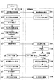
次に図10に基づいて、この測量システムでの測定手順について説明する。この測量システムをスタートさせると、ターゲット60は、ステップS1に進み、ガイド光送光器66からガイド光64を出射する。次に、ステップS2に進み、測量機50に測量機本体52を水平回転させる水平回転指令信号を送信する。すると、測量機50は、ステップS101で水平回転指令信号を受信し、次にステップS102に進んで水平回転開始通知をターゲット60に送信する。ターゲット60は、ステップS3で測量機本体52の水平回転を確認することにより、測量機50がガイド光64の水平方向サーチを開始したことを知る。
Next, based on FIG. 10, that describes the measurement procedure in this survey system. When you start to this survey system, the
一方、測量機50は、ステップS103に進み、測量機本体52を水平回転させ、さらにステップS104に進み、ガイド光64を受光してターゲット60の水平方向を検出する。ここで、ガイド光64を所定時間内に受光できないときは、ステップS105に進んで、エラー通知をターゲット60へ送信する。ターゲット60は、ステップS4でエラー通知を受け取ると、ステップS5に進んで、水平方向検出エラーを表示部84に表示して停止する。
On the other hand, the
ステップS104でガイド光64を受光したときは、ステップS106に進み、ガイド光送光器66に向けて望遠鏡54の水平方向位置を合わせて、測量機本体52の水平回転を停止させる。続いて、ステップS107に進み、ガイド光OFF指令をターゲット60に発信する。ターゲット60は、ステップS6でガイド光OFF指令を受けると、測量機50においてガイド光送光器66の水平方向サーチが完了したことが分かるので、ステップS7に進み、ガイド光64をOFFとし、続いてステップS8に進み、ガイド光OFF通知を測量機50に送信する。
When the
測量機50は、ステップS108でガイド光OFF通知を確認すると、ステップS109に進み、視準光58を出射し、続いてステップS110に進み、望遠鏡54の鉛直回転開始の通知をターゲット60に送信する。ターゲット60では、ステップS9で鉛直回転通知を確認することにより、測量機50がターゲット60の鉛直方向サーチを開始したことが分かる。一方、測量機では、ステップS111に進み、望遠鏡54を鉛直回転させ、ターゲット60の鉛直方向サーチを続ける。
When the
次に、測量機50は、ステップS112に進み、視準光58を出射するとともに、ターゲット60で反射して戻って来る視準光58を受光することにより、ターゲット60の鉛直方向を検出する。ここで、視準光58を受光できないときは、ステップS101に戻りフロー手順を繰り返すか、又はステップS113に進み、エラー通知をターゲット60に送信する。ターゲット60は、ステップS10でエラー通知を確認したときは、ステップS11に進み、鉛直方向検出エラーを表示部84に表示して停止する。
Next, the
ステップS112で視準光58を受光したときは、ステップS114に進み、ターゲット60の鉛直方向位置に望遠鏡54を合わせて、望遠鏡54を停止させる。続いてステップS115に進み、視準動作を開始し、視準中である旨の通知をターゲット60に通知する。ターゲット60は、ステップS12で視準中であることを確認することにより、測量機50において、自動視準装置が始動されたことを知る。一方、測量機50では、ステップS116に進み、自動視準動作を続行する。
When the
ステップS116で、うまく視準できないときは、ステップS117に進み、エラー通知をターゲット60に送信する。ターゲット60は、ステップS13でエラー通知を確認したときは、ステップS14に進み、視準エラーを表示部84に出力して停止する。ステップS116で、うまく視準できたときは、ステップS118に進み、視準完了通知をターゲット60に送信する。これで、ターゲット60は、ステップS15で、測量機50において自動視準が完了したことを知る。
If it is not possible to collimate well in step S116, the process proceeds to step S117, and an error notification is transmitted to the
そして、測量機50は、ステップS119に進み、測距・測角を行い、続いてステップS120に進み、測距値・測角値をターゲット60に通知する。ターゲット60は、ステップS16で、測距値・測角値を確認すると、表示部84に測距値・測角値等の測量結果等を表示して、測量を終了する。
Then, the surveying
なお、前述の各エラーによって、エラーを表示部84に表示して動作を停止した場合、エラーの原因を取り除いた後に、再度測量システムの動作をスタートさせればよい。
In addition, when the error is displayed on the
この測量システムによれば、ターゲット60側からファンビーム状のガイド光64をスキャンしながら出射するので、少ない電力で広い範囲に充分な強さのガイド光64を放射でき、測量機50は迅速にターゲット60を見付けて、自動視準を完了するまでの時間を短縮できる。
しかしながら、前記出願に開示された測量機50でも、測量機本体52を最初に回転させる方向を右回りか左回りかを適切に指示しないと、本来なら僅かな測量機本体52の回転でターゲット60を迅速に捕捉できるにもかかわらず、場合によっては360°近く測量機本体52を回転させて、やっとターゲット60を捕捉することもあり、自動視準に要する時間の短縮が不充分な場合もあるという問題があった。このような問題を解決するには、ターゲット60に回転方向を指示するボタンを付けて、作業員が測量機本体52の回転方向を指示すれば、簡単に解決できるが、これでは作業員の負担が増すという問題を生じてしまう。
However, even in the surveying
本発明は、前記問題に鑑みてなされたものであり、ターゲット側からガイド光を出射することによりターゲットを迅速に発見して自動視準に要する時間をできるだけ短縮した測量機において、作業員の負担を増すことなく、自動視準に要する時間をできるだけ短縮することを課題とする。 The present invention has been made in view of the above problems, and in a surveying instrument that quickly finds a target by emitting guide light from the target side and shortens the time required for automatic collimation as much as possible, the burden on the operator is reduced. It is an object to reduce the time required for automatic collimation as much as possible without increasing.
上記の課題を解決するため、請求項1に係る発明は、ターゲットと、該ターゲットを自動的に視準する自動視準装置を備えた測量機とからなる測量システムにおいて、前記ターゲットは、ガイド光を出射するガイド光送光器と、前記ターゲットの向いている方向角を検出する方位角センサと、前記測量機に回転指令を送る回転指令手段とを備え、前記測量機は、前記回転指令を受け取ると、前記ガイド光を受光して測量機本体を前記ターゲットに概略向ける回転手段を備え、前記回転指令手段又は前記回転手段は、前回の測定時に前記ターゲットを前記測量機に略正対させたときの方向角と、今回の測定時に前記ターゲットを前記測量機に略正対させたときの方向角との角度差が前記方位角センサの最大推定誤差角よりも大きなときは、前記角度差に基づいて決定された回転方向に前記測量機本体を回転させ、前記方向角の角度差が前記最大推定誤差角以下のときは、前記角度差よりも前記最大推定誤差角だけ大きな行き過ぎ角を決定し、前記測量機本体を前記行き過ぎ角まで回転させた後に逆転させることを特徴とする。 In order to solve the above-mentioned problem, the invention according to claim 1 is a surveying system comprising a target and a surveying instrument equipped with an automatic collimation device that automatically collimates the target. A guide light transmitter, an azimuth angle sensor for detecting a direction angle of the target, and a rotation command means for sending a rotation command to the surveying instrument, wherein the surveying instrument outputs the rotation command. When receiving, the light receiving device includes a rotating unit that receives the guide light and roughly orients the surveying instrument main body toward the target, and the rotation command unit or the rotating unit causes the target to face the surveying instrument at the time of the previous measurement. When the angle difference between the directional angle and the directional angle when the target is substantially directly opposed to the surveying instrument at the time of this measurement is larger than the maximum estimated error angle of the azimuth angle sensor, When the surveying instrument main body is rotated in the rotation direction determined based on the degree difference, and the angle difference between the direction angles is equal to or less than the maximum estimated error angle, an overshoot angle that is larger than the angle difference by the maximum estimated error angle The surveying instrument main body is rotated to the overshoot angle and then reversely rotated .
請求項2に係る発明は、ターゲットと、該ターゲットを自動的に視準する自動視準装置を備えた測量機とからなる測量システムにおいて、前記ターゲットは、ガイド光を出射するガイド光送光器と、前記ターゲットの向いている方向角を検出する方位角センサと、前記測量機に回転指令を送る回転指令手段とを備え、前記測量機は、前記回転指令を受け取ると、前記ガイド光を受光して測量機本体を前記ターゲットに概略向ける回転手段を備え、前記回転指令手段又は前記回転手段は、前回の測定時に前記ターゲットを前記測量機に略正対させたときの方向角と、今回の測定時に前記ターゲットを前記測量機に略正対させたときの方向角との角度差が前記方位角センサの最大推定誤差角とさらに誤差角に余裕を見込んだ安全誤差角との和よりも大きなときは、前記角度差に基づいて決定された回転方向に前記測量機本体を回転させ、前記方向角の角度差が前記最大推定誤差角より大きく前記最大推定誤差角と前記安全誤差角の和よりも小さなときは、前記角度差よりも前記最大推定誤差角と前記安全誤差角との和だけ大きな行き過ぎ角を決定して、前記測量機本体を前記行き過ぎ角まで回転させた後に逆転させ、前記方向角の角度差が前記最大推定誤差角よりも小さなときは、前記角度差よりも前記最大推定誤差角だけ大きな行き過ぎ角と、前記最大推定誤差角の2倍と前記安全誤差角との和に等しい戻り角を決定し、前記測量機本体を前記行き過ぎ角まで回転させた後に前記戻り角だけ逆転させ、前記戻り角だけ逆転させた後に、再び最初に決定した方向へ回転させることを特徴とする。 The invention according to claim 2 is a surveying system comprising a target and a surveying instrument equipped with an automatic collimation device for automatically collimating the target, wherein the target emits guide light. And an azimuth angle sensor for detecting a direction angle of the target and a rotation command means for sending a rotation command to the surveying instrument, and the surveying instrument receives the guide light when receiving the rotation command. Rotation means for roughly orienting the surveying instrument main body to the target, the rotation command means or the rotation means, the direction angle when the target is substantially directly opposed to the surveying instrument at the time of the previous measurement, than the sum of safe error angle that an allowance to the maximum estimated error angle further error angle of the angular difference is the azimuth sensor and the direction angle when almost were directly facing the target to the surveying instrument during measurement When the angle is large, the surveying instrument main body is rotated in the rotation direction determined based on the angle difference, and the angle difference between the direction angles is larger than the maximum estimated error angle, and the sum of the maximum estimated error angle and the safety error angle. Is smaller than the angle difference, determine the overshoot angle larger than the maximum estimated error angle and the safety error angle, rotate the surveying instrument main body to the overshoot angle, reverse the angle, When the angle difference between the direction angles is smaller than the maximum estimated error angle, the overshoot angle that is larger than the angle difference by the maximum estimated error angle, the double of the maximum estimated error angle, and the safety error angle An equal return angle is determined, the surveying instrument main body is rotated to the overshoot angle, the reverse angle is reversed, the reverse angle is reversed, and the surveying instrument main body is rotated again in the first determined direction. To.
請求項3に係る発明は、請求項1又は2に係る発明において、前記方位角センサが磁気センサであることを特徴とする。 The invention according to claim 3 is the invention according to claim 1 or 2 , wherein the azimuth angle sensor is a magnetic sensor.
請求項1に係る発明によれば、回転指令手段又は回転手段は、前回の測定時にターゲットを測量機に略正対させたときの方向角と、今回の測定時にターゲットを測量機に略正対させたときの方向角との角度差が方位角センサの最大推定誤差角よりも大きなときは、前記角度差に基づいて決定された回転方向に前記測量機本体を回転させ、前記方向角の角度差が前記最大推定誤差以下のときは、前記角度差よりも前記最大推定誤差だけ大きな行き過ぎ角を決定し、前記測量機本体を前記行き過ぎ角まで回転させた後に逆転させるから、前記角度差に応じてターゲットから出射されたガイド光を捕捉するために適切な回転パターンで測量機本体を回転させて、ターゲットから出射されたガイド光を捕捉することができ、作業員の負担を増すことなく、短時間で確実に自動視準をすることができ、作業効率を向上させることができる。 According to the invention of claim 1, rotation command means or the rotation means comprises a substantially regular and direction angle when substantially is directly facing the target to the surveying instrument at the time of the previous measurement, the target when this measurement to the surveying instrument When the angle difference with the direction angle when paired is larger than the maximum estimated error angle of the azimuth angle sensor, the surveying instrument main body is rotated in the rotation direction determined based on the angle difference, and the direction angle When the angle difference is less than or equal to the maximum estimation error, an overshoot angle that is larger than the angle difference by the maximum estimation error is determined, and the surveying instrument main body is rotated to the overshoot angle and then reversed. Correspondingly by rotating the instrument body in the proper rotation pattern to capture guide light emitted from the target, it is possible to capture the guide light emitted from the target, it can increase the burden on the operator , It is possible to reliably automatic collimation in a short time, thereby improving the working efficiency.
請求項2に係る発明によれば、さらに、前記回転指令手段又は前記回転手段は、前記方向角の角度差が前記方位角センサの最大推定誤差角とさらに誤差角に余裕を見込んだ安全誤差角との和よりも大きなときは、前記角度差に基づいて決定された回転方向に前記測量機本体を回転させ、前記方向角の角度差が前記最大推定誤差角より大きく前記最大推定誤差角と前記安全誤差角の和よりも小さなときは、前記角度差よりも前記最大推定誤差角と前記安全誤差角との和だけ大きな行き過ぎ角を決定して、前記測量機本体を前記行き過ぎ角まで回転させた後に逆転させ、前記方向角の角度差が前記最大推定誤差角よりも小さなときは、前記角度差よりも前記最大推定誤差角だけ大きな行き過ぎ角と、前記最大推定誤差角の2倍と前記安全誤差角との和に等しい戻り角を決定し、前記測量機本体を前記行き過ぎ角まで回転させた後に前記戻り角だけ逆転させ、前記戻り角だけ逆転させた後に、再び最初に決定した方向へ回転させるから、前記角度差に応じていっそう適切な回転パターンで測量機本体を回転させて、ターゲットから出射されたガイド光を捕捉することができ、いっそう短時間に確実に自動視準をすることができる。 According to the second aspect of the present invention, the rotation command means or the rotation means further includes a safety error angle in which an angle difference between the directional angles allows for a margin between the maximum estimated error angle of the azimuth angle sensor and the error angle. Is larger than the sum of the angle difference, the surveying instrument main body is rotated in the rotation direction determined based on the angle difference, and the angle difference between the direction angles is larger than the maximum estimated error angle and the maximum estimated error angle and the When the safety error angle is smaller than the sum of the safety error angles, an overshoot angle larger than the angle difference by the sum of the maximum estimated error angle and the safety error angle is determined, and the surveying instrument main body is rotated to the overshoot angle. When the angle difference between the directional angles is smaller than the maximum estimated error angle, an overshoot angle that is larger than the angle difference by the maximum estimated error angle, twice the maximum estimated error angle, and the safety error Horns and Determining a return angle equal to the sum, rotating the surveying instrument body to the overshoot angle, reversing the return angle, reversing the return angle, and then rotating again in the initially determined direction. The main body of the surveying instrument can be rotated with a more appropriate rotation pattern according to the angle difference, and the guide light emitted from the target can be captured, and automatic collimation can be performed more reliably in a shorter time.
請求項3に係る発明によれば、さらに、方位角センサは磁気センサであるから、安価で容易に本発明を実現できる。 According to the third aspect of the present invention, since the azimuth angle sensor is a magnetic sensor, the present invention can be easily realized at low cost.
以下、添付図面に基づいて、本発明の実施の形態を詳細に説明する。 Hereinafter, embodiments of the present invention will be described in detail with reference to the accompanying drawings.
まず、本発明を理解するための参考例に係る測量システムを図1〜図3に基づいて説明する。図1は、この測量システム全体のブロック図である。図2は、この測量システムの原理を説明する図である。図3は、この測量システムにおいて、測量機本体を略ターゲットの方向に位置合わせする手順を説明するフローチャートである。 First, a surveying system according to a reference example for understanding the present invention will be described with reference to FIGS. Figure 1 is a block diagram of the entire survey system. FIG. 2 is a diagram for explaining the principle of this surveying system . FIG. 3 is a flowchart for explaining a procedure for aligning the surveying instrument main body substantially in the direction of the target in this surveying system.
この測量システムは、図1に示されたように、ターゲット60に、ガイド光送光器66すなわちターゲット60の向きを測定する方位角センサ86と、この方位角センサ86で測定された方向角(方位角)を記憶する記憶部88とを備えている。この方位角センサ86と記憶部88とには演算制御部(CPU)80が接続されている。この演算制御部(CPU)80は、ターゲット60を移動させて距離や角度の測定する度に方位角センサ86で方向角を測定し、この方向角を記憶部88に記憶させ、そして、距離や角度の測定を開始すると、前回の測定時の方向角θAと今回の測定時の方向角θBとの角度差θB−θAを算出し、角度差θB−θAに応じて、測量機本体52の回転方向を決定して、この回転方向を含めた水平回転指令信号を無線65で測量機50へ送信する。
As shown in FIG. 1, the surveying system includes a
方位角センサ86としては、地磁気を検出することにより方向角を出力する磁気センサを用いる。方向角は、磁北を基準にして時計回りの角度で測定する。このような磁気センサの一例は、本出願人の出願による特開平9−329441号公報に開示されている。又は、ホール素子を用いた方位角センサでもよい。これ以外は、図6に示した従来の測量システムと同じ構成である。従って、この測量システムの構成については、これ以上の説明は省略する。
As the
図2に基づいて、本発明の原理を説明する。今、作業者が、A地点でターゲット60を測量機50に略正対させて距離や角度の測定をしたとき、制御演算部80は、方位角センサ86でガイド光送光器66が磁北方向Nとなす方向角θAを読んで、記憶部88に方向角θAを記憶させる。A地点での測定が終わって、ターゲット60をB地点に移動させると、再びターゲット60を測量機50に略正対させて測定を開始する。このとき、演算制御部80は、再び方位角センサ86でガイド光送光器66の方向角θBを読んで、前回のA地点での方向角θAと今回のB地点での方向角θBとの角度差Δθ=θB−θAを計算する。この角度差Δθはターゲット60から見た測量機50の方向角変化であるから、測量機本体52もこの角度差Δθだけ逆方向に回転させれば、測量機本体52はB地点のターゲット60に正対することになる。
The principle of the present invention will be described with reference to FIG. Now, when the operator measures the distance and angle with the
そこで、この角度差Δθ=θB−θAが、−180°≦Δθ<0°又は180°≦Δθ<360°のときは、ターゲットから測量機50へ反時計回り(左回り)の回転方向を含む回転指令信号を送信し、この角度差Δθ=θB−θAが、0°≦Δθ<180°又は−360°≦Δθ<−180°のときは、ターゲットから測量機50へ時計回り(右回り)の回転方向を含む回転指令信号を送信して、測量機本体52を指定された向きに回転させる。これで、測量機本体52に対して、適切な回転方向を作業員の負担無しに自動的に決定でき、常に180°以内の最小の回転角で、ガイド光66を捕捉できるので、作業効率を向上させることができる。
Therefore, when the angle difference Δθ = θB−θA is −180 ° ≦ Δθ <0 ° or 180 ° ≦ Δθ <360 °, the rotation direction from the target to the surveying
なお、角度差Δθが±0°付近の場合は測量機本体が回転しなくてもガイド光66を捕捉でき、Δθが±180°付近の場合は、右回りでも左回りでもガイド光66を捕捉するまでの時間はほとんど同じになるから、方位角センサ86はさほど高精度でなくてもよく、また、測定時にターゲット60を測量機50に正確に正対させる必要はなく略正対させる程度でもよい。
When the angle difference Δθ is around ± 0 °, the
次に、この測量システムの測定手順について、図3のフローチャートに基づいて説明する。 Next, the measurement procedure of this surveying system will be described based on the flowchart of FIG.
この測量システムをスタートさせると、ターゲット60は、ステップS21に進み、測定開始指令を測量機50へ送信する。測量機50は、測定開始指令を受け取るとステップS91に進み、ガイド光ON指令をターゲット60に送信する。ターゲット60は、ステップS22でガイド光ON指令を受信するとステップS23に進んで、ガイド光送光器66からガイド光64を出力する。次に、ターゲット60は、ステップS24に進み、方位角センサ86から方向角θBを取得し記憶部88に記憶する。次に、ターゲット60は、ステップS25に進み、今回の測定時に取得した方向角θBと前回の測定時に取得した方向角θAの角度差を算出して、続いてステップS26に進み、測量機50に指示する回転方向を決定し、さらに、ステップS27に進んで、回転方向を含む水平回転指令を測量機50に送信する。
When the surveying system is started, the
測量機50は、ステップS93で水平回転指令を受信すると、ステップS103に進んで測量機本体52を水平回転し、さらにステップS104に進んで、ガイド光64を検出することにより、ターゲット60の水平方向検出を行う。ここで、ガイド光64を所定時間内に受光できないときは、ステップS105に進み、エラー通知をターゲット60に送信する。ターゲット60は、ステップS4でエラ−通知を確認すると、ステップS5に進み、水平検出エラーを表示部84に表示して、動作を停止する。ステップS104でガイド光64を受光したときは、ターゲット60の水平方向を検出したと判断し、ステップS106に進み、ガイド光送光器66に向けて望遠鏡54の水平方向位置を合わせて、測量機本体52の水平回転を停止させる。これ以後の手順は、図10に示した従来のものと同じであるから説明を省略する。水平検出エラーを表示部84に表示して動作を停止した場合、エラーの原因を取り除いた後に、再度測量システムの動作をスタートさせればよい。
When receiving the horizontal rotation command in step S93, the surveying
この測量システムによれば、ガイド光64は、水平方向に幅広で上下幅の狭いファンビームであるから、遠方まで到達させることができ、しかも、鉛直方向に走査されて、上下左右の広い範囲を照射するので、測量機50とターゲット60とに大きな高低差があっても、測量機50とターゲット60とが正対していなくても、測量機50に設けられた方向検出器56は、確実にガイド光64を受光して、自動視準開始前に予め望遠鏡54をほぼターゲット60の方向に向ける視準準備を確実に行うことができる。しかも、ターゲット60からは、ガイド光64の送光とともに、測量機50へ適切な回転方向が自動的に指示され、測量機本体52は常に180°以内の最小の水平回転でガイド光64を受光できる。このように、測量機本体52の適切な回転方向を自動的に決定して測量機50に指示するので、作業員の負担無く、作業効率を向上させることができる。
According to this surveying system , the
次に、本発明の第1実施例に係る測量システムについて説明する。この測量システムは、図1に示した参考施例と同じく構成されているが、測量機本体52をターゲット60の方向へ位置合わせする手順が相違する。この手順を以下に図4及び図5に基づいて説明する。
Next , the survey system according to the first embodiment of the present invention will be described. This surveying system is configured in the same manner as the reference example shown in FIG. 1, but the procedure for aligning the surveying instrument
図4に示したように、この測量システムをスタートさせてから、ターゲット60がステップS25に進み、今回取得した方向角θBと前回取得した方向角θAの角度差Δθ=θB−θAを算出するまでは、前記参考例と同じである。
As shown in FIG. 4, after this surveying system is started, the
続いて、ステップS30に進み、今回取得した方向角θBと前回取得した方向角θAの角度差Δθと方位角センサ86の最大推定誤差Eとの大小を比較する。最大推定誤差Eは、方位角センサ86に磁気センサを使用している場合、近くに磁性体からなる構造物等がある場合を考慮し、最大30°程度と推定する。この他に、作業者がターゲット60を測量機50に正対させる際にも、最大5°程度の誤差が発生する可能性がある。このため、通常は、最大推定誤差Eを35°程度と推定する。したがって、図5に示したように、測定点Aから測定点Bまでターゲット60を移動させたときに、両点A、Bでの方向角の角度差をΔθとすると、Δθ±EすなわちΔθ±35°の範囲でガイド光64をサーチするように測量機本体52を回転させれば、ガイド光64を確実に検出できることになる。もちろん、外部環境等によっては、最大推定誤差Eを適当に増減してもよい。
Subsequently, the process proceeds to step S30, and the magnitude of the angle difference Δθ between the direction angle θB acquired this time and the direction angle θA acquired last time and the maximum estimation error E of the
ステップS30において、Δθ>Eであれば、ステップS31に進んで、図5の(A)に示したように、前記第1の実施例と同様に、測量機本体52の回転方向を決定するとともに、測量機本体52を指示された回転方向に単純に回転させる回転パターンP1の回転指令が作成される。この回転パターンP1で、Δθの誤差範囲のΔθ±Eを早期に確実にカバーできる。
If Δθ> E in step S30, the process proceeds to step S31, and as shown in FIG. 5A, the rotation direction of the surveying instrument
ステップS30において、Δθ≦Eであれば、ステップS32に進んで、図5の(B)に示したように、測量機本体52の回転方向を決定するとともに、角度差Δθよりも最大推定誤差Eだけ大きな行き過ぎ角θ1=Δθ+Eを決定し、測量機本体52を行き過ぎ角θ1まで回転させた後に戻り角θ2まで逆転させ、そのまま同一方向に回転を続行させる折り返し形の回転パターンP2の回転指令が作成される。この回転パターンP2で、Δθの誤差範囲のΔθ±Eを早期に確実にカバーできる。特に、Δθの誤差のため、回転方向を誤ってしまった場合でも、測量機本体52を最小の回転角でガイド光64を迅速確実に捕捉できる。
If Δθ ≦ E in step S30, the process proceeds to step S32, where the rotation direction of the surveying instrument
こうして回転指令が作成されると、ステップS27に進んで、ターゲット60から測量機50に回転指令が送られる。測量機50は、ここで、制御演算部80によって実行されるステップS24、S25、S30〜S32、S27が、本発明の回転指令手段に相当する。
When the rotation command is created in this way, the process proceeds to step S27, and the rotation command is sent from the
測量機50は、ステップS93で水平回転指令を受信すると、ステップS103に進んで測量機本体52を水平回転させ、さらにステップS104に進んで、ガイド光64の検出することにより、ターゲット60の水平方向検出を行う。これ以後の手順は、図3に示した参考例と同じであるから説明を省略する。なお、制御演算部100によって実行されるステップS93〜S106、方向検出器56、水平駆動部104及び水平モータ102が、本発明の回転手段に相当する。
When the surveying
本実施例によれば、角度差Δθが方位角センサ86の最大推定誤差角Eよりも大きなときは回転パターンP1を、角度差Δθが最大推定誤差E以下のときは折り返し形回転パターンP2を選択し、角度差Δθに応じて適切な回転パターンで測量機本体52を回転させて、ターゲット60から出射されたガイド光64を早期に確実に捕捉するので、作業員の負担を増すことなく、測量機本体52の適切な回転方向を自動的に決定して測量機50に指示して、作業効率を向上させることができる。
According to this embodiment, when the angle difference Δθ is larger than the maximum estimated error angle E of the
次に、本発明の第2実施例に係る測量システムについて、図6及び図7に基づいて説明する。この測量システムは、前記第1の実施例を、さらに改良したものあり、図6に示したように、移動後のターゲット60の存在する最大誤差範囲として、通常予想される最大推定誤差角Eの外側に、さらにターゲット60捕捉の確実性を増すために誤差角に余裕を見込んだ安全誤差角E’を設定している。安全誤差角E’は、通常30°程度とする。もちろん、外部環境等によっては、安全誤差角E’を適当に増減してもよい。
Next , a surveying system according to a second embodiment of the present invention will be described with reference to FIGS. This surveying system is a further improvement of the first embodiment. As shown in FIG. 6, as the maximum error range in which the
図7のフローチャートにおいて、ステップS25で、今回取得した方向角θBと前回取得した方向角θAの角度差Δθを求めるまでは、図4に示した第1実施例と同じである。本実施例では、次にステップS40に進んで、角度差Δθと最大推定誤差角Eと安全誤差角E’の比較を行う。 In the flowchart of FIG. 7, the process is the same as that of the first embodiment shown in FIG. 4 until the angle difference Δθ between the direction angle θB acquired this time and the direction angle θA acquired last time is obtained in step S25. In this embodiment, the process then proceeds to step S40, where the angle difference Δθ, the maximum estimated error angle E, and the safety error angle E ′ are compared.
今回取得した方向角θBと前回取得した方向角θAの角度差Δθと最大推定誤差角Eと安全誤差角E’の間で、E+E’<Δθのときは、ステップS41へ進んで、前記第1の実施例と同様に、測量機本体52の回転方向を決定するとともに、測量機本体52を指示された回転方向に単純に回転させる回転パターンP1の回転指令が作成される(図6の(A)参照)。
If E + E ′ <Δθ between the angle difference Δθ between the direction angle θB acquired this time and the direction angle θA acquired last time, the maximum estimated error angle E, and the safety error angle E ′, the process proceeds to step S41, and the first In the same manner as in the embodiment, the rotation direction of the surveying instrument
E<Δθ≦E+E’のときは、ステップS42へ進んで、行き過ぎ角θ1を、θ1=Δθ+E+E’と決定して、測量機本体52を行き過ぎ角θ1まで回転させた後に、逆転を続行させる折り返し形の回転パターンP2の回転指令が作成される(図6の(B)参照)。
When E <Δθ ≦ E + E ′, the process proceeds to step S42, the overshoot angle θ1 is determined as θ1 = Δθ + E + E ′, the surveying instrument
Δθ≦Eのときは、ステップS43へ進んで、行き過ぎ角θ1を、θ1=Δθ+Eと決定するとともに、戻り角θ2を、θ2=E+E+E’と決定して、測量機本体52を行き過ぎ角θ1まで回転させた後に、戻り角θ2だけ逆転させ、その後、最初の回転方向へ回転させる折り返し形の回転パターンP3の回転指令が作成される(図6の(C)参照)。
When Δθ ≦ E, the process proceeds to step S43, the overshoot angle θ1 is determined as θ1 = Δθ + E, the return angle θ2 is determined as θ2 = E + E + E ′, and the surveying instrument
こうして回転パターンP1、P2、P3が決定された後は、ステップS27へ進み、この後は、図4に示した第1実施例と同じである。 After the rotation patterns P1, P2, and P3 are determined in this way, the process proceeds to step S27, and thereafter, the same as in the first embodiment shown in FIG.
本実施例の場合は、Δθの誤差範囲Δθ±E±E’を早期に確実にカバーして、ターゲット60の補足ミスを少なくするので、前記第1実施例に比べて、さらに作業効率を向上させることができる。
In the case of this embodiment, the error range Δθ ± E ± E ′ of Δθ is surely covered at an early stage, and the number of supplemental errors of the
ところで、本発明は、前記実施例に限るものではなく、例えば次のように種々の変形が可能である。 By the way, the present invention is not limited to the above-described embodiments, and various modifications are possible as follows, for example.
前記両実施例では、ターゲット60側の回転指令手段の制御演算部80で回転方向を決定したが、ターゲット60側からは測定した方向角θA、θBを測量機50側へ送って、測量機50側の回転手段の制御演算部100で回転方向を決定するようにしてもよい。この場合でも、前記両実施例と同じ効果を奏する。また、前記両実施例では、方位角センサ86として安価な磁気センサを用いたが、方位角センサ86としては、放送局等位置の定まっている電波原からの電波の到来方向を検出する無線方位測定機、常に一定姿勢を維持するジャイロ等、方向角を検出できるものであれば皆使用可能である。
In both the above embodiments, the rotation direction is determined by the
前記両実施例ではステップS24(図3及び図5参照)で方向角の取得と記録を行ったが、この方向角の取得と記録は、スタートした後からステップS25までの間のどこで行ってもよい。 In both the above embodiments, the direction angle is acquired and recorded in step S24 (see FIGS. 3 and 5). However, the acquisition and recording of the direction angle is performed anywhere from the start to step S25. Good.
前記両実施例ではターゲット60からファンビーム状のガイド光64を走査しながら出射したが、単純な拡散光のガイド光64を出射してもよい。
In both of the above embodiments, the fan beam-shaped
50 測量機
52 測量機本体
60 ターゲット
64 ガイド光
66 ガイド光送光器
80 制御演算部(回転指令手段)
86 方位角センサ
100 制御演算部(回転手段)
Δθ 今回の測定時と前回の測定時に取得した方向角の角度差
θ1 行き過ぎ角
θ2 戻り角
E 最大推定誤差角
E’ 安全誤差角
DESCRIPTION OF
86
Δθ Difference in angle between the current and previous measurements θ1 Overshoot angle θ2 Return angle E Maximum estimated error angle E 'Safety error angle
Claims (3)
前記ターゲットは、ガイド光を出射するガイド光送光器と、前記ターゲットの向いている方向角を検出する方位角センサと、前記測量機に回転指令を送る回転指令手段とを備え、
前記測量機は、前記回転指令を受け取ると、前記ガイド光を受光して測量機本体を前記ターゲットに概略向ける回転手段を備え、
前記回転指令手段又は前記回転手段は、前回の測定時に前記ターゲットを前記測量機に略正対させたときの方向角と、今回の測定時に前記ターゲットを前記測量機に略正対させたときの方向角との角度差が前記方位角センサの最大推定誤差角よりも大きなときは、前記角度差に基づいて決定された回転方向に前記測量機本体を回転させ、
前記方向角の角度差が前記最大推定誤差角以下のときは、前記角度差よりも前記最大推定誤差角だけ大きな行き過ぎ角を決定し、前記測量機本体を前記行き過ぎ角まで回転させた後に逆転させることを特徴とする測量システム。 In a survey system comprising a target and a surveying instrument equipped with an automatic collimation device for automatically collimating the target,
The target includes a guide light transmitter that emits guide light, an azimuth angle sensor that detects a direction angle of the target, and a rotation command unit that sends a rotation command to the surveying instrument.
When the surveying instrument receives the rotation command, the surveying instrument includes a rotating unit that receives the guide light and roughly directs the surveying instrument main body toward the target,
The rotation command means or the rotation means is a direction angle when the target is substantially directly opposed to the surveying instrument at the previous measurement, and when the target is approximately directly opposed to the surveying instrument at the current measurement. When the angle difference with the direction angle is larger than the maximum estimated error angle of the azimuth angle sensor, rotate the surveying instrument body in the rotation direction determined based on the angle difference,
When the angle difference between the direction angles is equal to or less than the maximum estimated error angle, an overshoot angle larger than the angle difference by the maximum estimated error angle is determined, and the surveying instrument main body is rotated to the overshoot angle and then reversed. Surveying system characterized by that.
前記ターゲットは、ガイド光を出射するガイド光送光器と、前記ターゲットの向いている方向角を検出する方位角センサと、前記測量機に回転指令を送る回転指令手段とを備え、 The target includes a guide light transmitter that emits guide light, an azimuth angle sensor that detects a direction angle of the target, and a rotation command unit that sends a rotation command to the surveying instrument.
前記測量機は、前記回転指令を受け取ると、前記ガイド光を受光して測量機本体を前記ターゲットに概略向ける回転手段を備え、 When the surveying instrument receives the rotation command, the surveying instrument includes a rotating unit that receives the guide light and roughly directs the surveying instrument main body toward the target,
前記回転指令手段又は前記回転手段は、前回の測定時に前記ターゲットを前記測量機に略正対させたときの方向角と、今回の測定時に前記ターゲットを前記測量機に略正対させたときの方向角との角度差が前記方位角センサの最大推定誤差角とさらに誤差角に余裕を見込んだ安全誤差角との和よりも大きなときは、前記角度差に基づいて決定された回転方向に前記測量機本体を回転させ、 The rotation command means or the rotation means is a direction angle when the target is substantially directly opposed to the surveying instrument at the previous measurement, and when the target is approximately directly opposed to the surveying instrument at the current measurement. When the angle difference with the direction angle is larger than the sum of the maximum estimated error angle of the azimuth angle sensor and a safety error angle with a margin for the error angle, the rotational direction determined based on the angle difference Rotate the surveying instrument body,
前記方向角の角度差が前記最大推定誤差角より大きく前記最大推定誤差角と前記安全誤差角の和よりも小さなときは、前記角度差よりも前記最大推定誤差角と前記安全誤差角との和だけ大きな行き過ぎ角を決定して、前記測量機本体を前記行き過ぎ角まで回転させた後に逆転させ、 When the angle difference between the direction angles is larger than the maximum estimated error angle and smaller than the sum of the maximum estimated error angle and the safety error angle, the sum of the maximum estimated error angle and the safety error angle is larger than the angle difference. Determine the overshoot angle as large as possible, rotate the surveying instrument body to the overshoot angle and reverse it,
前記方向角の角度差が前記最大推定誤差角よりも小さなときは、前記角度差よりも前記最大推定誤差角だけ大きな行き過ぎ角と、前記最大推定誤差角の2倍と前記安全誤差角との和に等しい戻り角を決定し、前記測量機本体を前記行き過ぎ角まで回転させた後に前記戻り角だけ逆転させ、前記戻り角だけ逆転させた後に、再び最初に決定した方向へ回転させることを特徴とする測量システム。 When the angle difference between the direction angles is smaller than the maximum estimated error angle, an overshoot angle larger than the angle difference by the maximum estimated error angle, a sum of twice the maximum estimated error angle and the safety error angle And returning the surveying instrument body to the overshoot angle, reversing it by the return angle, reversing the return angle, and then rotating it again in the first determined direction. Surveying system to do.
Priority Applications (4)
| Application Number | Priority Date | Filing Date | Title |
|---|---|---|---|
| JP2005033639A JP4648025B2 (en) | 2005-02-09 | 2005-02-09 | Surveying system |
| DE102006003865.7A DE102006003865B4 (en) | 2005-02-09 | 2006-01-27 | monitoring system |
| US11/348,325 US7304729B2 (en) | 2005-02-09 | 2006-02-07 | Survey system |
| CN200610006498A CN100588904C (en) | 2005-02-09 | 2006-02-09 | Measuring system |
Applications Claiming Priority (1)
| Application Number | Priority Date | Filing Date | Title |
|---|---|---|---|
| JP2005033639A JP4648025B2 (en) | 2005-02-09 | 2005-02-09 | Surveying system |
Publications (2)
| Publication Number | Publication Date |
|---|---|
| JP2006220514A JP2006220514A (en) | 2006-08-24 |
| JP4648025B2 true JP4648025B2 (en) | 2011-03-09 |
Family
ID=36709911
Family Applications (1)
| Application Number | Title | Priority Date | Filing Date |
|---|---|---|---|
| JP2005033639A Active JP4648025B2 (en) | 2005-02-09 | 2005-02-09 | Surveying system |
Country Status (4)
| Country | Link |
|---|---|
| US (1) | US7304729B2 (en) |
| JP (1) | JP4648025B2 (en) |
| CN (1) | CN100588904C (en) |
| DE (1) | DE102006003865B4 (en) |
Cited By (1)
| Publication number | Priority date | Publication date | Assignee | Title |
|---|---|---|---|---|
| EP3971521A1 (en) | 2020-09-18 | 2022-03-23 | Topcon Corporation | Target direction determining device, control system, and method and program for aiming surveying device at a target |
Families Citing this family (35)
| Publication number | Priority date | Publication date | Assignee | Title |
|---|---|---|---|---|
| CN101680759B (en) * | 2007-05-30 | 2012-03-21 | 特林布尔公司 | Target for use in measuring and surveying applications |
| JP5124321B2 (en) * | 2008-03-21 | 2013-01-23 | 株式会社トプコン | Measuring system |
| US9482755B2 (en) | 2008-11-17 | 2016-11-01 | Faro Technologies, Inc. | Measurement system having air temperature compensation between a target and a laser tracker |
| US8422034B2 (en) | 2010-04-21 | 2013-04-16 | Faro Technologies, Inc. | Method and apparatus for using gestures to control a laser tracker |
| US9377885B2 (en) | 2010-04-21 | 2016-06-28 | Faro Technologies, Inc. | Method and apparatus for locking onto a retroreflector with a laser tracker |
| US9400170B2 (en) | 2010-04-21 | 2016-07-26 | Faro Technologies, Inc. | Automatic measurement of dimensional data within an acceptance region by a laser tracker |
| US8619265B2 (en) | 2011-03-14 | 2013-12-31 | Faro Technologies, Inc. | Automatic measurement of dimensional data with a laser tracker |
| US8537371B2 (en) | 2010-04-21 | 2013-09-17 | Faro Technologies, Inc. | Method and apparatus for using gestures to control a laser tracker |
| US9772394B2 (en) | 2010-04-21 | 2017-09-26 | Faro Technologies, Inc. | Method and apparatus for following an operator and locking onto a retroreflector with a laser tracker |
| US8724119B2 (en) | 2010-04-21 | 2014-05-13 | Faro Technologies, Inc. | Method for using a handheld appliance to select, lock onto, and track a retroreflector with a laser tracker |
| JP5623227B2 (en) * | 2010-09-30 | 2014-11-12 | 株式会社トプコン | Measuring method and measuring device |
| US8684632B2 (en) | 2010-12-08 | 2014-04-01 | Laserline Mfg., Inc. | Systems and methods for laying out and installing a solar panel array |
| GB2518769A (en) | 2011-03-03 | 2015-04-01 | Faro Tech Inc | Target apparatus and method |
| US9686532B2 (en) | 2011-04-15 | 2017-06-20 | Faro Technologies, Inc. | System and method of acquiring three-dimensional coordinates using multiple coordinate measurement devices |
| US9482529B2 (en) | 2011-04-15 | 2016-11-01 | Faro Technologies, Inc. | Three-dimensional coordinate scanner and method of operation |
| US9164173B2 (en) | 2011-04-15 | 2015-10-20 | Faro Technologies, Inc. | Laser tracker that uses a fiber-optic coupler and an achromatic launch to align and collimate two wavelengths of light |
| WO2012141868A1 (en) | 2011-04-15 | 2012-10-18 | Faro Technologies, Inc. | Enhanced position detector in laser tracker |
| CN102269585B (en) * | 2011-04-29 | 2012-11-07 | 西南交通大学 | Method for precisely measuring survey beacon height |
| US9222771B2 (en) | 2011-10-17 | 2015-12-29 | Kla-Tencor Corp. | Acquisition of information for a construction site |
| CN103166549B (en) * | 2011-12-16 | 2015-09-30 | 株式会社电装 | Angle detector |
| CN104094081A (en) | 2012-01-27 | 2014-10-08 | 法罗技术股份有限公司 | Inspection method with barcode identification |
| CN103148843B (en) * | 2013-02-07 | 2015-05-20 | 上海岩土工程勘察设计研究院有限公司 | Observation method for deformation observation instrument |
| US9041914B2 (en) | 2013-03-15 | 2015-05-26 | Faro Technologies, Inc. | Three-dimensional coordinate scanner and method of operation |
| US9234742B2 (en) | 2013-05-01 | 2016-01-12 | Faro Technologies, Inc. | Method and apparatus for using gestures to control a laser tracker |
| US8848180B1 (en) | 2013-09-05 | 2014-09-30 | Laserline Mfg., Inc. | Reference systems for indicating slope and alignment and related devices, systems, and methods |
| JP6211876B2 (en) | 2013-10-01 | 2017-10-11 | 株式会社トプコン | Measuring method and measuring device |
| US9797719B2 (en) | 2013-10-01 | 2017-10-24 | Kabushiki Kaisha Topcon | Measuring method and measuring instrument |
| JP6333075B2 (en) * | 2014-06-04 | 2018-05-30 | 株式会社トプコン | Surveying equipment |
| US9395174B2 (en) | 2014-06-27 | 2016-07-19 | Faro Technologies, Inc. | Determining retroreflector orientation by optimizing spatial fit |
| WO2016073208A1 (en) | 2014-11-03 | 2016-05-12 | Faro Technologies, Inc. | Method and apparatus for locking onto a retroreflector with a laser tracker |
| CN104807433B (en) * | 2015-03-25 | 2017-03-01 | 杭州电子科技大学 | Spherical spinner space two-dimensional angle detection method based on optical autocollimating principle |
| WO2017151196A1 (en) | 2016-02-29 | 2017-09-08 | Faro Technologies, Inc. | Laser tracker system |
| JP6963936B2 (en) * | 2017-08-25 | 2021-11-10 | 株式会社トプコン | Surveying system |
| JP6899737B2 (en) | 2017-08-28 | 2021-07-07 | 株式会社トプコン | Surveying system |
| JP7464558B2 (en) | 2021-03-29 | 2024-04-09 | 株式会社トプコン | Survey data processing device, survey data processing method, and survey data processing program |
Citations (6)
| Publication number | Priority date | Publication date | Assignee | Title |
|---|---|---|---|---|
| JPS63225120A (en) * | 1987-03-14 | 1988-09-20 | Kozo Yamamoto | One-man surveying system |
| JPS63281012A (en) * | 1987-05-13 | 1988-11-17 | Tokyo Optical Co Ltd | Surveying device |
| JPH09329441A (en) * | 1996-06-12 | 1997-12-22 | Sokkia Co Ltd | Range finder |
| JP2000221032A (en) * | 1999-02-02 | 2000-08-11 | Sokkia Co Ltd | Surveying system |
| JP2001013247A (en) * | 1999-07-01 | 2001-01-19 | Nikon Corp | Automatic survey system |
| JP2001033251A (en) * | 1999-07-23 | 2001-02-09 | Sgs:Kk | Opening and closing device for reflection prism, and surveying by total station using opening and closing device for reflection prism |
Family Cites Families (8)
| Publication number | Priority date | Publication date | Assignee | Title |
|---|---|---|---|---|
| DE2445635A1 (en) * | 1974-09-25 | 1976-04-15 | Bayer Ag | Indicating device for load application - has laser light source directed at separate pentagonal prism |
| JP3075384B2 (en) | 1993-09-16 | 2000-08-14 | 株式会社トプコン | Surveying equipment |
| JP4320099B2 (en) * | 1999-03-26 | 2009-08-26 | 株式会社トプコン | Surveying equipment |
| JP2003273471A (en) | 2002-03-18 | 2003-09-26 | Kansai Tlo Kk | Semiconductor laser |
| JP2004144899A (en) * | 2002-10-23 | 2004-05-20 | Sharp Corp | Image forming method by electrophotography, electrophotographic toner, and method for manufacturing toner |
| JP2004144629A (en) * | 2002-10-25 | 2004-05-20 | Pentax Precision Co Ltd | Surveying equipment |
| JP2004212283A (en) * | 2003-01-07 | 2004-07-29 | Nikon-Trimble Co Ltd | Surveying airplane, target for surveying airplane, and automatic collimation surveying system |
| JP4177784B2 (en) * | 2004-05-14 | 2008-11-05 | 株式会社 ソキア・トプコン | Surveying system |
-
2005
- 2005-02-09 JP JP2005033639A patent/JP4648025B2/en active Active
-
2006
- 2006-01-27 DE DE102006003865.7A patent/DE102006003865B4/en active Active
- 2006-02-07 US US11/348,325 patent/US7304729B2/en active Active
- 2006-02-09 CN CN200610006498A patent/CN100588904C/en active Active
Patent Citations (6)
| Publication number | Priority date | Publication date | Assignee | Title |
|---|---|---|---|---|
| JPS63225120A (en) * | 1987-03-14 | 1988-09-20 | Kozo Yamamoto | One-man surveying system |
| JPS63281012A (en) * | 1987-05-13 | 1988-11-17 | Tokyo Optical Co Ltd | Surveying device |
| JPH09329441A (en) * | 1996-06-12 | 1997-12-22 | Sokkia Co Ltd | Range finder |
| JP2000221032A (en) * | 1999-02-02 | 2000-08-11 | Sokkia Co Ltd | Surveying system |
| JP2001013247A (en) * | 1999-07-01 | 2001-01-19 | Nikon Corp | Automatic survey system |
| JP2001033251A (en) * | 1999-07-23 | 2001-02-09 | Sgs:Kk | Opening and closing device for reflection prism, and surveying by total station using opening and closing device for reflection prism |
Cited By (2)
| Publication number | Priority date | Publication date | Assignee | Title |
|---|---|---|---|---|
| EP3971521A1 (en) | 2020-09-18 | 2022-03-23 | Topcon Corporation | Target direction determining device, control system, and method and program for aiming surveying device at a target |
| US11933611B2 (en) | 2020-09-18 | 2024-03-19 | Topcon Corporation | Target direction determining device, control system, and method and program for aiming surveying device at a target |
Also Published As
| Publication number | Publication date |
|---|---|
| JP2006220514A (en) | 2006-08-24 |
| US7304729B2 (en) | 2007-12-04 |
| US20060176473A1 (en) | 2006-08-10 |
| CN100588904C (en) | 2010-02-10 |
| DE102006003865B4 (en) | 2016-06-16 |
| DE102006003865A1 (en) | 2006-08-10 |
| CN1818551A (en) | 2006-08-16 |
Similar Documents
| Publication | Publication Date | Title |
|---|---|---|
| JP4648025B2 (en) | Surveying system | |
| JP4177765B2 (en) | Surveying system | |
| JP4177784B2 (en) | Surveying system | |
| US7321420B2 (en) | Survey system | |
| US10895632B2 (en) | Surveying system | |
| EP3677872B1 (en) | Surveying instrument | |
| US7742176B2 (en) | Method and system for determining the spatial position of a hand-held measuring appliance | |
| JP6630515B2 (en) | Position guidance device, position guidance method, program | |
| EP3136049B1 (en) | Total station | |
| CA2867562A1 (en) | Three-dimensional measuring method and surveying system | |
| JP6130078B2 (en) | Surveying information marking device, surveying information marking method | |
| KR100892147B1 (en) | Gis system | |
| US11500096B2 (en) | Surveying instrument | |
| US10591290B2 (en) | Survey system | |
| US20190129007A1 (en) | Reflecting prism, measurement target object including reflecting prism, surveying device, coordinate comparing section, surveying method, and surveying processing program | |
| JP2012122920A (en) | Survey system | |
| JP2019113507A (en) | Measurement apparatus, measurement control device, measurement control method and measurement control processing program | |
| JP2013152224A (en) | Optical system | |
| EP3812795B1 (en) | Scanner system and scan method | |
| US9932719B2 (en) | Control system for construction machine | |
| JP7289252B2 (en) | Scanner system and scanning method | |
| WO2024071287A1 (en) | Twist ring polygon mirror, light transmitter, and surveying system | |
| CN115494474A (en) | Measuring device, optical axis conversion unit, measuring method, and storage medium |
Legal Events
| Date | Code | Title | Description |
|---|---|---|---|
| A621 | Written request for application examination |
Free format text: JAPANESE INTERMEDIATE CODE: A621 Effective date: 20071206 |
|
| A977 | Report on retrieval |
Free format text: JAPANESE INTERMEDIATE CODE: A971007 Effective date: 20100617 |
|
| A131 | Notification of reasons for refusal |
Free format text: JAPANESE INTERMEDIATE CODE: A131 Effective date: 20100622 |
|
| A521 | Request for written amendment filed |
Free format text: JAPANESE INTERMEDIATE CODE: A523 Effective date: 20100818 |
|
| TRDD | Decision of grant or rejection written | ||
| A01 | Written decision to grant a patent or to grant a registration (utility model) |
Free format text: JAPANESE INTERMEDIATE CODE: A01 Effective date: 20101207 |
|
| A01 | Written decision to grant a patent or to grant a registration (utility model) |
Free format text: JAPANESE INTERMEDIATE CODE: A01 |
|
| A61 | First payment of annual fees (during grant procedure) |
Free format text: JAPANESE INTERMEDIATE CODE: A61 Effective date: 20101209 |
|
| FPAY | Renewal fee payment (event date is renewal date of database) |
Free format text: PAYMENT UNTIL: 20131217 Year of fee payment: 3 |
|
| R150 | Certificate of patent or registration of utility model |
Ref document number: 4648025 Country of ref document: JP Free format text: JAPANESE INTERMEDIATE CODE: R150 Free format text: JAPANESE INTERMEDIATE CODE: R150 |
|
| FPAY | Renewal fee payment (event date is renewal date of database) |
Free format text: PAYMENT UNTIL: 20131217 Year of fee payment: 3 |
|
| S531 | Written request for registration of change of domicile |
Free format text: JAPANESE INTERMEDIATE CODE: R313531 |
|
| FPAY | Renewal fee payment (event date is renewal date of database) |
Free format text: PAYMENT UNTIL: 20131217 Year of fee payment: 3 |
|
| R350 | Written notification of registration of transfer |
Free format text: JAPANESE INTERMEDIATE CODE: R350 |
|
| FPAY | Renewal fee payment (event date is renewal date of database) |
Free format text: PAYMENT UNTIL: 20131217 Year of fee payment: 3 |
|
| R250 | Receipt of annual fees |
Free format text: JAPANESE INTERMEDIATE CODE: R250 |
|
| R250 | Receipt of annual fees |
Free format text: JAPANESE INTERMEDIATE CODE: R250 |
|
| R250 | Receipt of annual fees |
Free format text: JAPANESE INTERMEDIATE CODE: R250 |
|
| R250 | Receipt of annual fees |
Free format text: JAPANESE INTERMEDIATE CODE: R250 |
|
| R250 | Receipt of annual fees |
Free format text: JAPANESE INTERMEDIATE CODE: R250 |
|
| R250 | Receipt of annual fees |
Free format text: JAPANESE INTERMEDIATE CODE: R250 |
|
| S111 | Request for change of ownership or part of ownership |
Free format text: JAPANESE INTERMEDIATE CODE: R313113 |
|
| R360 | Written notification for declining of transfer of rights |
Free format text: JAPANESE INTERMEDIATE CODE: R360 |
|
| R360 | Written notification for declining of transfer of rights |
Free format text: JAPANESE INTERMEDIATE CODE: R360 |
|
| R371 | Transfer withdrawn |
Free format text: JAPANESE INTERMEDIATE CODE: R371 |
|
| R371 | Transfer withdrawn |
Free format text: JAPANESE INTERMEDIATE CODE: R371 |
|
| S111 | Request for change of ownership or part of ownership |
Free format text: JAPANESE INTERMEDIATE CODE: R313113 |
|
| S111 | Request for change of ownership or part of ownership |
Free format text: JAPANESE INTERMEDIATE CODE: R313113 |
|
| R350 | Written notification of registration of transfer |
Free format text: JAPANESE INTERMEDIATE CODE: R350 |
|
| R250 | Receipt of annual fees |
Free format text: JAPANESE INTERMEDIATE CODE: R250 |
|
| R250 | Receipt of annual fees |
Free format text: JAPANESE INTERMEDIATE CODE: R250 |
|
| R250 | Receipt of annual fees |
Free format text: JAPANESE INTERMEDIATE CODE: R250 |
|
| R250 | Receipt of annual fees |
Free format text: JAPANESE INTERMEDIATE CODE: R250 |
|
| R250 | Receipt of annual fees |
Free format text: JAPANESE INTERMEDIATE CODE: R250 |