JP4640889B2 - Data carrier - Google Patents
Data carrier Download PDFInfo
- Publication number
- JP4640889B2 JP4640889B2 JP2000573562A JP2000573562A JP4640889B2 JP 4640889 B2 JP4640889 B2 JP 4640889B2 JP 2000573562 A JP2000573562 A JP 2000573562A JP 2000573562 A JP2000573562 A JP 2000573562A JP 4640889 B2 JP4640889 B2 JP 4640889B2
- Authority
- JP
- Japan
- Prior art keywords
- data carrier
- coating
- embossing
- inclined plane
- carrier according
- Prior art date
- Legal status (The legal status is an assumption and is not a legal conclusion. Google has not performed a legal analysis and makes no representation as to the accuracy of the status listed.)
- Expired - Fee Related
Links
- 238000000576 coating method Methods 0.000 claims description 41
- 238000004049 embossing Methods 0.000 claims description 37
- 239000011248 coating agent Substances 0.000 claims description 28
- 238000000034 method Methods 0.000 claims description 12
- 238000007639 printing Methods 0.000 claims description 11
- 239000000976 ink Substances 0.000 claims description 9
- 239000000049 pigment Substances 0.000 claims description 8
- 230000008569 process Effects 0.000 claims description 8
- 230000003287 optical effect Effects 0.000 claims description 5
- 229910052751 metal Inorganic materials 0.000 claims description 4
- 239000002184 metal Substances 0.000 claims description 4
- 239000004973 liquid crystal related substance Substances 0.000 claims description 3
- 238000007650 screen-printing Methods 0.000 claims description 2
- 239000000463 material Substances 0.000 description 11
- 239000000758 substrate Substances 0.000 description 7
- 230000000694 effects Effects 0.000 description 6
- 230000008859 change Effects 0.000 description 3
- 230000009467 reduction Effects 0.000 description 3
- 239000000853 adhesive Substances 0.000 description 2
- 230000001070 adhesive effect Effects 0.000 description 2
- 230000008901 benefit Effects 0.000 description 2
- 239000011230 binding agent Substances 0.000 description 2
- 238000007620 mathematical function Methods 0.000 description 2
- 230000000007 visual effect Effects 0.000 description 2
- 229920000742 Cotton Polymers 0.000 description 1
- 229910052782 aluminium Inorganic materials 0.000 description 1
- XAGFODPZIPBFFR-UHFFFAOYSA-N aluminium Chemical compound [Al] XAGFODPZIPBFFR-UHFFFAOYSA-N 0.000 description 1
- 230000009286 beneficial effect Effects 0.000 description 1
- 239000000969 carrier Substances 0.000 description 1
- 239000012876 carrier material Substances 0.000 description 1
- 230000003247 decreasing effect Effects 0.000 description 1
- 230000001419 dependent effect Effects 0.000 description 1
- 238000010586 diagram Methods 0.000 description 1
- 238000009792 diffusion process Methods 0.000 description 1
- 239000011888 foil Substances 0.000 description 1
- 230000006870 function Effects 0.000 description 1
- 238000005286 illumination Methods 0.000 description 1
- 238000007373 indentation Methods 0.000 description 1
- 239000004033 plastic Substances 0.000 description 1
- 239000006223 plastic coating Substances 0.000 description 1
- 238000002360 preparation method Methods 0.000 description 1
- 239000012209 synthetic fiber Substances 0.000 description 1
- 229920002994 synthetic fiber Polymers 0.000 description 1
- 230000007704 transition Effects 0.000 description 1
- 238000012795 verification Methods 0.000 description 1
- 230000016776 visual perception Effects 0.000 description 1
Images


Classifications
-
- B—PERFORMING OPERATIONS; TRANSPORTING
- B42—BOOKBINDING; ALBUMS; FILES; SPECIAL PRINTED MATTER
- B42D—BOOKS; BOOK COVERS; LOOSE LEAVES; PRINTED MATTER CHARACTERISED BY IDENTIFICATION OR SECURITY FEATURES; PRINTED MATTER OF SPECIAL FORMAT OR STYLE NOT OTHERWISE PROVIDED FOR; DEVICES FOR USE THEREWITH AND NOT OTHERWISE PROVIDED FOR; MOVABLE-STRIP WRITING OR READING APPARATUS
- B42D25/00—Information-bearing cards or sheet-like structures characterised by identification or security features; Manufacture thereof
- B42D25/40—Manufacture
- B42D25/405—Marking
- B42D25/425—Marking by deformation, e.g. embossing
-
- B—PERFORMING OPERATIONS; TRANSPORTING
- B42—BOOKBINDING; ALBUMS; FILES; SPECIAL PRINTED MATTER
- B42D—BOOKS; BOOK COVERS; LOOSE LEAVES; PRINTED MATTER CHARACTERISED BY IDENTIFICATION OR SECURITY FEATURES; PRINTED MATTER OF SPECIAL FORMAT OR STYLE NOT OTHERWISE PROVIDED FOR; DEVICES FOR USE THEREWITH AND NOT OTHERWISE PROVIDED FOR; MOVABLE-STRIP WRITING OR READING APPARATUS
- B42D25/00—Information-bearing cards or sheet-like structures characterised by identification or security features; Manufacture thereof
- B42D25/20—Information-bearing cards or sheet-like structures characterised by identification or security features; Manufacture thereof characterised by a particular use or purpose
- B42D25/29—Securities; Bank notes
-
- B—PERFORMING OPERATIONS; TRANSPORTING
- B42—BOOKBINDING; ALBUMS; FILES; SPECIAL PRINTED MATTER
- B42D—BOOKS; BOOK COVERS; LOOSE LEAVES; PRINTED MATTER CHARACTERISED BY IDENTIFICATION OR SECURITY FEATURES; PRINTED MATTER OF SPECIAL FORMAT OR STYLE NOT OTHERWISE PROVIDED FOR; DEVICES FOR USE THEREWITH AND NOT OTHERWISE PROVIDED FOR; MOVABLE-STRIP WRITING OR READING APPARATUS
- B42D25/00—Information-bearing cards or sheet-like structures characterised by identification or security features; Manufacture thereof
- B42D25/20—Information-bearing cards or sheet-like structures characterised by identification or security features; Manufacture thereof characterised by a particular use or purpose
- B42D25/23—Identity cards
-
- B42D2033/18—
-
- Y—GENERAL TAGGING OF NEW TECHNOLOGICAL DEVELOPMENTS; GENERAL TAGGING OF CROSS-SECTIONAL TECHNOLOGIES SPANNING OVER SEVERAL SECTIONS OF THE IPC; TECHNICAL SUBJECTS COVERED BY FORMER USPC CROSS-REFERENCE ART COLLECTIONS [XRACs] AND DIGESTS
- Y10—TECHNICAL SUBJECTS COVERED BY FORMER USPC
- Y10S—TECHNICAL SUBJECTS COVERED BY FORMER USPC CROSS-REFERENCE ART COLLECTIONS [XRACs] AND DIGESTS
- Y10S428/00—Stock material or miscellaneous articles
- Y10S428/916—Fraud or tamper detecting
-
- Y—GENERAL TAGGING OF NEW TECHNOLOGICAL DEVELOPMENTS; GENERAL TAGGING OF CROSS-SECTIONAL TECHNOLOGIES SPANNING OVER SEVERAL SECTIONS OF THE IPC; TECHNICAL SUBJECTS COVERED BY FORMER USPC CROSS-REFERENCE ART COLLECTIONS [XRACs] AND DIGESTS
- Y10—TECHNICAL SUBJECTS COVERED BY FORMER USPC
- Y10T—TECHNICAL SUBJECTS COVERED BY FORMER US CLASSIFICATION
- Y10T428/00—Stock material or miscellaneous articles
- Y10T428/24—Structurally defined web or sheet [e.g., overall dimension, etc.]
- Y10T428/24479—Structurally defined web or sheet [e.g., overall dimension, etc.] including variation in thickness
- Y10T428/24521—Structurally defined web or sheet [e.g., overall dimension, etc.] including variation in thickness with component conforming to contour of nonplanar surface
Landscapes
- Business, Economics & Management (AREA)
- Accounting & Taxation (AREA)
- Finance (AREA)
- Engineering & Computer Science (AREA)
- Manufacturing & Machinery (AREA)
- Credit Cards Or The Like (AREA)
- Diffracting Gratings Or Hologram Optical Elements (AREA)
- Surface Treatment Of Optical Elements (AREA)
- Printing Methods (AREA)
Description
【0001】
本発明は、有価証券、紙幣、IDカードまたは所定の区域にエンボスを特徴とする類似品のようなデータキャリヤに関する。
【0002】
株券のような有価証券に、例えば、エンボスを与えることがずっと慣習となっていた。紙に与えられたそのようなエンボスは通常、から押し(blind)エンボスと称される。そのようなエンボスの形態および実施に関するある基本的な必要条件を規定する、有価証券の印刷に関するドイツ国の有価証券取引所により、共通の原則が作成されてきた(「株式取引所ガイドライン」)。例えば、これらの株取引ガイドラインによれば、エンボスは有価証券の特定の区域に位置していなければならない。株式取引所ガイドラインによれば、これらのエンボスは偽造防止の特徴としても機能するので、偽造をより難しくするために、それらエンボスは、単に文字の形態をとるだけでなく、好ましくは、組みひも模様を用いて、できるだけ複雑な模様を含まなければならない。
【0003】
そのようなから押しエンボスの利点は照合の単純さにあり、その照合は、追加の補助器具を必要とせずに、純粋に触覚手段により実施できる。さらに、光/陰効果のために、そのエンボスを観察することにより、特別な三次元の視覚的印象が与えられる。しかしながら、エンボスの視覚性は、拡散または乏しい照明により著しく制限される。
【0004】
したがって、本発明は、視覚による知覚性が増大したエンボスを備えたデータキャリヤを提案するという課題に基づく。
【0005】
この課題に対する解決策は、請求項1の特徴に基づく。さらなる発展は従属項の主題である。
【0006】
本発明によれば、エンボスの少なくとも一部は傾斜平面、すなわち、エンボスの高さまたは深さが、所定の方向において、データキャリヤの表面の残りの部分に対して、最大値から始まり、緩やかに減少している平面の形態をとらなければならない。エンボスの高さまたは深さの減少は、好ましくは、単純な数理的関数、例えば、直線、放物線または双曲線に従う。傾斜平面の典型的な傾斜である、直線の形態にある連続的減少が好ましい。この理由に関して、「傾斜平面」という用語は、本発明によるエンボスの高さまたは深さの減少について以下のように用いられるが、これは、単に典型的な直線減少に制限されることを意図したものではなく、傾斜の推移の他の形態全てを包含する。エンボスは、エンボス構造がデータキャリヤのエンボスの形成されていない表面に対して隆起しているような様式で形成されても、またはくぼみを形成しても差し支えない。エンボス内でその両方の組合せも可能である。エンボスの左右の寸法および高さまたは深さは、光学回折効果が生じないような大きさにされる。
【0007】
好ましい態様によれば、前記エンボスは、傾斜平面の形態にあるいくつかの部分的な区域からなる。このようにして、エンボスに形成すべきある情報を、いくつかの傾斜平面から作成できる。部分的区域内のエンボスの高さの変動および異なる部分的区域間のエンボス高さの差のために、通常の光と陰の効果に加えて、エンボスを全体としてより明確にし、したがって、知覚をより容易にする、人間の目にとって容易に知覚できるコントラストが形成される。任意の所望な文字、数字、模様または他の絵や記号が傾斜平面の形態で部分的区域の助けを借りて形成できるので、追加に偽造に対する保護を増大させる、非常に複雑かつ複合的なエンボス模様を形成できる。個々の傾斜平面の寸法は、単に、各々の平面が、どのような補助器具も必要とせずに通常の観察距離で容易に認識できるような様式で選択しなければならない。それによって、使用される傾斜平面の全ては、同じタイプの高さプロファイルを示すことができる。すなわち、エンボスの高さ/深さの勾配が、全ての部分的区域で同一、例えば、形態が直線または放物線である。しかしながら、傾斜の異なる平面の任意の組合せを用いても差し支えなく、それによって、高さのプロファイルの形態を変えられるだけでなく、プロファイル内の個々のパラメータも変えられる。例えば、全ての傾斜平面が直線の形態にあるエンボス高さプロファイルを示すが、これらの直線の傾斜角度が異なる傾斜平面を使用することができる。しかしながら、各々のエンボスは、その傾斜角度がデータキャリヤの表面に対して10°未満であり、1.5mmよりも大きい最大傾斜方向に左右の寸法を有する、少なくとも1つの部分的区域または傾斜平面を特徴とする。直線の形態を示さない、湾曲したエンボス高さプロファイルの場合には、傾斜角度は、データキャリヤの表面と、開始地点および最大エンボス高さまたは深さを有する点の間の連結線により作成される直線との間として定義される。
【0008】
250μmまでであって差し支えない、最大エンボス高さまたは深さは、必ずしも全ての傾斜平面について同じである必要はない。偽造に対する保護をさらに増大させるために、傾斜平面上に追加のエンボス構造を施しても差し支えない。
【0009】
明快にするために、以下の説明に関して、直線の高さプロファイルを有する傾斜平面を特徴とする隆起エンボスについての実施の形態を選択した。
【0010】
本発明のエンボスは、どのようなタイプのエンボス器具を用いても製造することができる。しかしながら、そのエンボスは好ましくは凹版刻印法を用いて形成される。この目的のために、既知の方法を用いて金属板にエンボス構造を刻み込む。そのような凹版印刷板を製造するコンピュータ制御プロセスが、例えば、国際特許出願公開第WO97/48555号に記載されている。印刷プロセス中に、紙が、刻み込まれた金属板のくぼみに押しつけられ、このようにして、永久的に変形される。から押しエンボスを形成するためには、これらの印刷板には、印刷プロセス中にインキが充填されないが、該印刷板は、書類材料、例えば紙を変形させる、すなわち、エンボスを形成するのに単に用いられる。
【0011】
好ましい実施の形態によれば、エンボスは、互いに直接隣接し、その傾斜が互いに反対になっている、傾斜平面の形態にあるいくつかの部分的区域からなる。それによって、それらの平面は、ある傾斜平面がある所定の方向でくぼんでおり、一方で、その隣りに配列された傾斜平面がくさびの形態でこの方向に隆起しているような様式で互いに隣り合って配列することができる。
【0012】
さらなる実施の形態によれば、傾斜平面は、外見上重複したりすなわち延長された場合に互いに貫通するであろうような様式で互いに隣接することもできる。2つの隣接した傾斜平面はそれによって、例えば、V型高さプロファイルを形成する。いくつかの、例えば、3または4の直接隣接する傾斜平面を、ピラミッドを形成するような様式で互いに配列され、整列させることができる。
【0013】
好ましくは、データキャリヤは、互いからある間隔でいくつかのエンボスを備えることができる。好ましい実施の形態によれば、少なくとも1つの傾斜平面が、いくつかのエンボス、特に隣接するエンボスに亘り連続する。
【0014】
さらなる好ましい実施の形態によれば、エンボスの少なくとも1つの部分は傾斜平面の形態を示し、さらに、データキャリヤのエンボスの施された区域は、その光学的効果が視角に依存して変動する、少なくとも1つのコーティングまたは一連のコーティングを特徴とする。干渉コーティング、液晶コーティングまたは回折構造を示すコーティングのような光学的に変動する材料は、視角が変わったときに色の変化を示し、これは、コピー機により再現することができない。したがって、それらの材料は、複製防止要素としてよく使われる。そのようなコーティングが本発明のエンボスの区域に設けられる場合、傾斜平面の高さプロファイルのために視角の明白に知覚される変更が生じる、すなわち、エンボスの高さプロファイルに沿って色の差が生じ、このことにより、エンボスが、エンボスの施されていない周囲に対して目立ち、したがって、より容易に知覚できるようになる。
【0015】
高反射性コーティング、例えば、金属コーティングが本発明のエンボスの区域に設けられた場合には、入射角では高反射性コーティングは非常に明るく輝いて見え、一方で、他の全ての角度では、より暗く、不鮮明に見えるので、同様に効果が生じる。傾斜平面の高さプロファイルのために、エンボスのある区域は特定の視角で明るく輝いて見えるが、他の区域ではより暗く見える。このようにして、エンボスをより目立たせる追加のコントラストが生成される。
【0016】
上述した光学的変動性コーティングは、任意の既知の方法を用いてデータキャリヤに施すことができる。例えば、それらのコーティングは、別の基板上に調製し、次いで、転写プロセスを用いてデータキャリヤに転写することができる。調製された基板材料は、接着コーティングを介してデータキャリヤに接触させられ、場合により、熱および圧力の加えられた状態でデータキャリヤに結合される。次いで、基板が取り除かれ、一方で、転写されたコーティングはデータキャリヤ上に残る。
【0017】
転写すべき材料に依存して、基板材料は、調製中に異なる順序のコーティングにより処理しなければならない。例えば、回折構造の場合には、基板材料には通常、回折構造がレリーフの形態でエンボスされるプラスチックコーティングが与えられる。次いで、このレリーフ上にアルミニウムの薄いコーティングが蒸着され、最後に、接着剤のコーティングで被覆される。しかしながら、ある状況下では、さらなるコーティングをこの基板材料に施し、データキャリヤに転写しても差し支えない。光学的変動性コーティングを有する基板材料の様々な製造方法が、従来技術において、例えば、ドイツ国特許第2907186号、米国特許第3,858,977号、ヨーロッパ特許出願公開第0420262号、ヨーロッパ特許第0435029号より知られている。
【0018】
しかしながら、コーティングは、着色インキのコーティングの形態で施しても差し支えない。この場合、光学的変動性効果を生じるコーティングは、通常印刷インキ結合剤と混合され、データキャリヤ上にスキージーにより施されるまたは印刷される顔料を含有する。干渉コーティング顔料は、例えば、IRIODINE(登録商標)の名称でメルク(Merck)社により、またはPALIOSECURE(登録商標)の名称でバスフ(BASF)社により販売されている。
【0019】
本発明のさらなる実施の形態および利点を、図面を参照して説明する。これらの図面は、真の縮尺を示すものではなく、単に本発明を図に示すことを意図したものであることに留意されたい。
【0020】
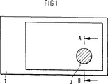
図1は、本発明によるデータキャリヤ1、この場合は紙幣を示す。通常、紙幣は、綿繊維および/または合成繊維から製造される紙からなる。本発明によれば、この紙幣はエンボス区域2を特徴とする。このエンボス区域2は、さらに、エンボスプロセスの前または後に紙幣に施せる1つ以上の光学的変動性コーティングを有しても差し支えない。
【0021】
図2は、線A−Bに沿ったエンボスの断面を示す。これによれば、エンボス2は傾斜平面3からなる。矢印4に沿ったエンボスの高さプロファイルは直線に従う。しかしながら、そのプロファイルは別の形態を示しても差し支えない。しかしながら、好ましくは、エンボスの高さプロファイルは、単純な数学的関数により記載することができる。
【0022】
図3は、棒の形態を有するエンボス5の平面図を示す。このエンボス5は、直接隣接する4つの部分区域6,7,8,9からなり、それによって、これら部分区域6,7,8は、傾斜平面の形態を有し、互いに隣りに配列されている。図2に類似して、矢印が、エンボスの高さが隆起している方向を示す。このことは、部分区域6,7および7,8それぞれの傾斜平面が、互いに対照的に配列されていることを示す。これとは対照的に、部分区域9は、傾斜平面の形態でエンボスされておらず、一定のエンボス高さを示す。
【0023】
部分区域6,8,9は輪郭として、部分区域7は、文字、例えば、英字の「I」の実(filled)区域として記載することもできる。このような英数字または図形を輪郭および実区域に分解することが特に有益であることが分かっている。輪郭および実区域の両方が、傾斜平面の形態にある少なくとも1つの部分区域を特徴付け、それによって、輪郭および実区域の傾斜平面が、互いに対照的に配列される。
【0024】
図4は、傾斜平面の配列および整列並びにエンボスの高さプロファイルのコースを示すために、図3の線A−Bに沿った断面を示す。部分区域7の傾斜は、エンボスの最大高さ値から、エンボスされていないデータキャリヤのレベルまで傾斜している。一定のエンボス高さによりエンボスされた部分区域9がこの区域に隣接している。さらに、部分区域6の傾斜平面を背景に見ることができ、これは、左手区域において、部分区域7の傾斜平面により覆われており、したがって、この区域では点線により示されている。
【0025】
図5は本発明によるエンボスのさらなる実施の形態を示す。この場合、エンボス10は、2つの部分区域11,12からなるが、これらの区域は、図3に示した部分区域とは対照的に、互いに隣り合って配列されていないが、外見上互いに重複している。しかしながら、この場合も、部分区域11,12の傾斜平面は、矢印により示されたように、互いに対照的に整列されている。
【0026】
このエンボス10のエンボスの高さプロファイルのコースが、図6に示されている線A−Bに沿った断面により示されている。ここで、部分区域11,12の傾斜平面が交差し、エンボス10が外見上V型のエンボスの高さプロファイルを有するのが分かる。点線により示された区域13,14は、重複せずに部分区域11および12において個々の傾斜平面の理論的コースを表すために単に描かれたものである。
【0027】
前記断面に沿った視角は比較的大きく変化するので、観察者により、図6に示したように、明らかに異なる入射角の元で、固定された観察点からエンボスが認識される。この事実のために、追加のコントラストが生じ、これにより、エンボスが目立ち、したがって、目にとってより容易に認識されるようになる。
【0028】
この効果は、エンボスの前記区域に光学的変動性コーティングを与えることによりさらに強調することができる。好ましくは、結合剤および光学的変動性顔料から実質的になるこのコーティングに、光学的変動性印刷インキを用いる。適切な光学的変動性顔料としては、例えば、視角を変えると色の変化を示す干渉コーティング顔料または液晶顔料が挙げられる。これらのインキが傾斜平面に施された場合、観察者には異なる入射角で各々の部分区域11,12の色が知覚される、すなわち、エンボスの高さプロファイルのために、エンボスの部分区域が、明らかに異なる視角で観察者にそれら自体を示し、それによって、エンボスの視角的知覚性を改善する、エンボス内の色の差が生じる。
【0029】
当然、いくつかの異なる印刷インキまたは1つの印刷インキをいくつかの異なる光学的変動性顔料と共に用いても差し支えない。これらの印刷インキはいかなる方法により施しても差し支えない。しかしながら、スクリーン印刷プロセスが優先的に用いられる。
【0030】
データキャリヤの材料は、任意のエンボス可能な材料からなっていても差し支えないが、好ましくは、任意の組成の紙が用いられる。しかしながら、異なる材料の多層ラミネートまたはプラスチック箔を本発明によりエンボスすることができる。これらは例えば、IDカードやパスポートに使用されている。
【図面の簡単な説明】
【図1】 図1は本発明によるデータキャリヤの概略図を示す
【図2】 図2は図1の線A−Bに沿った本発明によるデータキャリヤの断面図を示す
【図3】 図3は本発明によるエンボスの平面図を示す
【図4】 図4は図3の線A−Bに沿った断面図を示す
【図5】 図5は本発明によるエンボスの平面図を示す
【図6】 図6は図5の線A−Bに沿った断面図を示す[0001]
The present invention relates to data carriers such as securities, banknotes, ID cards or similar products featuring embossments in certain areas.
[0002]
For example, embossing securities such as stock certificates has always been customary. Such embossing given to paper is usually referred to as blind embossing. A common principle has been developed by the German securities exchange on the printing of securities, which stipulates some basic requirements on the form and implementation of such embossing ("Stock Exchange Guidelines"). For example, according to these stock trading guidelines, the embossment must be located in a specific area of the security. According to the stock exchange guidelines, these embossments also function as anti-counterfeiting features, so in order to make counterfeiting more difficult, they are not only in the form of letters, but preferably braided patterns. And include as complex a pattern as possible.
[0003]
As such, the advantage of push embossing is the simplicity of the verification, which can be performed purely by tactile means without the need for additional auxiliary equipment. Furthermore, due to the light / shade effect, observing its embossing gives a special three-dimensional visual impression. However, the visibility of the emboss is severely limited by diffusion or poor illumination.
[0004]
The invention is therefore based on the problem of proposing a data carrier with embossment with increased visual perception.
[0005]
A solution to this problem is based on the features of claim 1. Further development is the subject of the dependent claims.
[0006]
According to the invention, at least a part of the embossing is a sloping plane, i.e. the height or depth of the embossing starts at a maximum value relative to the rest of the surface of the data carrier in a predetermined direction, It must take the form of a decreasing plane. The reduction in emboss height or depth preferably follows a simple mathematical function such as a straight line, parabola or hyperbola. A continuous decrease in the form of a straight line, which is a typical inclination of the inclined plane, is preferred. For this reason, the term “inclined plane” is used as follows for a reduction in the height or depth of the embossing according to the invention, which is intended to be limited only to a typical linear reduction. It is not intended to include all other forms of slope transition. The embossing can be formed in such a manner that the embossing structure is raised relative to the non-embossed surface of the data carrier, or it can form a depression. A combination of both is possible within the emboss. The left and right dimensions and height or depth of the emboss are sized such that no optical diffraction effect occurs.
[0007]
According to a preferred embodiment, the embossment consists of several partial areas in the form of inclined planes. In this way, certain information to be formed on the emboss can be created from several inclined planes. In addition to the usual light and shade effects, the embossing as a whole becomes clearer and therefore perceptual, due to the variation in the height of the embossment within the partial area and the difference in the embossed height between the different partial areas. A contrast that is more easily perceptible to the human eye is formed. Very complex and complex embossing that additionally increases protection against counterfeiting as any desired letter, number, pattern or other picture or symbol can be formed with the help of a partial area in the form of an inclined plane A pattern can be formed. The dimensions of the individual inclined planes must simply be selected in such a way that each plane can be easily recognized at normal viewing distances without the need for any auxiliary equipment. Thereby, all of the inclined planes used can exhibit the same type of height profile. That is, the height / depth gradient of the embossment is the same in all partial areas, eg, the form is straight or parabolic. However, any combination of planes with different slopes can be used, thereby changing not only the profile of the height profile, but also the individual parameters within the profile. For example, it is possible to use an inclined plane in which all inclined planes show an embossed height profile in the form of a straight line, but these straight lines have different inclination angles. However, each embossment is characterized by at least one partial area or inclined plane whose inclination angle is less than 10 ° relative to the surface of the data carrier and has left and right dimensions in a maximum inclination direction greater than 1.5 mm. And In the case of a curved embossed height profile that does not exhibit a straight line shape, the tilt angle is created by the connecting line between the surface of the data carrier and the point having the starting point and the maximum embossed height or depth. Defined as between straight lines.
[0008]
The maximum embossed height or depth, which can be up to 250 μm, does not necessarily have to be the same for all inclined planes. In order to further increase the protection against counterfeiting, an additional embossing structure may be provided on the inclined plane.
[0009]
For clarity, the embodiment for raised embossing featuring an inclined plane with a straight height profile was selected for the following description.
[0010]
The embossing of the present invention can be manufactured using any type of embossing device. However, the embossing is preferably formed using intaglio stamping. For this purpose, an embossed structure is cut into the metal plate using known methods. A computer controlled process for producing such an intaglio printing plate is described, for example, in International Patent Application Publication No. WO 97/48555. During the printing process, the paper is pressed against the indentation of the engraved metal plate and is thus permanently deformed. These press plates are not filled with ink during the printing process, but they do not deform the document material, e.g. paper, i.e. only to form the emboss. Used.
[0011]
According to a preferred embodiment, the embossing consists of several partial areas in the form of inclined planes that are directly adjacent to each other and whose inclinations are opposite to each other. Thereby, the planes are recessed in a certain direction with a certain inclined plane, while the inclined planes arranged next to each other are raised in this direction in the form of wedges. Can be arranged together.
[0012]
According to a further embodiment, the inclined planes can also be adjacent to each other in such a way that they will overlap each other in appearance or will penetrate each other when extended. Two adjacent inclined planes thereby form, for example, a V-shaped height profile. Several, for example 3 or 4 directly adjacent inclined planes can be arranged and aligned with each other in such a way as to form a pyramid.
[0013]
Preferably, the data carrier can comprise several embossments at a distance from each other. According to a preferred embodiment, at least one inclined plane is continuous over several embossments, in particular adjacent embossments.
[0014]
According to a further preferred embodiment, at least one part of the embossing exhibits the form of an inclined plane, and furthermore, the embossed area of the data carrier has at least its optical effect varying depending on the viewing angle, Features a single coating or a series of coatings. Optically fluctuating materials such as interference coatings, liquid crystal coatings or coatings that exhibit diffractive structures exhibit a color change when the viewing angle changes, which cannot be reproduced by a copier. Therefore, these materials are often used as anti-duplication elements. When such a coating is provided in the embossed area of the present invention, an apparently perceived change in viewing angle occurs due to the height profile of the inclined plane, i.e. there is a color difference along the embossed height profile. And this makes the embossment stand out against the unembossed surroundings and therefore more easily perceived.
[0015]
If a highly reflective coating, such as a metal coating, is provided in the embossed area of the present invention, the highly reflective coating will appear very bright and shining at the incident angle, while at all other angles it will be more The effect is similar because it looks dark and unclear. Due to the height profile of the tilted plane, some embossed areas appear bright and shining at certain viewing angles, but others appear darker. In this way, additional contrast is generated that makes embossing more noticeable.
[0016]
The optically variable coating described above can be applied to the data carrier using any known method. For example, the coatings can be prepared on another substrate and then transferred to a data carrier using a transfer process. The prepared substrate material is brought into contact with the data carrier through an adhesive coating and optionally bonded to the data carrier under the application of heat and pressure. The substrate is then removed while the transferred coating remains on the data carrier.
[0017]
Depending on the material to be transferred, the substrate material must be treated with a different order of coating during preparation. For example, in the case of a diffractive structure, the substrate material is usually provided with a plastic coating in which the diffractive structure is embossed in the form of a relief. A thin coating of aluminum is then deposited on the relief and finally covered with an adhesive coating. However, under certain circumstances, additional coatings can be applied to the substrate material and transferred to the data carrier. Various methods for producing substrate materials with optically variable coatings are known in the prior art, for example from German Patent No. 2907186, U.S. Pat.No. 3,858,977, European Patent Application No. 0420262, European Patent No. 0435029. It has been.
[0018]
However, the coating can be applied in the form of a colored ink coating. In this case, the coating that produces the optical variability effect usually contains a pigment that is mixed with the printing ink binder and applied or printed by the squeegee on the data carrier. Interferometric coating pigments are sold, for example, by Merck under the name IRIODINE® or by BASF under the name PALIOSECURE®.
[0019]
Further embodiments and advantages of the present invention will be described with reference to the drawings. It should be noted that these drawings are not true to scale and are merely intended to illustrate the present invention.
[0020]
FIG. 1 shows a data carrier 1 according to the invention, in this case a banknote. Banknotes usually consist of paper made from cotton fibers and / or synthetic fibers. According to the invention, this bill is characterized by an embossed
[0021]
FIG. 2 shows a cross section of the embossment along line AB. According to this, the
[0022]
FIG. 3 shows a plan view of the embossing 5 having the form of a bar. The embossing 5 is composed of four directly adjacent
[0023]
The
[0024]
FIG. 4 shows a cross-section along line AB in FIG. 3 to show the course and alignment of the tilt planes and the course of the embossed height profile. The inclination of the
[0025]
FIG. 5 shows a further embodiment of the embossing according to the invention. In this case, the
[0026]
The course of the embossing height profile of this
[0027]
Since the viewing angle along the cross section changes relatively greatly, as shown in FIG. 6, the observer recognizes the emboss from the fixed observation point under a clearly different incident angle. This fact results in additional contrast, which makes the embossment noticeable and therefore easier to recognize for the eye.
[0028]
This effect can be further emphasized by providing an optically variable coating in the area of the embossment. Preferably, an optically variable printing ink is used for this coating consisting essentially of a binder and an optically variable pigment. Suitable optically variable pigments include, for example, interference coating pigments or liquid crystal pigments that exhibit a change in color when the viewing angle is changed. When these inks are applied to an inclined plane, the viewer perceives the color of each
[0029]
Of course, several different printing inks or one printing ink can be used with several different optically variable pigments. These printing inks can be applied by any method. However, the screen printing process is preferentially used.
[0030]
The data carrier material can be any embossable material, but preferably paper of any composition is used. However, multilayer laminates or plastic foils of different materials can be embossed according to the present invention. These are used for ID cards and passports, for example.
[Brief description of the drawings]
1 shows a schematic diagram of a data carrier according to the invention. FIG. 2 shows a cross-sectional view of a data carrier according to the invention along the line AB in FIG. Fig. 4 shows a plan view of the embossing according to the present invention. Fig. 4 shows a sectional view along the line AB in Fig. 3. Fig. 5 shows a plan view of the embossing according to the present invention. FIG. 6 shows a cross-sectional view along line AB in FIG.
Claims (16)
Applications Claiming Priority (3)
| Application Number | Priority Date | Filing Date | Title |
|---|---|---|---|
| DE19845552.6 | 1998-10-02 | ||
| DE19845552A DE19845552A1 (en) | 1998-10-02 | 1998-10-02 | Disk |
| PCT/EP1999/007215 WO2000020225A1 (en) | 1998-10-02 | 1999-09-29 | Data carrier |
Publications (3)
| Publication Number | Publication Date |
|---|---|
| JP2002526291A JP2002526291A (en) | 2002-08-20 |
| JP2002526291A5 JP2002526291A5 (en) | 2006-11-24 |
| JP4640889B2 true JP4640889B2 (en) | 2011-03-02 |
Family
ID=7883273
Family Applications (1)
| Application Number | Title | Priority Date | Filing Date |
|---|---|---|---|
| JP2000573562A Expired - Fee Related JP4640889B2 (en) | 1998-10-02 | 1999-09-29 | Data carrier |
Country Status (15)
| Country | Link |
|---|---|
| US (1) | US6712397B1 (en) |
| EP (1) | EP1117543B1 (en) |
| JP (1) | JP4640889B2 (en) |
| CN (1) | CN1108242C (en) |
| AR (1) | AR020680A1 (en) |
| AT (1) | ATE228941T1 (en) |
| AU (1) | AU754983B2 (en) |
| CA (1) | CA2345228A1 (en) |
| CZ (1) | CZ295320B6 (en) |
| DE (2) | DE19845552A1 (en) |
| ES (1) | ES2187199T3 (en) |
| PL (1) | PL347149A1 (en) |
| PT (1) | PT1117543E (en) |
| UA (1) | UA69425C2 (en) |
| WO (1) | WO2000020225A1 (en) |
Families Citing this family (28)
| Publication number | Priority date | Publication date | Assignee | Title |
|---|---|---|---|---|
| DE19963849A1 (en) * | 1999-12-30 | 2001-07-12 | Giesecke & Devrient Gmbh | Data carrier with printed security element |
| DE10015097A1 (en) * | 2000-03-28 | 2001-10-04 | Giesecke & Devrient Gmbh | Banknote paper and method for its printing, engraved printing plate for such a method and method for producing an engraved print- plate for use with such printing, to produce complex print images that are hard to counterfeit |
| SE516625C2 (en) * | 2000-06-20 | 2002-02-05 | Holmen Ab | Security paper / board and process for making them |
| GB0117096D0 (en) * | 2001-07-13 | 2001-09-05 | Qinetiq Ltd | Security label |
| US7063264B2 (en) | 2001-12-24 | 2006-06-20 | Digimarc Corporation | Covert variable information on identification documents and methods of making same |
| AU2002364036A1 (en) | 2001-12-24 | 2003-07-15 | Digimarc Id Systems, Llc | Laser etched security features for identification documents and methods of making same |
| US7728048B2 (en) | 2002-12-20 | 2010-06-01 | L-1 Secure Credentialing, Inc. | Increasing thermal conductivity of host polymer used with laser engraving methods and compositions |
| US7815124B2 (en) | 2002-04-09 | 2010-10-19 | L-1 Secure Credentialing, Inc. | Image processing techniques for printing identification cards and documents |
| US7694887B2 (en) | 2001-12-24 | 2010-04-13 | L-1 Secure Credentialing, Inc. | Optically variable personalized indicia for identification documents |
| CA2470600C (en) | 2001-12-24 | 2009-12-22 | Digimarc Id Systems, Llc | Systems, compositions, and methods for full color laser engraving of id documents |
| DE10201032A1 (en) | 2002-01-11 | 2003-07-24 | Giesecke & Devrient Gmbh | Steel intaglio printing process for producing a security document, as well as steel intaglio printing plate and semi-finished products therefor, and process for their production |
| US7824029B2 (en) | 2002-05-10 | 2010-11-02 | L-1 Secure Credentialing, Inc. | Identification card printer-assembler for over the counter card issuing |
| DE10234431A1 (en) * | 2002-07-29 | 2004-02-12 | Giesecke & Devrient Gmbh | Device and method for processing documents of value |
| US7804982B2 (en) | 2002-11-26 | 2010-09-28 | L-1 Secure Credentialing, Inc. | Systems and methods for managing and detecting fraud in image databases used with identification documents |
| EP1439076A1 (en) * | 2003-01-15 | 2004-07-21 | Kba-Giori S.A. | Security element for documents |
| US7763179B2 (en) * | 2003-03-21 | 2010-07-27 | Digimarc Corporation | Color laser engraving and digital watermarking |
| DE602004030434D1 (en) | 2003-04-16 | 2011-01-20 | L 1 Secure Credentialing Inc | THREE-DIMENSIONAL DATA STORAGE |
| DE10328744A1 (en) * | 2003-06-25 | 2005-01-13 | Metronic Ag | Print carrier with optically birefringent layer |
| EP1580020A1 (en) * | 2004-03-24 | 2005-09-28 | Kba-Giori S.A. | Intaglio printing plate |
| US20060146271A1 (en) * | 2005-01-04 | 2006-07-06 | Pennaz Thomas J | Universal display module |
| US7821794B2 (en) * | 2005-04-11 | 2010-10-26 | Aveso, Inc. | Layered label structure with timer |
| US7599192B2 (en) * | 2005-04-11 | 2009-10-06 | Aveso, Inc. | Layered structure with printed elements |
| GB2438383B (en) * | 2006-05-26 | 2008-10-08 | Rue De Int Ltd | Improvements in substrates |
| US8470431B2 (en) * | 2007-12-14 | 2013-06-25 | Kimberly Clark | Product with embossments having a decreasing line weight |
| NL2001466C2 (en) * | 2008-04-10 | 2009-10-13 | Konink Nl Munt N V | Authentication feature and method for manufacturing thereof. |
| FR2942811B1 (en) | 2009-03-04 | 2011-05-06 | Oberthur Technologies | SECURITY ELEMENT FOR DOCUMENT-VALUE. |
| FR2973398B1 (en) | 2011-03-30 | 2013-04-12 | Oberthur Technologies | SECURITY ELEMENT FOR VALUE DOCUMENT, MANUFACTURING METHOD, AND CORRESPONDING DOCUMENT |
| DE102011114647A1 (en) * | 2011-09-30 | 2013-04-04 | Giesecke & Devrient Gmbh | Security element with several optically variable structures |
Family Cites Families (13)
| Publication number | Priority date | Publication date | Assignee | Title |
|---|---|---|---|---|
| CH595664A5 (en) | 1975-11-17 | 1978-02-15 | Landis & Gyr Ag | |
| CH604146A5 (en) * | 1976-12-21 | 1978-08-31 | Landis & Gyr Ag | |
| DE3009097A1 (en) * | 1980-03-10 | 1981-09-24 | Jacob Ritter Kg, 6101 Brensbach | Ball pen publicity markings - are formed by thermal impressions and metallisation |
| DE8236980U1 (en) * | 1982-12-31 | 1985-06-13 | GAO Gesellschaft für Automation und Organisation mbH, 8000 München | Identification card |
| DE3741179A1 (en) | 1987-12-04 | 1989-06-15 | Gao Ges Automation Org | DOCUMENT WITH FALSE-PROOF SURFACE RELIEF AND METHOD FOR PRODUCING THE SAME |
| JPH0329877U (en) * | 1989-07-28 | 1991-03-25 | ||
| GB9025390D0 (en) * | 1990-11-22 | 1991-01-09 | De La Rue Thomas & Co Ltd | Security device |
| EP0710183B2 (en) * | 1993-06-08 | 2007-03-28 | Securency Pty. Ltd. | Embossing of banknotes or the like with security devices |
| DE4328413A1 (en) | 1993-08-24 | 1995-03-02 | Basf Magnetics Gmbh | Anticopy film |
| DE4421407C1 (en) * | 1994-06-18 | 1995-06-01 | Kurz Leonhard Fa | Area element with a three-dimensional regionally coated microstructure |
| DE4441198A1 (en) * | 1994-11-18 | 1996-05-23 | Giesecke & Devrient Gmbh | Data carrier and process equipment mfr. |
| US6749925B2 (en) | 1994-11-18 | 2004-06-15 | Giesecke & Devrient Gmbh | Data carrier |
| DE19541064A1 (en) * | 1995-11-03 | 1997-05-07 | Giesecke & Devrient Gmbh | Data carrier with an optically variable element |
-
1998
- 1998-10-02 DE DE19845552A patent/DE19845552A1/en not_active Withdrawn
-
1999
- 1999-09-29 EP EP99948895A patent/EP1117543B1/en not_active Expired - Lifetime
- 1999-09-29 CA CA002345228A patent/CA2345228A1/en not_active Abandoned
- 1999-09-29 AT AT99948895T patent/ATE228941T1/en active
- 1999-09-29 PL PL99347149A patent/PL347149A1/en not_active IP Right Cessation
- 1999-09-29 JP JP2000573562A patent/JP4640889B2/en not_active Expired - Fee Related
- 1999-09-29 CN CN99811575A patent/CN1108242C/en not_active Expired - Fee Related
- 1999-09-29 US US09/787,921 patent/US6712397B1/en not_active Expired - Fee Related
- 1999-09-29 DE DE59903678T patent/DE59903678D1/en not_active Expired - Lifetime
- 1999-09-29 PT PT99948895T patent/PT1117543E/en unknown
- 1999-09-29 CZ CZ20011189A patent/CZ295320B6/en not_active IP Right Cessation
- 1999-09-29 WO PCT/EP1999/007215 patent/WO2000020225A1/en active IP Right Grant
- 1999-09-29 AU AU61979/99A patent/AU754983B2/en not_active Ceased
- 1999-09-29 UA UA2001053026A patent/UA69425C2/en unknown
- 1999-09-29 ES ES99948895T patent/ES2187199T3/en not_active Expired - Lifetime
- 1999-09-30 AR ARP990104976A patent/AR020680A1/en active IP Right Grant
Also Published As
| Publication number | Publication date |
|---|---|
| EP1117543A1 (en) | 2001-07-25 |
| CZ20011189A3 (en) | 2002-08-14 |
| ES2187199T3 (en) | 2003-05-16 |
| CN1320084A (en) | 2001-10-31 |
| UA69425C2 (en) | 2004-09-15 |
| AR020680A1 (en) | 2002-05-22 |
| AU6197999A (en) | 2000-04-26 |
| EP1117543B1 (en) | 2002-12-04 |
| DE19845552A1 (en) | 2000-04-06 |
| JP2002526291A (en) | 2002-08-20 |
| ATE228941T1 (en) | 2002-12-15 |
| DE59903678D1 (en) | 2003-01-16 |
| AU754983B2 (en) | 2002-11-28 |
| CA2345228A1 (en) | 2000-04-13 |
| WO2000020225A1 (en) | 2000-04-13 |
| PL347149A1 (en) | 2002-03-25 |
| PT1117543E (en) | 2003-03-31 |
| CN1108242C (en) | 2003-05-14 |
| CZ295320B6 (en) | 2005-07-13 |
| US6712397B1 (en) | 2004-03-30 |
Similar Documents
| Publication | Publication Date | Title |
|---|---|---|
| JP4640889B2 (en) | Data carrier | |
| CA2694383C (en) | Security element having a plurality of optically variable structures | |
| AU2010219575B2 (en) | Security element for a value document | |
| US10300730B2 (en) | Methods of manufacturing image element arrays for security devices | |
| US8137899B1 (en) | Data support with an opticallly variable element | |
| CN103080816B (en) | Light variset | |
| CA2577246C (en) | Data carrier with an optically variable structure | |
| EP0710183B1 (en) | Embossing of banknotes or the like with security devices | |
| EP1716004B1 (en) | Security device | |
| TWI419799B (en) | Security device formed by printing with special effect inks | |
| CN101454165B (en) | Safety device and safety substrate comprising same | |
| CA2849424C (en) | Security element comprising a plurality of optically variable structures | |
| AU2002366437B2 (en) | Valuable document | |
| CN109153280B (en) | Optically variable security element | |
| ZA200301515B (en) | Data carrier, method for the production thereof and gravure printing plate. | |
| US10322601B2 (en) | Security element with effect pigments and an embossing structure and method for the production thereof | |
| MX2008016287A (en) | Security device. | |
| WO1998053999A1 (en) | Optically variable devices | |
| JP2003072219A (en) | Image forme | |
| ZA200403846B (en) | Valuable document |
Legal Events
| Date | Code | Title | Description |
|---|---|---|---|
| A521 | Request for written amendment filed |
Free format text: JAPANESE INTERMEDIATE CODE: A523 Effective date: 20060928 |
|
| A621 | Written request for application examination |
Free format text: JAPANESE INTERMEDIATE CODE: A621 Effective date: 20060928 |
|
| A131 | Notification of reasons for refusal |
Free format text: JAPANESE INTERMEDIATE CODE: A131 Effective date: 20100223 |
|
| A601 | Written request for extension of time |
Free format text: JAPANESE INTERMEDIATE CODE: A601 Effective date: 20100524 |
|
| A602 | Written permission of extension of time |
Free format text: JAPANESE INTERMEDIATE CODE: A602 Effective date: 20100531 |
|
| A521 | Request for written amendment filed |
Free format text: JAPANESE INTERMEDIATE CODE: A523 Effective date: 20100623 |
|
| A131 | Notification of reasons for refusal |
Free format text: JAPANESE INTERMEDIATE CODE: A131 Effective date: 20100713 |
|
| A521 | Request for written amendment filed |
Free format text: JAPANESE INTERMEDIATE CODE: A523 Effective date: 20100910 |
|
| TRDD | Decision of grant or rejection written | ||
| A01 | Written decision to grant a patent or to grant a registration (utility model) |
Free format text: JAPANESE INTERMEDIATE CODE: A01 Effective date: 20101026 |
|
| A01 | Written decision to grant a patent or to grant a registration (utility model) |
Free format text: JAPANESE INTERMEDIATE CODE: A01 |
|
| A61 | First payment of annual fees (during grant procedure) |
Free format text: JAPANESE INTERMEDIATE CODE: A61 Effective date: 20101125 |
|
| R150 | Certificate of patent or registration of utility model |
Free format text: JAPANESE INTERMEDIATE CODE: R150 |
|
| FPAY | Renewal fee payment (event date is renewal date of database) |
Free format text: PAYMENT UNTIL: 20131210 Year of fee payment: 3 |
|
| LAPS | Cancellation because of no payment of annual fees |