JP4640552B2 - Paper transport device and paper transport method - Google Patents
Paper transport device and paper transport method Download PDFInfo
- Publication number
- JP4640552B2 JP4640552B2 JP2008069742A JP2008069742A JP4640552B2 JP 4640552 B2 JP4640552 B2 JP 4640552B2 JP 2008069742 A JP2008069742 A JP 2008069742A JP 2008069742 A JP2008069742 A JP 2008069742A JP 4640552 B2 JP4640552 B2 JP 4640552B2
- Authority
- JP
- Japan
- Prior art keywords
- roller
- pinch roller
- feed roller
- paper
- sheet
- Prior art date
- Legal status (The legal status is an assumption and is not a legal conclusion. Google has not performed a legal analysis and makes no representation as to the accuracy of the status listed.)
- Expired - Fee Related
Links
Images


Landscapes
- Delivering By Means Of Belts And Rollers (AREA)
Description
本発明は、用紙搬送装置および用紙搬送方法に係わり、たとえばデジタル複写機、ファクシミリ装置あるいはスキャナで原稿の画像情報を読み取る読取位置の手前にフィードローラとピンチローラを配置した構造の装置で好適な用紙搬送装置および用紙搬送方法に関する。 BACKGROUND OF THE INVENTION 1. Field of the Invention The present invention relates to a sheet conveying apparatus and a sheet conveying method. For example, a sheet suitable for an apparatus having a structure in which a feed roller and a pinch roller are arranged in front of a reading position for reading image information of a document with a digital copying machine, a facsimile apparatus, or a scanner. The present invention relates to a transport device and a paper transport method.
スキャナ(画像読取装置)等の原稿搬送装置では、ローラを使用してシート状の原稿を所定の読取位置まで搬送し、1次元イメージセンサを用いて画像情報を読み取ることが広く行われている。このような原稿搬送装置では、原稿を読取位置までフィードローラとピンチローラの対によって搬送することが本発明の第1の関連技術として用いられることが多い。 2. Description of the Related Art In a document conveying device such as a scanner (image reading device), a sheet-like document is conveyed to a predetermined reading position using a roller and image information is read using a one-dimensional image sensor. In such a document conveying device, it is often used as the first related technique of the present invention to convey a document to a reading position by a pair of a feed roller and a pinch roller.
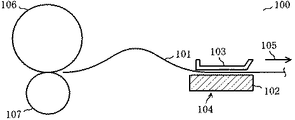
図6は、この第1の関連技術における原稿搬送装置の一例を表わしたものである。この原稿搬送装置100で原稿101は、プラテンガラス102とその上方に配置された白色背景板103を備えた読取部104の間を、この図に矢印で示した副走査方向105に搬送される。この搬送状態で、プラテンガラス102側に配置された図示しない1次元イメージセンサによって画像が副走査方向105と直交する主走査方向にライン単位で読み取られるようになっている。原稿101はプラテンガラス102よりも上流側に配置されたフィードローラ106と、これと転接するピンチローラ107の対によって搬送されることで、読取部104に送り込まれるようになっている。
FIG. 6 shows an example of a document conveying device in the first related technology. In this
このような本発明の第1の関連技術では、原稿101の後端がフィードローラ106とピンチローラ107の対から離れるときに、ピンチローラ107による原稿の押し出しが生じて、図示のように後端部に撓みが発生する現象が生じていた。これにより、原稿101の後端近傍を読取部104が読み取る際に、副走査方向105の搬送速度が不均一となり、「ピッチムラ」の画像が生じるという問題があった。
In such a first related art of the present invention, when the trailing edge of the
図7〜図9は、この「ピッチムラ」の画像の発生原因を説明するためのものである。図7〜図9で図6と同一部分には同一の符合を付している。 7 to 9 are diagrams for explaining the cause of the occurrence of the “pitch unevenness” image. 7 to 9, the same parts as those in FIG. 6 are denoted by the same reference numerals.
図7でフィードローラ106は、ゴムローラである。フィードローラ106は、図6で示した原稿搬送装置100内の図示しない所定の不動部材に回動自在に取り付けられており、図示しない駆動機構によって矢印111方向に回転する力を与えられている。ピンチローラ107は、簡略化して示したバネ112の一端に軸支されており、プラスチックで成形したプラスチックモールドローラとなっている。
In FIG. 7, the
この原稿搬送装置では、フィードローラ106が回転すると、その外周と接触する原稿101が副走査方向105に搬送される。ピンチローラ107は、バネ112によって矢印113方向としてのフィードローラ106方向に押し付けられている。したがって、ピンチローラ107は、原稿101の副走査方向105の移動に追随する形で、矢印114方向に回転することになる。
In this document transport device, when the
図8は、原稿101の後端がフィードローラ106とピンチローラ107の対から離れようとしている時点の様子を表わしたものである。この時点までピンチローラ107の周速度はフィードローラ106の周速度と同一となっている。
FIG. 8 shows a state at the time when the trailing edge of the
図9は、原稿101の後端がフィードローラ106を抜けた直後の状態を表わしたものである。ピンチローラ107は図8の状態から一時的にフィードローラ106からの拘束を解かれた状態となり、その慣性力とバネ112によって矢印113方向に移動する力が加わって原稿101の後端を矢印105方向に押し出すように回転する。この結果、原稿101の搬送速度が一時的に上昇することになる。
FIG. 9 shows a state immediately after the rear end of the
このような問題を解決するために、本発明の第2の関連技術として、用紙の後端がフィードローラとピンチローラが圧力による変形で面接触した領域としてのニップ領域を抜ける際にこれらのローラを強制的に離間させることが提案されている(たとえば特許文献1参照)。
この第2の関連技術によれば、図9のように、原稿101の後端がピンチローラ107とフィードローラ106のニップ領域を抜けるとき、ピンチローラ107が矢印113方向と反対方向に移動する。この機構によりピンチローラが原稿後端を押し出すという問題は解決する。しかしながら、このような機構を実現するためには、ピンチローラ107全体をバネ112に逆らって所定方向に短時間に移動させる駆動源としてのモータやソレノイド、動力伝達部品としてのシャフトやベルトといった新たな部品を必要とする。これにより、原稿搬送装置のコストが増大するだけでなく、これらの部品の占める空間が新たに必要となって装置の小型化を困難にするといった問題があった。
According to the second related technique, as shown in FIG. 9, when the trailing edge of the
以上、原稿搬送装置についての問題点を指摘したが、同様にシート状の用紙を搬送する他の用紙搬送装置でも同様の問題があった。 As mentioned above, the problems with the document conveying apparatus have been pointed out, but the same problems have been encountered with other sheet conveying apparatuses that similarly convey sheet-like sheets.
そこで本発明の目的は、フィードローラとピンチローラのニップ領域を用紙の後端が抜ける際の、この後端に対する押し出し現象を抑制することのできる用紙搬送装置および用紙搬送方法を提供することにある。 SUMMARY OF THE INVENTION Accordingly, an object of the present invention is to provide a sheet conveying apparatus and a sheet conveying method capable of suppressing an extruding phenomenon with respect to the trailing edge when the trailing edge of the sheet leaves the nip region between the feed roller and the pinch roller. .
本発明では、(イ)駆動系に接続されて回転するローラの外周部分を用紙の一方の面と接触させて回転方向に沿った力を与えるフィードローラと、(ロ)このフィードローラの下方にこのフィードローラと接離自在に配置され、その比重が少なくとも4以上となったピンチローラと、(ハ)前記したフィードローラとピンチローラの間に前記した用紙が存在する状態でピンチローラを前記した用紙の他方の面に圧接させる弾性部材とを用紙搬送装置に具備させる。 In the present invention, (a) a feed roller that is connected to a drive system and makes an outer peripheral portion of the roller contact with one surface of the paper to apply a force along the rotation direction, and (b) below the feed roller A pinch roller that is arranged so as to be able to contact with and separate from the feed roller and has a specific gravity of at least 4 and (c) the pinch roller described above in a state where the paper is present between the feed roller and the pinch roller. An elastic member that is brought into pressure contact with the other surface of the paper is provided in the paper transport device.
また、本発明の用紙搬送方法は、バネによる圧接で生じるピンチローラとこのピンチローラの上方に接離自在に配置されたフィードローラとのニップ領域を用紙が挟まれて搬送される際に、用紙の後端がこのニップ領域を抜ける時点で、前記したピンチローラが前記した用紙の後端の抜けにより生じる離間状態から前記したバネの復元によりフィードローラに再度接触するまでの時間を、前記した用紙の後端が前記したニップ領域を抜け始めてから完全に抜け切るまでの時間に比べて大きくなるように前記したピンチローラの重さを設定して用紙の搬送を行うことを特徴としている。 The sheet conveyance method of the present invention, when the nip region between the pinch roller and the upward separable freely arranged feed rollers of the pinch roller caused by the pressure contact sheet is conveyed pinched by the spring, the paper The time from when the pinch roller comes out of the nip region to the time when the pinch roller comes into contact with the feed roller again due to the restoration of the spring from the separation state caused by the removal of the rear end of the paper is described as follows. The sheet is conveyed by setting the weight of the pinch roller so as to be larger than the time until the rear end of the rear end starts to pass through the nip region and completely ends.
以上説明したように本発明によれば、フィードローラとその下方に接離自在に配置されたピンチローラとのニップ領域を用紙の後端が抜ける際の、この後端に対する押し出し現象を、特別の機構を設けることなく、抑制することができる。したがって、新たな機構を設けるためのコストアップを避けることができるだけでなく、用紙搬送装置の小型化の障害とならないという効果がある。 As described above, according to the present invention, when the trailing edge of the sheet passes through the nip region between the feed roller and the pinch roller disposed so as to be freely contactable and separable , the phenomenon of pushing out the trailing edge is specially detected. It can suppress, without providing a mechanism. Therefore, there is an effect that not only an increase in cost for providing a new mechanism can be avoided, but also an obstacle to miniaturization of the sheet conveying device is not obtained.
図1は、本実施の形態の画像形成装置における原稿搬送装置の部分を示したものである。原稿搬送装置200は、たとえばファクシミリ装置や複写機の上部部分として、図示しない読取部に原稿を順次送り込む装置である。この原稿搬送装置200の装置本体201の上部には、トレイ兼蓋部202が開閉自在に取り付けられている。
FIG. 1 shows a portion of a document conveying device in the image forming apparatus of the present embodiment. The
図2は、この原稿搬送装置のトレイ兼蓋部を開いた状態を表わしたものである。装置本体201の上部には、図示しない原稿を載置するためのプラテンガラス211が配置されており、その左端部の下方に1次元イメージセンサ(図示せず)を含んだ読取部(センサ側)212が往復動自在に配置されている。トレイ兼蓋部202におけるこの読取部212と対向する位置には、シート状の原稿を読み取る読取部(透光側)213が配置されており、これよりも原稿の搬送路の上流側に、ピンチローラ214が所定の間隔を置いて一列に配置されている。
FIG. 2 shows a state in which the tray / lid portion of the document conveying apparatus is opened. A
図3〜図5は、本実施の形態でフィードローラとピンチローラの間を原稿が搬送される様子を表わしたものである。これら図3〜図5は、図7〜図9と対応している。本実施の形態の場合、ピンチローラ214と転接するフィードローラ215は、直径が8ミリメートルのゴムローラとなっている。フィードローラ215のサイズおよび材質は図7に示したフィードローラ106と同一である。また、フィードローラ215の駆動系も、従来と同様である。
3 to 5 show how the document is conveyed between the feed roller and the pinch roller in this embodiment. 3 to 5 correspond to FIGS. 7 to 9. In the present embodiment, the
一方、ピンチローラ214は、簡略化して示したバネ221の一端に軸支されており、矢印222方向(フィードローラ215の方向)に押し付けられる力を与えられている。ピンチローラ214は、直径が4ミリメートルの円柱状に加工された金属ローラとなっている。金属としては、SUS(ステンレス鋼)あるいは真鍮が好適である。SUSは比重が7.82であり、真鍮は、銅70%、亜鉛30%の配合の場合、8.56である。他の金属でも比重がある程度大きいものであれば構わない。
On the other hand, the
このように本実施の形態のピンチローラ214は、図7に示した第1の関連技術のピンチローラ107と外形は同一である。ただし、第1の関連技術のピンチローラ107はプラスチック製のためにその比重が0.9前後であり、本実施の形態のピンチローラ214はこれに比べるとかなり重い。図3では、このピンチローラ214がフィードローラ215と転接して、原稿223を図に矢印で示した副走査方向224方向に搬送している。
Thus, the
図4は、原稿の後端がピンチローラとフィードローラのニップ領域を抜け出した直後の状態を表わしたものである。これに対応する図8の場合には、ピンチローラ107の重さが軽い。このため、ピンチローラ107自体が現在の位置に存在しようとする慣性力に対してバネ112が矢印222方向に移動させる力が比較的大きいことになり、ピンチローラ107は素早く移動する。この結果、原稿101の後端を押し出してしまう。
FIG. 4 shows a state immediately after the trailing edge of the document has slipped out of the nip region between the pinch roller and the feed roller. In the case of FIG. 8 corresponding to this, the weight of the
これに対して、本実施の形態の場合には、ピンチローラ214の自重がピンチローラ107と比較して8〜9倍も重くなる。このため、現在の位置に存在しようとする慣性力が遥かに大きくなって、ピンチローラ214の矢印222方向への変位の速度が大幅に遅くなる。この結果、ピンチローラ214は原稿223の後端部の動きに追随できず、取り残される。すなわち、原稿223の後端を矢印224方向に押し出すことができない。
On the other hand, in the case of the present embodiment, the weight of the
図5は、原稿が下流側の図示しない搬送系で更に搬送された状態を表わしたものである。この時点でピンチローラ214はフィードローラ215にかなり接近している。しかしながら、この時点で原稿223の後端は副走査方向224方向にかなり前進しており、その後端を矢印224方向に押し出すことができない。
FIG. 5 shows a state where the original is further conveyed by a conveyance system (not shown) on the downstream side. At this point, the
以上説明したように本実施の形態では、ピンチローラ214を比重の重い金属のローラに変えたので、特別の駆動系や伝達系といった機構を追加することなく、原稿223等の用紙の後端の一時的な押し出しの現象を回避あるいは抑制することができる。したがって、従来使用した原稿搬送装置の構成部品を一部交換するだけで、読み取り画像の「ピッチムラ」を抑えることができ、画質を向上させることができる。
As described above, in the present embodiment, the
以上の本発明の作用を別の観点から表現すると次のようになる。 The above operation of the present invention can be expressed from another viewpoint as follows.
バネ221による圧接で生じるピンチローラ214とフィードローラ215のニップ領域を原稿223が挟まれて搬送される際に、原稿223の後端がこのニップ領域を抜ける時点で、ピンチローラ214が原稿223の後端の抜けにより生じる離間状態からバネ221の復元によりフィードローラ215に再度接触するまでの時間を、原稿223の後端がニップ領域を抜け始めてから完全に抜け切るまでの時間に比べて大きくなるようにすること。これには、ピンチローラ214を、たとえば重金属の使用により、従来のゴムやプラスチックによるものよりも格段に重くする必要がある。
When the
なお、実施の形態では用紙搬送装置のうち、原稿の搬送を行う原稿搬送装置に本発明を適用したが、駆動ローラ(フィードローラ)と従動ローラ(ピンチローラ)を対として用紙の搬送を行うその他の用紙搬送装置にも本発明を同様に適用することが可能である。 In the embodiment, the present invention is applied to a document conveying device that conveys a document among the sheet conveying devices. However, the driving roller (feed roller) and the driven roller (pinch roller) are paired to convey the sheet. The present invention can be similarly applied to other paper transport apparatuses.
また、実施の形態ではピンチローラを金属ローラとしたが、主要部分が金属で構成され、外径部分あるいは内径部分がプラスチック等の他の材料で構成された混合部材によるローラに対しても本発明を同様に適用することができる。 In the embodiment, the pinch roller is a metal roller. However, the present invention is also applicable to a roller using a mixing member in which a main portion is made of metal and an outer diameter portion or an inner diameter portion is made of another material such as plastic. Can be applied as well.
本発明者は、ピンチローラを各種の金属で構成して比重に伴う慣性力との関係で発明の効果を検証した。これによれば、たとえば比重が2.7前後のアルミニウムでは、従来からロールとして多用されたプラスチックと比較して目立った効果がなかった。軽金属の部類でも比重が4以上となると、プラスチックと比較して重さが4倍以上あり、シート状部材の後端での一時的な押し出しの現象を回避あるいは抑制する効果が確認され、読み取り画像の「ピッチムラ」が大幅に減少した。ピンチローラの比重が7以上であれば、この効果が顕著に現われることも確認した。 The present inventor verified the effect of the invention in relation to the inertial force accompanying the specific gravity by configuring the pinch roller with various metals. According to this, for example, aluminum having a specific gravity of around 2.7 has no remarkable effect as compared with a plastic that has been frequently used as a roll. Even if the specific gravity of light metal is 4 or more, the weight is 4 times or more compared to plastic, and the effect of avoiding or suppressing the phenomenon of temporary extrusion at the rear end of the sheet-like member has been confirmed. The “pitch unevenness” of the It was also confirmed that this effect was remarkably exhibited when the specific gravity of the pinch roller was 7 or more.
鉄や多くのレアメタルは重金属の仲間であり、本発明の効果を有するが、さびやコストの面で多少問題があり、SUSや真鍮であれば、ロール全体を同一の材料として使用することができる。もちろん、鉄(比重は7.85)であってもメッキ等の他の材料の被覆によって実用上問題のないローラを提供することができる。 Iron and many rare metals are heavy metal companions and have the effects of the present invention, but have some problems in terms of rust and cost. If SUS or brass is used, the entire roll can be used as the same material. . Of course, even if it is iron (specific gravity is 7.85), the roller which does not have a problem in practical use can be provided by covering with other materials, such as plating.
また、実施の形態ではピンチローラ214を棒状のバネ221で弾性的に保持したが、他の同様な弾性部材を用いてもよいことは当然である。
Further, in the embodiment, the
200 原稿搬送装置
212、213 読取部
214 ピンチローラ
215 フィードローラ
221 バネ
223 原稿
200
Claims (6)
このフィードローラの下方にこのフィードローラと接離自在に配置され、その比重が少なくとも4以上となったピンチローラと、
前記フィードローラとピンチローラの間に前記用紙が存在する状態でピンチローラを前記用紙の他方の面に圧接させる弾性部材
とを具備することを特徴とする用紙搬送装置。 A feed roller that is connected to the drive system to bring the outer peripheral portion of the rotating roller into contact with one surface of the paper and applies a force along the rotation direction;
A pinch roller disposed below the feed roller so as to be in contact with and away from the feed roller and having a specific gravity of at least 4;
And a resilient member that presses the pinch roller against the other surface of the sheet in a state where the sheet exists between the feed roller and the pinch roller.
Priority Applications (1)
| Application Number | Priority Date | Filing Date | Title |
|---|---|---|---|
| JP2008069742A JP4640552B2 (en) | 2008-03-18 | 2008-03-18 | Paper transport device and paper transport method |
Applications Claiming Priority (1)
| Application Number | Priority Date | Filing Date | Title |
|---|---|---|---|
| JP2008069742A JP4640552B2 (en) | 2008-03-18 | 2008-03-18 | Paper transport device and paper transport method |
Publications (2)
| Publication Number | Publication Date |
|---|---|
| JP2009220989A JP2009220989A (en) | 2009-10-01 |
| JP4640552B2 true JP4640552B2 (en) | 2011-03-02 |
Family
ID=41238200
Family Applications (1)
| Application Number | Title | Priority Date | Filing Date |
|---|---|---|---|
| JP2008069742A Expired - Fee Related JP4640552B2 (en) | 2008-03-18 | 2008-03-18 | Paper transport device and paper transport method |
Country Status (1)
| Country | Link |
|---|---|
| JP (1) | JP4640552B2 (en) |
Families Citing this family (1)
| Publication number | Priority date | Publication date | Assignee | Title |
|---|---|---|---|---|
| CN110250601B (en) * | 2019-07-24 | 2024-10-11 | 电子科技大学中山学院 | Automatic forming production line for clean cup |
Family Cites Families (3)
| Publication number | Priority date | Publication date | Assignee | Title |
|---|---|---|---|---|
| JPH09292778A (en) * | 1996-04-24 | 1997-11-11 | Minolta Co Ltd | Image transfer device |
| JPH11157694A (en) * | 1997-09-26 | 1999-06-15 | Ricoh Co Ltd | Paper feeder |
| JP2004250135A (en) * | 2003-02-19 | 2004-09-09 | Konica Minolta Holdings Inc | Sheet feeding mechanism, light beam scanning device, and image forming apparatus |
-
2008
- 2008-03-18 JP JP2008069742A patent/JP4640552B2/en not_active Expired - Fee Related
Also Published As
| Publication number | Publication date |
|---|---|
| JP2009220989A (en) | 2009-10-01 |
Similar Documents
| Publication | Publication Date | Title |
|---|---|---|
| EP0994052A3 (en) | Sheet feeding apparatus, image forming apparatus having the same and image reading apparatus having the same | |
| JPS59149247A (en) | Automatic paper feeder | |
| US8740216B2 (en) | Document conveying apparatus and document conveying method | |
| JPH09150984A (en) | Paper conveying device | |
| JP4640552B2 (en) | Paper transport device and paper transport method | |
| CN100439222C (en) | paper transfer mechanism | |
| JP2007119244A (en) | Automatic document feeding device | |
| US10029867B2 (en) | Feeding device | |
| JP2011140396A (en) | Conveyance device, electronic equipment including the same, and conveying method | |
| JP6746967B2 (en) | Medium feeding device, image reading device, recording device | |
| NL1030709C2 (en) | Sheet transport device and printer provided with such a device. | |
| JP2001309118A (en) | Document feeder | |
| JP4249050B2 (en) | Paper feeding device and image forming apparatus | |
| JP4478632B2 (en) | Paper processing equipment | |
| JP2704031B2 (en) | Paper sheet take-out device | |
| JPH0259092B2 (en) | ||
| JP2008068995A (en) | Sheet conveying device | |
| JP2012116608A (en) | Method and device for transporting sheet, and sheet processing device | |
| JP6497750B2 (en) | Sheet transfer device | |
| JP4262114B2 (en) | Printing device | |
| JP2005179058A (en) | Sheet treatment device, automatic document feeder, and image forming device | |
| KR0135646B1 (en) | Paper feeder in an image forming apparatus using an electrophotographic processor | |
| JP2023030345A (en) | Image forming apparatus | |
| JPH1029734A (en) | Paper sheet separating device | |
| JP2007137530A (en) | Paper sheet conveying device |
Legal Events
| Date | Code | Title | Description |
|---|---|---|---|
| A977 | Report on retrieval |
Free format text: JAPANESE INTERMEDIATE CODE: A971007 Effective date: 20100629 |
|
| A131 | Notification of reasons for refusal |
Free format text: JAPANESE INTERMEDIATE CODE: A131 Effective date: 20100706 |
|
| A521 | Request for written amendment filed |
Free format text: JAPANESE INTERMEDIATE CODE: A523 Effective date: 20100901 |
|
| TRDD | Decision of grant or rejection written | ||
| A01 | Written decision to grant a patent or to grant a registration (utility model) |
Free format text: JAPANESE INTERMEDIATE CODE: A01 Effective date: 20101102 |
|
| A01 | Written decision to grant a patent or to grant a registration (utility model) |
Free format text: JAPANESE INTERMEDIATE CODE: A01 |
|
| A61 | First payment of annual fees (during grant procedure) |
Free format text: JAPANESE INTERMEDIATE CODE: A61 Effective date: 20101116 |
|
| R150 | Certificate of patent or registration of utility model |
Free format text: JAPANESE INTERMEDIATE CODE: R150 |
|
| FPAY | Renewal fee payment (event date is renewal date of database) |
Free format text: PAYMENT UNTIL: 20131210 Year of fee payment: 3 |
|
| S111 | Request for change of ownership or part of ownership |
Free format text: JAPANESE INTERMEDIATE CODE: R313111 |
|
| R350 | Written notification of registration of transfer |
Free format text: JAPANESE INTERMEDIATE CODE: R350 |
|
| LAPS | Cancellation because of no payment of annual fees |