JP4638552B1 - Aids for flower stands - Google Patents
Aids for flower stands Download PDFInfo
- Publication number
- JP4638552B1 JP4638552B1 JP2010147414A JP2010147414A JP4638552B1 JP 4638552 B1 JP4638552 B1 JP 4638552B1 JP 2010147414 A JP2010147414 A JP 2010147414A JP 2010147414 A JP2010147414 A JP 2010147414A JP 4638552 B1 JP4638552 B1 JP 4638552B1
- Authority
- JP
- Japan
- Prior art keywords
- flower
- auxiliary tool
- stem portion
- port
- insertion port
- Prior art date
- Legal status (The legal status is an assumption and is not a legal conclusion. Google has not performed a legal analysis and makes no representation as to the accuracy of the status listed.)
- Expired - Fee Related
Links
Images


Landscapes
- Supports For Plants (AREA)
- Cultivation Receptacles Or Flower-Pots, Or Pots For Seedlings (AREA)
Abstract
【課題】生花や造花に関わらず花を容易に花立てに固定可能で、風雨などで花が吹き飛ぶことを防止できる花立て用の補助具を提供すること。
【解決手段】筒状部材11と移動規制部材12とを備える。移動規制部材12は、筒状部材11の外周に設けられ、花立てに差し込まれると弾性変形して補助具の移動を規制する。筒状部材11は、ほぼ筒状の胴体部15と、上下の胴体上部16、胴体下部17とを有する。胴体上部16は、挿入口13を胴体部15よりも小さくするために上方につぼまった形状とされる。胴体下部17は、胴体部15の外周に沿った複数箇所から花立ての底に向けて延びて、先端部分を胴体部15の中心軸に近づけるために曲げられた複数の下部板バネからなり、胴体部15から下方につぼまった形状とされている。複数の下部板バネの先端部分によって挟持口14が挿入口13よりも小さくなるように形成されている。
【選択図】 図2To provide an auxiliary tool for a flower stand that can easily fix the flower to a flower stand regardless of whether it is a fresh flower or an artificial flower, and can prevent the flower from being blown off by wind and rain.
A tubular member 11 and a movement restricting member 12 are provided. The movement restricting member 12 is provided on the outer periphery of the cylindrical member 11, and is elastically deformed when it is inserted into the flower stand to restrict the movement of the auxiliary tool. The tubular member 11 has a substantially tubular body part 15, upper and lower body upper parts 16, and a body lower part 17. The body upper part 16 is shaped to be squeezed upward in order to make the insertion port 13 smaller than the body part 15. The body lower portion 17 is composed of a plurality of lower leaf springs that extend from a plurality of locations along the outer periphery of the body portion 15 toward the bottom of the flower stand and are bent to bring the tip portion closer to the central axis of the body portion 15. It is a shape that is squeezed downward from the body portion 15. The sandwiching port 14 is formed to be smaller than the insertion port 13 by the tip portions of the plurality of lower leaf springs.
[Selection] Figure 2
Description
本発明は、生花や造花などの花立て、および、花立てに花を固定する補助具に関する。特に、取り扱いが容易でインテリアとしても利用することができ、かつ、屋外で使用する場合に花が風などで飛ばされないように保持できる花立ての補助具に関する。 The present invention relates to a flower stand such as a fresh flower or an artificial flower, and an auxiliary tool for fixing the flower to the flower stand. In particular, the present invention relates to an auxiliary tool for a flower stand that is easy to handle, can be used as an interior, and can be held so that the flowers are not blown away by wind or the like when used outdoors.
近年、生花に替えて造花を墓碑などに供えることが増加している。遠隔地に居住する墓参者には、一旦供えた生花を後日挿し替えたり、取り去ったりすることの負担が大きく、生花が言わば放置された状態になるケースが増えて、これに伴った不都合が指摘されるようになったからである。
造花用の花立てに関する発明や考案としては、造花の茎部分を保持する内筒部分と、この内筒部分を花立てに着脱自在に固定する固定部分と、を有した花立て用の保持具が知られている(例えば特許文献1参照)。この保持具を簡単に説明すると、内筒部分の内径は、ほぼ茎部分の外径に一致していて、茎部分が嵌め込まれると、これをしっかりと保持する。また、固定部分は、内筒部分の外周の複数箇所に弾性材料で形成されている。内筒部分を花立てに挿入すると、固定部分が弾性変形して、内筒部分が花立てから抜け出ないようにする。内筒部分は細長い形状であり、これに嵌め込まれた茎部分は、内筒部分のほぼ全長の部分によって挟持されることになる。
In recent years, the use of artificial flowers for tombstones in place of fresh flowers is increasing. Grave attendants living in remote areas have a large burden of replacing or removing fresh flowers once offered, and the number of cases where fresh flowers are left unattended increases. Because it came to be done.
As an invention or a device related to a flower stand for artificial flowers, a holder for a flower stand having an inner cylinder part for holding a stem part of the artificial flower and a fixing part for detachably fixing the inner cylinder part to the flower holder. Is known (see, for example, Patent Document 1). Briefly describing this holder, the inner diameter of the inner cylinder portion substantially matches the outer diameter of the stem portion, and when the stem portion is fitted, it is firmly held. The fixed portion is formed of an elastic material at a plurality of locations on the outer periphery of the inner cylinder portion. When the inner tube portion is inserted into the flower stand, the fixed portion is elastically deformed so that the inner tube portion does not come out of the flower stand. The inner cylinder portion has an elongated shape, and the stem portion fitted into the inner cylinder portion is sandwiched by the substantially full length portion of the inner cylinder portion.
このような特許文献1記載の従来の保持具を用いれば、まず、内筒部分を花立てに挿入して、固定部分によって内筒部分が花立て内で移動できないように固定する。そして、内筒部分に造花の茎部分を嵌め込んで、保持具に造花をまっすぐに立てる。よって、墓碑に備え付けられている既存の花立てをそのまま利用して造花を立てることができる。
墓碑は通常屋外にあるため、保持具に保持された造花が風で吹き飛ばされないようにしたい。そのため造花の茎部分が保持具の内筒部分から抜け難くなるように、筒部分の内径を茎部分の外径にほぼ一致させるか、筒部分の内径の方が僅かに小さくなるように設定する。このようにして茎部分を内筒部分に堅く嵌め込むことができれば、ちょっとした風ですぐに造花が吹き飛ばされることはない。
If the conventional holder described in
Since the tombstone is usually outdoors, we want to prevent the artificial flowers held in the holder from being blown away by the wind. Therefore, the inner diameter of the tube portion is made to substantially match the outer diameter of the stem portion, or the inner diameter of the tube portion is set slightly smaller so that the stem portion of the artificial flower is difficult to come off from the inner tube portion of the holder. . If the stem part can be tightly fitted into the inner cylinder part in this way, the artificial flower will not be blown away with a little wind.
特許文献1に記載された従来の花立て用の保持具では、上記のように、内筒部分に造花の茎部分を差し込んでも、差し込み具合が緩いと風で造花だけ抜け飛んでしまうおそれがある。通常は、茎部分を内筒部分に堅く押し込んで固定すると言った使用方法になる。
しかしながら、茎部分が細長い内筒部分に堅く嵌め込まれた状態では、造花に風雨などの外力が繰り返して作用することによって、外力による負荷が内筒部分の上端付近の茎部分に何度も集中して掛かってしまい、茎部分がポキンッと折れてしまう可能性が生じる。従来の保持具は、風雨などによる造花そのものの損傷を避け得るものではなく、完全に満足のいく花立ての保持具を提供しているとは言えなかった。
In the conventional holder for flower arrangements described in
However, when the stem part is tightly fitted in the elongated inner cylinder part, external forces such as wind and rain repeatedly act on the artificial flowers, so that the load due to the external force is concentrated many times on the stem part near the upper end of the inner cylinder part. This can cause the stem part to break. Conventional holders cannot avoid damage to the artificial flowers themselves due to wind and rain, etc., and cannot be said to provide a completely satisfactory holder for flower stands.
また、特許文献1の保持具は、造花専用であり、造花ではなく生花を花立てに固定したい場合には別途、生花でも使用できる保持具を探さなければならなかった。
さらに、上記の保持具では、内筒部分が一定の内径寸法となるため、太い茎や細い茎の花には適用できない。また、複数本の茎を束ねて花立てに差したい場合にも、内筒部分の内径寸法を調整できるようにはなっていなかった。
In addition, the holder of
Furthermore, since the inner cylinder portion has a constant inner diameter in the above holder, it cannot be applied to a flower with a thick stem or a thin stem. In addition, when it is desired to bundle a plurality of stems and put them in a flower stand, the inner diameter of the inner cylinder portion cannot be adjusted.
本発明は、前記従来技術に鑑みなされたものであり、その解決すべき課題は、第一に、生花や造花に関わらず花を容易に固定可能で、風雨などで花が吹き飛ぶことを防止できる花立て用の補助具を提供することにある。第二に、風雨などの外力によって花の茎部分が破損してしまうことを防止できる花立て用の補助具を提供することにある。第三に、茎部分の太さを変えたり、花の量を増減させたりした場合にも適用できる花立て用の補助具を提供することにある。 The present invention has been made in view of the prior art, and the problem to be solved is, first of all, it is possible to easily fix a flower regardless of a fresh flower or an artificial flower, and it is possible to prevent the flower from blowing off due to wind and rain. It is to provide an auxiliary tool for flower arrangement. The second object is to provide an auxiliary tool for flower stand that can prevent the stem portion of the flower from being damaged by an external force such as wind and rain. A third object is to provide an auxiliary tool for a flower stand that can be applied even when the thickness of the stem portion is changed or the amount of flowers is increased or decreased.
前記課題を解決するために本発明の請求項1記載の花立て用の補助具は、生花または造花を筒状の花立てに固定するためのもので、花の茎部分に取り付けられた状態で茎部分ごと前記花立てに差し込まれる補助具であって、以下のことを特徴とする。
すなわち、本発明の補助具は、筒状部材と、移動規制部材とを備えて構成される。まず、筒状部材は、前記茎部分を挿入する挿入口、および、挿入された前記茎部分を挟持する挟持口を有するほぼ筒状の部材である。また、移動規制部材は、前記筒状部材の外周に設けられ、前記花立てに差し込まれた場合に前記筒状部材と前記花立て間で挟まれて弾性変形する部材から成り、かつ、生じる弾性力により前記花立ての内面を押して前記筒状部材の該軸方向への移動を規制する。
具体的には、前記筒状部材は、該軸方向に沿って順番に、前記挿入口を形成する胴体上部と、胴体部と、前記挟持口を形成する胴体下部とから成る。
前記胴体上部は、前記胴体部から前記挿入口に向けてつぼまった形状とされる。また、前記胴体下部は、前記胴体部の外周に沿った複数箇所から前記挟持口に向けて延びて、かつ、先端部分を該筒状部材の中心軸に近づけるように曲げられた複数の下部板材から成り、これら複数の下部板材によって前記胴体部から前記挟持口に向けてつぼまった形状とされる。
そして、前記挟持口は、前記挿入口の大きさよりも小さく形成されており、かつ、前記挿入口から挿入される茎部分を該挟持口に押し込んだ場合に前記複数の下部板材の弾性変形により僅かに開いて、押込まれた前記茎部分の一部を弾性力で挟持することを特徴とする。
In order to solve the above-mentioned problem, an auxiliary tool for flower arrangements according to
That is, the auxiliary tool of the present invention includes a cylindrical member and a movement restricting member. First, the cylindrical member is a substantially cylindrical member having an insertion port for inserting the stem portion and a clamping port for clamping the inserted stem portion. Further, the movement restricting member is provided on the outer periphery of the tubular member, and includes a member that is elastically deformed by being sandwiched between the tubular member and the flower stand when inserted into the flower stand. The inner surface of the flower stand is pushed by force to restrict the movement of the cylindrical member in the axial direction.
Specifically, the cylindrical member includes, in order along the axial direction, an upper body portion that forms the insertion port, a body portion, and a lower body portion that forms the clamping port.
The upper part of the body is shaped to be squeezed from the body part toward the insertion port. In addition, the lower part of the body extends from a plurality of locations along the outer periphery of the body part toward the clamping port, and a plurality of lower plate members bent so that a tip end portion thereof approaches the central axis of the cylindrical member The plurality of lower plate members form a shape that is squeezed from the body portion toward the clamping port.
The clamping port is formed smaller than the size of the insertion port, and slightly when the stem portion inserted from the insertion port is pushed into the clamping port due to elastic deformation of the plurality of lower plate members. It is characterized in that a part of the stalk portion that is opened and held is held by elastic force.
この発明によれば、生花や造花に関わらず、花の茎部分に補助具を取り付けて、茎部分と一緒に花立てに差せば、花を花立てに固定することができる。すなわち、補助具は花立ての筒部に嵌め込まれて移動を規制され、かつ、花の茎部分が補助具にしっかりと挟持されるから、花立てに差された花が風雨などで簡単に飛ぶようなことがなくなる。
上記の構成の補助具を用いる場合には、まず、生花や造花などの茎部分を筒状部材の一方の口である上側の挿入口から挿入して、他方の口である下側の挟持口まで通す。茎部分を挟持口に押し込むと、弾性変形する複数の下部板材(板バネに相当する。)の先端部分で形成された挟持口が僅かに広がる。この時に生じる板バネの弾性変形によって、挟持口に差し込まれた茎部分が板バネの先端部分でしっかりと挟まれるから、茎部分から補助具が簡単に抜け落ちることはない。板バネの弾性変形を利用するので、茎部分の太さを変えたり、花の量を増減させたりした場合にも適用できる。
さらに、茎部分と一緒に補助具が花立てに挿入するだけで、移動規制部材の弾性変形により補助具が花立てに保持されるので、簡単に花を花立てに固定でき、強風が吹いても花ごと補助具が花立てから抜け出ることがない。
また、胴体上部が上方につぼまった形状であるから、上側の挿入口は、胴体部の断面の大きさよりも小さく形成される。一方で、挿入口は、下側の挟持口の大きさよりは大きい。つまり、挿入口の大きさは、挿入される茎部分の外径寸法よりも大きく、また、複数本の茎を挿入する場合は、茎を束ねた状態の外径寸法よりも大きくなるように設定されることになる。よって、下側の挟持口が挟持する一部分だけで、花の茎部分が補助具に保持される。一方、挿入口の付近では茎部分と挿入口の内周縁との隙間が生じるため、ちょうど挟持口を支点として花の茎部分がある程度自由に傾けるようになっている。従って、花が風雨などの外力を繰り返し受けたとしても、外力の負荷が茎部分の一箇所に集中することなく、茎部分が容易に折損してしまうことがない。
According to this invention, a flower can be fixed to a flower stand by attaching an auxiliary tool to the stem portion of the flower and inserting it into the flower stand together with the stem portion regardless of whether it is a fresh flower or an artificial flower. In other words, since the auxiliary tool is fitted into the tube part of the flower stand and the movement is restricted, and the stem portion of the flower is firmly clamped by the auxiliary tool, the flower inserted in the flower stand can easily fly due to wind and rain. Such a thing disappears.
When using the auxiliary tool configured as described above, first, stem portions such as fresh flowers and artificial flowers are inserted from the upper insertion port, which is one of the cylindrical members, and the lower holding port, which is the other mouth. Pass through. When the stem portion is pushed into the sandwiching opening, the sandwiching opening formed by the tip portions of a plurality of lower plate members (corresponding to leaf springs) that are elastically deformed slightly expands. Due to the elastic deformation of the leaf spring that occurs at this time, the stem portion inserted into the clamping port is firmly pinched by the tip portion of the leaf spring, so that the auxiliary tool does not easily fall out of the stem portion. Since the elastic deformation of the leaf spring is used, it can also be applied when the thickness of the stem portion is changed or the amount of flowers is increased or decreased.
Furthermore, just by inserting the auxiliary tool into the flower stand together with the stem part, the auxiliary tool is held in the flower stand by the elastic deformation of the movement restricting member, so that the flower can be easily fixed to the flower stand and the strong wind blows Even the flowers and auxiliary equipment will not come out of the flower stand.
In addition, since the upper part of the body is squeezed upward, the upper insertion port is formed smaller than the cross-sectional size of the body part. On the other hand, the insertion port is larger than the size of the lower clamping port. In other words, the size of the insertion opening is set to be larger than the outer diameter size of the stem portion to be inserted, and when inserting a plurality of stems, the size is set to be larger than the outer diameter size of the bundled stems. Will be. Therefore, the flower stem portion is held by the auxiliary tool only at a portion where the lower holding port holds. On the other hand, there is a gap between the stem portion and the inner peripheral edge of the insertion port in the vicinity of the insertion port, so that the flower stem portion can be freely tilted to some extent with the pinching port as a fulcrum. Therefore, even if the flower repeatedly receives external force such as wind and rain, the load of the external force is not concentrated on one part of the stem part, and the stem part is not easily broken.
また、請求項2記載の花立て用の補助具では、前記胴体上部は、前記胴体部の外周に沿った複数箇所から前記挿入口に向けて延びて、かつ、先端部分を前記筒状部材の中心軸に近づけるように曲げられた複数の上部板材から成り、これら複数の上部板材によって前記胴体部から前記挿入口に向けてつぼまった形状とされる。そして、前記挿入口に挿入された花に風雨などの外力が加わって、該花の茎部分が傾いた場合に、前記茎部分の傾動に応じて前記上部板材の少なくとも一枚が弾性変形して、前記外力のエネルギーが吸収されることが好ましい。
この発明によれば、筒状部材の胴体上部について、胴体下部と同様に複数枚の上部板材(板バネに相当する。)で構成するので、風雨などの外力を一枚もしくは数枚の板バネのみで吸収できる。すなわち、胴体上部の板バネは、茎部分を挟持するためのものではなく、前述のように茎部分をある程度自由に傾動できるようにするためにある。しかし、胴体上部が複数の板バネで構成されていないとすると、風雨などで花が繰り返し揺れて茎部分が傾斜する都度、風雨などの外力が補助部の全体に作用するから、補助具が段々と持ち上げられてしまい、最終的には花立てから花ごと抜け出してしまうおそれもある。本発明では、胴体上部を複数枚の板バネで形成したから、風雨などの外力のエネルギーが一部の板バネで吸収される。その結果、外力が補助具全体に作用することが起こらなくなり、補助具が花立てから抜け落ちる可能性も低くなる。
Further, in the auxiliary tool for flower arrangement according to claim 2, the upper part of the trunk extends from a plurality of locations along the outer periphery of the trunk part toward the insertion port, and a tip part of the cylindrical member is extended. It consists of a plurality of upper plate members bent so as to approach the central axis, and is formed into a shape that is squeezed from the body portion toward the insertion port by the plurality of upper plate members. When an external force such as wind and rain is applied to the flower inserted into the insertion opening and the stem portion of the flower is tilted, at least one of the upper plate members is elastically deformed according to the tilt of the stem portion. The energy of the external force is preferably absorbed.
According to the present invention, the upper part of the body of the tubular member is composed of a plurality of upper plate members (corresponding to leaf springs) in the same manner as the lower part of the body. Can only be absorbed. That is, the leaf spring at the upper part of the trunk is not for sandwiching the stem portion, but for allowing the stem portion to tilt freely to some extent as described above. However, if the upper part of the body is not composed of a plurality of leaf springs, each time the flower is repeatedly shaken by wind and rain and the stem part tilts, external force such as wind and rain acts on the entire auxiliary part, so the auxiliary tool gradually May be lifted up and eventually fall out of the flower stand. In the present invention, since the upper part of the body is formed by a plurality of leaf springs, energy of external force such as wind and rain is absorbed by some leaf springs. As a result, the external force does not act on the entire assisting tool, and the possibility that the assisting tool falls off the flower stand is reduced.
また、請求項3記載の花立て用の補助具では、前記筒状部材は、弾性を有する一枚の板材を、該筒状部材の前記胴体上部、前記胴体部および前記胴体下部が一体形状となるように加工して形成されていることが好ましい。
この発明によれば、弾性を有する一枚の板バネという単一素材で筒状部材の全体を形成できるので、製造時間の短縮および製造コストの低減を図ることができる。
Moreover, in the auxiliary tool for flower arrangements according to claim 3, the cylindrical member is made of a single plate material having elasticity, and the upper part of the body, the body part and the lower part of the body of the tubular member are integrally formed. it is preferred that processed and are formed to be.
According to this invention, since the whole cylindrical member can be formed with a single material called a single leaf spring having elasticity, the manufacturing time and the manufacturing cost can be reduced.
また、請求項4記載の花立て用の補助具では、前記移動規制部材は、前記胴体部の外周の複数箇所から上下方向に延びる細長い板バネで形成されていることが好ましい。
この発明によれば、移動規制部材を細長い板バネで形成したので、花立ての内径寸法に応じて板バネの広がり程度を調整することが容易となり、異なる内径の花立てにも適用できる。
Moreover, in the auxiliary tool for flower arrangements according to claim 4, it is preferable that the movement restricting member is formed of an elongated leaf spring extending in the vertical direction from a plurality of locations on the outer periphery of the body portion.
According to the present invention, since the movement restricting member is formed of an elongated leaf spring, it becomes easy to adjust the extent of spreading of the leaf spring in accordance with the inner diameter size of the flower stand, and it can be applied to flower stands having different inner diameters.
また、請求項5記載の花立て用の補助具は、前記筒状の筒状部材と、該筒状部材の外周に設けられ、前記花立ての口を覆うための板状の蓋部材とを備える。該蓋部材は、風雨などを受けても該補助具全体が花ごと倒れない程度の重量を有する。また、前記筒状部材は、前記胴体部で上下に分割形成されて、前記蓋部材の中央部に設けられた貫通孔を挟んで該蓋部材に取り付けられていることが好ましい。 Also, aid for Hanatate in claim 5, said tubular cylindrical member, provided on the outer periphery of the cylindrical member, and a plate-shaped lid member for covering the mouth of the Hanatate Prepare. The lid member has a weight that prevents the entire auxiliary tool from falling down with the flower even when it receives wind and rain. Moreover, it is preferable that the said cylindrical member is divided | segmented up and down by the said trunk | drum, and is attached to this cover member on both sides of the through-hole provided in the center part of the said cover member.
この発明によれば、蓋部材を風雨などで花が倒れない程度の重量になるように形成したので、この蓋部材を花立ての口部分に載置するだけで、蓋部材が重石の役目を果たし、筒状部分で挟持された花を花立てにしっかりと固定することができる。 According to the present invention, since the lid member is formed so as to have a weight that does not cause the flower to fall down due to wind and rain, the lid member functions as a weight by simply placing the lid member on the mouth portion of the flower stand. As a result, the flowers sandwiched between the cylindrical portions can be firmly fixed to the flower stand.
以下、図面に基づき本発明の好適な実施形態について説明する。
第一実施形態
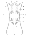
図1に本発明の第一実施形態にかかる花立て用の補助具の具体的な使用方法の一例を示す。補助具10は、同図(A)のように例えば造花などの茎部分Sに取り付けられた状態で、同図(B)のように茎部分Sと一緒に筒状の花立て20に差し込まれる。このような非常に簡単な方法で、生花または造花を花立て20に固定することができる。花立て20は、墓碑などで供え物を載せる台などに予め設置されている筒状の花立てを例示したが、形状についてはこれに限られず、墓石に円柱状の穴を開けて形成された花立て用の穴にも適用できる。また、屋外のものに限らず、卓上用の花立てや、店舗などの装飾用の花立てなどにも適用できる。
Preferred embodiments of the present invention will be described below with reference to the drawings.
First Embodiment FIG. 1 shows an example of a specific method for using an auxiliary tool for flower arrangement according to a first embodiment of the present invention. The
補助具10の具体的な構成を図2〜図5に基づいて説明する。補助具10は、図2の正面図のように、茎部分が挿入される筒状部材11と、その外周に設けられた4本又は、複数本の細長い板バネ12(移動規制部材)とに大別される。
筒状部材11は、図中の上下の両端に口を有したほぼ筒状の部材である。上側の口は、茎部分が挿入される挿入口13であり、この挿入口13から差し込まれた茎部分を下側の挟持口14まで通すことができる。以降、筒状部材11を、中央のほぼ筒状の胴体部15、この胴体部15の上下に形成された胴体上部16と胴体下部17に区分して説明する。
The specific structure of the
The
図2の矢視III−IIIで示す胴体部15の横断面図を図3に示す。胴体部15は、同図のように円環状の断面形状を有する(断面部分を斜め線のハッチングで示す)。この円環状の内側には、上からみた胴体下部17の形状および挟持口14の形状が見える。胴体部15の外周には、90度の中心角ピッチで4箇所又は、所定の中心角ピッチで複数箇所に細長い板バネ12が溶接されている。図3では、4本の板バネ12を矩形断面で示す。
FIG. 3 shows a cross-sectional view of the
<胴体上部>
胴体上部16は、胴体部15から花立ての口部分に向けて(図2中の上方向へ)つぼまった形状となっている。挿入口は胴体上部16の上端付近に形成されており、挿入口13の大きさが胴体部15の断面の大きさよりも小さくなっている。この胴体上部16は、胴体部15の外周に沿った8箇所又は、複数箇所から上側に向けて延びる8枚又は、複数枚の上側板バネからなる。8枚又は、複数枚の上側板バネは、互いに等間隔に並んでいる。各先端部分を胴体部15の中心軸に近づけるために、上側板バネは、この中心軸に向かって緩やかに彎曲している。さらに、上側板バネの先端部分の四分の一程度の範囲は逆方向に彎曲して、先端部分がほぼ水平方向になるまで開いている。
<Upper fuselage>
The body
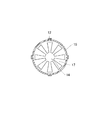
胴体上部16を上方から見た平面図を図4に示す。上側板バネ16A〜16Hが、ちょうど咲き始めた花びらのように放射状に開いている。同図より、8枚又は、複数枚の上側板バネ16A〜16Hの上端付近の彎曲している部分によって挿入口13が形成されているのが判る。このように、胴体上部16は、花のつぼみの上側部分の形状に似ている。
上側板バネ16A〜16Hの幅寸法、つまり胴体部15の外周方向に沿った幅寸法は、先端部分に向けてほぼ一様となっている。また、上側板バネ16A〜16Hの先端部分は半円形に加工されている。
FIG. 4 shows a plan view of the
The width dimensions of the
<胴体下部>
胴体下部17は、図2のように、下側の挟持口14の大きさを胴体部15の断面の大きさよりも小さく、更には上側の挿入口13の大きさよりも小さくするために、胴体部15から花立ての底に向けて(図2中の下方向へ)つぼまった形状となっている。挟持口14は、胴体下部17の下端付近に形成されている。
胴部下部17は、胴体部15の外周に沿った8箇所又は、複数箇所から下側に向けて延びる8枚又は、複数枚の下側板バネからなる。8枚又は、複数枚の下側板バネは、互いに等間隔に並んでいて、その下端部分を胴体部の中心軸に近づけるために、中心軸に向かって彎曲している。また、下端部分の僅か手前の部分から先は、逆方向に彎曲している。下端部分だけを外側に折り返すように曲げることによって、使用者が花を取り外す時に容易に茎部分を抜けるようにした。胴部下部17は、花のつぼみの下側部分の形状に似ている。
<Lower trunk>
As shown in FIG. 2, the fuselage
The trunk | drum
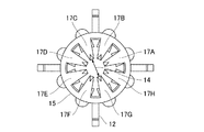
胴体下部17を下方から見た底面図を図5に示す。8枚又は、複数枚の下側板バネ17A〜17Hがつぼみの下半分の形状をしていて、その下端付近の彎曲によって挟持口14が形成されているのが判る。
下側板バネ17A〜17Hの幅寸法、つまり胴体部15の外周方向に沿った幅寸法は、下端部分に向けて徐々に狭くなっていて、その先端部分は尖っている。ただし、この先端部分で使用者が怪我をしないように、尖った先端部分には小さな丸みが施されている。
FIG. 5 shows a bottom view of the body
The width dimension of the
<製造方法>
図6に基づいて、筒状部材11の製造方法を簡単に説明する。筒状部材11の素材には、厚さ寸法が0.05mm〜2mmの範囲であるバネ用ステンレス鋼帯などを用いる。
まず、一枚の鋼帯を、例えば図6で示す展開した形状となるように加工する。つまり、胴体部15になる帯状部分と、その左側に半円形状の先端を有する8枚又は、複数枚の上側板バネ16部分と、右側に三角形状の8枚又は、複数枚の下側板バネ17部分とが一体形状となるように加工する。そして中央の胴体部15になる部分を曲げ加工して、図中の胴体部15になる部分の上下の端面15A、15B同士を接合することで、ほぼ円筒の胴体部15を形成する。
次に、上側板バネ16と下側板バネ17をそれぞれの形状に彎曲させる曲げ加工を行う。この際、筒状部材11の上下をつぼみ状の形状にするために、適宜、絞り加工を実施する。
<Manufacturing method>
Based on FIG. 6, the manufacturing method of the
First, one steel strip is processed so as to have, for example, a developed shape shown in FIG. That is, the belt-like portion that becomes the
Next, a bending process for bending the
このように一枚の鋼帯から加工された筒状部材11には、胴体部15の外周に4本又は、複数本の細長い板バネ12が接合されて、補助具10が完成する。4本又は、複数本の板バネ14は、胴体部15の4つ又は、複数の接合箇所21(図6中のハッチングで示す部分)に接合される。4つ又は、複数の接合箇所21は、図6左の上側板バネ16を形成するための切り込み18と、同図右の下側板バネ17を形成するための切り込み19とのほぼ真ん中に位置する部分となる。
上記の接合箇所21に細長い板バネ12を接合することによって、図2の補助具10の状態から上側板バネ16または下側板バネ17を外側に大きく広げたとしても、細長い板バネ12と干渉しないで済む。よって、茎部分を筒状部材11に挿入したり、逆に抜き取ったりする作業を楽に行うことができる。
In this way, the
Even if the
なお、上側および下側板バネ16、17の強度を確保するため、図6にて符号22、23で示す各板バネの一対の辺を130度程度、外側に折り返してもよい。このようにすれば、筒状部材11に挿入される茎部分を傷付けることなく、板バネ16、17が補強され、耐久性も向上する。
In order to secure the strength of the upper and
<外周の細長い板バネ>
4本又は、複数本の細長い板バネ12は、図2の胴体部15の外周に沿って等ピッチに配置されている。胴体部15に対する接合箇所は前述の図6に示した通りである。各板バネ12は、胴体部15から上下方向に延びている。また、補助具10を花立てに収納させた状態で、板バネ12の各先端部が花立ての内面に接するように広がっている。
4本又は、複数本の板バネ12は、図1(B)のように花立て20に差し込まれた状態では、筒状部材11と花立て20との隙間で弾性変形して、4本又は、複数本の板バネ12の全ての先端部が花立て20の内面を押した状態になる。よって、花を上下に押し引きして補助具10を花立て20の内部で移動させようとしても、補助具10と花立て20間で生じる摩擦力によって補助具10の移動が規制される。つまり、風雨程度の外力では、花が花立て20から抜け出すことがなく、4本又は、複数本の細長い板バネ12が移動規制部材として機能する。
<Elongated leaf spring on the outer periphery>
Four or a plurality of
Four or a plurality of
本実施形態にかかる花立ての補助具10は概略以上のように構成され、以下にその作用について説明する。
まず、図2にて、筒状部材11の上下の口(挿入口13、挟持口14)について説明する。筒状部材11の上側の挿入口13は、胴体上部16を構成する8枚又は、複数枚の上側板バネの先端部分のうち、最もくびれた部分によって形成される。また、筒状部材11の下側の挟持口14は、胴体下部17を構成する8枚又は、複数枚の下側バネ板材の先端部分のうち、最もくびれた部分によって形成される。
The flower
First, the upper and lower ports (
本実施形態においては、複数本を束ねた茎部分を挿入口13から挿入して、挟持口14に押し込むと、8枚又は、複数枚の下側板バネ17A〜17Hの弾性変形によって挟持口14が僅かに開いた状態になる。この時に生じる下側板バネ17A〜17Hの弾性力により、押し込まれた茎の一部がしっかりと挟持されるから、茎部分から補助具10が簡単に外れることはない。そして、茎部分と一緒に補助具10が花立てに挿入されると、4本又は、複数本の細長い板バネ12の弾性変形により、補助具10が花立てに保持されるため、強風が吹いても補助具10が花ごと抜け出すことがない。
In the present embodiment, when a stem portion of a plurality of bundles is inserted from the
また、本実施形態においては、挿入口13を胴体部15の断面の大きさよりも小さく形成し、かつ、下側の挟持口14よりは大きく形成した。つまり、挿入口13の大きさは、挿入される茎部分の外径寸法よりも大きくなるように設定される。なお、複数本の茎を束ねて挿入する場合は、束ねた状態の茎の外径寸法よりも大きくなるように挿入口13の開き具合を設定できる。よって、茎部分は、下側の挟持口14で挟持される部分のみで保持されることになる。挿入口13の内径寸法は茎部分の外径寸法よりも大きく設定されているから、茎部分と挿入口13の縁との間にある程度の隙間が生じて、花の茎部分がある程度自由に傾けるようになっている。従来の保持具のように、茎部分を所定長さの内筒などに嵌め込んで保持する場合、花が風雨で吹かれると、その外力の負荷が円筒の入り口付近の茎部分に集中する。すると、花に風雨などの外力が繰り返し作用しるため、従来の保持具では茎部分が容易に折損してしまう可能性があった。これに対して本発明では、茎部分の一箇所を挟持口14が挟持して、この部分よりも上方の挿入口13ではある程度茎部分を自由に傾斜可能にしたので、茎部分が容易に折損することを防ぐことができる。
In the present embodiment, the
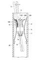
さらに、本実施形態では、胴体上部16についても胴体下部17と同様に複数枚の上側板バネ16A〜16Hで構成したから、風雨などの外力が一枚もしくは数枚の上側板バネで吸収されることになる。上側板バネ16A〜16Hは、茎部分を挟持するためのものではなく、前述のように茎部分をある程度自由に傾動可能にするためのものである。しかし、胴体上部16を複数の板バネで形成しない場合、風雨で花が繰り返し揺れて茎部分が傾斜する都度、風雨などの外力が補助部10の全体に作用して、補助具10が段々と持ち上げられてしまい、最終的には花立て20から花ごと抜け出してしまう可能性がある。これに対して本発明では、胴体上部16を複数枚の上側板バネで形成したから、風雨などの外力のエネルギーを一部の上側板バネで吸収することができる。このような胴体上部16の作用を図7に基づいて説明する。すなわち、上側の挿入口13から挿入されて、下側の挟持口14で茎部分Sが保持されている花に、風雨などの外力Fが加わった場合に、茎部分Sの傾動に応じて胴体上部16のうちの一枚の上側板バネ16Dだけが弾性変形することによって、外力のエネルギーが吸収される。この結果、外力が補助具10全体に作用することにはならず、補助具10が花立て20から抜け落ちる可能性も低くなる。
Further, in the present embodiment, the body
また、本実施形態においては、細長い板バネ12を、胴体部15の外周の4箇所又は、複数箇所から上下方向に延びるように接合したから、板バネ12の先端部分同士の間隔を自在に変えることが可能となり、花立て20の内径寸法に応じて先端部分の開き具合を調整すれば、内径寸法の異なる花立てにも同一の補助具10を使用できる。
以上の説明は、一本の茎に補助具10を取り付ける場合にも、複数本の茎を束ねた状態にして補助部10を取り付ける場合にも、同様となる。
Moreover, in this embodiment, since the elongate leaf |
The above description is the same when the
なお、外周の細長い板バネ12は、内部の筒状部材11と同様にステンレス鋼帯のような板状の弾性部材を加工して製造されるが、補助具10を花立て20に確実に固定することを重視して、外周の板バネ12の方には筒状部材11よりも硬めの弾性部材を用いた方がよい。一方、内部の筒状部材11は挿入する茎部分Sの外径寸法の適用範囲を広げることを重視するために、柔らかめの弾性部材を使用して、茎部分Sの細いものから太いものまで幅広く挟持できるようにした方がよい。
The
以上のように、本実施形態の花立て用の補助具10を用いれば、花を立てる際に、補助具10を茎部分Sと一緒に花立てに差し込むだけで、花を花立て20に固定することができるので、取り扱いが非常に簡単である。すなわち、補助具10は花立て20の筒部に嵌め込まれて移動を規制され、かつ、花の茎部分Sをしっかりと挟持するから、花立て20に差された花が風雨などで簡単に吹き飛ぶようなことを防げる。
As described above, if the
なお、本実施形態では、図1(B)の使用例に限らず、図8に示す横断面図のように、筒状部材11の内部に花弁を有する花の茎部分S1を挿入して、筒状部材11の外部に緑などの茎部分S2を差し込むといった使用方法もできる。
In the present embodiment, not only the use example of FIG. 1 (B) but also inserting a flower stem portion S1 having a petal inside the
第二実施形態
図9は、本発明の第二実施形態に係る花立ての補助具を示す側面図である。
本実施形態の補助具110は前述の図2で示した補助具10と一部共通する構成を有するが、筒状部材111が上下に分割された状態で形成されている点と、前述の4本又は、複数本の細長い板バネ12の代わりに、花立て20の蓋として使用される板状の蓋部材112を備えている点が大きく異なっている。ここでは、前述と異なる部材について説明する。
Second Embodiment FIG. 9 is a side view showing an auxiliary tool for flower stand according to a second embodiment of the present invention.
The assisting
図10は、補助具110の構造を説明するための分解側面図である。同図のように、筒状部材111の上半分は、貫通孔を有する雄ネジ部115Aと、この雄ネジ部115Aの上側に接合された複数枚の上側板バネ116とを備える。雄ネジ部115Aの貫通孔と上端の挿入口113とは同一の中心軸を有する。また、筒状部材111の下半分は、貫通孔を有する雌ネジ部115Bと、この雌ネジ部115Bの下側に接合された複数枚の下側板バネ117とを備える。雌ネジ部115Bの貫通孔と下端の挟持口114とは同一の中心軸を有する。
板状の蓋部材112の中央部には円形穴118が形成されており、この円形穴118を挟んで上方から雄ネジ部115Aと下方から雌ネジ部115Bとが螺合するようになっている。蓋部材には、家紋などを表示可能な垂直板119が着脱可能に取り付けられており、補助具110を墓碑などの花立てに用いる場合に役立つ。
FIG. 10 is an exploded side view for explaining the structure of the
A
本実施形態において特徴的なことは、蓋部材112が、花立て20の口部分に載置された状態で、花が風雨などを受けても倒れない程度の重量を有することにある。つまり、蓋部材112が重石の役目を果たし、筒状部分111で挟持された花を花立てにしっかりと固定することができて、前記実施形態と同様の効果を奏することができる。
What is characteristic in the present embodiment is that the
なお、前記第一実施形態で説明した補助具10については、単独で花立てとして使用することもできる。例えば、図1(A)で示す状態で、花の茎部分Sが4本又は、複数本の板バネ12の下端よりも下にならないように、補助具10の位置を調整して、そのまま食卓などの台の上に立てることで、インテリアとして使用することもできる。
In addition, about the
本発明の花立て用の補助具は、墓碑などの既存の花立てに花を固定するために利用されるだけでなく、あらゆる筒状の花立てに花を固定するための補助具として利用できる。例えば、店舗などの装飾用の花を固定する場合にも有効となる。また、アクリル製などの透明な花立てに使用すれば、つぼみ状に形成された円筒部分がインテリアとしての装飾効果を発揮する。さらに、補助具を単独で花立てとして使用することもできる。 The flowering aid of the present invention can be used not only to fix flowers to existing flower stands such as tombstones, but also to help fix flowers to any cylindrical flower stand. . For example, it is also effective when fixing decorative flowers in stores and the like. Moreover, if it is used for a transparent flower stand made of acrylic or the like, a cylindrical portion formed in a bud shape exhibits a decorative effect as an interior. Furthermore, the auxiliary tool can be used alone as a flower stand.
10 補助具
11 筒状部材
12 細長い板バネ(移動規制部材)
13 挿入口
14 挟持口
15 胴体部
16 胴体上部
16A〜16H 上側板バネ(胴体上部の複数の上部板材)
17 胴体下部
17A〜17H 下側板バネ(胴体下部の複数の下部板材)
20 花立て
112 蓋部材
S 花の茎部分
DESCRIPTION OF
13
17 Body
20 Flower stand 112 Lid member S Flower stem
Claims (5)
前記茎部分を挿入する挿入口、および、挿入された前記茎部分を挟持する挟持口を有するほぼ筒状の筒状部材と、
前記筒状部材の外周に設けられ、前記花立てに差し込まれた場合に前記筒状部材と前記花立て間で挟まれて弾性変形する部材から成り、かつ、生じる弾性力により前記花立ての内面を押して前記筒状部材の該軸方向への移動を規制する移動規制部材と、を備え、
前記筒状部材は、該軸方向に沿って順番に、前記挿入口を形成する胴体上部と、胴体部と、前記挟持口を形成する胴体下部とから成り、
前記胴体上部は、前記胴体部から前記挿入口に向けてつぼまった形状とされ、
前記胴体下部は、前記胴体部の外周に沿った複数箇所から前記挟持口に向けて延びて、かつ、先端部分を該筒状部材の中心軸に近づけるように曲げられた複数の下部板材から成り、これら複数の下部板材によって前記胴体部から前記挟持口に向けてつぼまった形状とされ、
前記挟持口は、前記挿入口の大きさよりも小さく形成されており、かつ、前記挿入口から挿入される茎部分を該挟持口に押し込んだ場合に前記複数の下部板材の弾性変形により僅かに開いて、押込まれた前記茎部分の一部を弾性力で挟持することを特徴とする花立て用の補助具。 For fixing fresh flowers or artificial flowers to a cylindrical flower stand, an auxiliary tool inserted into the flower stand together with the stem portion in a state attached to the stem portion of the flower,
A substantially cylindrical tubular member having an insertion port for inserting the stem portion, and a clamping port for clamping the inserted stem portion;
The inner surface of the flower stand is formed by a member that is provided on the outer periphery of the tubular member and is elastically deformed by being sandwiched between the tubular member and the flower stand when inserted into the flower stand. A movement restricting member that restricts the movement of the cylindrical member in the axial direction by pushing
The cylindrical member, in order along the axial direction, comprises a fuselage upper part that forms the insertion port, a fuselage part, and a fuselage lower part that forms the clamping port,
The upper part of the body is shaped to be squeezed from the body part toward the insertion port,
The lower portion of the body is composed of a plurality of lower plate members that extend from a plurality of locations along the outer periphery of the body portion toward the clamping port and that are bent so that the tip portion approaches the central axis of the cylindrical member. , And a shape that is squeezed from the body portion toward the clamping port by the plurality of lower plate materials,
The clamping port is formed smaller than the size of the insertion port, and slightly opens due to elastic deformation of the plurality of lower plate members when a stem portion inserted from the insertion port is pushed into the clamping port. A part of the pressed stem portion is clamped with an elastic force.
前記胴体上部は、前記胴体部の外周に沿った複数箇所から前記挿入口に向けて延びて、かつ、先端部分を前記筒状部材の中心軸に近づけるように曲げられた複数の上部板材から成り、これら複数の上部板材によって前記胴体部から前記挿入口に向けてつぼまった形状とされ、
前記挿入口に挿入された花に風雨などの外力が加わって、該花の茎部分が傾いた場合に、前記茎部分の傾動に応じて前記上部板材の少なくとも一枚が弾性変形して、前記外力のエネルギーが吸収されることを特徴とする花立て用の補助具。 The auxiliary tool for flower stand according to claim 1,
The upper part of the body is composed of a plurality of upper plate members that extend from a plurality of locations along the outer periphery of the body part toward the insertion port and are bent so that the tip end portion is close to the central axis of the cylindrical member. In addition, the plurality of upper plate members are shaped to be squeezed from the body portion toward the insertion port,
When an external force such as wind and rain is applied to the flower inserted into the insertion opening and the stem portion of the flower is tilted, at least one of the upper plate members is elastically deformed according to the tilt of the stem portion, An auxiliary tool for flower arrangements characterized by absorbing the energy of external force.
前記移動規制部材は、前記胴体部の外周の複数箇所から上下方向に延びる細長い板バネで形成されていることを特徴とする花立て用の補助具。 In the auxiliary tool for flower arrangements in any one of Claim 1 to 3,
The movement restricting member is an auxiliary tool for flower arrangement, wherein the movement restricting member is formed of elongated leaf springs extending vertically from a plurality of locations on the outer periphery of the body portion.
前記茎部分を挿入する挿入口、および、挿入された前記茎部分を挟持する挟持口を有するほぼ筒状の筒状部材と、
前記筒状部材の外周に設けられ、前記花立ての口を覆うための板状の蓋部材と、を備え、
前記筒状部材は、該軸方向に沿って順番に、前記挿入口を形成する胴体上部と、胴体部と、前記挟持口を形成する胴体下部とから成り、
前記胴体上部は、前記胴体部から前記挿入口に向けてつぼまった形状とされ、
前記胴体下部は、前記胴体部の外周に沿った複数箇所から前記挟持口に向けて延びて、かつ、先端部分を該筒状部材の中心軸に近づけるように曲げられた複数の下部板材から成り、これら複数の下部板材によって前記胴体部から前記挟持口に向けてつぼまった形状とされ、
前記挟持口は、前記挿入口の大きさよりも小さく形成されており、かつ、前記挿入口から挿入される茎部分を該挟持口に押し込んだ場合に前記複数の下部板材の弾性変形により僅かに開いて、押込まれた前記茎部分の一部を弾性力で挟持し、
前記蓋部材は、風雨などを受けても該補助具全体が花ごと倒れない程度の重量を有し、
前記筒状部材は、前記胴体部で上下に分割形成されて、前記蓋部材の中央部に設けられた貫通孔を挟んで該蓋部材に取り付けられていることを特徴とする花立て用の補助具。 For fixing fresh flowers or artificial flowers to a cylindrical flower stand, an auxiliary tool inserted into the flower stand together with the stem portion in a state attached to the stem portion of the flower,
A substantially cylindrical tubular member having an insertion port for inserting the stem portion, and a clamping port for clamping the inserted stem portion;
Provided on an outer periphery of the tubular member, and a plate-shaped lid member for covering the mouth of the Hanatate,
The cylindrical member, in order along the axial direction, comprises a fuselage upper part that forms the insertion port, a fuselage part, and a fuselage lower part that forms the clamping port,
The upper part of the body is shaped to be squeezed from the body part toward the insertion port,
The lower portion of the body is composed of a plurality of lower plate members that extend from a plurality of locations along the outer periphery of the body portion toward the clamping port and that are bent so that the tip portion approaches the central axis of the cylindrical member. , And a shape that is squeezed from the body portion toward the clamping port by the plurality of lower plate materials,
The clamping port is formed smaller than the size of the insertion port, and slightly opens due to elastic deformation of the plurality of lower plate members when a stem portion inserted from the insertion port is pushed into the clamping port. And sandwiching a part of the pressed stem part with an elastic force,
The lid member has a weight that prevents the entire auxiliary tool from falling together with the flower even when it receives wind and rain,
The tubular member is divided into upper and lower parts at the body portion, and is attached to the lid member with a through hole provided in a central portion of the lid member. Ingredients.
Priority Applications (1)
| Application Number | Priority Date | Filing Date | Title |
|---|---|---|---|
| JP2010147414A JP4638552B1 (en) | 2010-06-29 | 2010-06-29 | Aids for flower stands |
Applications Claiming Priority (1)
| Application Number | Priority Date | Filing Date | Title |
|---|---|---|---|
| JP2010147414A JP4638552B1 (en) | 2010-06-29 | 2010-06-29 | Aids for flower stands |
Publications (2)
| Publication Number | Publication Date |
|---|---|
| JP4638552B1 true JP4638552B1 (en) | 2011-02-23 |
| JP2012012775A JP2012012775A (en) | 2012-01-19 |
Family
ID=43768694
Family Applications (1)
| Application Number | Title | Priority Date | Filing Date |
|---|---|---|---|
| JP2010147414A Expired - Fee Related JP4638552B1 (en) | 2010-06-29 | 2010-06-29 | Aids for flower stands |
Country Status (1)
| Country | Link |
|---|---|
| JP (1) | JP4638552B1 (en) |
Cited By (1)
| Publication number | Priority date | Publication date | Assignee | Title |
|---|---|---|---|---|
| CN102764009A (en) * | 2012-07-31 | 2012-11-07 | 苏州苏鼎产品设计有限公司 | Flower vase |
Family Cites Families (13)
| Publication number | Priority date | Publication date | Assignee | Title |
|---|---|---|---|---|
| JPS5078595U (en) * | 1973-11-19 | 1975-07-08 | ||
| JPS5078596U (en) * | 1973-11-19 | 1975-07-08 | ||
| JPS5885053U (en) * | 1981-12-07 | 1983-06-09 | 川田 茂 | Flower vase support |
| JPS6179970U (en) * | 1985-10-24 | 1986-05-28 | ||
| JPH01131625A (en) * | 1987-08-25 | 1989-05-24 | Eiichi Tashiro | Portable flower pot |
| JPH01159760U (en) * | 1988-04-25 | 1989-11-06 | ||
| JPH02252870A (en) * | 1989-03-24 | 1990-10-11 | Masashi Takeda | Installed flowerpot exclusively used for tombstone |
| JPH0432152U (en) * | 1990-07-16 | 1992-03-16 | ||
| JPH09317249A (en) * | 1996-06-03 | 1997-12-09 | Fumio Terada | Flower stand container for gravestone |
| JP3881744B2 (en) * | 1997-04-23 | 2007-02-14 | 株式会社 アイエム | Cut flower holder |
| JP2004204511A (en) * | 2002-12-25 | 2004-07-22 | Bc Seisakusho:Kk | Artificial flower holder for flower stand |
| JP3838214B2 (en) * | 2003-03-31 | 2006-10-25 | 清満 深澤 | Artificial flower stand |
| JP2009197420A (en) * | 2008-02-19 | 2009-09-03 | Koji Nakamura | Auxiliary implement for flower stand for grave |
-
2010
- 2010-06-29 JP JP2010147414A patent/JP4638552B1/en not_active Expired - Fee Related
Cited By (1)
| Publication number | Priority date | Publication date | Assignee | Title |
|---|---|---|---|---|
| CN102764009A (en) * | 2012-07-31 | 2012-11-07 | 苏州苏鼎产品设计有限公司 | Flower vase |
Also Published As
| Publication number | Publication date |
|---|---|
| JP2012012775A (en) | 2012-01-19 |
Similar Documents
| Publication | Publication Date | Title |
|---|---|---|
| US5331725A (en) | Rod clip | |
| US9833529B2 (en) | Sterilization cassette systems, instrument retention systems for a use with a sterilization cassette, and configurable instrument retention members for use therewith | |
| US20090062078A1 (en) | Flexible Enclosure For A Recreational Structure | |
| US12171173B2 (en) | Flower stem insertion device for forming flower bouquets | |
| JP4638552B1 (en) | Aids for flower stands | |
| WO2015076507A1 (en) | Multifunctional support for crops | |
| US20130227882A1 (en) | Plant training and removal apparatus | |
| US8689367B2 (en) | Adjustable Toilet Seat Handle | |
| US7310909B2 (en) | Silk flower holder | |
| US4890730A (en) | Elastic band holder | |
| US20210120934A1 (en) | Ponytail Holder | |
| GB2467521A (en) | Frame connector | |
| JP3881744B2 (en) | Cut flower holder | |
| JP5600855B1 (en) | Fresh flower fixture | |
| JP3167867U7 (en) | ||
| JP2023049780A (en) | bonfire stand | |
| KR20160064430A (en) | Artificial eyelashes auxiliary equipment | |
| CN216527938U (en) | Multifunctional paper card holder | |
| CN201767359U (en) | Book supporting rod arranged on desk | |
| CN210630370U (en) | Support for assisting plant hybridization | |
| JP3159813U (en) | Auxiliary plant cultivation equipment | |
| JP3005181B2 (en) | Living tool | |
| US20080163886A1 (en) | Comb with smooth comb hair portion | |
| JP4505215B2 (en) | Joint structure | |
| JP3119340U (en) | Card stand |
Legal Events
| Date | Code | Title | Description |
|---|---|---|---|
| TRDD | Decision of grant or rejection written | ||
| A01 | Written decision to grant a patent or to grant a registration (utility model) |
Free format text: JAPANESE INTERMEDIATE CODE: A01 Effective date: 20101116 |
|
| A01 | Written decision to grant a patent or to grant a registration (utility model) |
Free format text: JAPANESE INTERMEDIATE CODE: A01 |
|
| A61 | First payment of annual fees (during grant procedure) |
Free format text: JAPANESE INTERMEDIATE CODE: A61 Effective date: 20101125 |
|
| FPAY | Renewal fee payment (event date is renewal date of database) |
Free format text: PAYMENT UNTIL: 20131203 Year of fee payment: 3 |
|
| R150 | Certificate of patent or registration of utility model |
Free format text: JAPANESE INTERMEDIATE CODE: R150 |
|
| LAPS | Cancellation because of no payment of annual fees |