JP4636618B2 - Simulation device, surgical robot control system using the same, and program for simulation device - Google Patents
Simulation device, surgical robot control system using the same, and program for simulation device Download PDFInfo
- Publication number
- JP4636618B2 JP4636618B2 JP2006266103A JP2006266103A JP4636618B2 JP 4636618 B2 JP4636618 B2 JP 4636618B2 JP 2006266103 A JP2006266103 A JP 2006266103A JP 2006266103 A JP2006266103 A JP 2006266103A JP 4636618 B2 JP4636618 B2 JP 4636618B2
- Authority
- JP
- Japan
- Prior art keywords
- organ
- external force
- mesh
- stress
- unit
- Prior art date
- Legal status (The legal status is an assumption and is not a legal conclusion. Google has not performed a legal analysis and makes no representation as to the accuracy of the status listed.)
- Expired - Fee Related
Links
- 238000004088 simulation Methods 0.000 title claims description 34
- 210000000056 organ Anatomy 0.000 claims description 139
- 239000013598 vector Substances 0.000 claims description 60
- 238000006073 displacement reaction Methods 0.000 claims description 47
- 239000000470 constituent Substances 0.000 claims description 39
- 239000000463 material Substances 0.000 claims description 32
- 238000004364 calculation method Methods 0.000 claims description 29
- 230000008859 change Effects 0.000 claims description 26
- 238000000034 method Methods 0.000 claims description 22
- 238000003384 imaging method Methods 0.000 claims description 15
- 230000006378 damage Effects 0.000 claims description 13
- 230000006870 function Effects 0.000 claims description 6
- 210000004185 liver Anatomy 0.000 description 49
- 238000001356 surgical procedure Methods 0.000 description 10
- 210000005036 nerve Anatomy 0.000 description 7
- 210000004204 blood vessel Anatomy 0.000 description 6
- 238000006243 chemical reaction Methods 0.000 description 6
- 230000008569 process Effects 0.000 description 5
- 238000010586 diagram Methods 0.000 description 4
- 238000002324 minimally invasive surgery Methods 0.000 description 4
- 238000002091 elastography Methods 0.000 description 3
- 239000011159 matrix material Substances 0.000 description 3
- 230000003925 brain function Effects 0.000 description 2
- 238000002591 computed tomography Methods 0.000 description 2
- 238000001514 detection method Methods 0.000 description 2
- 210000004738 parenchymal cell Anatomy 0.000 description 2
- 238000003745 diagnosis Methods 0.000 description 1
- 238000002059 diagnostic imaging Methods 0.000 description 1
- 230000000694 effects Effects 0.000 description 1
- 210000003494 hepatocyte Anatomy 0.000 description 1
- 238000009434 installation Methods 0.000 description 1
- 238000002357 laparoscopic surgery Methods 0.000 description 1
- 230000007246 mechanism Effects 0.000 description 1
- 238000012986 modification Methods 0.000 description 1
- 230000004048 modification Effects 0.000 description 1
- 230000008520 organization Effects 0.000 description 1
- 230000001575 pathological effect Effects 0.000 description 1
- 230000007170 pathology Effects 0.000 description 1
- 230000010363 phase shift Effects 0.000 description 1
- 230000011218 segmentation Effects 0.000 description 1
- 230000035807 sensation Effects 0.000 description 1
- 230000002792 vascular Effects 0.000 description 1
Images


Description
本発明は、低侵襲手術用のマニピュレータ等の処置具により臓器等の器官に外力が付加されたときに、当該器官の各部分の応力状態や変形状態を推定することのできるシミュレーション装置及びこれに関連する装置、システム及びプログラムに関する。 The present invention relates to a simulation apparatus capable of estimating the stress state and deformation state of each part of an organ when an external force is applied to the organ such as an organ by a treatment tool such as a manipulator for minimally invasive surgery, and the like. The present invention relates to related apparatuses, systems, and programs.
近年、大きな切開を要さずに患者への負担を少なくする低侵襲手術が注目されており、この低侵襲手術を行うためのマスタースレーブ方式の手術支援ロボットが種々研究開発されている。この手術支援ロボットは、内視鏡や処置具等を保持するマニピュレータと、このマニピュレータを動作させるロボットアームと、このロボットアームに対して術者が動作指令を与える操作装置とを備えており、当該操作装置を術者が操作すると、当該操作に応じてロボットアームが所望の動作を行うようになっている。 In recent years, attention has been focused on minimally invasive surgery that reduces the burden on a patient without requiring a large incision, and various master-slave type surgery support robots for performing this minimally invasive surgery have been researched and developed. The surgery support robot includes a manipulator that holds an endoscope, a treatment tool, and the like, a robot arm that operates the manipulator, and an operation device that gives an operation command to the robot arm by an operator. When the operator operates the operating device, the robot arm performs a desired operation in accordance with the operation.
ところで、このようなマニピュレータのうち、その先端の処置部位にかかる力を測定可能な機能を有するものが知られている(特許文献1等参照)。このマニピュレータは、先端側の作業部で臓器を処置する際に、当該処置によって臓器に付与された外力に対する反力を検出し、当該反力を術者側の操作装置に伝えるようになっている。従って、このマニピュレータでは、処置具を実際に持って処置したときのような力覚が操作装置を通じて術者に与えられ、術者の操作性を向上させることができる。
臓器は、弾性率等の性状(材料パラメータ)の異なる種々の生体組織から構成され、多くの臓器は、血管、神経、脳機能領域等、過負荷を与えることができない注意部位を含んでいる。従って、臓器に付加される外力を把握できたとしても、その際に、当該外力の付加によって前記注意部位が損傷する虞のある状態か否かを判断する必要がある。 An organ is composed of various biological tissues having different properties (material parameters) such as elastic modulus, and many organs include a caution site that cannot be overloaded, such as a blood vessel, a nerve, and a brain function region. Therefore, even if the external force applied to the organ can be grasped, at that time, it is necessary to determine whether or not the attention site is likely to be damaged by the application of the external force.
しかしながら、前記特許文献1等のマニピュレータにあっては、処置時における臓器からの反力の検出によって、臓器に付加される外力の大きさを把握できるものの、当該外力の付加によって臓器の各部分に作用する応力の大きさ(応力状態)を全く把握できない。また、臓器に外力が付加されることで臓器内部に生じている変形状態については、公知の画像診断装置を併用することで取得可能であるが、撮像面の制約等があり、取得できる情報には限界がある。従って、このマニピュレータでは、臓器に付加される外力の大きさを把握できても、外力の付加によって前記注意部位が損傷する虞のある状態か否かを判断することができず、このような判断は、操作装置から前記反力を受けた術者の勘に頼らなければならない。このことは、手術支援ロボットだけの問題ではなく、術者が処置具を実際に持って手術する場合でも同様である。 However, in the manipulator disclosed in Patent Document 1 and the like, although the magnitude of the external force applied to the organ can be grasped by detecting the reaction force from the organ at the time of treatment, the external force is applied to each part of the organ. The magnitude of the applied stress (stress state) cannot be grasped at all. In addition, the deformation state occurring inside the organ due to the external force applied to the organ can be acquired by using a known diagnostic imaging apparatus together, but there are restrictions on the imaging surface, etc. There are limits. Therefore, in this manipulator, even if the magnitude of the external force applied to the organ can be grasped, it cannot be determined whether or not there is a possibility that the attention site is damaged by the external force applied. Must rely on the intuition of the surgeon who has received the reaction force from the operating device. This is not only a problem for the surgery support robot, but also when the surgeon actually holds the treatment tool and performs an operation.
本発明は、このような不都合に着目して案出されたものであり、その目的は、臓器等の器官に外力が付加されたときに、当該器官を構成する各部分の応力状態や変形状態を把握することができるシミュレーション装置、制御装置及びこれらを用いた手術用ロボットの制御システム、並びにシミュレーション装置用のプログラムを提供することにある。 The present invention has been devised by paying attention to such inconveniences, and its purpose is that when an external force is applied to an organ such as an organ, the stress state and deformation state of each part constituting the organ A simulation apparatus, a control apparatus, a surgical robot control system using these, and a program for the simulation apparatus.
(1)前記目的を達成するため、本発明は、対象者の器官の画像データに基づいて当該器官をモデル化し、このモデルを使って、前記器官に外力が付加されたときの当該器官の各部分の応力状態を推定する状態推定手段を備えたシミュレーション装置であって、
前記状態推定手段は、弾性率やポアソン比を含む材料パラメータからなる基礎データ及び生体組織が破壊に至る応力を表す破壊応力データが、前記器官の構成部分となる構成組織それぞれについて記憶された記憶部と、前記外力の付加前に撮像された前記画像データに基づいて前記器官の形状及び前記各構成組織の位置を求める形状位置特定部と、当該形状位置特定部で求められた前記器官の形状に基づいて前記器官を複数のメッシュに分割する要素分割部と、前記記憶部で記憶された前記基礎データに基づいて、前記外力と変位との関係を前記メッシュ毎に求め、前記器官に対する外力ベクトルと当該器官の変位ベクトルの関係を表す剛体方程式を有限要素法で求める剛体方程式決定部と、前記外力ベクトルを前記剛体方程式に代入して前記変位ベクトルを求め、この変位ベクトルから、前記材料パラメータを使って、前記各メッシュに作用する応力を求める状態量算出部と、当該状態量算出部で求められた前記各メッシュの応力について、前記記憶部で記憶された前記破壊応力データに関連して前記メッシュ毎に設定された所定の閾値を超えているか否かを判定することにより、前記構成組織の損傷の可能性があるか否かを判定する状態判定部とを備える、という構成を採っている。
(1) In order to achieve the above object, the present invention models the organ based on the image data of the organ of the subject, and uses the model to each of the organ when an external force is applied to the organ. a simulation apparatus having a state estimation means for estimating the stress state of the part,
The state estimation means is a storage unit in which basic data consisting of material parameters including elastic modulus and Poisson's ratio and fracture stress data representing stress that causes the biological tissue to break are stored for each of the constituent tissues that are constituent parts of the organ And a shape position specifying unit for obtaining the shape of the organ and the position of each constituent tissue based on the image data imaged before the external force is applied, and the shape of the organ obtained by the shape position specifying unit. An element dividing unit that divides the organ into a plurality of meshes based on the basic data stored in the storage unit, the relationship between the external force and displacement is determined for each mesh, an external force vector for the organ, A rigid body equation determination unit that obtains a rigid body equation representing the relationship between the displacement vectors of the organ by a finite element method, and the external force vector is substituted into the rigid body equation before A displacement vector is obtained, and from this displacement vector, using the material parameters, a state quantity calculation unit for obtaining a stress acting on each mesh, and the stress of each mesh obtained by the state quantity calculation unit are stored in the memory. It is determined whether there is a possibility of damage of the constituent tissue by determining whether or not a predetermined threshold set for each mesh is exceeded in relation to the fracture stress data stored in the section The state determination part which performs is taken.
(4)更に、前記器官に外力が付加されているときの前記対象者の画像データに基づき、パラメータ同定法を用いて前記材料パラメータを補正する定数補正手段を更に備え、
前記定数補正手段は、前記材料パラメータに基づき前記状態量算出部で求めた少なくとも一部のメッシュの変位ベクトルと、当該メッシュについて前記外力が付加されているときの前記画像データの変化から求めた変位ベクトルとの差を解消するように前記材料パラメータを補正し、
前記剛体方程式決定部及び前記状態量算出部では、前記定数補正手段で求められた前記弾性率及び前記ポアソン比が使われる、という構成を併せて採用するとよい。
(4) Furthermore, based on the image data of the subject when an external force is applied to the organ, further comprising constant correction means for correcting the material parameter using a parameter identification method,
The constant correction means is a displacement vector obtained from a change vector of at least a part of the mesh obtained by the state quantity calculation unit based on the material parameter and a change in the image data when the external force is applied to the mesh. Correct the material parameters to eliminate the difference with the vector,
The rigid body equation determination unit and the state quantity calculation unit may employ a configuration in which the elastic modulus and Poisson's ratio obtained by the constant correction unit are used together.
(6)更に、本発明に係る手術用ロボットの制御システムは、患者の器官を撮像する撮像装置と、前記患者の体内に挿入されるマニピュレータと、このマニピュレータを動作させる駆動装置と、前記患者の器官の画像データに基づいて当該器官をモデル化し、このモデルを使って、前記器官に外力が付加されたときの当該器官の各部分の状態を推定するシミュレーション装置と、所定の操作指令及び前記シミュレーション装置による推定結果に基づいて、前記マニピュレータを駆動させる駆動装置を制御する制御装置とを備え、
前記シミュレーション装置は、対象者の器官の画像データに基づいて当該器官をモデル化し、このモデルを使って、前記器官に外力が付加されたときの当該器官の各部分の応力状態を推定する状態推定手段を備え、
前記状態推定手段は、弾性率やポアソン比を含む材料パラメータからなる基礎データ及び生体組織が破壊に至る応力を表す破壊応力データが、前記器官の構成部分となる構成組織それぞれについて記憶された記憶部と、前記外力の付加前に撮像された前記画像データに基づいて前記器官の形状及び前記各構成組織の位置を求める形状位置特定部と、当該形状位置特定部で求められた前記器官の形状に基づいて前記器官を複数のメッシュに分割する要素分割部と、前記記憶部で記憶された前記基礎データに基づいて、前記外力と変位との関係を前記メッシュ毎に求め、前記器官に対する外力ベクトルと当該器官の変位ベクトルの関係を表す剛体方程式を有限要素法で求める剛体方程式決定部と、前記外力ベクトルを前記剛体方程式に代入して前記変位ベクトルを求め、この変位ベクトルから、前記材料パラメータを使って、前記各メッシュに作用する応力を求める状態量算出部と、当該状態量算出部で求められた前記各メッシュの応力について、前記記憶部で記憶された前記破壊応力データに関連して前記メッシュ毎に設定された所定の閾値を超えているか否かを判定することにより、前記構成組織の損傷の可能性があるか否かを判定する状態判定部とを備える、という構成を採っている。
(6) Furthermore, a control system for a surgical robot according to the present invention includes an imaging device that images a patient's organ, a manipulator inserted into the patient's body, a drive device that operates the manipulator, and the patient's Modeling the organ based on the image data of the organ, and using this model , estimating a state of each part of the organ when an external force is applied to the organ, a predetermined operation command and the simulation A control device that controls a driving device that drives the manipulator based on an estimation result by the device;
The simulation apparatus models the organ based on the image data of the organ of the subject, and uses this model to estimate the stress state of each part of the organ when an external force is applied to the organ With means,
The state estimation means is a storage unit in which basic data consisting of material parameters including elastic modulus and Poisson's ratio and fracture stress data representing stress that causes the biological tissue to break are stored for each of the constituent tissues that are constituent parts of the organ And a shape position specifying unit for obtaining the shape of the organ and the position of each constituent tissue based on the image data imaged before the external force is applied, and the shape of the organ obtained by the shape position specifying unit. An element dividing unit that divides the organ into a plurality of meshes based on the basic data stored in the storage unit, the relationship between the external force and displacement is determined for each mesh, an external force vector for the organ, A rigid body equation determination unit that obtains a rigid body equation representing the relationship between the displacement vectors of the organ by a finite element method, and the external force vector is substituted into the rigid body equation before A displacement vector is obtained, and from this displacement vector, using the material parameters, a state quantity calculation unit for obtaining a stress acting on each mesh, and the stress of each mesh obtained by the state quantity calculation unit are stored in the memory. It is determined whether there is a possibility of damage of the constituent tissue by determining whether or not a predetermined threshold set for each mesh is exceeded in relation to the fracture stress data stored in the section The state determination part which performs is taken.
(7)ここで、前記器官の部位毎の弾性率を体外側から測定可能な弾性率測定装置を更に備え、前記シミュレーション装置は、前記弾性率測定装置で測定された弾性率を使って、前記器官の各部分の応力状態及び/又は変形状態を推定する、という構成も併せて採用することもできる。 (7) Here, the apparatus further includes an elastic modulus measuring device capable of measuring an elastic modulus for each part of the organ from the outside of the body, and the simulation device uses the elastic modulus measured by the elastic modulus measuring device, A configuration in which the stress state and / or deformation state of each part of the organ is estimated can also be employed.
(8)また、本発明は、対象者の器官の画像データに基づいて当該器官をモデル化し、このモデルを使って、前記器官に外力が付加されたときの当該器官の各部分の応力状態を推定するシミュレーション装置用のプログラムであって、
弾性率やポアソン比を含む材料パラメータからなる基礎データ及び生体組織が破壊に至る応力を表す破壊応力データが、前記器官の構成部分となる構成組織それぞれについて記憶された記憶部と、前記外力の付加前に撮像された前記画像データに基づいて前記器官の形状及び前記各構成組織の位置を求める形状位置特定部と、当該形状位置特定部で求められた前記器官の形状に基づいて前記器官を複数のメッシュに分割する要素分割部と、前記記憶部で記憶された前記基礎データに基づいて、前記外力と変位との関係を前記メッシュ毎に求め、前記器官に対する外力ベクトルと当該器官の変位ベクトルの関係を表す剛体方程式を有限要素法で求める剛体方程式決定部と、前記外力ベクトルを前記剛体方程式に代入して前記変位ベクトルを求め、この変位ベクトルから、前記材料パラメータを使って、前記各メッシュに作用する応力を求める状態量算出部と、当該状態量算出部で求められた前記各メッシュの応力について、前記記憶部で記憶された前記破壊応力データに関連して前記メッシュ毎に設定された所定の閾値を超えているか否かを判定することにより、前記構成組織の損傷の可能性があるか否かを判定する状態判定部として、前記シミュレーション装置のコンピュータを機能させる、という構成を採っている。
(8) Further, the present invention is to model the organs based on the image data of the organ of the subject, using this model, the stress state of each part of the organ when the external force is added to the organ A program for a simulation device for estimating
A storage unit in which basic data composed of material parameters including elastic modulus and Poisson's ratio, and fracture stress data representing stress leading to the destruction of living tissue are stored for each component tissue constituting the organ, and addition of the external force A shape position specifying unit that obtains the shape of the organ and the position of each constituent tissue based on the image data that has been previously imaged, and a plurality of the organs that are based on the shape of the organ obtained by the shape position specifying unit. Based on the basic data stored in the storage unit and an element dividing unit that divides the mesh, a relationship between the external force and displacement is obtained for each mesh, and an external force vector for the organ and a displacement vector of the organ A rigid body equation determination unit that obtains a rigid body equation representing a relationship by a finite element method, and obtains the displacement vector by substituting the external force vector into the rigid body equation. From this displacement vector, using the material parameters, the state quantity calculation unit for obtaining the stress acting on each mesh, and the stress of each mesh obtained by the state quantity calculation unit are stored in the storage unit. As a state determination unit that determines whether or not there is a possibility of damage to the constituent tissue by determining whether or not a predetermined threshold set for each mesh is exceeded in relation to the fracture stress data The computer of the simulation apparatus is configured to function .
(10)また、前記器官に外力が付加されているときの前記対象者の画像データに基づき、パラメータ同定法を用いて前記材料パラメータを補正する定数補正手段として前記コンピュータを更に機能させ、
前記定数補正手段は、前記材料パラメータに基づき前記状態量算出部で求めた少なくとも一部のメッシュの変位ベクトルと、当該メッシュについて前記外力が付加されているときの前記画像データの変化から求めた変位ベクトルとの差を解消するように前記材料パラメータを補正し、
前記剛体方程式決定部及び前記状態量算出部では、前記定数補正手段で求められた前記材料パラメータが使われる、という構成を採っている。
(10) Further , based on the image data of the subject when an external force is applied to the organ, the computer is further functioned as constant correction means for correcting the material parameter using a parameter identification method,
The constant correction means is a displacement vector obtained from a change vector of at least a part of the mesh obtained by the state quantity calculation unit based on the material parameter and a change in the image data when the external force is applied to the mesh. Correct the material parameters to eliminate the difference with the vector,
The rigid body equation determination unit and the state quantity calculation unit employ a configuration in which the material parameter obtained by the constant correction unit is used .
本発明によれば、臓器等の器官に外力が付加されたときに、当該外力の大きさから、器官を構成する各部分の応力状態や変形状態を推定できるため、これら各状態に関する情報を利用することで、血管、神経、脳機能領域等、過負荷を与えることができない器官の注意部位に対する損傷を回避するのに有用となる。 According to the present invention, when an external force is applied to an organ such as an organ, the stress state and deformation state of each part constituting the organ can be estimated from the magnitude of the external force. By doing so, it is useful for avoiding damage to an attention site of an organ that cannot be overloaded, such as blood vessels, nerves, and brain function regions.
特に、前記(4)のように構成することで、対象者の病態等、個人によって異なる器官の弾性率及びポアソン比等の材料パラメータをより正確に算出することができ、器官の各部分の応力状態や変形状態をより正確に求めることができ、手術支援ロボットの制御に使用する場合には、安全率を小さくしたシビアな制御が可能になる。 In particular, by configuring as described in (4) above, it is possible to more accurately calculate material parameters such as the elastic modulus and Poisson's ratio of organs that vary depending on the individual, such as the pathology of the subject, and the stress of each part of the organ The state and the deformed state can be determined more accurately, and when used for the operation support robot, severe control with a reduced safety factor becomes possible.
また、前記(7)のように構成した場合も、学術的に解明されている一般的なヒトの肝臓の弾性率を使うよりも、器官の各部分の応力状態や変形状態をより正確に求めることができる。 In the case of the configuration as described in (7) above, the stress state and deformation state of each part of the organ can be obtained more accurately than using the elastic modulus of a general human liver that has been clarified academically. be able to.
以下、本発明の実施形態について図面を参照しながら説明する。
(第1実施形態)
Hereinafter, embodiments of the present invention will be described with reference to the drawings.
(First embodiment)
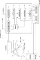
図1には、本実施形態に係る手術用ロボットの制御システムの概略構成図が示されている。この図において、制御システム10は、マスタースレーブ方式の手術支援ロボットに対する動作制御を行うためのシステムであって、対象者となる患者Pの体内器官の一部である臓器Lを撮像可能な撮像装置11と、臓器Lに対して所定の処置を施すためのロボット本体12と、このロボット本体12を操作する操作装置13と、操作装置13からの操作指令に基づいてロボット本体12の動作を制御する制御装置14と、モデル化された患者Pの臓器Lから、当該臓器Lに外力が付与されたときの臓器Lの各部分の状態をシミュレーションするシミュレーション装置16とを備えて構成されている。
FIG. 1 shows a schematic configuration diagram of a control system for a surgical robot according to the present embodiment. In this figure, a control system 10 is a system for performing operation control on a master-slave type surgery support robot, and is an imaging device capable of imaging an organ L that is a part of a body organ of a patient P as a subject. 11, a robot
前記撮像装置11は、手術前や手術時に患者の臓器Lを撮像可能な装置であれば何でも良く、例えば、磁気画像共鳴診断装置(MRI)、コンピュータ断層撮影装置(CTスキャン)、超音波画像診断装置等、公知の装置を適用可能である。また、後述する処理に必要な臓器Lの部分を撮像可能であれば、撮像装置11として、腹腔鏡下手術等の際に体内に挿入される内視鏡を用いてもよい。 The imaging device 11 may be any device as long as it can image a patient's organ L before or during an operation. For example, a magnetic image resonance diagnostic device (MRI), a computed tomography device (CT scan), or an ultrasonic image diagnosis. A known device such as a device can be applied. In addition, an endoscope that is inserted into the body during laparoscopic surgery or the like may be used as the imaging device 11 as long as the part of the organ L necessary for processing to be described later can be imaged.
前記ロボット本体12は、臓器Lの処置を行う鉗子等の処置具を保持するマニピュレータ23と、このマニピュレータ23の基部側を保持して、当該マニピュレータ23を移動可能に動作するロボットアーム24と、このロボットアーム24を駆動させる図示しないモータを含む駆動装置25とを備えている。
The
前記マニピュレータ23は、患者Pの体内外を貫通するように配置された筒状のトロカールT内に挿通されており、先端側には、臓器Lに付加した力に対する反力を検出可能な力センサ27が取り付けられている。 The manipulator 23 is inserted into a cylindrical trocar T that is arranged so as to penetrate the inside and outside of the patient P, and a force sensor capable of detecting a reaction force against the force applied to the organ L at the distal end side. 27 is attached.
前記ロボットアーム24及び駆動装置25は、公知の手術支援ロボットに適用される構造が採用されており、本発明の要旨ではないため、ここでは詳細な説明を省略する。
The
前記操作装置13は、いわゆるマスターマニピュレータと称される装置であって、術者が図示しないモニタに表示される臓器Lの画像を見ながら、図示しない操作部を医師が把持して所望の方向に動かすことで、ロボットアーム24を所望の方向に操作可能となる公知の構造のものが採用されている。本構造についても、本発明の要旨ではないため、ここでは詳細な説明を省略する。
The
前記制御装置14は、所定のコンピュータからなり、当該コンピュータを以下の各部として機能させるプログラムがインストールされている。すなわち、制御装置14は、術者による操作装置13の操作に対応したマニピュレータ23の所望動作が得られるようにするための主制御部29と、マニピュレータ23の動作によって臓器Lに外力が付加されたときに、前記シミュレーション装置16でシミュレーションされた臓器Lの各部分の状態に基づいて、マニピュレータ23の動作を変更するための変更制御部30とを備えている。
The control device 14 includes a predetermined computer, and a program for causing the computer to function as the following units is installed. That is, the control device 14 applies an external force to the organ L by the
前記シミュレーション装置16は、所定のコンピュータからなり、当該コンピュータを以下の手段として機能させるプログラムがインストールされている。このシミュレーション装置16は、撮像装置11からの画像データに基づいて患者Pの臓器Lをモデル化し、このモデルを使って、臓器Lに外力が付加されたときの当該臓器Lの各部分の応力状態や変形状態を推定する状態推定手段31を含んで構成されている。 The simulation apparatus 16 is composed of a predetermined computer, and a program for causing the computer to function as the following means is installed. The simulation device 16 models the organ L of the patient P based on the image data from the imaging device 11, and using this model, the stress state of each part of the organ L when an external force is applied to the organ L. And state estimation means 31 for estimating the deformation state.
前記状態推定手段31は、予め指定された臓器Lの弾性率やポアソン比等の材料パラメータからなる基礎データ及び生体組織が破壊に至る応力を表す破壊応力データ等が記憶された記憶部33と、マニピュレータ23によって患者Pの臓器Lに外力が付加される前に撮像装置11で撮像した画像データに基づき、臓器Lの形状及びその各構成組織の位置を求める形状位置特定部34と、形状位置特定部34で求められた臓器Lの形状に基づいて臓器Lを複数の要素に分割する要素分割部35と、記憶部33で記憶された前記基礎データに基づいて前記外力と変位の関係を要素毎に求め、臓器Lに対する外力ベクトルと当該臓器Lの変位ベクトルとの関係を表す剛体方程式を有限要素法で求める剛体方程式決定部36と、剛体方程式を使い、力センサ27で検出された前記外力の大きさから前記各要素に作用する応力(状態量)を求める状態量算出部37と、状態量算出部37で求められた応力について、記憶部33で記憶された前記破壊応力データに関連して設定された所定の閾値を超えているか否かを判定することで、構成組織の損傷の可能性があるか否かを判定する状態判定部38と、状態判定部38での判定に応じて、前記変更制御部30への指令を行う変更指令部39とを備えている。
The state estimation means 31 includes a
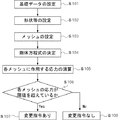
次に、本実施形態のシミュレーション装置16で行われる処理について、図2のフローチャートを用いながら以下に説明する。なお、以下においては、処理対象となる臓器Lを例示的に肝臓として説明するが、これに限定されるものではない。 Next, processing performed by the simulation apparatus 16 of the present embodiment will be described below with reference to the flowchart of FIG. In the following, the organ L to be processed will be described as an example of the liver, but the present invention is not limited to this.
予め、学術的に解明されている一般的なヒトの肝臓Lの弾性率及びポアソン比の基礎データが、肝臓Lの部分すなわち構成組織毎に記憶部33に入力されて記憶される(ステップS101)。すなわち、ここでは、肝細胞(肝実質細胞)、血管、神経等の肝臓Lの構成組織毎に基礎データが設定される。ここで、血管、神経等の組織は、過負荷を掛けることのできない注意部位となる。また、記憶部33には、生体組織が破壊に至る応力を表す破壊応力データとして、学術的に解明されている値が前記構成組織毎に記憶される。なお、弾性率測定装置としての公知のエラストグラフィー装置(図示省略)で測定した患者Pの肝臓Lの弾性率を記憶部33に記憶させることもできる。このエラストグラフィー装置は、体表側から肝臓Lに外力を付加しながら超音波を当て、その反射波の位相のずれを利用して弾性率を決定する装置であるが、本装置の構成は、本発明の要旨ではないため、詳細な説明を省略する。
Basic data on the elastic modulus and Poisson's ratio of a general human liver L that has been scientifically elucidated in advance is input and stored in the
そして、患者Pの肝臓Lが撮像装置11で撮像され、形状位置特定部34で、患者Pの肝臓Lの形状と当該肝臓Lの各構成組織の位置とが次のようにして設定される(ステップS102)。すなわち、撮像装置11で手術前に撮像された画像データに基づいて、コンピュータを使った公知の画像処理により、肝臓Lの三次元形状若しくは所定断面の二次元形状が導出され、且つ、その中の構成組織(肝実質細胞、血管、神経等)の位置が特定される。なお、肝臓Lの形状及び各構成組織の位置は、前記形状位置特定部34の自動処理でなく、前記画像データを視認した人間による手入力で設定してもよい。
Then, the liver L of the patient P is imaged by the imaging device 11, and the shape
次に、要素分割部35で、形状位置特定部34で求めた肝臓Lの形状に基づき、有限要素法における要素(メッシュM)の形状と、当該各メッシュMの節点(ノードN)の数とを指定することで、公知の演算処理により、図3に示されるように、肝臓L全体を複数分割した各メッシュMが設定される(ステップS103)。なお、図3においては、図面の錯綜を回避するため、肝臓Lの一部領域のみメッシュMを記載し、残りの領域におけるメッシュMの記載は省略している。
Next, in the element dividing unit 35, based on the shape of the liver L obtained by the shape
その後、剛体方程式決定部36で、次のように、有限要素法を使って剛体方程式が決定される(ステップS104)。すなわち、先ず、形状位置特定部34で求められた肝臓Lの各構成組織の位置と、要素分割部35で決定された各メッシュMとを対比することにより、各メッシュMは、肝臓Lのどの構成組織に該当するのかが特定される。そして、各メッシュMそれぞれに対して、記憶部33で構成組織毎に記憶された肝臓Lの弾性率及びポアソン比のうち、該当する組織のものを選択し、構造計算によって、メッシュMの周囲のノードNにかかる荷重と当該メッシュMの変形情報との関係式が求められる。ここでの変形情報は、対象となるメッシュMを構成するノードNの変位と、当該メッシュM内に作用する応力及びひずみを指す。そして、前記関係式から肝臓L全体の剛性方程式が求められる。ここで、剛性方程式は、各ノードNに作用する外力ベクトルFとし、全体の剛性マトリックスKとし、ノードNの変位ベクトルUとすると、次式(1)のように表される。

その後、状態量算出部37では、マニピュレータ23による肝臓Lの処置時に、当該肝臓Lの各メッシュMに作用している応力が次のようにして演算される(ステップS105)。すなわち、先ず、マニピュレータ23の先端側の力センサ27で検出された反力をマニピュレータ23が肝臓に付加した外力として考え、制御装置14からの情報により得られたマニピュレータ23の先端位置を考慮して、前記外力の作用している肝臓Lの位置と、この外力の方向及び大きさが求められる。これによって、各ノードNに作用する外力ベクトルFが求められ、上式(1)の関係により、剛性マトリックスKの逆行列からノードNの変位ベクトルUが求められる。このように各ノードNの変位が求まると、記憶部33で記憶された該当する構成組織の弾性率及びポアソン比を使った構造計算によって、各メッシュMのミーゼス応力が求められる。なお、ここで求める応力としては、ミーゼス応力に限定されるものではなく、他の応力でもよい。
Thereafter, in the state
次に、状態判定部38では、状態量算出部37で求められた各メッシュMの応力が、記憶部33に記憶された構成組織毎の破壊応力データに基づく閾値を超えているか否かが判定される(ステップS106)。ここでの閾値は、特に限定されるものではないが、構成組織の破壊応力に対して同程度若しくはやや小さい程度に設定されている。なお、状態判定部38では、状態量算出部37で求められた各メッシュMの応力のうち、予め設定された血管、神経等の注意部位に位置するメッシュMに関する応力のみを判定してもよい。要するに、状態判定部38での構成組織の損傷の可能性があるか否かの判定は、対象となる臓器Lに応じてメッシュMを適宜選択し、又は、メッシュMの全部について行ってもよい。
Next, the
このとき、各メッシュMの応力のうち少なくとも一つが、前記閾値を超えている場合には、変更指令部39で、現在の応力状態が更に増大しないようなマニピュレータ23の動作の変更指令が前記変更制御部30になされ(ステップS107)、当該変更制御部30によりマニピュレータ23の動作制御が行われる。一方、各メッシュMの応力が、前記閾値を超えていない場合には、変更指令部39での変更指令が行われず(ステップS108)、操作装置13の操作指令に応じた主制御部29によるマニピュレータ23の動作制御が行われる。
At this time, if at least one of the stresses of each mesh M exceeds the threshold value, the
従って、このような第1実施形態によれば、低侵襲手術時において、マニピュレータ23を使って肝臓Lの手術を行っている際に、患者の肝臓Lを想定したモデルを使って、肝臓L内において過負荷を掛けることのできない注意部位である血管部分や神経部分に作用している応力を推定することができ、肝臓Lに作用する応力を手術中の実際の肝臓Lから調べずに、注意部位に対する不意の損傷等の防止効果を高めることができる。 Therefore, according to the first embodiment as described above, during the operation of the liver L using the manipulator 23 during the minimally invasive surgery, the model in the liver L is used by using the model assuming the liver L of the patient. In this case, it is possible to estimate the stress acting on the vascular part or nerve part, which is a caution part that cannot be overloaded, so that the stress acting on the liver L is not examined from the actual liver L during the operation. The effect of preventing unexpected damage to the site can be enhanced.
なお、前記状態推定手段31は、患者Pの臓器Lの画像データに基づいて当該臓器Lをモデル化し、このモデルを使って、臓器Lに外力が付加されたときのその各部分の応力状態及び/又は変形状態を推定できる限り、本実施形態の構成要素の一部を省略し、前述したように、その省略部分を人間によるデータ設定等に代替することもできる。 The state estimating means 31 models the organ L based on the image data of the organ L of the patient P, and using this model, the stress state of each part when an external force is applied to the organ L and As long as the deformation state can be estimated, a part of the constituent elements of the present embodiment may be omitted, and as described above, the omitted part may be replaced with human data setting or the like.
次に、本発明の他の実施形態について説明する。なお、以下の説明において、前記第1実施形態と同一若しくは同等の構成部分及び処理内容については同一符号を用いるものとし、説明を省略若しくは簡略にする。
(第2実施形態)
Next, another embodiment of the present invention will be described. In the following description, the same reference numerals are used for the same or equivalent components and processing contents as in the first embodiment, and the description will be omitted or simplified.
(Second Embodiment)
本実施形態のシミュレーション装置42は、第1実施形態のシミュレーション装置16に対し、図4に示されるように、前記状態推定手段31で用いられる弾性率及びポアソン比からなる基礎データを実際の患者Pの肝臓Lの状態に合わせて補正する定数補正手段44を更に追加したところに特徴を有する。なお、本実施形態においても、処理対象となる臓器Lを肝臓として説明するが、これに限定されるものではない。 As shown in FIG. 4, the simulation device 42 of the present embodiment provides basic data including the elastic modulus and Poisson's ratio used in the state estimation means 31 to the actual patient P, as shown in FIG. 4. It is characterized in that a constant correction means 44 for correcting according to the state of the liver L is further added. In the present embodiment, the organ L to be processed is described as a liver, but the present invention is not limited to this.
記憶部33に予め記憶された初期の基礎データは、一般的なヒトの肝臓Lに関するものであり、詳細な値は、各患者Pの病態や個人差等によって相違している。また、前記エラストグラフィー装置(図示省略)を利用して初期の基礎データを設定した場合でも、肝臓Lの各構成組織の弾性率を詳しく測定するのには限界がある。そこで、本実施形態のシミュレーション装置42は、マニピュレータ23の動作中における肝臓Lの変形状態から基礎データを患者固有の値に補正し、当該補正した基礎データを使って第1実施形態で述べた処理を行うようになっている。
The initial basic data stored in advance in the
前記定数補正手段44は、肝臓Lに外力が付加されている手術中の患者Pの画像データに基づき、拡張カルマンフィルタを用いて記憶部33に記憶された弾性率及びポアソン比を補正するようになっている。つまり、外力が付加された状態の肝臓Lの変形は、同じ外力の状態でも、肝臓の弾性率及びポアソン比によって状態が変わることに着目し、定数補正手段44では、患者の肝臓Lを経時的に撮像した画像データから肝臓の状態を確認し、当該状態に基づいて実際の患者Pの弾性率及びポアソン比を修正するようになっている。
The constant correction means 44 corrects the elastic modulus and Poisson's ratio stored in the
なお、定数補正手段44は、前記状態推定手段31とともにシミュレーション装置42内に設けられているが、状態推定手段31と別の装置構成にすることもできる。また、本実施形態では、拡張カルマンフィルタを使って弾性率及びポアソン比が補正されるが、以下の処理で同様に弾性率及びポアソン比を補正できる限り、最小二乗法等の他のパラメータ同定法を使うこともできる。 The constant correction unit 44 is provided in the simulation apparatus 42 together with the state estimation unit 31, but may be configured differently from the state estimation unit 31. In this embodiment, the elastic modulus and Poisson's ratio are corrected using the extended Kalman filter. However, as long as the elastic modulus and Poisson's ratio can be corrected similarly in the following processing, other parameter identification methods such as the least squares method are used. It can also be used.
次に、第2実施形態の状態推定手段42で行われる処理について、図5のフローチャートを用いながら以下に説明する。 Next, processing performed by the state estimation unit 42 of the second embodiment will be described below using the flowchart of FIG.
本実施形態では、先ず、第1実施形態のステップS101と同様に、ヒトの肝臓Lの弾性率、ポアソン比からなる基礎データが、肝臓Lの構成組織毎に設定されて記憶部33に入力される(ステップS201)。
In the present embodiment, first, as in step S101 of the first embodiment, basic data including the elastic modulus and Poisson's ratio of the human liver L is set for each constituent tissue of the liver L and input to the
そして、第1実施形態のステップS102と同様に、患者の肝臓Lが撮像装置11で撮像され、形状位置特定部34で患者Pの肝臓Lの形状と当該肝臓Lの各構成組織の位置とが設定される(ステップS202)。
Similarly to step S102 of the first embodiment, the liver L of the patient is imaged by the imaging device 11, and the shape
次に、第1実施形態のステップS103と同様に、要素分割部35で、形状位置特定部11で求められた肝臓Lの形状に基づき、肝臓Lを複数分割して得られる各メッシュMが設定される(ステップS203)。 Next, as in step S103 of the first embodiment, the element division unit 35 sets each mesh M obtained by dividing the liver L into a plurality of parts based on the shape of the liver L obtained by the shape position specifying unit 11. (Step S203).
そして、第1実施形態のステップS104と同様に、剛体方程式決定部36で、記憶部33に記憶された弾性率及びポアソン比を使って、最初の剛体方程式が決定される(ステップS204)。 Then, similarly to step S104 of the first embodiment, the rigid body equation determination unit 36 determines the first rigid body equation using the elastic modulus and Poisson's ratio stored in the storage unit 33 (step S204).
その後、第1実施形態のステップS105と同様に、状態量算出部37で、力センサ34による検出値から、各ノードNに作用する外力ベクトルFが求められ、更に、ステップS204で決定した剛体方程式を使って、ノードの変位ベクトルUAが求められ(ステップS205)、各メッシュMに作用している応力が算出される(ステップS206)。
After that, as in step S105 of the first embodiment, the state
そして、定数補正手段44で、撮像装置11で撮像された所定時間t及びその前の時間t−1における肝臓Lの各画像データから、公知の画像マッチング等の画像処理を使い、各画像データ間における各ノードNの位置の相違から、各ノードNの変位量を求め、これら変位量からノードNの変位ベクトルUBが求められる(ステップS207)。 Then, the constant correction means 44 uses the image processing such as known image matching from each image data of the liver L at the predetermined time t and the previous time t−1 captured by the imaging device 11, between each image data. from the difference in position of each node N in, determine the amount of displacement of each node N, the displacement vector U B of the node N from these displacement determined (step S207).
更に、定数補正手段44で、記憶部33に記憶された弾性率及びポアソン比に基づいてステップS205で求めたノードNの変位ベクトルUAと、実際の画像データ上の肝臓の変形に基づいてステップS207で求めたノードNの変位ベクトルUBとの差を解消するように、カルマンゲインをKtとした次式の拡張カルマンフィルタによって、各メッシュMに対する新たな弾性率及びポアソン比が算出される(ステップS208)。
また、ステップS205で変位ベクトルUAを求める度に、そのときの弾性率及びポアソン比を使ってステップS206で求めた各メッシュMに作用する応力につき、状態判定部38及び変更指令部39にて、第1実施形態のステップS106〜ステップS108の各処理と同様の処理が行われる。すなわち、ステップS206で求めた各メッシュMの応力が構成組織の損傷の指標となる閾値を超えているか否かが判定され(ステップS210)、所定のメッシュMの応力が閾値を超えている場合には、その状態を進行させないように変更制御部30に対する変更指令が行われる一方(ステップS211)、そうでない場合は、変更制御部30に対する変更指令が行われない(ステップS212)。
Also, every time obtaining a displacement vector U A at step S205, every stress acting on each mesh M obtained in step S206 by using the elastic modulus and Poisson's ratio at that time, in the
従って、このような第2実施形態によれば、特有のセンサや機器を別途設けることなく、手術時における臓器Lの変形から、予め設定した臓器Lの弾性率及びポアソン比を実際の患者のものに適宜修正することができる。そして、弾性率及びポアソン比を修正しながら、状態量算出部37で応力を再計算するため、各メッシュMに作用する応力の正確性が経時的に増すことになる。
Therefore, according to the second embodiment as described above, the elasticity and Poisson's ratio of the organ L set in advance from the deformation of the organ L at the time of surgery can be obtained from an actual patient without separately providing a special sensor or device. It can be modified as appropriate. Since the state
なお、以上の各実施形態の状態推定手段31では、撮像装置11により画像データを経時的に取得してこれら画像の変化から各ノードNの変位を求め、ノードNの変位ベクトルUから、剛性方程式を使って各ノードNに作用する外力ベクトルFを求め、これら外力ベクトルFから各メッシュに作用する応力を求めてもよい。このようにすれば、力センサ27を省略することもできる。
In the state estimation means 31 of each of the above embodiments, image data is acquired over time by the imaging device 11, the displacement of each node N is obtained from the change in these images, and the stiffness equation is obtained from the displacement vector U of the node N. May be used to determine the external force vector F acting on each node N, and the stress acting on each mesh may be determined from these external force vectors F. In this way, the
また、力センサ27は、マニピュレータ23の先端側に設けられていなくてもよく、マニピュレータ23で臓器Lに付与した外力の大きさを検出できる限りにおいて、その設置位置は特に問わず、体外側に設けられていてもよい。
Further, the
更に、変更指令部39からの指令によって、変更制御部30での前述の制御の代わりに若しくは当該制御とともに、次のように構成することもできる。すなわち、各メッシュMの応力が予め設定された閾値を超えている場合に、臓器Lの注意部位等に過負荷が掛かっていることを所定の機器や機構を通じて術者に伝達する構成としてもよい。例えば、変更指令部39からの指令により、前記操作装置13の操作を不能に若しくは操作を制限するようにロックしたり、図示しないスピーカー等から警告音を発したり、図示しないモニタで警告表示するようにしてもよい。
Further, in accordance with a command from the
また、各実施形態のシミュレーション装置16,42は、手術支援ロボットとの併用が必須ではなく、当該ロボットを使わずに医師等の直接の術具操作にて行う手術において、当該術具の一部に設けた力センサ及び位置センサの検出値により、状態推定手段31で手術中の臓器L内の応力状態等を求め、前述のように警告音やモニタでの表示等を通じて術者に警告状態を伝達することも可能である。 In addition, the simulation devices 16 and 42 of each embodiment are not necessarily used in combination with a surgery support robot, and a part of the surgery tool is used in a surgery performed by a doctor or the like directly using a surgery tool without using the robot. Based on the detection values of the force sensor and the position sensor provided in the above, the state estimation means 31 obtains the stress state in the organ L during the operation, and the warning state is displayed to the operator through the warning sound and the display on the monitor as described above. It is also possible to communicate.
更に、前記各実施形態では、対象となる器官の性状を示す材料パラメータとして、弾性率及びポアソン比を用いたが、密度や粘性等、その他の材料パラメータを使って前述した各種処理を行うこともできる。 Furthermore, in each of the above embodiments, the elastic modulus and Poisson's ratio are used as material parameters indicating the properties of the target organ. However, the various processes described above may be performed using other material parameters such as density and viscosity. it can.
その他、本発明における装置各部の構成及び処理手順は前述した実施形態の態様に限定されるものではなく、実質的に同様の作用を奏する限りにおいて、種々の変更が可能である。 In addition, the configuration and processing procedure of each part of the apparatus according to the present invention are not limited to the aspect of the above-described embodiment, and various modifications are possible as long as substantially the same operation is achieved.
10 制御システム
11 撮像装置
14 制御装置
16 シミュレーション装置
23 マニピュレータ
25 駆動装置
31 状態推定手段
34 形状位置特定部
35 要素分割部
36 剛体方程式決定部
37 状態量算出部
38 状態判定部
42 シミュレーション装置
44 定数補正手段
F 外力ベクトル
L 臓器(器官)
M メッシュ
N ノード
P 患者(対象者)
U 変位ベクトル
DESCRIPTION OF SYMBOLS 10 Control system 11 Imaging apparatus 14 Control apparatus 16 Simulation apparatus 23
M mesh N node P Patient (subject)
U displacement vector
Claims (6)
前記状態推定手段は、弾性率やポアソン比を含む材料パラメータからなる基礎データ及び生体組織が破壊に至る応力を表す破壊応力データが、前記器官の構成部分となる構成組織それぞれについて記憶された記憶部と、前記外力の付加前に撮像された前記画像データに基づいて前記器官の形状及び前記各構成組織の位置を求める形状位置特定部と、当該形状位置特定部で求められた前記器官の形状に基づいて前記器官を複数のメッシュに分割する要素分割部と、前記記憶部で記憶された前記基礎データに基づいて、前記外力と変位との関係を前記メッシュ毎に求め、前記器官に対する外力ベクトルと当該器官の変位ベクトルの関係を表す剛体方程式を有限要素法で求める剛体方程式決定部と、前記外力ベクトルを前記剛体方程式に代入して前記変位ベクトルを求め、この変位ベクトルから、前記材料パラメータを使って、前記各メッシュに作用する応力を求める状態量算出部と、当該状態量算出部で求められた前記各メッシュの応力について、前記記憶部で記憶された前記破壊応力データに関連して前記メッシュ毎に設定された所定の閾値を超えているか否かを判定することにより、前記構成組織の損傷の可能性があるか否かを判定する状態判定部とを備えたことを特徴とするシミュレーション装置。 Modeling the organs based on the image data of the organ of the subject, using this model, with a state estimation means for estimating the stress state of each part of the organ when the external force is added to the organ A simulation device,
The state estimation means is a storage unit in which basic data consisting of material parameters including elastic modulus and Poisson's ratio and fracture stress data representing stress that causes the biological tissue to break are stored for each of the constituent tissues that are constituent parts of the organ And a shape position specifying unit for obtaining the shape of the organ and the position of each constituent tissue based on the image data imaged before the external force is applied, and the shape of the organ obtained by the shape position specifying unit. An element dividing unit that divides the organ into a plurality of meshes based on the basic data stored in the storage unit, the relationship between the external force and displacement is determined for each mesh, an external force vector for the organ, A rigid body equation determination unit that obtains a rigid body equation representing the relationship between the displacement vectors of the organ by a finite element method, and the external force vector is substituted into the rigid body equation before A displacement vector is obtained, and from this displacement vector, using the material parameters, a state quantity calculation unit for obtaining a stress acting on each mesh, and the stress of each mesh obtained by the state quantity calculation unit are stored in the memory. It is determined whether there is a possibility of damage of the constituent tissue by determining whether or not a predetermined threshold set for each mesh is exceeded in relation to the fracture stress data stored in the section A simulation apparatus comprising: a state determination unit that performs the operation .
前記定数補正手段は、前記材料パラメータに基づき前記状態量算出部で求めた少なくとも一部のメッシュの変位ベクトルと、当該メッシュについて前記外力が付加されているときの前記画像データの変化から求めた変位ベクトルとの差を解消するように前記材料パラメータを補正し、
前記剛体方程式決定部及び前記状態量算出部では、前記定数補正手段で求められた前記材料パラメータが使われることを特徴とする請求項1記載のシミュレーション装置。 Based on image data of the subject when an external force is applied to the organ, further comprising constant correction means for correcting the material parameter using a parameter identification method,
The constant correction means is a displacement vector obtained from a change vector of at least a part of the mesh obtained by the state quantity calculation unit based on the material parameter and a change in the image data when the external force is applied to the mesh. Correct the material parameters to eliminate the difference with the vector,
Wherein the rigid equation determining unit and the state quantity calculating section, a simulation apparatus according to claim 1, characterized in that the material parameters determined by the constant compensation unit is used.
前記シミュレーション装置は、対象者の器官の画像データに基づいて当該器官をモデル化し、このモデルを使って、前記器官に外力が付加されたときの当該器官の各部分の応力状態を推定する状態推定手段を備え、
前記状態推定手段は、弾性率やポアソン比を含む材料パラメータからなる基礎データ及び生体組織が破壊に至る応力を表す破壊応力データが、前記器官の構成部分となる構成組織それぞれについて記憶された記憶部と、前記外力の付加前に撮像された前記画像データに基づいて前記器官の形状及び前記各構成組織の位置を求める形状位置特定部と、当該形状位置特定部で求められた前記器官の形状に基づいて前記器官を複数のメッシュに分割する要素分割部と、前記記憶部で記憶された前記基礎データに基づいて、前記外力と変位との関係を前記メッシュ毎に求め、前記器官に対する外力ベクトルと当該器官の変位ベクトルの関係を表す剛体方程式を有限要素法で求める剛体方程式決定部と、前記外力ベクトルを前記剛体方程式に代入して前記変位ベクトルを求め、この変位ベクトルから、前記材料パラメータを使って、前記各メッシュに作用する応力を求める状態量算出部と、当該状態量算出部で求められた前記各メッシュの応力について、前記記憶部で記憶された前記破壊応力データに関連して前記メッシュ毎に設定された所定の閾値を超えているか否かを判定することにより、前記構成組織の損傷の可能性があるか否かを判定する状態判定部とを備えたことを特徴とする手術用ロボットの制御システム。 An imaging device that images a patient's organ, a manipulator inserted into the patient's body, a driving device that operates the manipulator, and the organ is modeled based on image data of the patient's organ, and the model is used. And controlling a driving device for driving the manipulator based on a predetermined operation command and an estimation result by the simulation device, and estimating a state of each part of the organ when an external force is applied to the organ. And a control device that
The simulation apparatus models the organ based on the image data of the organ of the subject, and uses this model to estimate the stress state of each part of the organ when an external force is applied to the organ With means,
The state estimation means is a storage unit in which basic data consisting of material parameters including elastic modulus and Poisson's ratio and fracture stress data representing stress that causes the biological tissue to break are stored for each of the constituent tissues that are constituent parts of the organ And a shape position specifying unit for obtaining the shape of the organ and the position of each constituent tissue based on the image data imaged before the external force is applied, and the shape of the organ obtained by the shape position specifying unit. An element dividing unit that divides the organ into a plurality of meshes based on the basic data stored in the storage unit, the relationship between the external force and displacement is determined for each mesh, an external force vector for the organ, A rigid body equation determination unit that obtains a rigid body equation representing the relationship between the displacement vectors of the organ by a finite element method, and the external force vector is substituted into the rigid body equation before A displacement vector is obtained, and from this displacement vector, using the material parameters, a state quantity calculation unit for obtaining a stress acting on each mesh, and the stress of each mesh obtained by the state quantity calculation unit are stored in the memory. It is determined whether there is a possibility of damage of the constituent tissue by determining whether or not a predetermined threshold set for each mesh is exceeded in relation to the fracture stress data stored in the section A surgical robot control system comprising: a state determination unit that performs the operation.
前記シミュレーション装置は、前記弾性率測定装置で測定された弾性率を使って、前記器官の各部分の応力状態及び/又は変形状態を推定することを特徴とする請求項3記載の手術用ロボットの制御システム。 An elastic modulus measuring device capable of measuring the elastic modulus of each part of the organ from the outside of the body;
4. The surgical robot according to claim 3 , wherein the simulation apparatus estimates a stress state and / or a deformation state of each part of the organ using the elastic modulus measured by the elastic modulus measuring apparatus. Control system.
弾性率やポアソン比を含む材料パラメータからなる基礎データ及び生体組織が破壊に至る応力を表す破壊応力データが、前記器官の構成部分となる構成組織それぞれについて記憶された記憶部と、前記外力の付加前に撮像された前記画像データに基づいて前記器官の形状及び前記各構成組織の位置を求める形状位置特定部と、当該形状位置特定部で求められた前記器官の形状に基づいて前記器官を複数のメッシュに分割する要素分割部と、前記記憶部で記憶された前記基礎データに基づいて、前記外力と変位との関係を前記メッシュ毎に求め、前記器官に対する外力ベクトルと当該器官の変位ベクトルの関係を表す剛体方程式を有限要素法で求める剛体方程式決定部と、前記外力ベクトルを前記剛体方程式に代入して前記変位ベクトルを求め、この変位ベクトルから、前記材料パラメータを使って、前記各メッシュに作用する応力を求める状態量算出部と、当該状態量算出部で求められた前記各メッシュの応力について、前記記憶部で記憶された前記破壊応力データに関連して前記メッシュ毎に設定された所定の閾値を超えているか否かを判定することにより、前記構成組織の損傷の可能性があるか否かを判定する状態判定部として、前記シミュレーション装置のコンピュータを機能させることを特徴とするシミュレーション装置用のプログラム。 Modeling the organs based on the image data of the organ of the subject, using this model, in the organs of a program for simulation apparatus for estimating the stress state of each part when an external force is added to the organ There,
A storage unit in which basic data composed of material parameters including elastic modulus and Poisson's ratio, and fracture stress data representing stress leading to the destruction of living tissue are stored for each component tissue constituting the organ, and addition of the external force A shape position specifying unit that obtains the shape of the organ and the position of each constituent tissue based on the image data that has been previously imaged, and a plurality of the organs that are based on the shape of the organ obtained by the shape position specifying unit. Based on the basic data stored in the storage unit and an element dividing unit that divides the mesh, a relationship between the external force and displacement is obtained for each mesh, and an external force vector for the organ and a displacement vector of the organ A rigid body equation determination unit that obtains a rigid body equation representing a relationship by a finite element method, and obtains the displacement vector by substituting the external force vector into the rigid body equation. From this displacement vector, using the material parameters, the state quantity calculation unit for obtaining the stress acting on each mesh, and the stress of each mesh obtained by the state quantity calculation unit are stored in the storage unit. As a state determination unit that determines whether or not there is a possibility of damage to the constituent tissue by determining whether or not a predetermined threshold set for each mesh is exceeded in relation to the fracture stress data A program for a simulation apparatus that causes a computer of the simulation apparatus to function .
前記定数補正手段は、前記材料パラメータに基づき前記状態量算出部で求めた少なくとも一部のメッシュの変位ベクトルと、当該メッシュについて前記外力が付加されているときの前記画像データの変化から求めた変位ベクトルとの差を解消するように前記材料パラメータを補正し、
前記剛体方程式決定部及び前記状態量算出部では、前記定数補正手段で求められた前記材料パラメータが使われることを特徴とする請求項5記載のシミュレーション装置用のプログラム。 Based on the image data of the subject when an external force is applied to the organ, the computer further functions as a constant correction unit that corrects the material parameter using a parameter identification method,
The constant correction means is a displacement vector obtained from a change vector of at least a part of the mesh obtained by the state quantity calculation unit based on the material parameter and a change in the image data when the external force is applied to the mesh. Correct the material parameters to eliminate the difference with the vector,
6. The program for a simulation apparatus according to claim 5, wherein the rigid body equation determination unit and the state quantity calculation unit use the material parameter obtained by the constant correction unit .
Priority Applications (1)
| Application Number | Priority Date | Filing Date | Title |
|---|---|---|---|
| JP2006266103A JP4636618B2 (en) | 2006-09-28 | 2006-09-28 | Simulation device, surgical robot control system using the same, and program for simulation device |
Applications Claiming Priority (1)
| Application Number | Priority Date | Filing Date | Title |
|---|---|---|---|
| JP2006266103A JP4636618B2 (en) | 2006-09-28 | 2006-09-28 | Simulation device, surgical robot control system using the same, and program for simulation device |
Publications (2)
| Publication Number | Publication Date |
|---|---|
| JP2008080021A JP2008080021A (en) | 2008-04-10 |
| JP4636618B2 true JP4636618B2 (en) | 2011-02-23 |
Family
ID=39351458
Family Applications (1)
| Application Number | Title | Priority Date | Filing Date |
|---|---|---|---|
| JP2006266103A Expired - Fee Related JP4636618B2 (en) | 2006-09-28 | 2006-09-28 | Simulation device, surgical robot control system using the same, and program for simulation device |
Country Status (1)
| Country | Link |
|---|---|
| JP (1) | JP4636618B2 (en) |
Families Citing this family (9)
| Publication number | Priority date | Publication date | Assignee | Title |
|---|---|---|---|---|
| JP4991391B2 (en) * | 2007-05-22 | 2012-08-01 | 三菱プレシジョン株式会社 | Surgical cutting motion simulation method and apparatus |
| JP5215828B2 (en) * | 2008-12-02 | 2013-06-19 | 三菱プレシジョン株式会社 | Model generation method for preoperative simulation |
| JP5392770B2 (en) * | 2009-12-16 | 2014-01-22 | 独立行政法人産業技術総合研究所 | Needle-like surgical instrument insertion support device |
| EP2526525B1 (en) * | 2010-01-22 | 2016-05-04 | Vanderbilt University | System and method for correcting data for deformations during image-guided procedures |
| US11564768B2 (en) * | 2017-03-31 | 2023-01-31 | Koninklijke Philips N.V. | Force sensed surface scanning systems, devices, controllers and method |
| WO2019187025A1 (en) * | 2018-03-30 | 2019-10-03 | オリンパス株式会社 | Stress estimation system, stress estimation device, and endoscope system |
| JP7188970B2 (en) * | 2018-10-11 | 2022-12-13 | ザイオソフト株式会社 | ROBOT SURGERY ASSISTANCE DEVICE, OPERATION METHOD OF ROBOT SURGERY ASSISTANCE DEVICE, AND PROGRAM |
| JP2021153773A (en) * | 2020-03-26 | 2021-10-07 | 株式会社メディカロイド | Robot surgery support device, surgery support robot, robot surgery support method, and program |
| AU2023230574A1 (en) * | 2022-03-08 | 2024-08-08 | Sony Group Corporation | Simulation system, information processing device, and information processing method |
Citations (2)
| Publication number | Priority date | Publication date | Assignee | Title |
|---|---|---|---|---|
| JP2004344491A (en) * | 2003-05-23 | 2004-12-09 | Hideo Fujimoto | Virtual surgery simulation system |
| JP2005278992A (en) * | 2004-03-30 | 2005-10-13 | Hamamatsu Univ School Of Medicine | Apparatus, method and program for supporting surgery |
-
2006
- 2006-09-28 JP JP2006266103A patent/JP4636618B2/en not_active Expired - Fee Related
Patent Citations (2)
| Publication number | Priority date | Publication date | Assignee | Title |
|---|---|---|---|---|
| JP2004344491A (en) * | 2003-05-23 | 2004-12-09 | Hideo Fujimoto | Virtual surgery simulation system |
| JP2005278992A (en) * | 2004-03-30 | 2005-10-13 | Hamamatsu Univ School Of Medicine | Apparatus, method and program for supporting surgery |
Also Published As
| Publication number | Publication date |
|---|---|
| JP2008080021A (en) | 2008-04-10 |
Similar Documents
| Publication | Publication Date | Title |
|---|---|---|
| JP4636618B2 (en) | Simulation device, surgical robot control system using the same, and program for simulation device | |
| JP7515495B2 (en) | Collecting training data for machine learning models | |
| JP5288447B2 (en) | Surgery support system, approach state detection device and program thereof | |
| JP4390146B2 (en) | Puncture control device, puncture robot, and puncture control program | |
| CN107847274B (en) | Method and apparatus for providing updated patient images during robotic surgery | |
| EP3603558B1 (en) | Global mapping catheter contact optimization | |
| CN111374688A (en) | Correcting medical scans | |
| WO2021058294A1 (en) | Medical guidance system and method | |
| CN112545647A (en) | Operation support device and operation navigation system | |
| JP5105330B2 (en) | Puncture planning support apparatus and program thereof, and insertion condition determination method | |
| JP6881945B2 (en) | Volume measurement map update | |
| JP5392770B2 (en) | Needle-like surgical instrument insertion support device | |
| JP7495242B2 (en) | Medical image diagnostic device, surgical support robot device, surgical support robot control device and control program | |
| EP3677211A1 (en) | Medical assistance device, system, and method for determining a deformation of a subject, computer program, corresponding computer-readable storage medium | |
| Hastenteufel et al. | Image‐based guidance for minimally invasive surgical atrial fibrillation ablation | |
| JP7495216B2 (en) | Endoscopic surgery support device, endoscopic surgery support method, and program | |
| JP7414611B2 (en) | Robotic surgery support device, processing method, and program | |
| US10376335B2 (en) | Method and apparatus to provide updated patient images during robotic surgery | |
| JP2017148142A (en) | Medical support device | |
| EP3675136A1 (en) | Disease guided insertion for implants | |
| JP2023513383A (en) | Medical imaging systems, devices, and methods for visualizing deployment of internal therapeutic devices | |
| CN116370045A (en) | Brain puncture assisting device and method | |
| WO2011083412A1 (en) | Biopsy planning |
Legal Events
| Date | Code | Title | Description |
|---|---|---|---|
| A621 | Written request for application examination |
Free format text: JAPANESE INTERMEDIATE CODE: A621 Effective date: 20090707 |
|
| A977 | Report on retrieval |
Free format text: JAPANESE INTERMEDIATE CODE: A971007 Effective date: 20100204 |
|
| A131 | Notification of reasons for refusal |
Free format text: JAPANESE INTERMEDIATE CODE: A131 Effective date: 20100309 |
|
| A521 | Request for written amendment filed |
Free format text: JAPANESE INTERMEDIATE CODE: A523 Effective date: 20100508 |
|
| TRDD | Decision of grant or rejection written | ||
| A01 | Written decision to grant a patent or to grant a registration (utility model) |
Free format text: JAPANESE INTERMEDIATE CODE: A01 Effective date: 20101119 |
|
| A01 | Written decision to grant a patent or to grant a registration (utility model) |
Free format text: JAPANESE INTERMEDIATE CODE: A01 |
|
| A61 | First payment of annual fees (during grant procedure) |
Free format text: JAPANESE INTERMEDIATE CODE: A61 Effective date: 20101119 |
|
| FPAY | Renewal fee payment (event date is renewal date of database) |
Free format text: PAYMENT UNTIL: 20131203 Year of fee payment: 3 |
|
| R150 | Certificate of patent or registration of utility model |
Ref document number: 4636618 Country of ref document: JP Free format text: JAPANESE INTERMEDIATE CODE: R150 Free format text: JAPANESE INTERMEDIATE CODE: R150 |
|
| R250 | Receipt of annual fees |
Free format text: JAPANESE INTERMEDIATE CODE: R250 |
|
| R250 | Receipt of annual fees |
Free format text: JAPANESE INTERMEDIATE CODE: R250 |
|
| R250 | Receipt of annual fees |
Free format text: JAPANESE INTERMEDIATE CODE: R250 |
|
| R250 | Receipt of annual fees |
Free format text: JAPANESE INTERMEDIATE CODE: R250 |
|
| R250 | Receipt of annual fees |
Free format text: JAPANESE INTERMEDIATE CODE: R250 |
|
| LAPS | Cancellation because of no payment of annual fees |