JP4635671B2 - Base station controller for wireless communication network and alarm information collecting method thereof - Google Patents
Base station controller for wireless communication network and alarm information collecting method thereof Download PDFInfo
- Publication number
- JP4635671B2 JP4635671B2 JP2005084138A JP2005084138A JP4635671B2 JP 4635671 B2 JP4635671 B2 JP 4635671B2 JP 2005084138 A JP2005084138 A JP 2005084138A JP 2005084138 A JP2005084138 A JP 2005084138A JP 4635671 B2 JP4635671 B2 JP 4635671B2
- Authority
- JP
- Japan
- Prior art keywords
- plane
- call
- sub
- processing
- name
- Prior art date
- Legal status (The legal status is an assumption and is not a legal conclusion. Google has not performed a legal analysis and makes no representation as to the accuracy of the status listed.)
- Expired - Fee Related
Links
Images
Classifications
-
- H—ELECTRICITY
- H04—ELECTRIC COMMUNICATION TECHNIQUE
- H04W—WIRELESS COMMUNICATION NETWORKS
- H04W24/00—Supervisory, monitoring or testing arrangements
-
- H—ELECTRICITY
- H04—ELECTRIC COMMUNICATION TECHNIQUE
- H04L—TRANSMISSION OF DIGITAL INFORMATION, e.g. TELEGRAPHIC COMMUNICATION
- H04L12/00—Data switching networks
- H04L12/28—Data switching networks characterised by path configuration, e.g. LAN [Local Area Networks] or WAN [Wide Area Networks]
-
- H—ELECTRICITY
- H04—ELECTRIC COMMUNICATION TECHNIQUE
- H04W—WIRELESS COMMUNICATION NETWORKS
- H04W88/00—Devices specially adapted for wireless communication networks, e.g. terminals, base stations or access point devices
- H04W88/18—Service support devices; Network management devices
Landscapes
- Engineering & Computer Science (AREA)
- Computer Networks & Wireless Communication (AREA)
- Signal Processing (AREA)
- Mobile Radio Communication Systems (AREA)
Description
本発明は無線通信ネットワークの基地局制御装置に関し、特に、通信異常発生時の情報収集に関する。 The present invention relates to a base station controller for a wireless communication network, and more particularly to information collection when a communication abnormality occurs.
無線通信ネットワークの基地局制御装置は、その機能によって、Cプレーン(Control-Plane)、Uプレーン(User-Plane)、Tプレーン(Transport-Plane)に分類される処理手段を備える。各プレーン内には、さらに詳細な機能ごとに分類された複数のサブ制御装置が設けられる。各サブ制御装置は制御部と、機能によって分類される処理エンティティとを有し、同様の機能を持つサブ制御装置が装置内に複数存在するのが一般的である。このような従来技術として、特許文献1〜3に示されたものがある。ただし、これらの文献では、Tプレーンに関する説明は省略されている。 A base station control apparatus of a wireless communication network includes processing means classified into a C plane (Control-Plane), a U plane (User-Plane), and a T plane (Transport-Plane) according to its function. Within each plane, a plurality of sub-control devices classified according to more detailed functions are provided. Each sub-control device has a control unit and processing entities classified by function, and there are generally a plurality of sub-control devices having similar functions in the device. As such a prior art, there exist some which were shown by patent documents 1-3. However, in these documents, the description regarding the T plane is omitted.
このような無線通信ネットワークの基地局制御装置を管理する通信オペレータは、通話の異常終了などによるユーザからのクレームに迅速に対応するために、その原因の調査に必要最低限の情報だけを収集する方法およびツールを必要としている。 A communication operator who manages the base station controller of such a wireless communication network collects only the minimum information necessary for investigating the cause in order to quickly respond to a complaint from the user due to abnormal termination of a call or the like. Need methods and tools.
例えば、ユーザからのクレームの対象となるような呼の異常解放が発生した場合、エラー発生原因の特定が必要である。そのためには、エラーの発生したサブ制御装置を特定し、そこからサブ制御装置内の処理エンティティを特定する必要がある。さらに、解放された呼を扱うすべての処理エンティティに関する情報を収集する。従来は、それらの収集された情報をもとに原因の究明を行っている。 For example, when an abnormal release of a call that is subject to a complaint from the user occurs, it is necessary to identify the cause of the error. For this purpose, it is necessary to identify the sub-control device in which an error has occurred and to identify the processing entity in the sub-control device. In addition, it collects information about all processing entities that handle released calls. Conventionally, the cause is investigated based on the collected information.
しかしながら、従来の基地局制御装置では、データ収集対象となる呼の数が膨大であるため、原因の究明に時間がかかってしまうという課題がある。また、マルチコールがサポートされるケースでは、1ユーザ分あたりのデータ量が更に増えるため、対策が必要である。 However, the conventional base station control device has a problem that it takes time to investigate the cause because the number of calls for which data is collected is enormous. Further, in the case where multicall is supported, the data amount per user further increases, so a countermeasure is necessary.
本発明は、このような課題を解決し、ユーザからのクレームに迅速に対応するために、とりあえず必要最低限の情報をオペレータに提示することのできる基地局制御装置およびそのアラーム情報収集方法を提供することを目的とする。 The present invention provides a base station control device and an alarm information collecting method thereof capable of presenting the minimum necessary information to an operator for the time being in order to solve such problems and to quickly respond to complaints from users. The purpose is to do.
本発明の基地局制御装置は、ユーザ識別子とサービス識別子によって識別される呼の設定制御を行うCプレーンと、ユーザデータの伝送処理を行うUプレーンと、インターフェースを物理的に終端するTプレーンとを備え、それぞれのプレーンには一連の機能毎に複数のサブ制御装置が設けられ、それぞれのサブ制御装置は、機能毎に設けられた複数の処理エンティティと、これらの処理エンティティの動作を制御するとともに、いずれかの処理エンティティでエラーが発生した場合にはその情報を他のサブ制御装置に通知して必要なエラー処理を行う制御部とを備えた無線通信ネットワークの基地局制御装置において、前記Cプレーンが呼を設定するために外部との間で送受信するメッセージの名称と、そのメッセージを用いて設定される呼のサービス識別子の組と、その呼を処理する処理エンティティの名称との対応をテーブルとして蓄える手段を備え、前記Cプレーンのいずれかのサブ制御装置において異常が検出された場合には、そのサブ制御装置内の制御部がその異常が検出された呼のメッセージ名、ユーザ識別子およびサービス識別子を含むエラー通知を各プレーンの制御部に送り、前記Cプレーンを含む各プレーンの制御部は、エラー通知に示されたメッセージ名およびサービス識別子により前記テーブルから処理エンティティ名を検索し、ユーザ識別子、サブ制御装置識別子および処理エンティティ名からなるアラーム情報を連結してオペレータに出力することを特徴とする。 The base station control apparatus of the present invention includes a C plane that controls setting of a call identified by a user identifier and a service identifier, a U plane that performs user data transmission processing, and a T plane that physically terminates an interface. Each plane is provided with a plurality of sub-control devices for each series of functions, and each sub-control device controls a plurality of processing entities provided for each function and the operations of these processing entities. In the base station controller of the wireless communication network, which includes a controller that notifies the other sub-controller of the information when an error occurs in any processing entity and performs necessary error processing, The name of the message sent / received to / from the outside in order to set up the call, and the message is used to set Means for storing the correspondence between the set of service identifiers and the name of the processing entity that processes the call as a table, and when an abnormality is detected in any of the sub-control devices of the C-plane, the sub-control The control unit in the apparatus sends an error notification including the message name, user identifier, and service identifier of the call in which the abnormality is detected to the control unit of each plane, and the control unit of each plane including the C plane performs error notification. The processing entity name is searched from the table by the indicated message name and service identifier, and alarm information including a user identifier, a sub-control device identifier and a processing entity name is concatenated and output to the operator.
前記Cプレーンが送受信するメッセージは呼を接続するための正常系メッセージと呼を解放するための解放系メッセージとに分類され、各プレーンの制御部は、正常系メッセージがタイムアウトになった場合を前記アラーム情報の出力の条件とすることができる。 Messages sent and received by the C plane are classified into normal messages for connecting calls and release messages for releasing calls, and the control unit of each plane determines when the normal message times out. The alarm information can be output as a condition.
前記Cプレーンの制御部は、ひとつの呼接続要求に対して複数の呼を確立するマルチコールで異常が検出された場合には、その異常がどの呼に影響するかを判断し、影響を受ける呼についてのエラー通知を各プレーンの制御部に送ることがよい。 When an abnormality is detected in a multi-call that establishes a plurality of calls in response to one call connection request, the C plane control unit determines which call the abnormality affects and is affected. An error notification about the call may be sent to the control unit of each plane.
本発明のアラーム情報収集方法は、ユーザ識別子とサービス識別子によって識別される呼の設定制御を行うCプレーンと、ユーザデータの伝送処理を行うUプレーンと、インターフェースを物理的に終端するTプレーンとを備え、それぞれのプレーンには一連の機能毎に複数のサブ制御装置が設けられ、それぞれのサブ制御装置は、機能毎に設けられた複数の処理エンティティと、これらの処理エンティティの動作を制御するとともに、いずれかの処理エンティティでエラーが発生した場合にはその情報を他のサブ制御装置に通知して必要なエラー処理を行う制御部とを備えた無線通信ネットワークの基地局制御装置におけるアラーム情報収集方法において、前記Cプレーンが呼を設定するために外部との間で送受信するメッセージの名称と、そのメッセージを用いて設定される呼のサービス識別子の組と、その呼を処理する処理エンティティの名称との対応をテーブルとして設け、前記Cプレーンのいずれかのサブ制御装置において異常が検出された場合には、そのサブ制御装置内の制御部がその異常が検出された呼のメッセージ名、ユーザ識別子およびサービス識別子を含むエラー通知を各プレーンの制御部に送り、前記Cプレーンを含む各プレーンの制御部は、エラー通知に示されたメッセージ名およびサービス識別子により前記テーブルから処理エンティティ名を検索し、ユーザ識別子、サブ制御装置識別子および処理エンティティ名からなるアラーム情報を連結してオペレータに出力することを特徴とする。 The alarm information collecting method according to the present invention includes a C plane that controls setting of a call identified by a user identifier and a service identifier, a U plane that performs transmission processing of user data, and a T plane that physically terminates an interface. Each plane is provided with a plurality of sub-control devices for each series of functions, and each sub-control device controls a plurality of processing entities provided for each function and the operations of these processing entities. Alarm information collection in a base station controller of a wireless communication network comprising a control unit for notifying other sub-controllers of the information when an error occurs in any processing entity and performing necessary error processing In the method, the name of a message sent and received by the C plane to and from the outside in order to set up a call; When correspondence between a set of service identifiers of a call set using the message and the name of a processing entity that processes the call is provided as a table, and an abnormality is detected in any of the sub-control devices of the C plane The control unit in the sub-control device sends an error notification including the message name, user identifier, and service identifier of the call in which the abnormality is detected to the control unit of each plane, and controls each plane including the C plane. The unit retrieves the processing entity name from the table based on the message name and service identifier indicated in the error notification, and concatenates alarm information including the user identifier, the sub-control device identifier, and the processing entity name and outputs the result to the operator. Features.
本発明では、従来からあるエラー処理に加え、必要最小限のアラーム情報を通信オペレータに通知する。本発明では、エラーそのものを迅速に解決する目的には不十分であるものの、少なくともユーザからのクレームに対しては、必要最小限ではあってもその情報を知らせることができ、ユーザの不満を少しでも減らすことができる。 In the present invention, in addition to the conventional error processing, the communication operator is notified of the minimum necessary alarm information. Although the present invention is insufficient for the purpose of quickly resolving the error itself, at least for the complaint from the user, the information can be notified even if it is the minimum necessary, and the user's dissatisfaction is a little. But it can be reduced.
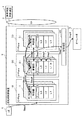
図1は本発明を実施する無線通信ネットワークの基地局制御装置を示すブロック構成図である。 FIG. 1 is a block diagram showing a base station control apparatus of a wireless communication network implementing the present invention.
基地局制御装置2は、ユーザ識別子とサービス識別子によって識別される呼の設定制御を行うCプレーン10と、ユーザデータの伝送処理を行うUプレーン20と、インターフェースを物理的に終端するTプレーン30とを備える。より詳しく説明すると、Cプレーン10は3GPPにおけるcontrol-planeのsignalingプロトコルを終端する機能を持ち、Uプレーン20はUMTS Radio Network
Layerのuser planeプロトコルの処理を行い、Tプレーン30はインタフェースに関連する機能を処理する機能を持つ。基地局制御装置2はまた、オペレータ5への情報通知のための記憶装置40を備える。
The base
The user plane protocol processing of the layer is performed, and the
それぞれのプレーンには一連の機能毎に複数のサブ制御装置11、21、31が設けられ、それぞれサブ制御装置識別子により識別される。各サブ制御装置は、機能毎に設けられた複数の処理エンティティ13、23または33と、これらの処理エンティティの動作を制御するとともに、いずれかの処理エンティティでエラーが発生した場合にはその情報を他のサブ制御装置に通知して必要なエラー処理を行う制御部12、22または32とを備える。各処理エンティティには処理エンティティ名が付与される。図1では、個々の処理エンティティをL1、L2、L3として示す。
Each plane is provided with a plurality of
基地局制御装置2が扱う呼には、自身が制御するエリア内にいるユーザ端末(UE:
User Equipment)1から発呼されるものと、他の無線/有線通信ネットワーク3に存在するユーザ端末から着呼するものと、他の基地局制御装置4で扱われていた呼がユーザ端末の移動に伴ってリロケーションされるものとがあり、各呼は、無線通信ネットワーク3内でユーザ端末を一意に特定するためのユーザ識別子と、無線通信ネットワーク3内で提供されるサービスを表すサービス識別子とによって識別される。
For calls handled by the base
User equipment) 1, calls received from user terminals existing in other wireless /
各ユーザ端末の接続パターンは、確立される呼が1つのシングルコールと、確立される呼が複数(CS(Circuit
Switched)+PS(Packet Switched)、CS+CSなど)のマルチコールがある。
The connection pattern of each user terminal is as follows: one call that is established and multiple calls that are established (CS (Circuit
Switched) + PS (Packet Switched), CS + CS, etc.).
ここで、Uプレーンの処理エンティティ23のうちL1で異常が発生した場合を例に、基地局制御装置2内でのエラー情報の収集について説明する。
Here, collection of error information in the base
Cプレーン10の制御部12は、呼を確立するタイミング、例えばユーザ端末からの呼確立要求を受信したタイミング(Step1)で、ユーザ識別子によって識別される特定ユーザの呼のアラーム出力要求をUプレーンおよびTプレーンへ送信する(Step2)。
The
一方、エラーを検知した処理エンティティL1は、エラー発生通知を上位レイヤの処理エンティティL2へ通知し(Step3)、処理エンティティL2がさらに上位レイヤの処理エンティティL3へ通知し(Step4)、これを繰り返して制御部22まで通知する(Step5)。
On the other hand, the processing entity L1 that detected the error notifies the error occurrence notification to the upper layer processing entity L2 (Step 3), and the processing entity L2 further notifies the upper layer processing entity L3 (Step 4). The
制御部22は、エラー通知受信後、他プレーンの制御部12、32へエラーの発生を通知し(Step6)、ユーザ識別子とサブ制御装置識別子とエラーの発生した処理エンティティ名とエラー理由とからなるアラーム情報を連結して記憶装置40に蓄え(Step7)、オペレータ5へ出力する。(Step8)。
After receiving the error notification, the
従来は、上述したStep7において記憶装置40に収集された情報をもとに、原因の究明を行っていた。本発明では、この原因究明のための情報収集に加え、必要最小限のアラーム情報を収集して通信オペレータに通知することを特徴とする。すなわち、Cプレーン10が呼を設定するために外部との間で送受信するメッセージの名称と、そのメッセージを用いて設定される呼のサービス識別子の組と、その呼を処理する処理エンティティ(L1、L2、L3)の名称との対応をテーブルとして備え、Cプレーン10のいずれかのサブ制御装置11において異常が検出された場合には、そのサブ制御装置11内の制御部12がその異常が検出された呼のメッセージ名、ユーザ識別子およびサービス識別子を含むエラー通知を各プレーンの制御部22、32に送り、Cプレーン10を含む各プレーンの制御部12、22、32は、エラー通知に示されたメッセージ名およびサービス識別子によりテーブルから処理エンティティ名を検索し、ユーザ識別子、サブ制御装置識別子および処理エンティティ名からなるアラーム情報を連結してオペレータ5に出力することを特徴とする。
Conventionally, the cause has been investigated based on the information collected in the
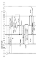
(実施例1)
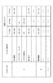
図2および図3を参照して、ユーザ端末からの呼確立時に異常が発生した場合を例に、本発明の実施例を説明する。図2はユーザ端末からの呼確立時に異常が発生した場合のアラーム情報の収集の処理の流れを示し、図3は本発明で用いるテーブルの一例を示す。
(Example 1)
With reference to FIG. 2 and FIG. 3, an embodiment of the present invention will be described by taking as an example a case where an abnormality occurs when a call from a user terminal is established. FIG. 2 shows a flow of alarm information collection processing when an abnormality occurs during call establishment from a user terminal, and FIG. 3 shows an example of a table used in the present invention.
ユーザ端末1が呼の確立要求メッセージを基地局制御装置2へ送信する(Step21)と、Cプレーン10の制御部12は、ユーザ端末1へ確立応答メッセージを送信し、メッセージ要求−応答タイマをセットする(Step22)。ここで、何らかの異常により、セットした時間内にユーザ端末1からの応答メッセージがなかったものとする。このときCプレーン10の制御部12は、タイマタイムアウトと判断し(Step23)、タイムアウトしたメッセージが正常系であるか解放系であるかを判別する(Step24)。メッセージが解放系である場合、特にアラーム情報の収集は不要なので、制御部12は、UプレーンおよびTプレーンのそれぞれの制御部22、23へ解放があったことのみを通知し、動作を終了する(Step25.1)。メッセージが正常系である場合、制御部12は、UプレーンおよびTプレーンのそれぞれの制御部22、32へ、メッセージ名とユーザ識別子とサービス識別子とを送信する(Step25.2)。各プレーンの制御部12、22、32は、メッセージ名とサービス識別子とからテーブルを検索し、処理エンティティ名を検索し(Step26)、ユーザ識別子、サブ制御装置識別子および処理エンティティ名からなるアラーム情報を一緒に記憶装置40へ出力する。オペレータは、任意の時間周期で出力されたアラーム情報を記憶装置40から取り出す(Step28)。
When the user terminal 1 transmits a call establishment request message to the base station controller 2 (Step 21), the
以上の実施例ではユーザ端末1からの呼確立要求時の異常の場合の動作例を説明したが、ユーザ端末への呼設定時や他ノードとのメッセージ送受信時にも同様に本発明を実施することができる。 In the above embodiment, an example of operation in the case of an abnormality at the time of a call establishment request from the user terminal 1 has been described. However, the present invention is similarly implemented when a call is set to the user terminal or when a message is transmitted to or received from another node. Can do.
1 ユーザ端末
2 基地局制御装置
3 通信ネットワーク
4 他の基地局制御装置
5 オペレータ
10 Cプレーン
20 Uプレーン
30 Tプレーン
40 記憶装置
11、21、31 サブ制御装置
12、22、32 制御部
13、23、33 処理エンティティ
1
Claims (4)
それぞれのプレーンには一連の機能毎に複数のサブ制御装置が設けられ、
それぞれのサブ制御装置は、機能毎に設けられた複数の処理エンティティと、これらの処理エンティティの動作を制御するとともに、いずれかの処理エンティティでエラーが発生した場合にはその情報を他のサブ制御装置に通知して必要なエラー処理を行う制御部とを備えた
無線通信ネットワークの基地局制御装置において、
前記Cプレーンが呼を設定するために外部との間で送受信するメッセージの名称と、そのメッセージを用いて設定される呼のサービス識別子の組と、その呼を処理する処理エンティティの名称との対応をテーブルとして蓄える手段を備え、
前記Cプレーンのいずれかのサブ制御装置において異常が検出された場合には、そのサブ制御装置内の制御部がその異常が検出された呼のメッセージ名、ユーザ識別子およびサービス識別子を含むエラー通知を各プレーンの制御部に送り、前記Cプレーンを含む各プレーンの制御部は、エラー通知に示されたメッセージ名およびサービス識別子により前記テーブルから処理エンティティ名を検索し、ユーザ識別子、サブ制御装置識別子および処理エンティティ名からなるアラーム情報を連結してオペレータに出力する
ことを特徴とする基地局制御装置。 A C plane that controls the setting of a call identified by a user identifier and a service identifier, a U plane that performs transmission processing of user data, and a T plane that physically terminates the interface,
Each plane is provided with multiple sub-control units for each series of functions,
Each sub-control device controls a plurality of processing entities provided for each function and the operation of these processing entities, and when an error occurs in any of the processing entities, the information is transferred to other sub-control units. In a base station controller of a wireless communication network comprising a control unit that notifies a device and performs necessary error processing,
Correspondence between the name of a message transmitted / received to / from the outside for setting up a call by the C plane, a set of service identifiers of a call set using the message, and a name of a processing entity that processes the call With means to store as a table,
When an abnormality is detected in any of the sub-control devices of the C plane, the control unit in the sub-control device sends an error notification including the message name, user identifier, and service identifier of the call in which the abnormality is detected. The control unit of each plane including the C plane searches the processing entity name from the table according to the message name and service identifier indicated in the error notification, and transmits the user identifier, the sub control device identifier, and A base station controller characterized in that alarm information comprising processing entity names is concatenated and output to an operator.
各プレーンの制御部は、正常系メッセージがタイムアウトになった場合を前記アラーム情報の出力の条件とする
請求項1記載の基地局制御装置。 Messages sent and received by the C plane are classified into normal messages for connecting calls and release messages for releasing calls,
The base station control device according to claim 1, wherein the control unit of each plane sets a condition for outputting the alarm information when a normal message times out.
前記Cプレーンが呼を設定するために外部との間で送受信するメッセージの名称と、そのメッセージを用いて設定される呼のサービス識別子の組と、その呼を処理する処理エンティティの名称との対応をテーブルとして設け、
前記Cプレーンのいずれかのサブ制御装置において異常が検出された場合には、そのサブ制御装置内の制御部がその異常が検出された呼のメッセージ名、ユーザ識別子およびサービス識別子を含むエラー通知を各プレーンの制御部に送り、前記Cプレーンを含む各プレーンの制御部は、エラー通知に示されたメッセージ名およびサービス識別子により前記テーブルから処理エンティティ名を検索し、ユーザ識別子、サブ制御装置識別子および処理エンティティ名からなるアラーム情報を連結してオペレータに出力する
ことを特徴とするアラーム情報収集方法。 A C-plane that performs setting control of a call identified by a user identifier and a service identifier, a U-plane that performs transmission processing of user data, and a T-plane that physically terminates an interface. Each plane includes a series of A plurality of sub-control devices are provided for each function, and each sub-control device controls a plurality of processing entities provided for each function and the operations of these processing entities, and an error occurs in any processing entity. In the alarm information collection method in the base station control device of the wireless communication network comprising a control unit for notifying the information to other sub-control device and performing necessary error processing when it occurs,
Correspondence between the name of a message transmitted / received to / from the outside for setting up a call by the C plane, a set of service identifiers of a call set using the message, and a name of a processing entity that processes the call As a table,
When an abnormality is detected in any of the sub-control devices of the C plane, the control unit in the sub-control device sends an error notification including the message name, user identifier, and service identifier of the call in which the abnormality is detected. The control unit of each plane including the C plane searches the processing entity name from the table according to the message name and service identifier indicated in the error notification, and transmits the user identifier, the sub control device identifier, and A method for collecting alarm information, characterized in that alarm information comprising processing entity names is concatenated and output to an operator.
Priority Applications (4)
| Application Number | Priority Date | Filing Date | Title |
|---|---|---|---|
| JP2005084138A JP4635671B2 (en) | 2005-03-23 | 2005-03-23 | Base station controller for wireless communication network and alarm information collecting method thereof |
| GB0605139A GB2424550B (en) | 2005-03-23 | 2006-03-14 | Base Station Controller For Radio Communication Network And Method Of Collecting Alarm Information Thereof |
| US11/377,570 US7715875B2 (en) | 2005-03-23 | 2006-03-17 | Base station controller for radio communication network and method of collecting alarm information thereof |
| CNB2006100585754A CN100556172C (en) | 2005-03-23 | 2006-03-22 | Be used for wireless communication network base station controller and method of collecting alarm information thereof |
Applications Claiming Priority (1)
| Application Number | Priority Date | Filing Date | Title |
|---|---|---|---|
| JP2005084138A JP4635671B2 (en) | 2005-03-23 | 2005-03-23 | Base station controller for wireless communication network and alarm information collecting method thereof |
Publications (2)
| Publication Number | Publication Date |
|---|---|
| JP2006270383A JP2006270383A (en) | 2006-10-05 |
| JP4635671B2 true JP4635671B2 (en) | 2011-02-23 |
Family
ID=36292742
Family Applications (1)
| Application Number | Title | Priority Date | Filing Date |
|---|---|---|---|
| JP2005084138A Expired - Fee Related JP4635671B2 (en) | 2005-03-23 | 2005-03-23 | Base station controller for wireless communication network and alarm information collecting method thereof |
Country Status (4)
| Country | Link |
|---|---|
| US (1) | US7715875B2 (en) |
| JP (1) | JP4635671B2 (en) |
| CN (1) | CN100556172C (en) |
| GB (1) | GB2424550B (en) |
Families Citing this family (4)
| Publication number | Priority date | Publication date | Assignee | Title |
|---|---|---|---|---|
| US20090196301A1 (en) * | 2007-05-14 | 2009-08-06 | Brian Parsons | Methods, systems and apparatus for monitoring and/or generating communications in a communications network |
| CN101515827B (en) | 2009-03-31 | 2011-12-07 | 中兴通讯股份有限公司 | Method for business wrong link resistance wrong in an automatic switched optical network and system thereof |
| CN102036261B (en) * | 2009-09-28 | 2014-03-12 | 中兴通讯股份有限公司 | Method and device for processing error indication in long term evolution (LTE) system |
| CN107801150B (en) * | 2017-10-19 | 2020-07-03 | 福建瑞聚信息技术股份有限公司 | GPS positioning polling base station alarm-based acquisition method and system |
Family Cites Families (12)
| Publication number | Priority date | Publication date | Assignee | Title |
|---|---|---|---|---|
| FI108599B (en) * | 1999-04-14 | 2002-02-15 | Ericsson Telefon Ab L M | Recovery in mobile communication systems |
| US7103002B2 (en) * | 2000-07-12 | 2006-09-05 | Telefonktiebolaget Lm Ericsson (Publ) | Communication management in networks having split control planes and user planes |
| FR2816159B1 (en) * | 2000-10-30 | 2002-12-06 | Mitsubishi Electric Inf Tech | METHOD FOR ESTABLISHING A RADIO LINK BETWEEN AN ACCESS CONTROLLER AND A BASE STATION |
| JP4623918B2 (en) | 2002-06-26 | 2011-02-02 | 日本電気株式会社 | Mobile communication system and operation control method thereof |
| EP1422968B1 (en) * | 2002-11-19 | 2010-01-13 | Alcatel Lucent | Failure localization in a transmission network |
| JP3882747B2 (en) | 2002-12-12 | 2007-02-21 | 日本電気株式会社 | Radio access network and operation control method thereof |
| JP2004247823A (en) | 2003-02-12 | 2004-09-02 | Nec Corp | Timing information compensation method, radio access network, and radio network controller |
| US20050063701A1 (en) * | 2003-09-23 | 2005-03-24 | Shlomo Ovadia | Method and system to recover resources in the event of data burst loss within WDM-based optical-switched networks |
| EP1531634A1 (en) * | 2003-11-13 | 2005-05-18 | Alcatel | Method for restoring a connection in a telecommunication network |
| JP4376601B2 (en) * | 2003-12-09 | 2009-12-02 | 富士通株式会社 | Network failure detection method and apparatus |
| US7590051B1 (en) * | 2004-09-22 | 2009-09-15 | Nortel Networks Limited | Method and apparatus for redialing a connection on a communication network |
| US7583593B2 (en) * | 2004-12-01 | 2009-09-01 | Cisco Technology, Inc. | System and methods for detecting network failure |
-
2005
- 2005-03-23 JP JP2005084138A patent/JP4635671B2/en not_active Expired - Fee Related
-
2006
- 2006-03-14 GB GB0605139A patent/GB2424550B/en not_active Expired - Fee Related
- 2006-03-17 US US11/377,570 patent/US7715875B2/en not_active Expired - Fee Related
- 2006-03-22 CN CNB2006100585754A patent/CN100556172C/en not_active Expired - Fee Related
Also Published As
| Publication number | Publication date |
|---|---|
| GB2424550B (en) | 2007-04-04 |
| US7715875B2 (en) | 2010-05-11 |
| CN1838815A (en) | 2006-09-27 |
| GB0605139D0 (en) | 2006-04-26 |
| GB2424550A (en) | 2006-09-27 |
| US20060217156A1 (en) | 2006-09-28 |
| JP2006270383A (en) | 2006-10-05 |
| CN100556172C (en) | 2009-10-28 |
Similar Documents
| Publication | Publication Date | Title |
|---|---|---|
| CN101616490B (en) | Method of deciding to release communication resources | |
| JP2005507626A (en) | Method for logging call processing methods in a mobile communication network | |
| CN102647307B (en) | A kind of method and system for reducing heartbeat message | |
| CN101646195B (en) | Method and device for detecting UMTS terminal | |
| CN103916526B (en) | Contact person information processing method, device and mobile terminal | |
| JP5599460B2 (en) | Method for communication between base stations, base station, and telecommunication network | |
| JP4635671B2 (en) | Base station controller for wireless communication network and alarm information collecting method thereof | |
| CN103634819A (en) | Mobile network signal blind zone discovery method and device | |
| CN117155829A (en) | Heartbeat detection method, device and system of network card, electronic equipment and storage medium | |
| EP2654278A1 (en) | Network maintenance system, method and device | |
| JP3607549B2 (en) | Wireless communication mobile station call processing data acquisition method and apparatus | |
| CN109699041B (en) | RRU channel fault diagnosis processing method, device and computer storage medium | |
| CN103621014B (en) | Autonomous self-jamming network element and method | |
| JP2015204538A (en) | Call processing sequence analyzer and communication system | |
| CN107547444B (en) | Traffic statistical method and switching equipment | |
| WO1997050209A1 (en) | A method for fault control of a telecommunications network and a telecommunications system | |
| JP5003896B2 (en) | Network monitoring system and network monitoring method | |
| EP1413153B1 (en) | An arrangement for cleaning up hanging pdp contexts in ggsn | |
| CN101548574B (en) | Communication control device and communication control method | |
| JP5221622B2 (en) | Wireless network control device, packet switch, circuit switch, and information notification method | |
| JP2016092656A (en) | Quality degradation analysis method, quality degradation analyzer, and network system | |
| CN103957079A (en) | Negotiation method and equipment in HDLC network | |
| CN104301927A (en) | Method and system for detecting WiFi hotspot access quantity | |
| JP5002038B2 (en) | Wireless network control apparatus and method | |
| CN101931918A (en) | A device and method for processing order service according to user status |
Legal Events
| Date | Code | Title | Description |
|---|---|---|---|
| A621 | Written request for application examination |
Free format text: JAPANESE INTERMEDIATE CODE: A621 Effective date: 20080111 |
|
| RD02 | Notification of acceptance of power of attorney |
Free format text: JAPANESE INTERMEDIATE CODE: A7422 Effective date: 20080214 |
|
| RD04 | Notification of resignation of power of attorney |
Free format text: JAPANESE INTERMEDIATE CODE: A7424 Effective date: 20080314 |
|
| A977 | Report on retrieval |
Free format text: JAPANESE INTERMEDIATE CODE: A971007 Effective date: 20100407 |
|
| A131 | Notification of reasons for refusal |
Free format text: JAPANESE INTERMEDIATE CODE: A131 Effective date: 20100413 |
|
| TRDD | Decision of grant or rejection written | ||
| A01 | Written decision to grant a patent or to grant a registration (utility model) |
Free format text: JAPANESE INTERMEDIATE CODE: A01 Effective date: 20101026 |
|
| A01 | Written decision to grant a patent or to grant a registration (utility model) |
Free format text: JAPANESE INTERMEDIATE CODE: A01 |
|
| A61 | First payment of annual fees (during grant procedure) |
Free format text: JAPANESE INTERMEDIATE CODE: A61 Effective date: 20101108 |
|
| FPAY | Renewal fee payment (event date is renewal date of database) |
Free format text: PAYMENT UNTIL: 20131203 Year of fee payment: 3 |
|
| R150 | Certificate of patent or registration of utility model |
Free format text: JAPANESE INTERMEDIATE CODE: R150 |
|
| LAPS | Cancellation because of no payment of annual fees |