JP4635549B2 - Information processing apparatus and method - Google Patents
Information processing apparatus and method Download PDFInfo
- Publication number
- JP4635549B2 JP4635549B2 JP2004289986A JP2004289986A JP4635549B2 JP 4635549 B2 JP4635549 B2 JP 4635549B2 JP 2004289986 A JP2004289986 A JP 2004289986A JP 2004289986 A JP2004289986 A JP 2004289986A JP 4635549 B2 JP4635549 B2 JP 4635549B2
- Authority
- JP
- Japan
- Prior art keywords
- audio
- output
- display device
- audio signal
- volume level
- Prior art date
- Legal status (The legal status is an assumption and is not a legal conclusion. Google has not performed a legal analysis and makes no representation as to the accuracy of the status listed.)
- Expired - Fee Related
Links
Images


Landscapes
- Television Receiver Circuits (AREA)
- Circuit For Audible Band Transducer (AREA)
Description
本発明は、情報処理装置および方法に関し、特に、2つの表示装置それぞれに出力するオーディオ信号を最適に制御することができるようにする情報処理装置および方法に関する。 The present invention relates to an information processing apparatus and method, and more particularly, to an information processing apparatus and method capable of optimally controlling an audio signal output to each of two display devices.
放送信号を受信し、テレビ番組を視聴したり、DVDを再生して、映画を視聴したりすることができるコンピュータ(パーソナルコンピュータ;Personal Computer(PC))がある。また、近年、PDP(Plasma Display Panel)やサラウンドシステムが普及し始めており、テレビ番組や映画を大画面モニタで視聴したいという要求がある。 There are computers (personal computers; personal computers (PCs)) that can receive broadcast signals, watch TV programs, play DVDs, and watch movies. In recent years, plasma display panels (PDPs) and surround systems have begun to spread, and there is a demand for viewing TV programs and movies on a large screen monitor.
そこで、コンピュータに2つの表示装置を接続可能とし、第1の表示装置では、通常のPCモニタとして、電子メール作成処理や文書作成処理などの画像を表示することができるようにし、さらに、コンピュータに第2の表示装置が接続された場合には、その第2の表示装置で、コンピュータ内のチューナが受信したテレビ番組を視聴したり、コンピュータ内のDVDドライブで再生された映画を視聴することができるようにすることが考えられる。 Therefore, it is possible to connect two display devices to the computer, and the first display device can display images such as e-mail creation processing and document creation processing as a normal PC monitor. When the second display device is connected, the second display device can watch a TV program received by a tuner in the computer or a movie played on a DVD drive in the computer. It is possible to make it possible.
この場合、第1の表示装置と第2の表示装置それぞれに出力するビデオ信号(映像)やオーディオ信号(音声)を、それぞれの目的に応じて最適に制御する必要がある。例えば、第2の表示装置で映画を再生表示している場合、第1の表示装置に表示させて実行しているその他のプログラムの処理音(例えば、電子メールが到着したときなどに発生するコンピュータのシステム音)は、第2の表示装置から聞こえてこないほうが良い。即ち、第2の表示装置には、DVDプレーヤで再生して視聴している場合と同様に、映画の映像や音声のみを出力するようにした方がよい。 In this case, it is necessary to optimally control the video signal (video) and audio signal (sound) output to each of the first display device and the second display device in accordance with each purpose. For example, when a movie is reproduced and displayed on the second display device, the processing sound of other programs displayed on the first display device and executed (for example, a computer generated when an e-mail arrives) It is better not to be heard from the second display device. That is, it is better to output only the video and audio of the movie to the second display device, as in the case of playing back and viewing with a DVD player.
従来のコンピュータにおいて、状況に応じてオーディオ信号を制御するものはある(例えば、特許文献1参照)。 Some conventional computers control audio signals according to the situation (see, for example, Patent Document 1).
しかしながら、従来のコンピュータの音声制御では、2つの表示装置を想定したものではなかった。 However, conventional audio control of a computer does not assume two display devices.
本発明は、このような状況に鑑みてなされたものであり、2つの表示装置それぞれに出力するオーディオ信号を最適に制御することができるようにするものである。 The present invention has been made in view of such a situation, and makes it possible to optimally control an audio signal output to each of two display devices.
本発明の情報処理装置は、オーディオ信号を出力する第1の音声出力手段と、第1の音声出力手段よりも高機能であって、オーディオ信号を出力する第2の音声出力手段と、第1または第2の表示装置にオーディオ信号を出力する音声出力手段として、第1または第2の音声出力手段を設定する制御を行う音声制御手段とを備え、音声制御手段は、第1の表示装置のみが使用される場合には、第1の表示装置にオーディオ信号を出力する音声出力手段として、第2の音声出力手段を設定し、第1の表示装置の他に、第2の表示装置も使用される場合には、第1の表示装置にオーディオ信号を出力する音声出力手段として、第1の音声出力手段を設定し、第2の表示装置にオーディオ信号を出力する音声出力手段として、第2の音声出力手段を設定することを特徴とする。 The information processing apparatus according to the present invention includes a first audio output unit that outputs an audio signal, a second audio output unit that outputs an audio signal, and has a higher function than the first audio output unit, Or, as a sound output means for outputting an audio signal to the second display device, a sound control means for performing control for setting the first or second sound output means is provided, and the sound control means is only for the first display device. Is used, the second audio output means is set as the audio output means for outputting the audio signal to the first display device, and the second display device is also used in addition to the first display device. In this case, the first sound output means is set as the sound output means for outputting the audio signal to the first display device, and the second sound output means for outputting the audio signal to the second display device is used as the second sound output means. Voice output means Characterized in that it constant.
第2の音声出力手段からのオーディオ信号は、第1および第2の表示装置に出力されるようになっており、第2の音声出力手段から第1の表示装置へのオーディオ信号の出力を遮断する遮断手段と、第1および第2の表示装置にOSD表示させる表示制御手段とをさらに設け、音声制御手段には、第1の表示装置の他に、第2の表示装置も使用される場合には、第2の音声出力手段から第1の表示装置へのオーディオ信号の出力を遮断するように遮断手段の制御もさせ、表示制御手段には、第1の音声出力手段が出力するオーディオ信号の音量レベルが変更された場合、第2の表示装置に、第1の音声出力手段が出力するオーディオ信号の音量レベルをOSD表示させることができる。 The audio signal from the second sound output means is output to the first and second display devices, and the output of the audio signal from the second sound output means to the first display device is cut off. And a display control means for causing OSD display on the first and second display devices, and a second display device is used as the sound control means in addition to the first display device. The control unit also controls the blocking unit so as to block the output of the audio signal from the second audio output unit to the first display device, and the display control unit causes the audio signal output by the first audio output unit to be output. When the volume level of the audio signal is changed, the volume level of the audio signal output from the first audio output means can be displayed on the second display device by OSD.
表示制御手段には、第1の音声出力手段が出力するオーディオ信号の音量レベルが変更された場合、第2の表示装置に表示される音量レベルのOSD表示付近に、そのOSD表示が第1の音声出力手段が出力するオーディオ信号の音量レベルであることを表す情報もOSD表示させることができる。 When the volume level of the audio signal output from the first audio output unit is changed, the display control unit displays the OSD display in the vicinity of the OSD display of the volume level displayed on the second display device. Information indicating the volume level of the audio signal output from the audio output means can also be displayed on the OSD.
表示制御手段には、第1の音声出力手段の音量レベルが変更された場合、第1の表示装置にも、第1の音声出力手段が出力するオーディオ信号の音量レベルをOSD表示させることができる。 When the volume level of the first sound output means is changed, the display control means can display the volume level of the audio signal output from the first sound output means on the first display device by OSD. .
第2の音声出力手段には、2種類の出力端子を介してオーディオ信号を出力し、2種類の出力端子のうちの一方の出力端子から出力されるオーディオ信号の音量レベルは、第1の音声出力手段が出力するオーディオ信号の音量レベルと連動させることができる。 The second audio output means outputs an audio signal via two types of output terminals, and the volume level of the audio signal output from one of the two types of output terminals is the first audio level. It can be linked with the volume level of the audio signal output by the output means.
音声制御手段には、第1の表示装置の他に、第2の表示装置も使用される場合には、第2の音声出力手段が出力するオーディオ信号の音量レベルを取得し、取得された音量レベルと同一の音量レベルに第1の音声出力手段が出力するオーディオ信号の音量レベルを設定した後で、第1の表示装置にオーディオ信号を出力する音声出力手段として第1の音声出力手段を設定し、第2の表示装置にオーディオ信号を出力する音声出力手段として第2の音声出力手段を設定させることができる。 When the second display device is used in addition to the first display device, the audio control unit acquires the volume level of the audio signal output by the second audio output unit, and the acquired volume level After setting the volume level of the audio signal output from the first audio output means to the same volume level as the level, the first audio output means is set as the audio output means for outputting the audio signal to the first display device. Then, the second sound output means can be set as the sound output means for outputting the audio signal to the second display device.
本発明の情報処理方法は、第1または第2の表示装置にオーディオ信号を出力する音声出力手段として、第1または第2の音声出力手段を設定する制御を行う音声制御ステップとを含み、音声制御ステップは、第1の表示装置のみが使用される場合には、第1の表示装置にオーディオ信号を出力する音声出力手段として、第1の音声出力手段よりも高機能な第2の音声出力手段を設定し、第1の表示装置の他に、第2の表示装置も使用される場合には、第1の表示装置にオーディオ信号を出力する音声出力手段として、第1の音声出力手段を設定し、第2の表示装置にオーディオ信号を出力する音声出力手段として、第2の音声出力手段を設定することを特徴とする。 The information processing method of the present invention includes a voice control step for performing control for setting the first or second voice output means as voice output means for outputting an audio signal to the first or second display device. When only the first display device is used, the control step is a second audio output that is higher in function than the first audio output unit as an audio output unit that outputs an audio signal to the first display device. When the second display device is used in addition to the first display device, the first audio output device is used as the audio output device that outputs an audio signal to the first display device. The second audio output means is set as the audio output means for setting and outputting the audio signal to the second display device.
本発明においては、第1および第2の音声出力手段のうち、第1の表示装置のみが使用される場合には、第1の表示装置にオーディオ信号を出力する音声出力手段として、第1の音声出力手段よりも高機能な第2の音声出力手段が設定され、第1の表示装置の他に、第2の表示装置も使用される場合には、第1の表示装置にオーディオ信号を出力する音声出力手段として、第1の音声出力手段が設定され、第2の表示装置にオーディオ信号を出力する音声出力手段として、第2の音声出力手段が設定される。 In the present invention, when only the first display device is used among the first and second sound output means, the first sound output means for outputting an audio signal to the first display device is the first sound output means. When the second audio output means having higher function than the audio output means is set and the second display device is used in addition to the first display device, an audio signal is output to the first display device. As the sound output means, the first sound output means is set, and as the sound output means for outputting the audio signal to the second display device, the second sound output means is set.
本発明によれば、2つの表示装置それぞれに出力するオーディオ信号を最適に制御することができる。 According to the present invention, the audio signal output to each of the two display devices can be optimally controlled.
以下に本発明の実施の形態を説明するが、請求項に記載の構成要件と、発明の実施の形態における具体例との対応関係を例示すると、次のようになる。この記載は、請求項に記載されている発明をサポートする具体例が、発明の実施の形態に記載されていることを確認するためのものである。従って、発明の実施の形態中には記載されているが、構成要件に対応するものとして、ここには記載されていない具体例があったとしても、そのことは、その具体例が、その構成要件に対応するものではないことを意味するものではない。逆に、具体例が構成要件に対応するものとしてここに記載されていたとしても、そのことは、その具体例が、その構成要件以外の構成要件には対応しないものであることを意味するものでもない。 Embodiments of the present invention will be described below. Correspondences between constituent elements described in the claims and specific examples in the embodiments of the present invention are exemplified as follows. This description is to confirm that specific examples supporting the invention described in the claims are described in the embodiments of the invention. Therefore, even if there are specific examples that are described in the embodiment of the invention but are not described here as corresponding to the configuration requirements, the specific examples are not included in the configuration. It does not mean that it does not correspond to a requirement. On the contrary, even if a specific example is described here as corresponding to a configuration requirement, this means that the specific example does not correspond to a configuration requirement other than the configuration requirement. not.
さらに、この記載は、発明の実施の形態に記載されている具体例に対応する発明が、請求項に全て記載されていることを意味するものではない。換言すれば、この記載は、発明の実施の形態に記載されている具体例に対応する発明であって、この出願の請求項には記載されていない発明の存在、すなわち、将来、分割出願されたり、補正により追加される発明の存在を否定するものではない。 Further, this description does not mean that all the inventions corresponding to the specific examples described in the embodiments of the invention are described in the claims. In other words, this description is an invention corresponding to the specific example described in the embodiment of the invention, and the existence of an invention not described in the claims of this application, that is, in the future, a divisional application will be made. Nor does it deny the existence of an invention added by amendment.
請求項1に記載の情報処理装置は、
第1または第2の表示装置にビデオ信号およびオーディオ信号を出力する処理を行う情報処理装置(例えば、図1のコンピュータ1)において、
前記オーディオ信号を出力する第1の音声出力手段(例えば、図5のオーディオデバイス28)と、
前記第1の音声出力手段よりも高機能であって、前記オーディオ信号を出力する第2の音声出力手段(例えば、図5のオーディオデバイス27)と、
前記第1または第2の表示装置に前記オーディオ信号を出力する音声出力手段として、前記第1または第2の音声出力手段を設定する制御を行う音声制御手段(例えば、図5の音声出力制御部112)と
を備え、
前記音声制御手段は、
前記第1の表示装置のみが使用される場合には、前記第1の表示装置に前記オーディオ信号を出力する音声出力手段として、前記第2の音声出力手段を設定し、
前記第1の表示装置の他に、前記第2の表示装置も使用される場合には、前記第1の表示装置に前記オーディオ信号を出力する音声出力手段として、前記第1の音声出力手段を設定し、前記第2の表示装置に前記オーディオ信号を出力する音声出力手段として、前記第2の音声出力手段を設定する
を備えることを特徴とする。
An information processing apparatus according to
In an information processing apparatus (for example, the
First audio output means for outputting the audio signal (for example, the
A second voice output means (for example, the
Voice control means for performing control for setting the first or second voice output means as voice output means for outputting the audio signal to the first or second display device (for example, the voice output control unit in FIG. 5) 112) and
The voice control means is
When only the first display device is used, the second sound output means is set as the sound output means for outputting the audio signal to the first display device,
When the second display device is used in addition to the first display device, the first audio output unit is used as an audio output unit that outputs the audio signal to the first display device. The second audio output means is set as an audio output means for setting and outputting the audio signal to the second display device.
請求項2に記載の情報処理装置は、
前記第2の音声出力手段からのオーディオ信号は、前記第1および第2の表示装置に出力されるようになっており、
前記第2の音声出力手段から前記第1の表示装置へのオーディオ信号の出力を遮断する遮断手段(例えば、図5のスイッチ102)と、
前記第1および第2の表示装置にOSD表示させる表示制御手段(例えば、図5の映像出力制御部111)と
をさらに備え、
前記音声制御手段は、前記第1の表示装置の他に、前記第2の表示装置も使用される場合には、前記第2の音声出力手段から前記第1の表示装置へのオーディオ信号の出力を遮断するように前記遮断手段の制御もし、
前記表示制御手段は、前記第1の音声出力手段が出力する前記オーディオ信号の音量レベルが変更された場合、前記第2の表示装置に、前記第1の音声出力手段が出力する前記オーディオ信号の音量レベルをOSD表示させる
ことを特徴とする。
The information processing apparatus according to
The audio signal from the second audio output means is output to the first and second display devices,
Blocking means (for example, switch 102 in FIG. 5) for blocking output of an audio signal from the second sound output means to the first display device;
Display control means (for example, video
When the second display device is used in addition to the first display device, the sound control unit outputs an audio signal from the second sound output unit to the first display device. Control of the blocking means so as to block,
When the volume level of the audio signal output from the first audio output unit is changed, the display control unit outputs the audio signal output from the first audio output unit to the second display device. The volume level is displayed on the OSD.
請求項7に記載の情報処理方法は、
第1および第2の音声出力手段を備え、第1または第2の表示装置にビデオ信号およびオーディオ信号を出力する処理を行う情報処理装置の情報処理方法において、
前記第1または第2の表示装置に前記オーディオ信号を出力する音声出力手段として、前記第1または第2の音声出力手段を設定する制御を行う音声制御ステップを含み、
前記音声制御ステップは、
前記第1の表示装置のみが使用される場合には、前記第1の表示装置に前記オーディオ信号を出力する音声出力手段として、前記第1の音声出力手段よりも高機能な前記第2の音声出力手段を設定し(例えば、図10のステップS43の処理)、
前記第1の表示装置の他に、前記第2の表示装置も使用される場合には、前記第1の表示装置に前記オーディオ信号を出力する音声出力手段として、前記第1の音声出力手段を設定し(例えば、図8のステップS6の処理)、前記第2の表示装置に前記オーディオ信号を出力する音声出力手段として、前記第2の音声出力手段を設定する(例えば、図8のステップS5の処理)
ことを特徴とする。
The information processing method according to claim 7 comprises:
In an information processing method of an information processing apparatus that includes first and second audio output means and performs processing of outputting a video signal and an audio signal to a first or second display device,
An audio control step for performing control to set the first or second audio output means as the audio output means for outputting the audio signal to the first or second display device;
The voice control step includes
When only the first display device is used, the second sound having higher function than the first sound output means as sound output means for outputting the audio signal to the first display device. Set the output means (for example, the process of step S43 in FIG. 10),
When the second display device is used in addition to the first display device, the first audio output unit is used as an audio output unit that outputs the audio signal to the first display device. The second audio output means is set as an audio output means for outputting the audio signal to the second display device (for example, step S6 in FIG. 8) (for example, step S5 in FIG. 8). Processing)
It is characterized by that.
以下、図を参照して、本発明の実施の形態について説明する。 Hereinafter, embodiments of the present invention will be described with reference to the drawings.
図1は、本発明を適用したコンピュータシステムの一実施の形態の構成例を示している。 FIG. 1 shows a configuration example of an embodiment of a computer system to which the present invention is applied.
図1のコンピュータシステムは、コンピュータ1、VGA(Video Graphics Array)モニタ2、並びにTV(TeleVision)モニタ3およびサラウンドシステム4からなるTVセット5により構成されている。
The computer system shown in FIG. 1 includes a
コンピュータ1は、受信した放送信号によるテレビ番組や、DVD(Digital Versatile Disk)を再生することにより得られる映画などのコンテンツの映像(ビデオ信号)や音声(オーディオ信号)を、所定の出力端子からVGAモニタ2またはTVモニタ3に出力する。また、コンピュータ1は、例えば、ハードディスクレコーダやVCR(Video Cassette Recorder)、またはDVDプレーヤなどの記録再生装置や、デジタルカメラ(デジタルスチルカメラまたはデジタルビデオカメラ)などの撮像装置から、所定の入力端子を介して、映像(ビデオ信号)や音声(オーディオ信号)を入力させる。
The
なお、コンピュータ1には、OS(Operating System)としてウィンドウズ(登録商標)(Windows(登録商標))がインストールされており、そのOS上で動作する表計算作成処理ソフトや文書作成処理ソフトなどの所定のアプリケーションプログラムもインストールされている。また、コンピュータ1では、インターネットなどのネットワークに接続することができるようになっており、所望のWebサーバ等にアクセスすることもできる。
In addition, Windows (registered trademark) (Windows (registered trademark)) is installed in the
VGAモニタ2は、例えば、LCD(Liquid Crystal Display)などにより構成される画面11を有し、コンピュータ1の出力端子とアナログRGBケーブルまたはDVI(Digital Visual Interface)などにより接続されている。これにより、VGAモニタ2は、コンピュータ1から供給されるビデオ信号に従い、所定の映像を画面11に表示する。例えば、VGAモニタ2は、ウィンドウズ(登録商標)や、表計算作成処理ソフト、文書作成ソフト、またはメール送受信ソフト(メーラー)等が作成するウィンドウなどの画像を画面(表示領域)11に表示する。なお、VGAモニタ2は、画面11の解像度を、640×480(VGA)の他、1024×768(SVGA(Super Video Graphics Array))、1280×1024(SXGA(Super eXtended Graphics Array))などでも表示することが可能である。
The VGA monitor 2 has, for example, a
一方、TVモニタ3は、信号フォーマットが525i,525p,1125i、および750p(後述)の放送信号を受信して、表示することが可能なテレビジョン受像機である。TVモニタ3の画面(表示領域)12は、LCDやPDP(Plasma Display Panel)などで構成され、VGAモニタ2の画面11より大きな画面となっている。
On the other hand, the TV monitor 3 is a television receiver capable of receiving and displaying broadcast signals having signal formats of 525i, 525p, 1125i, and 750p (described later). The screen (display area) 12 of the TV monitor 3 is configured by an LCD, a PDP (Plasma Display Panel), or the like, and is larger than the
また、TVモニタ3は、信号フォーマットが525i,525p,1125i、および750pのコンポーネント・ビデオ信号を入力することが可能な外部入力端子を有しており、そこにコンピュータ1の出力端子(ビデオ出力端子)からのビデオ信号が入力されている。
The TV monitor 3 has an external input terminal capable of inputting component video signals having signal formats of 525i, 525p, 1125i, and 750p, and the output terminal (video output terminal) of the
さらに、TVモニタ3は、6チャンネル(5.1チャンネル)のオーディオ信号を入力することが可能な外部入力端子も有しており、そこにコンピュータ1の出力端子(オーディオ出力端子)からのオーディオ信号が入力されている。そして、TVモニタ3に入力されたオーディオ信号は、TVモニタ3と接続されたサラウンドシステム4から、右、左、フロント(中央)、リア左、リア右、サブウーハーの合計6チャンネル(5.1チャンネル)の音声として出力される。
Furthermore, the TV monitor 3 also has an external input terminal capable of inputting 6-channel (5.1-channel) audio signals, and the audio signal from the output terminal (audio output terminal) of the
以上のように構成されるコンピュータシステムでは、ユーザは、VGAモニタ2をメインのモニタとして使用し、TVモニタ3をサブのモニタとして使用する。即ち、通常は、コンピュータ1からの映像または音声は、VGAモニタ2に出力されるようになっており、ユーザは、文書作成処理や電子メールの作成および送受信、Webページの閲覧などの作業を、VGAモニタ2の画面11に表示された映像(画像)を参照して行う。そして、ユーザが、テレビ番組やDVDの再生による映画などのコンテンツを大画面で、またはVGAモニタ2とは独立した画面で鑑賞したいときなどに、コンピュータ1を操作することによりTVモニタ用アプリケーションを起動させる。TVモニタ用アプリケーションは、ユーザに指定されたコンテンツの映像をTVモニタ3に出力し、音声をサラウンドシステム4から出力させる。
In the computer system configured as described above, the user uses the
次に、図2を参照して、TVモニタ3が受信または入力可能なビデオ信号の信号フォーマットについて説明する。上述したように、TVモニタ3は、525i,525p,1125i、および750pのビデオ信号(放送信号)を入力することができる。 Next, a signal format of a video signal that can be received or input by the TV monitor 3 will be described with reference to FIG. As described above, the TV monitor 3 can input 525i, 525p, 1125i, and 750p video signals (broadcast signals).
ここで、525iの信号フォーマットは、図2に示すように、ビデオ信号の走査線数(解像度)が525本であり、ビデオ信号の有効走査線数が480本であり、ビデオ信号の走査方式がインターレース(飛び越し走査方式)であることを表している。 Here, as shown in FIG. 2, the signal format of 525i has 525 scanning lines (resolution) of the video signal, 480 effective scanning lines of the video signal, and the scanning method of the video signal is This indicates interlace (interlace scanning method).
また、525pの信号フォーマットは、ビデオ信号の走査線数が525本であり、ビデオ信号の有効走査線数が480本であり、ビデオ信号の走査方式がプログレッシブ(順次走査方式)であることを表している。 The signal format of 525p indicates that the number of scanning lines of the video signal is 525, the number of effective scanning lines of the video signal is 480, and the scanning method of the video signal is progressive (sequential scanning method). ing.
同様に、1125iの信号フォーマットは、ビデオ信号の走査線数が1125本であり、ビデオ信号の有効走査線数が1080本であり、ビデオ信号の走査方式がインターレース(飛び越し走査方式)であることを表している。 Similarly, the 1125i signal format has 1125 video signal scanning lines, 1080 video signal effective scanning lines, and the video signal scanning method is interlaced (interlaced scanning method). Represents.
750pの信号フォーマットは、ビデオ信号の走査線数が750本であり、ビデオ信号の有効走査線数が720本であり、ビデオ信号の走査方式がプログレッシブ(順次走査方式)であることを表している。 The signal format of 750p indicates that the number of scanning lines of the video signal is 750, the number of effective scanning lines of the video signal is 720, and the scanning method of the video signal is progressive (sequential scanning method). .
なお、525iのコンポーネント・ビデオ信号のみが入力可能な端子は、EIAJ(Electronic Industries Association of Japan;日本電子機械工業会)のCP-4120の規格では、D1端子と呼ばれている。 Note that a terminal capable of inputting only a 525i component video signal is called a D1 terminal in the CP-4120 standard of EIAJ (Electronic Industries Association of Japan).
また、525pのコンポーネント・ビデオ信号を入力可能な端子は、525iのコンポーネント・ビデオ信号も入力可能となっており、EIAJのCP-4120の規格では、D2端子と呼ばれている。 A terminal capable of inputting a 525p component video signal can also input a 525i component video signal, and is called a D2 terminal in the EIAJ CP-4120 standard.
1125iのコンポーネント・ビデオ信号を入力可能な端子は、525iおよび525pのコンポーネント・ビデオ信号も入力可能となっており、EIAJのCP-4120の規格では、D3端子と呼ばれている。 Terminals capable of inputting 1125i component video signals can also input 525i and 525p component video signals, and are called D3 terminals in the EIAJ CP-4120 standard.
750pのコンポーネント・ビデオ信号を入力可能な端子は、525i,525p、および1125iのコンポーネント・ビデオ信号も入力可能となっており、EIAJのCP-4120の規格では、D4端子と呼ばれている。 Terminals capable of inputting 750p component video signals can also input 525i, 525p, and 1125i component video signals, and are called D4 terminals in the EIAJ CP-4120 standard.
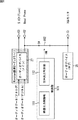
図3は、図1のコンピュータ1の構成例を示すブロック図である。
FIG. 3 is a block diagram illustrating a configuration example of the
図3において、CPU(Central Processing Unit)21は、ROM(Read Only Memory)22に記憶されているプログラム、またはHDD(Hard Disk Drive)32からRAM(Random Access Memory)23にロードされたプログラムに従って各種の処理を実行する。RAM23にはまた、CPU21が各種の処理を実行する上において必要なデータなども適宜記憶される。
In FIG. 3, a CPU (Central Processing Unit) 21 performs various processes according to a program stored in a ROM (Read Only Memory) 22 or a program loaded from a HDD (Hard Disk Drive) 32 to a RAM (Random Access Memory) 23. Execute the process. The
ここで、HDD32からRAM23にロードされ、CPU21において処理が実行されるプログラム(アプリケーション)としては、上述したOSや表計算作成処理ソフトの他、コンピュータ1からの音声の出力を制御する音声出力制御プログラム、コンピュータ1からの映像の出力を制御する映像出力制御プログラムなどがある。
Here, as a program (application) loaded from the
CPU21、ROM22、およびRAM23は、バス24を介して相互に接続されている。このバス24にはまた、入出力インタフェース25も接続されている。
The
入出力インタフェース25には、図示せぬアンテナより供給される放送信号を受信し、所定のチャンネルの放送信号を検波、復調するチューナ26、オーディオ信号(音声)を生成するオーディオデバイス(メイン)27およびオーディオデバイス(サブ)28、キーボード、マウスなどよりなる操作部29、外部からのビデオ信号(映像)またはオーディオ信号(音声)を入力させる入力部30、ビデオ信号(映像)またはオーディオ信号(音声)を外部の装置に出力する出力部31、所定のデータを記憶(記録)するHDD32、モデム、ターミナルアダプタなどより構成される通信部33、並びに、DVD71の記録または再生を行うDVDドライブ34が接続されている。
The input /
入出力インタフェース25にはまた、必要に応じてドライブ35が接続され、磁気ディスク(フロッピディスクを含む)、光ディスク(CD-ROM(Compact Disk-Read Only Memory)、光磁気ディスク(MD(Mini-Disk)を含む)、或いは半導体メモリなどのリムーバブルメディア(記録媒体)72が適宜装着され、それらから読み出されたコンピュータプログラムが、必要に応じてHDD32にインストールされる。
A
入力部30は、輝度信号と色信号をセパレートさせたビデオ信号を入力させるS(S映像)入力端子41、コンポジット・ビデオ信号を入力させるコンポジット入力端子42、並びにオーディオ信号を入力させるオーディオ入力端子43を少なくとも有している。
The
出力部31は、音声出力部(オーディオ出力端子)51と映像出力部(ビデオ出力端子)52とで構成されている。
The
音声出力部51は、VGAモニタ2に内蔵されているスピーカにオーディオ信号(音声)を出力するVGAモニタ(V)出力端子61、ヘッドフォン(Head Phone)にオーディオ信号(音声)を出力するヘッドフォン(H)出力端子62、並びにオーディオ信号(音声)をサラウンド出力するサラウンド(5.1CH)出力端子63を少なくとも有している。なお、VGAモニタ出力端子61およびヘッドフォン出力端子62からのオーディオ信号は、音量レベルを変更して出力することができるが、サラウンド出力端子63はRCA端子となっており、音量レベルを変更して出力することはできない(出力される音量レベルは固定である)。
The
図1のコンピュータシステムでは、VGAモニタ出力端子61が、所定のケーブルを介して、VGAモニタ2と接続されている。また、サラウンド出力端子63が、所定のケーブルを介して、TVモニタ3と接続されている。
In the computer system of FIG. 1, a VGA
映像出力部52は、輝度信号と色信号をセパレートさせたビデオ信号を出力するS(S映像)出力端子64、コンポジット・ビデオ信号を出力するコンポジット(CS)出力端子65、コンポーネント・ビデオ信号を出力するコンポーネント(CP)出力端子66、並びに、アナログRGBまたはDVI(Digital Visual Interface)などによりVGAモニタ2用のビデオ信号を出力するVGAモニタ(V)出力端子67を少なくとも有している。
The
図1のコンピュータシステムでは、VGAモニタ出力端子67が、所定のケーブルを介して、VGAモニタ2と接続されている。また、コンポーネント出力端子66が、所定のケーブルを介して、TVモニタ3と接続されている。
In the computer system of FIG. 1, a VGA
HDD32は、上述したOSや表計算作成処理ソフト、音声出力制御プログラム、映像出力制御プログラムなどの各種の(アプリケーション)プログラムを、内蔵するハードディスクに記憶(記録)している。HDD32に記憶されているプログラムは、ユーザの操作に対応する操作部29からの操作信号に基づくCPU21の制御により、RAM23などにロードされる。
The
また、HDD32は、入力部30から入力される、例えば、デジタルカメラなどで撮影された映像(音声も含む)や、チューナ26が受信したテレビ番組の映像または音声なども記憶することができる。これにより、例えば、ユーザは、HDD32に記録されている、以前に録画したテレビ番組を再生して視聴したり、デジタルカメラで撮影した映像を編集し、HDD32に記憶させることができる。なお、テレビ番組やデジタルカメラの映像は、SD (Standard Definition)映像か、またはHD (High Definition)映像のどちらでもよい。
Further, the
以上のように構成されるコンピュータ1では、ユーザは、例えば、チューナ26で受信したテレビ番組の映像、DVDドライブ34で再生した映画やドラマの映像、または入力部30から入力されたデジタルカメラの映像(静止画、音声も含む)などを、出力部31からVGAモニタ2またはTVモニタ3に出力(表示)させて視聴したり、HDD32に記憶(記録)させることができる。なお、コンピュータ1には、チューナ26を複数設けるようにして、複数のチャンネルでそれぞれ放送されている複数のテレビ番組を同時に記録させるようにすることもできる。
In the
さて、図3を参照して説明したように、コンピュータ1は、2つのオーディオデバイス(メイン)27およびオーディオデバイス(サブ)28を有している。以下、オーディオデバイス(メイン)27をメインオーディオデバイス27、オーディオデバイス(サブ)28をサブオーディオデバイス28ともいう。
Now, as described with reference to FIG. 3, the
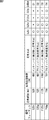
2つのオーディオデバイス27および28それぞれが有している機能には差がある。図4は、オーディオデバイス27および28それぞれが有している機能(性能)を示している。
There are differences in the functions of the two
メインオーディオデバイス27は、サブオーディオデバイス28よりも高機能を有している。
The
即ち、メインオーディオデバイス27は、Resolution(解像度,量子化ビット数)が20ビット(bit)で8チャンネル(ch)のA/D(Analog to Digital)変換、およびResolutionが24ビット(bit)で8チャンネル(ch)のD/A(Digital to Analog)変換を有している。
That is, the
また、メインオーディオデバイス27は、オーディオ入力として、LINEおよびCDのステレオ入力、PC-Beepのモノラル入力、ステレオおよびモノラルのマイク(Mic)入力、Optical(光)のSPDIF(Sony Philips Digital Interface)入力を有している。
The
さらに、メインオーディオデバイス27は、オーディオ出力として、LINEおよびLevel Outのステレオ出力、6(5.1)チャンネルおよび8(7.1)チャンネルのマルチチャンネル(サラウンド)出力、Optical(光)およびCoaxial(同軸)のSPDIF出力を有している。
Furthermore, the
その他、メインオーディオデバイス27は、SRC(Sample Rate Converter),32K,44.1K,48K,96K,および192KのSample Rates,MIC boost,AC3(Audio Code number 3)-Encoder,Analog mixer、並びにDigital mixerを有している。
In addition, the
一方、サブオーディオデバイス28は、Resolutionが16ビット(bit)で2チャンネル(ch)のD/A(Digital to Analog)変換、オーディオ出力として、LINEのステレオ出力、並びに、44.1Kおよび48KのSample Ratesを有しているのみである。
On the other hand, the
以上の機能のうち、D/A変換の解像度およびチャンネルが、メインオーディオデバイス27は、24ビットおよび8チャンネルで、サブオーディオデバイス28は、16ビットおよび2チャンネルであり、Sample Ratesが、メインオーディオデバイス27は、サブオーディオデバイス28より高い周波数(96Kおよび192K)も可能であることから、メインオーディオデバイス27は、サブオーディオデバイス28よりも高音質のオーディオ信号を出力することができる。
Of the above functions, the resolution and channel of D / A conversion are 24 bits and 8 channels for the
なお、図4のオーディオデバイス27および28それぞれが有している機能は、あくまで一例であり、オーディオデバイス27および28それぞれは、図4では有していないことになっている機能を有していても良いし、図4に示している機能以外の機能を有していてもよい。また、コンピュータ1は、各オーディオデバイスが有している全ての機能を必ずしも使用する必要はない。
Note that the functions of each of the
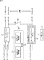
図5は、コンピュータ1が音声出力部51から音声出力を行う場合の機能的な構成例を示すブロック図である。なお、図5において、図3と対応する部分には同一の符号を付してある。
FIG. 5 is a block diagram illustrating an example of a functional configuration when the
メインオーディオデバイス27には、例えば、PCM(Pulse Code Modulation)データなどの、アナログまたはデジタルのオーディオデータが入力される。ここで、アナログで入力されるオーディオデータは、例えば、チューナ26が受信した放送信号のデータである。また、デジタルで入力されるオーディオデータは、例えば、HDD32またはDVD71に記録されているコンテンツ(テレビ番組や映画、楽曲など)のデータである。
For example, analog or digital audio data such as PCM (Pulse Code Modulation) data is input to the
メインオーディオデバイス27は、入力されたオーディオデータを、必要に応じてA/D変換などを施し、オーディオ信号に変換して、ヘッドフォン出力端子62およびサラウンド(5.1CH)出力端子63に出力する。
The
サブオーディオデバイス28には、入出力インタフェース25(図3)を介して、デジタルのオーディオデータのみが入力される。サブオーディオデバイス28は、入力されたオーディオデータをオーディオ信号に変換して、VGAモニタ出力端子61に出力する。
Only digital audio data is input to the
なお、メインオーディオデバイス27のヘッドフォン出力端子62への出力と、サブオーディオデバイス28のVGAモニタ出力端子61への出力とは、スイッチ(SW)102を介して接続されており、スイッチ102は、制御部101の制御によって、オンまたはオフするようになされている。
The output to the
制御部101は、コンピュータ1の、映像の出力を制御する映像出力制御部111と、音声の出力を制御する音声出力制御部112とにより構成されている。
The
映像出力制御部111は、例えば、オーディオデバイス27または28の音量レベルが変更された場合に、VGAモニタ2の画面11またはTVモニタ3の画面12(図1)に音量レベルのOSD(On Screen Display)表示をさせる。
For example, when the volume level of the
音声出力制御部112は、例えば、コンピュータ1がVGAモニタ2のみに映像を表示(出力)しているか、またはVGAモニタ2およびTVモニタ3の両方に映像を表示(出力)しているかに応じて、ウィンドウズ(登録商標)標準オーディオデバイスにメインオーディオデバイス27またはサブオーディオデバイス28をセットする。ここで、ウィンドウズ(登録商標)標準オーディオデバイスとは、ウィンドウズ(登録商標)のシステム設定などを行うコントロールパネルウィンドウの「サウンドとオーディオデバイスのプロパティ」で設定されているオーディオデバイスを表し、ウィンドウズ(登録商標)にインストールされているアプリケーションが、使用するオーディオデバイスをアプリケーション(またはソースプログラム)内において特に設定していない場合に使用されるオーディオデバイスを表している。
The audio
また、音声出力制御部112は、上述したように、スイッチ102を制御し、オンまたはオフさせる。
In addition, the audio
図5において、制御部101は、図3のCPU21が実行する処理に対応し、映像出力制御部111は、映像出力制御プログラムが実行する処理に、音声出力制御部112は、音声出力制御プログラムが実行する処理に、それぞれ対応する。
In FIG. 5, the
図6は、コンピュータ1の映像出力先として、VGAモニタ2のみが設定されている場合の、音声出力制御部112によるメインオーディオデバイス27、サブオーディオデバイス28、およびスイッチ102の制御状態を示している。
FIG. 6 shows the control state of the
コンピュータ1の映像出力先として、VGAモニタ2のみが設定されている場合、音声出力制御部112は、ウィンドウズ(登録商標)標準オーディオデバイスにメインオーディオデバイス27をセットする。また、音声出力制御部112は、スイッチ102をオンさせる。
When only the
これにより、メインオーディオデバイス27からのオーディオ信号は、VGAモニタ出力端子61、ヘッドフォン出力端子62、およびサラウンド出力端子63の全てに出力される。
Thus, the audio signal from the
従って、例えば、電子メールが到着したときなどに発生するコンピュータのシステム音や、DVDドライブ34で再生される映画や楽曲などの、コンピュータ1からの音声(オーディオ信号)は、VGAモニタ出力端子61、ヘッドフォン出力端子62、およびサラウンド出力端子63の全てに出力される。
Therefore, for example, the computer system sound generated when an e-mail arrives or the sound (audio signal) from the
なお、サブオーディオデバイス28にはオーディオデータが供給されず、サブオーディオデバイス28は使用されない。従って、VGAモニタ出力端子61から出力される音声がメインオーディオデバイス27からのオーディオ信号とサブオーディオデバイス28からのオーディオ信号とが重なった音声となることはない。
Note that audio data is not supplied to the
また、図6に示す制御状態は、コンピュータ1の映像出力先として、VGAモニタ2のみが設定されている場合であるので、TVモニタ3は、一般的には、オフしているか、あるいは、コンピュータ1からのオーディオ信号出力とは無関係の、例えば、TVモニタ3自身が受信したテレビ番組などの、映像を表示しているはずであるので、実質的には、VGAモニタ出力端子61とヘッドフォン出力端子62の2箇所から、コンピュータ1の音声が出力されることになる。勿論、TVモニタ3が映像の表示を外部入力に切り替えた場合には、サラウンドシステム4からもコンピュータ1の音声が出力されることになる。
Further, since the control state shown in FIG. 6 is when only the
以上のように、VGAモニタ2のみが使用されている場合には、VGAモニタ2にオーディオ信号を出力するオーディオデバイスとして、メインオーディオデバイス27が音声出力制御部112により設定される。
As described above, when only the
一方、ユーザによりTVモニタ用アプリケーションが起動され、TVモニタ用アプリケーションが、所定のコンテンツの映像をTVモニタ3に表示させる場合には、メインオーディオデバイス27、サブオーディオデバイス28、およびスイッチ102の制御状態は、図7に示すようになる。
On the other hand, when the TV monitor application is activated by the user and the TV monitor application displays a video of predetermined content on the TV monitor 3, the control state of the
即ち、図7は、コンピュータ1の映像出力先として、VGAモニタ2以外にTVモニタ3も設定されている場合の、音声出力制御部112によるメインオーディオデバイス27、サブオーディオデバイス28、およびスイッチ102の制御状態を示している。
That is, FIG. 7 shows the
音声出力制御部112は、ウィンドウズ(登録商標)標準オーディオデバイスにサブオーディオデバイス28をセットする。また、音声出力制御部112は、TVモニタ用アプリケーションが使用するオーディオデバイスにメインオーディオデバイス27をセットする。さらに、音声出力制御部112は、スイッチ102をオフさせる。
The audio
これにより、例えば、電子メールが到着したときなどに発生するコンピュータのシステム音などの音声(オーディオ信号)は、サブオーディオデバイス28によって、VGAモニタ出力端子61のみから出力される。そして、テレビ番組やDVDの再生などのTVモニタ用アプリケーションの音声(オーディオ信号)は、メインオーディオデバイス27によってヘッドフォン出力端子62と、サラウンド(5.1CH)出力端子63の2箇所から出力される。
Thereby, for example, a sound (audio signal) such as a computer system sound generated when an e-mail arrives is output from the VGA
以上のように、VGAモニタ2の他に、TVモニタ3も使用される場合には、VGAモニタ2にオーディオ信号を出力するオーディオデバイスとして、サブオーディオデバイス28が設定され、TVモニタ3にオーディオ信号を出力するオーディオデバイスとして、メインオーディオデバイス27が設定される。
As described above, when the TV monitor 3 is used in addition to the
次に、図8のフローチャートを参照して、TVモニタ用アプリケーションが起動された時の、コンピュータ1のオーディオデバイス制御処理について説明する。
Next, an audio device control process of the
初めに、ステップS1において、音声出力制御部112は、いまウィンドウズ(登録商標)標準オーディオデバイスに設定されているオーディオデバイスを取得する。この時点におけるコンピュータ1の音声出力に関する制御状態は、上述した図6に示す制御状態であるので、音声出力制御部112は、ウィンドウズ(登録商標)標準オーディオデバイスとして、メインオーディオデバイス27を取得して、ステップS2に進む。
First, in step S1, the audio
ステップS2において、音声出力制御部112は、ステップS2で取得したオーディオデバイス(取得オーディオデバイス)の音量レベル(の設定)を取得して、ステップS3に進む。
In step S2, the audio
ステップS3において、音声出力制御部112は、サブオーディオデバイス28の音量レベル(の設定)を、ステップS2で取得した音量レベル(取得音量レベル)にセットして、ステップS4に進む。
In step S3, the audio
ステップS4において、音声出力制御部112は、スイッチ102をオフにして、ステップS5に進む。
In step S4, the audio
ステップS5において、音声出力制御部112は、TVモニタ用アプリケーションが使用するオーディオデバイスとして、メインオーディオデバイス27をセットして、ステップS6に進む。
In step S5, the audio
ステップS6において、音声出力制御部112は、ウィンドウズ(登録商標)標準オーディオデバイスとして、サブオーディオデバイス28をセットして、処理を終了する。
In step S6, the audio
以上のようにして、コンピュータ1の音声出力に関する制御状態は、図6に示した状態から、図7に示した状態に遷移する。
As described above, the control state relating to the audio output of the
図8のオーディオデバイス制御処理によれば、現在のウィンドウズ(登録商標)標準オーディオデバイスに設定されているメインオーディオデバイス27の音量レベルを取得し、取得された音量レベルと同一の音量レベルにサブオーディオデバイス28の音量レベルを設定した後で、ウィンドウズ(登録商標)標準オーディオデバイスとしてサブオーディオデバイス28を設定するので、ウィンドウズ(登録商標)標準オーディオデバイスを変更したことにより、コンピュータ1から出力される音声の音量が変化するということを防止することができる。
According to the audio device control process of FIG. 8, the volume level of the
また、図8のオーディオデバイス制御処理によれば、スイッチ102をオフする(メインオーディオデバイス27からVGAモニタ出力端子61へのオーディオ信号の出力を遮断する)ので、図8のオーディオデバイス制御処理が終了後、メインオーディオデバイス27からのオーディオ信号は、ヘッドフォン出力端子62およびサラウンド出力端子63から出力され、サブオーディオデバイス28からのオーディオ信号は、VGAモニタ出力端子61から出力されることになる。即ち、メインオーディオデバイス27またはサブオーディオデバイス28からの音声が、VGAモニタ出力端子61およびヘッドフォン出力端子62の両方から出力されることを防止することができる。
Further, according to the audio device control process of FIG. 8, the
なお、ステップS4乃至S6の各ステップの処理は、どの順番で実行しても良いし、並列に実行することも可能である。 Note that the processes of steps S4 to S6 may be executed in any order, and may be executed in parallel.
次に、図9のフローチャートを参照して、TVモニタ用アプリケーションが起動中の、オーディオデバイス27および28の音量レベル制御処理について説明する。
Next, the volume level control processing of the
初めに、ステップS21において、音声出力制御部112は、ウィンドウズ(登録商標)標準オーディオデバイスの音量レベルが変更されたか否かを判定する。ここで、TVモニタ用アプリケーション起動中のウィンドウズ(登録商標)標準オーディオデバイスはサブオーディオデバイス28であるので、音声出力制御部112は、サブオーディオデバイス28の音量レベルが変更されたか否かを判定し、サブオーディオデバイス28の音量レベルが変更されたと判定されるまで待機する。
First, in step S21, the audio
そして、ステップS21において、サブオーディオデバイス28の音量レベルが変更された場合、ステップS22に進み、音声出力制御部112は、変更されたウィンドウズ(登録商標)標準オーディオデバイス(サブオーディオデバイス28)の音量レベルと同一の音量レベルにメインオーディオデバイス27の音量レベルをセットして、ステップS21に戻り、それ以降の処理を繰り返す。
If the volume level of the
図9の音量レベル制御処理によれば、メインオーディオデバイス27と接続されているヘッドフォン出力端子62およびサラウンド出力端子63(2種類の出力端子)のうちの、RCA端子ではないヘッドフォン出力端子62(一方の出力端子)から出力されるオーディオ信号の音量レベルは、サブオーディオデバイス28の音量レベルと連動するので、ユーザは、ヘッドフォン出力端子62から出力されるオーディオ信号の音量レベルを変更することができる。
9, the headphone output terminal 62 (one of the
換言すれば、コンピュータ1にオーディオデバイスが2つ備えられていて、その2つのオーディオデバイスそれぞれが何の音声の出力に使用されているかをユーザに意識させることなく、両方のオーディオデバイスの音量レベルをユーザが変更することができる。
In other words, the
次に、図10のフローチャートを参照して、TVモニタ用アプリケーションが終了された時の、コンピュータ1のオーディオデバイス制御処理について説明する。
Next, an audio device control process of the
初めに、ステップS41において、音声出力制御部112は、スイッチ102をオンにして、ステップS42に進む。
First, in step S41, the audio
ステップS42において、音声出力制御部112は、ウィンドウズ(登録商標)標準オーディオデバイスがサブオーディオデバイス28であるか否かを判定する。ステップS42で、ウィンドウズ(登録商標)標準オーディオデバイスがサブオーディオデバイス28ではないと判定された場合、ステップS43をスキップして、処理を終了する。
In step S <b> 42, the audio
一方、ステップS42で、ウィンドウズ(登録商標)標準オーディオデバイスがサブオーディオデバイス28であると判定された場合、ステップS43に進み、ウィンドウズ(登録商標)標準オーディオデバイスとして、TVモニタ用アプリケーションが使用していたメインオーディオデバイス27をセットして、処理を終了する。
On the other hand, when it is determined in step S42 that the Windows (registered trademark) standard audio device is the
図10のオーディオデバイス制御処理により、コンピュータ1の音声出力に関する制御状態は、図7に示した状態から、図6に示した状態に遷移する(戻る)。
With the audio device control process of FIG. 10, the control state relating to the audio output of the
以上のように、コンピュータ1の音声出力制御部112は、コンピュータ1の映像出力先(表示装置)がVGAモニタ2のみの場合には、2つあるオーディオデバイス27および28のうちの高機能なオーディオデバイス27を使用してVGAモニタ2にオーディオ信号を出力し、コンピュータ1の映像出力先がVGAモニタ2およびTVモニタ3の場合には、オーディオデバイス27を使用してTVモニタ3にオーディオ信号を出力し、オーディオデバイス28を使用してVGAモニタ2にオーディオ信号を出力するようにする。
As described above, when the video output destination (display device) of the
これにより、チューナ26が受信したテレビ番組やDVDの再生映像などの音声のように、より高音質な音声を出力するオーディオデバイスに、メインオーディオデバイス27を設定することができる。また、ウィンドウズ(登録商標)標準オーディオデバイスに設定されているサブオーディオデバイス28に対する音量レベルの変更に連動して、メインオーディオデバイス27の音量レベルも変更される。
As a result, the
従って、音声出力制御部112は、2つの表示装置(VGAモニタ2およびTVモニタ3)それぞれに出力するオーディオ信号を最適に制御することができる。
Therefore, the audio
次に、図11を参照して、図7に示す制御状態、即ち、コンピュータ1の映像出力先として、VGAモニタ2以外にTVモニタ3も設定されている状態において、サブオーディオデバイス28の音量レベルが変更された場合の、音量レベルのOSD表示制御について説明する。
Next, referring to FIG. 11, the volume level of the
図11では、ウィンドウズ(登録商標)標準オーディオデバイスとしてサブオーディオデバイス28が設定され、TVモニタ用アプリケーションが使用するオーディオデバイスとして、メインオーディオデバイス27が設定されている。
In FIG. 11, a
例えば、ユーザは、TVモニタ用アプリケーションで、チューナ26(図3)が受信した所定のチャンネルのテレビ番組をTVモニタ3に表示させ、視聴しているとする。このとき、サラウンドシステム4から聴こえてくるテレビ番組の音声は、コンピュータ1のサラウンド(5.1CH)出力端子63から出力されたオーディオ信号によるものである。
For example, it is assumed that the user displays a TV program of a predetermined channel received by the tuner 26 (FIG. 3) on the TV monitor 3 and watches it with a TV monitor application. At this time, the sound of the television program heard from the
ユーザは、コンピュータ1に付属のリモートコントローラ(以下、リモコンという)141を操作して、チューナ26が受信するチャンネルを変更することができる。
The user can change a channel received by the
ところで、TVモニタ3は、それ自身でも、放送信号を受信して、所定のチャンネルのテレビ番組を表示することができるので、ユーザは、TVモニタ3に表示されているテレビ番組のチャンネルが、コンピュータ1のチューナ26が受信しているチャンネルであるか、またはTVモニタ3のチューナが受信しているチャンネルであるかを一見して見分けることができない。
By the way, the TV monitor 3 itself can receive a broadcast signal and display a TV program of a predetermined channel, so that the user can set the TV program channel displayed on the TV monitor 3 to a computer. It is impossible to tell at a glance whether the channel is received by one
従って、ユーザは、実際は、コンピュータ1のチューナ26が受信しているチャンネルを変更しているにもかかわらず、TVモニタ3のチューナが受信しているチャンネルを変更していると勘違いする可能性がある。
Therefore, there is a possibility that the user may mistakenly think that the channel received by the tuner of the TV monitor 3 is changed even though the channel received by the
しかしながら、そのような勘違いをしていたとしても、リモコン141で操作されたチャンネルに従って、TVモニタ3に表示される映像は切り替えられるので、問題は発生しない。
However, even if such a misunderstanding is made, the video displayed on the TV monitor 3 can be switched according to the channel operated by the
一方、ユーザがリモコン141で音量レベルを上げる操作を行った場合、サラウンドシステム4から聴こえてくる音声の音量レベルは変化しない。これは、サラウンド(5.1CH)出力端子63が出力音量固定のRCA端子であるからである。
On the other hand, when the user performs an operation to increase the volume level with the
しかしながら、ユーザは、TVモニタ3が受信しているチャンネルを変更していると勘違いをしていれば、サラウンドシステム4から出力される音声の音量レベルが変更されないのを疑問に思い、確認のため、何度もリモコン141の操作(音量レベルを上げる操作)を行うことが考えられる。
However, if the user misunderstands that the channel received by the TV monitor 3 is changed, the user wonders that the volume level of the sound output from the
そののち、ユーザは、何回かのリモコン141の操作によっても聴こえてくる音声の音量レベルが変化しないので、自分の操作の間違いに気づき、本来のTVモニタ3のリモコン(図示せず)で音量レベルの変更操作を行うと予想される。
After that, the user does not change the volume level of the sound that is heard even if the
このとき、ユーザは、コンピュータ1のリモコン141による操作では、聴こえてくる音声の音量レベルが変化していなかったので、コンピュータ1は何も変更されていないと思ってしまう。
At this time, the user thinks that the
しかしながら、コンピュータ1では、ユーザの音量レベルを上げるリモコン141の操作に応じて、VGAモニタ出力端子61およびヘッドフォン出力端子62の音量レベルが連動して上昇している。
However, in the
その結果、ユーザがヘッドフォン出力端子62にヘッドフォンを接続し、チューナ26が受信したテレビ番組の音声をヘッドフォンで聴こうとした場合、ヘッドフォンから大音量の音声が出力されたり、ユーザがVGAモニタ2上で何らかの操作(アプリケーション処理)を行っているときに、システム音が突然大音量で鳴ったりして、ユーザを驚愕させることになる。このようなユーザの誤操作による悪影響は、コンピュータ1のオーディオデバイス27および28の音量レベルが変更されていることにユーザが気が付かないことによる。
As a result, when the user connects a headphone to the
そこで、コンピュータ1では、ユーザがリモコン141において音量レベルを変更する操作を行った場合、それにより、コンピュータ1のオーディオデバイス27が出力する音声(オーディオ信号)の音量レベル(以下、適宜、コンピュータ1の音量レベルという)が変更されていることがユーザに分かるように、オーディオデバイス27が出力する音声の音量レベルをVGAモニタ2またはTVモニタ3上にOSD表示させる。
Therefore, in the
即ち、映像出力制御部111は、図12右側に示すように、TVモニタ3の画面12に、コンピュータ1の音量レベルであることを表す「PC音量」の文字の情報171とともに、コンピュータ1の音量レベル172をOSD表示させる。
That is, as shown on the right side of FIG. 12, the video
また、コンピュータ1の映像出力制御部111は、図12左側に示すように、VGAモニタ2の画面11にも、コンピュータ1の音量レベル161をOSD表示させる。
Further, the video
さらに、映像出力制御部111は、TVモニタ3の画面12上の、コンピュータ1の音量レベル172の上方に、TVモニタ3の音量レベル173もOSD表示させるようにしても良い。
Further, the video
なお、図12において、「PC音量」の文字の情報171の代わりに、PCを模したイメージ(画像)や、所定のマーク、記号などをOSD表示させてもよい。即ち、情報171は、音量レベル172がTVモニタ3の音量レベルではなくてコンピュータ1の音量レベルであることをユーザが認識することができるOSD表示であればなんでもよい。
In FIG. 12, instead of the
次に、図13のフローチャートを参照して、コンピュータ1の音量レベルのOSD表示制御処理を説明する。この処理は、コンピュータ1の音量レベルを変更する操作が行なわれた場合に実行される。
Next, the volume level OSD display control processing of the
初めに、ステップS61において、映像出力制御部111は、TVモニタ3にビデオ信号を出力しているか否かを判定する。
First, in step S61, the video
ステップS61で、TVモニタ3にビデオ信号を出力していないと判定された場合、ステップS62に進み、映像出力制御部111は、VGAモニタ2の画面11にコンピュータ1の音量レベルをOSD表示させて、処理を終了する。
If it is determined in step S61 that the video signal is not output to the TV monitor 3, the process proceeds to step S62, and the video
一方、ステップS61で、TVモニタ3にビデオ信号を出力していると判定された場合、ステップS63に進み、映像出力制御部111は、VGAモニタ2の画面11にコンピュータ1の音量レベルをOSD表示させるとともに、TVモニタ3の画面12にコンピュータ1の音量レベルをOSD表示させて、処理を終了する。
On the other hand, if it is determined in step S61 that a video signal is being output to the TV monitor 3, the process proceeds to step S63, where the video
以上のように、図13の音量レベルのOSD表示制御処理によれば、VGAモニタ2のみにコンピュータ1からの映像を表示している(ビデオ信号を出力している)場合には、VGAモニタ2にコンピュータ1の音量レベルをOSD表示させる。
As described above, according to the OSD display control processing at the volume level in FIG. 13, when the video from the
また、VGAモニタ2およびTVモニタ3それぞれにコンピュータ1からの映像を表示している場合には、VGAモニタ2およびTVモニタ3それぞれにコンピュータ1の音量レベルをOSD表示させる。さらに、図12に示したように、TVモニタ3に表示されるコンピュータ1の音量レベルのOSD表示付近に、コンピュータ1の音量レベルであることを表す情報もOSD表示させる。
When the video from the
これにより、ユーザは、自分がいま変更している音量レベルがコンピュータ1の音量レベルであることを容易に(即座に)認識することができ、コンピュータ1の音量レベルの誤操作およびそれによる悪影響を防止することができる。
Accordingly, the user can easily (immediately) recognize that the volume level that he / she is changing is the volume level of the
なお、上述した実施の形態では、コンピュータ1が有する2つのオーディオデバイス27および28は、一方のオーディオデバイス(オーディオデバイス27)が、他方のオーディオデバイス(オーディオデバイス28)に対して、高機能なオーディオデバイスであるとして説明したが、2つのオーディオデバイス27および28は、同一の機能を備えるオーディオデバイスであってもよい。即ち、オーディオデバイス27を2つ備えるようにしても良い。
In the above-described embodiment, the two
但し、上述した実施の形態のように、2つのオーディオデバイス27および28のうちの一方(メインオーディオデバイス27)だけを高機能なオーディオデバイスとし、TVモニタ3への映像の出力の有無に応じてウィンドウズ(登録商標)標準オーディオデバイスをオーディオデバイス27と28との間で切り替えることにより、コンピュータ1のオーディオデバイスにかかるコストを抑制しながら、DVDの再生などの高音質なオーディオ信号の出力を必要とする出力端子に、常に高機能なオーディオデバイスを割り当てることができる。
However, as in the above-described embodiment, only one of the two
また、上述した実施の形態では、説明を分かりやすくするため、TVモニタ3の画面12は、VGAモニタ2の画面11より大きいものとして説明したが、TVモニタ3の画面12は、必ずしもVGAモニタ2の画面11より大である必要はない。
In the above-described embodiment, the
また、本実施の形態では、2つのオーディオデバイスと、コンポーネント出力端子とを備える装置を、コンピュータとして説明したが、本発明は、コンピュータの他、HDD,DVDドライブ等を備える記録再生装置にも適用することが可能である。 Further, in the present embodiment, an apparatus including two audio devices and a component output terminal has been described as a computer. However, the present invention is applicable to a recording / reproducing apparatus including an HDD, a DVD drive, etc. in addition to a computer. Is possible.
なお、本明細書において、フローチャートに記述されたステップは、記載された順序に沿って時系列的に行われる処理はもちろん、必ずしも時系列的に処理されなくとも、並列的あるいは個別に実行される処理をも含むものである。 In the present specification, the steps described in the flowcharts are executed in parallel or individually even if they are not necessarily processed in time series, as well as processes performed in time series in the described order. It also includes processing.
また、本明細書において、システムとは、複数の装置により構成される装置全体を表すものである。 Further, in this specification, the system represents the entire apparatus constituted by a plurality of apparatuses.
1 コンピュータ, 21 CPU, 26 オーディオデバイス(メイン), 27 オーディオデバイス(サブ), 31 出力部, 51 音声出力部, 61 VGAモニタ出力端子, 62 ヘッドフォン出力端子, 63 サラウンド出力端子, 101 制御部, 102 スイッチ, 111 映像出力制御部, 112 音声出力制御部 1 computer, 21 CPU, 26 audio device (main), 27 audio device (sub), 31 output unit, 51 audio output unit, 61 VGA monitor output terminal, 62 headphone output terminal, 63 surround output terminal, 101 control unit, 102 Switch, 111 video output control unit, 112 audio output control unit
Claims (7)
前記オーディオ信号を出力する第1の音声出力手段と、
前記第1の音声出力手段よりも高機能であって、前記オーディオ信号を出力する第2の音声出力手段と、
前記第1または第2の表示装置に前記オーディオ信号を出力する音声出力手段として、前記第1または第2の音声出力手段を設定する制御を行う音声制御手段と
を備え、
前記音声制御手段は、
前記第1の表示装置のみが使用される場合には、前記第1の表示装置に前記オーディオ信号を出力する音声出力手段として、前記第2の音声出力手段を設定し、
前記第1の表示装置の他に、前記第2の表示装置も使用される場合には、前記第1の表示装置に前記オーディオ信号を出力する音声出力手段として、前記第1の音声出力手段を設定し、前記第2の表示装置に前記オーディオ信号を出力する音声出力手段として、前記第2の音声出力手段を設定する
ことを特徴とする情報処理装置。 In an information processing apparatus that performs processing for outputting a video signal and an audio signal to a first or second display device,
First audio output means for outputting the audio signal;
A second voice output means that is more functional than the first voice output means and outputs the audio signal;
Voice control means for performing control for setting the first or second voice output means as voice output means for outputting the audio signal to the first or second display device;
The voice control means is
When only the first display device is used, the second sound output means is set as the sound output means for outputting the audio signal to the first display device,
When the second display device is used in addition to the first display device, the first audio output unit is used as an audio output unit that outputs the audio signal to the first display device. An information processing apparatus, wherein the second audio output means is set as an audio output means for setting and outputting the audio signal to the second display device.
前記第2の音声出力手段から前記第1の表示装置へのオーディオ信号の出力を遮断する遮断手段と、
前記第1および第2の表示装置にOSD表示させる表示制御手段と
をさらに備え、
前記音声制御手段は、前記第1の表示装置の他に、前記第2の表示装置も使用される場合には、前記第2の音声出力手段から前記第1の表示装置へのオーディオ信号の出力を遮断するように前記遮断手段の制御もし、
前記表示制御手段は、前記第1の音声出力手段が出力する前記オーディオ信号の音量レベルが変更された場合、前記第2の表示装置に、前記第1の音声出力手段が出力する前記オーディオ信号の音量レベルをOSD表示させる
ことを特徴とする請求項1に記載の情報処理装置。 The audio signal from the second audio output means is output to the first and second display devices,
Blocking means for blocking output of an audio signal from the second sound output means to the first display device;
Display control means for causing OSD display on the first and second display devices,
When the second display device is used in addition to the first display device, the sound control unit outputs an audio signal from the second sound output unit to the first display device. Control of the blocking means so as to block,
When the volume level of the audio signal output from the first audio output unit is changed, the display control unit outputs the audio signal output from the first audio output unit to the second display device. The information processing apparatus according to claim 1, wherein the volume level is displayed in an OSD manner.
ことを特徴とする請求項2に記載の情報処理装置。 When the volume level of the audio signal output from the first audio output unit is changed, the display control unit displays the OSD display near the OSD display of the volume level displayed on the second display device. The information processing apparatus according to claim 2, wherein information indicating that the volume level of the audio signal output from the first audio output unit is OSD-displayed.
ことを特徴とする請求項2に記載の情報処理装置。 When the volume level of the first audio output unit is changed, the display control unit displays the volume level of the audio signal output from the first audio output unit on the first display device by OSD display. The information processing apparatus according to claim 2, wherein:
前記2種類の出力端子のうちの一方の出力端子から出力されるオーディオ信号の音量レベルは、前記第1の音声出力手段が出力する前記オーディオ信号の音量レベルと連動する
ことを特徴とする請求項1に記載の情報処理装置。 The second audio output means outputs an audio signal via two types of output terminals,
The volume level of the audio signal output from one of the two types of output terminals is linked to the volume level of the audio signal output from the first audio output means. The information processing apparatus according to 1.
ことを特徴とする請求項1に記載の情報処理装置。 When the second display device is used in addition to the first display device, the sound control unit acquires a volume level of the audio signal output by the second sound output unit, As audio output means for outputting the audio signal to the first display device after setting the volume level of the audio signal output by the first audio output means to the same volume level as the acquired volume level. The information according to claim 1, wherein the first audio output means is set, and the second audio output means is set as an audio output means for outputting the audio signal to the second display device. Processing equipment.
前記第1または第2の表示装置に前記オーディオ信号を出力する音声出力手段として、前記第1または第2の音声出力手段を設定する制御を行う音声制御ステップを含み、
前記音声制御ステップは、
前記第1の表示装置のみが使用される場合には、前記第1の表示装置に前記オーディオ信号を出力する音声出力手段として、前記第1の音声出力手段よりも高機能な前記第2の音声出力手段を設定し、
前記第1の表示装置の他に、前記第2の表示装置も使用される場合には、前記第1の表示装置に前記オーディオ信号を出力する音声出力手段として、前記第1の音声出力手段を設定し、前記第2の表示装置に前記オーディオ信号を出力する音声出力手段として、前記第2の音声出力手段を設定する
ことを特徴とする情報処理方法。 In an information processing method of an information processing apparatus that includes first and second audio output means and performs processing of outputting a video signal and an audio signal to a first or second display device,
An audio control step for performing control to set the first or second audio output means as the audio output means for outputting the audio signal to the first or second display device;
The voice control step includes
When only the first display device is used, the second sound having higher function than the first sound output means as sound output means for outputting the audio signal to the first display device. Set the output means,
When the second display device is used in addition to the first display device, the first audio output unit is used as an audio output unit that outputs the audio signal to the first display device. An information processing method comprising: setting the second sound output means as sound output means for setting and outputting the audio signal to the second display device.
Priority Applications (1)
| Application Number | Priority Date | Filing Date | Title |
|---|---|---|---|
| JP2004289986A JP4635549B2 (en) | 2004-10-01 | 2004-10-01 | Information processing apparatus and method |
Applications Claiming Priority (1)
| Application Number | Priority Date | Filing Date | Title |
|---|---|---|---|
| JP2004289986A JP4635549B2 (en) | 2004-10-01 | 2004-10-01 | Information processing apparatus and method |
Publications (2)
| Publication Number | Publication Date |
|---|---|
| JP2006108855A JP2006108855A (en) | 2006-04-20 |
| JP4635549B2 true JP4635549B2 (en) | 2011-02-23 |
Family
ID=36378096
Family Applications (1)
| Application Number | Title | Priority Date | Filing Date |
|---|---|---|---|
| JP2004289986A Expired - Fee Related JP4635549B2 (en) | 2004-10-01 | 2004-10-01 | Information processing apparatus and method |
Country Status (1)
| Country | Link |
|---|---|
| JP (1) | JP4635549B2 (en) |
Families Citing this family (5)
| Publication number | Priority date | Publication date | Assignee | Title |
|---|---|---|---|---|
| JP4920522B2 (en) | 2007-08-06 | 2012-04-18 | 株式会社東芝 | Information processing apparatus and output interlocking control method |
| JP5075745B2 (en) * | 2008-06-17 | 2012-11-21 | 株式会社東芝 | Information processing device |
| TWI377851B (en) * | 2008-12-22 | 2012-11-21 | Wistron Corp | Electronic device and system for controlling volume and method therefor |
| JP4900406B2 (en) | 2009-02-27 | 2012-03-21 | ソニー株式会社 | Information processing apparatus and method, and program |
| JP2010277253A (en) * | 2009-05-27 | 2010-12-09 | Toshiba Corp | Information processor and method for changing voice output destination |
Citations (15)
| Publication number | Priority date | Publication date | Assignee | Title |
|---|---|---|---|---|
| JPH04196880A (en) * | 1990-11-28 | 1992-07-16 | Hitachi Ltd | Television receiver |
| JPH0730971A (en) * | 1993-07-09 | 1995-01-31 | Hitachi Ltd | Av system controller |
| JPH07226800A (en) * | 1994-02-15 | 1995-08-22 | Oki Electric Ind Co Ltd | Inter-multi-spot conference equipment |
| JPH0898102A (en) * | 1994-09-22 | 1996-04-12 | Sony Corp | Television receiver |
| JPH08275080A (en) * | 1995-03-29 | 1996-10-18 | Matsushita Electric Ind Co Ltd | Wide television receiver |
| JPH09139894A (en) * | 1995-05-31 | 1997-05-27 | Samsung Electron Co Ltd | Television set that displays data related to audio balance adjustment |
| JPH11150788A (en) * | 1997-11-14 | 1999-06-02 | Yamaha Corp | Audio system |
| JP2000507752A (en) * | 1996-03-27 | 2000-06-20 | ゲートウェイ 2000,インコーポレイティド | Computer controlled home entertainment system |
| JP2001111906A (en) * | 1999-10-08 | 2001-04-20 | Matsushita Electric Ind Co Ltd | Digital broadcast receiver |
| JP2001216132A (en) * | 2000-01-28 | 2001-08-10 | Sony Corp | Information processor |
| JP2001268511A (en) * | 2000-03-15 | 2001-09-28 | Nippon Television Network Corp | Method and system for digital broadcast |
| JP2001326861A (en) * | 2000-05-15 | 2001-11-22 | Mitsubishi Electric Corp | Program selection device |
| JP2003032573A (en) * | 2001-07-19 | 2003-01-31 | Canon Inc | Display system, display device and controller |
| JP2004015635A (en) * | 2002-06-10 | 2004-01-15 | Sony Corp | Device and method for reproducing contents |
| WO2004084527A1 (en) * | 2003-03-17 | 2004-09-30 | Sanyo Electric Co., Ltd. | Mobile device having broadcast receiving function and telephone communication function |
-
2004
- 2004-10-01 JP JP2004289986A patent/JP4635549B2/en not_active Expired - Fee Related
Patent Citations (15)
| Publication number | Priority date | Publication date | Assignee | Title |
|---|---|---|---|---|
| JPH04196880A (en) * | 1990-11-28 | 1992-07-16 | Hitachi Ltd | Television receiver |
| JPH0730971A (en) * | 1993-07-09 | 1995-01-31 | Hitachi Ltd | Av system controller |
| JPH07226800A (en) * | 1994-02-15 | 1995-08-22 | Oki Electric Ind Co Ltd | Inter-multi-spot conference equipment |
| JPH0898102A (en) * | 1994-09-22 | 1996-04-12 | Sony Corp | Television receiver |
| JPH08275080A (en) * | 1995-03-29 | 1996-10-18 | Matsushita Electric Ind Co Ltd | Wide television receiver |
| JPH09139894A (en) * | 1995-05-31 | 1997-05-27 | Samsung Electron Co Ltd | Television set that displays data related to audio balance adjustment |
| JP2000507752A (en) * | 1996-03-27 | 2000-06-20 | ゲートウェイ 2000,インコーポレイティド | Computer controlled home entertainment system |
| JPH11150788A (en) * | 1997-11-14 | 1999-06-02 | Yamaha Corp | Audio system |
| JP2001111906A (en) * | 1999-10-08 | 2001-04-20 | Matsushita Electric Ind Co Ltd | Digital broadcast receiver |
| JP2001216132A (en) * | 2000-01-28 | 2001-08-10 | Sony Corp | Information processor |
| JP2001268511A (en) * | 2000-03-15 | 2001-09-28 | Nippon Television Network Corp | Method and system for digital broadcast |
| JP2001326861A (en) * | 2000-05-15 | 2001-11-22 | Mitsubishi Electric Corp | Program selection device |
| JP2003032573A (en) * | 2001-07-19 | 2003-01-31 | Canon Inc | Display system, display device and controller |
| JP2004015635A (en) * | 2002-06-10 | 2004-01-15 | Sony Corp | Device and method for reproducing contents |
| WO2004084527A1 (en) * | 2003-03-17 | 2004-09-30 | Sanyo Electric Co., Ltd. | Mobile device having broadcast receiving function and telephone communication function |
Also Published As
| Publication number | Publication date |
|---|---|
| JP2006108855A (en) | 2006-04-20 |
Similar Documents
| Publication | Publication Date | Title |
|---|---|---|
| US8378791B2 (en) | Image reproduction system and signal processor used for the same | |
| US8837914B2 (en) | Digital multimedia playback method and apparatus | |
| JP2006191575A (en) | Integrated audio/video signal processing system to use centralized process of signal | |
| US8655157B2 (en) | Content reproduction apparatus and content reproduction system | |
| JP4635549B2 (en) | Information processing apparatus and method | |
| US20110131616A1 (en) | Terminal device, media processing apparatus connected to terminal device, and controlling method thereof | |
| JP2006129261A (en) | Signal output device and signal output method | |
| US8249252B2 (en) | Information processing apparatus, information processing method, and program | |
| JP2004178558A (en) | Computer system and its control method | |
| JP2004282138A (en) | Sound information output control circuit and display apparatus provided with the same | |
| JP2007235519A (en) | Method and system for video sound synchronization | |
| JP2008054172A (en) | Signal output setting method of video/sound system and video and sound output device | |
| KR101046586B1 (en) | Display device and display system using same | |
| JP4408866B2 (en) | Content playback device | |
| JP5037060B2 (en) | Sub-screen display device | |
| JP2007089145A (en) | Audio processing device and display device provided with same | |
| JP2007149183A (en) | Voice processor and display device with same | |
| JP2010061774A (en) | Reproduction device, reproduction control method, and program | |
| JP5002447B2 (en) | Video / audio playback device | |
| JP2007180662A (en) | Video audio reproducing apparatus, method, and program | |
| JP2005032106A (en) | Information output device and method | |
| KR100640832B1 (en) | Digital television | |
| JP2010245771A (en) | Voice reproducer and audio-visual reproducer | |
| JP5115775B2 (en) | Video display device and audio reproduction method thereof | |
| JP2007089218A (en) | Audio processing device and display device provided with same |
Legal Events
| Date | Code | Title | Description |
|---|---|---|---|
| A621 | Written request for application examination |
Free format text: JAPANESE INTERMEDIATE CODE: A621 Effective date: 20070705 |
|
| A977 | Report on retrieval |
Free format text: JAPANESE INTERMEDIATE CODE: A971007 Effective date: 20101018 |
|
| TRDD | Decision of grant or rejection written | ||
| A01 | Written decision to grant a patent or to grant a registration (utility model) |
Free format text: JAPANESE INTERMEDIATE CODE: A01 Effective date: 20101026 |
|
| A01 | Written decision to grant a patent or to grant a registration (utility model) |
Free format text: JAPANESE INTERMEDIATE CODE: A01 |
|
| A61 | First payment of annual fees (during grant procedure) |
Free format text: JAPANESE INTERMEDIATE CODE: A61 Effective date: 20101108 |
|
| FPAY | Renewal fee payment (event date is renewal date of database) |
Free format text: PAYMENT UNTIL: 20131203 Year of fee payment: 3 |
|
| FPAY | Renewal fee payment (event date is renewal date of database) |
Free format text: PAYMENT UNTIL: 20131203 Year of fee payment: 3 |
|
| R250 | Receipt of annual fees |
Free format text: JAPANESE INTERMEDIATE CODE: R250 |
|
| R250 | Receipt of annual fees |
Free format text: JAPANESE INTERMEDIATE CODE: R250 |
|
| LAPS | Cancellation because of no payment of annual fees |