JP4635497B2 - Liquid container dispensing device - Google Patents
Liquid container dispensing device Download PDFInfo
- Publication number
- JP4635497B2 JP4635497B2 JP2004208869A JP2004208869A JP4635497B2 JP 4635497 B2 JP4635497 B2 JP 4635497B2 JP 2004208869 A JP2004208869 A JP 2004208869A JP 2004208869 A JP2004208869 A JP 2004208869A JP 4635497 B2 JP4635497 B2 JP 4635497B2
- Authority
- JP
- Japan
- Prior art keywords
- cover cap
- nozzle
- opening member
- fluid container
- cut
- Prior art date
- Legal status (The legal status is an assumption and is not a legal conclusion. Google has not performed a legal analysis and makes no representation as to the accuracy of the status listed.)
- Expired - Fee Related
Links
Images


Classifications
-
- B—PERFORMING OPERATIONS; TRANSPORTING
- B65—CONVEYING; PACKING; STORING; HANDLING THIN OR FILAMENTARY MATERIAL
- B65D—CONTAINERS FOR STORAGE OR TRANSPORT OF ARTICLES OR MATERIALS, e.g. BAGS, BARRELS, BOTTLES, BOXES, CANS, CARTONS, CRATES, DRUMS, JARS, TANKS, HOPPERS, FORWARDING CONTAINERS; ACCESSORIES, CLOSURES, OR FITTINGS THEREFOR; PACKAGING ELEMENTS; PACKAGES
- B65D75/00—Packages comprising articles or materials partially or wholly enclosed in strips, sheets, blanks, tubes or webs of flexible sheet material, e.g. in folded wrappers
- B65D75/52—Details
- B65D75/58—Opening or contents-removing devices added or incorporated during package manufacture
- B65D75/5861—Spouts
- B65D75/5872—Non-integral spouts
- B65D75/5883—Non-integral spouts connected to the package at the sealed junction of two package walls
Landscapes
- Engineering & Computer Science (AREA)
- Mechanical Engineering (AREA)
- Packages (AREA)
- Closures For Containers (AREA)
Description
この発明は流体容器用注出装置に関し、流体が入れられた容器から簡単かつ衛生的に内容物をチューブを取り付けて取り出すことができるようにしたもので、特に病院などの医療機関で使用する経腸栄養剤や流動食あるいは点滴用などの薬液などの流体が入れられたパウチを開口してチューブを介して取り出すのに好適なものである。 TECHNICAL FIELD The present invention relates to a fluid container dispensing apparatus, which can easily and hygienically remove a content from a container in which a fluid is placed by using a tube, and is used particularly in a medical institution such as a hospital. It is suitable for opening a pouch containing a fluid such as enteric nutrients, liquid foods or infusions and other liquids through a tube.
流体の保存容器として従来の缶やビンに代わり合成樹脂製などのボトル状の容器やバッグ状の容器が用いられるようになって来ており、病院などの医療機関で使用する経腸栄養剤や流動食あるいは点滴用などの薬液などの流体もパウチに充填されて使用されることが多い。 As a fluid storage container, instead of conventional cans and bottles, plastic containers and bag-like containers and bag-like containers have come to be used, such as enteral nutrients used in medical institutions such as hospitals. Fluids such as liquid foods or chemicals for infusion are often used by filling a pouch.
このようなパウチから内容液を取り出す場合には、簡単に開口でき、しかも衛生的に取り扱う必要があり、スパウトと呼ばれるノズル状のものを予め容器に取り付けておき、開口とチューブの接続とを容易にできるようにしたものが種々提案されている。 When taking out the content liquid from such a pouch, it is necessary to open it easily and to handle it hygienically. A nozzle-like thing called a spout is attached to the container in advance, and the connection between the opening and the tube is easy. Various proposals have been proposed.
例えば特許文献1には、図8(a)の縦断面図および同図(b)のB−B断面図に示すように、容器としての包装袋に封鎖されている筒部1とキャップ2とを有する注出口部材3を取り付け、キャップ2の回転により筒部1を破断するようにして開口することができる注出口部材3が開示されている。
For example, in
また、特許文献2には、容器用キャップ装置として、容器の先端に注出筒を配置し、この注出筒は元部とテーパ状の胴体部と止め栓とを有し、開封用キャップは止め栓係合部を有して、注出筒に被嵌する際に止め栓と係合するようにしてある。そして、止め栓を切断する際には、止め栓係合部とが係合されている状態で、開封用キャップを注出筒に対して回転する。
Further, in
これにより、注出筒の口部を開口する際に、手で直接触れることなく、容器内の液体を漏れ出さずに注出することができるようにしている。 Thereby, when opening the opening | mouth part of the extraction | pouring pipe | tube, it can be poured out without leaking the liquid in a container, without touching directly with a hand.
さらに、特許文献3には、液体収納容器では、上記の2例と同様に、キャップを回動させて開口するように構成し、開口する場合の回動にともないキャップを相対的に上昇させるカム機構を設け、キャップを取り易くしたものが開示されている。
このような注出口部材3などでは、いずれもキャップ2を回動することで注出筒1の先端部を切り取り部から切り取って開口することができるものの、図8(b)に示すように、筒部1の切り取る部分とキャップ2とを嵌合状態として回転力が有効に伝わるようにする必要からキャップ2のわずかな回動で切り取り部が破断してしまう一方、筒部1から切り取った部分をキャップ2とともに取り除くためには、切り取る部分とキャップとの嵌合状態を保持する必要がある。
In such a
また、内容物を注出する必要があるまでは、衛生上、キャップが外れることがないようにする必要がある一方、開口する場合には、簡単に回動して切り取ることができ、しかも切り取った後はこれを知ってキャップを簡単に取り外すことができるようにする必要がある。
そして、これらの要求を満たすようにすると、キャップの回動防止、キャップの外れ防止、切り取り片の保持などの手段が必要となり、構造が複雑になるなどの問題がある。
In addition, it is necessary to prevent the cap from being removed until the contents need to be poured out. On the other hand, in the case of opening, the cap can be easily rotated and cut. After that, you need to know this so that you can easily remove the cap.
If these requirements are satisfied, means such as prevention of rotation of the cap, prevention of detachment of the cap, and holding of the cut piece are required, and there is a problem that the structure becomes complicated.
この発明は、上記従来技術の課題と要求に鑑みてなされたもので、簡単な構造で不用意に破断が生じて開口することがない流体容器用注出装置を提供しようとするものである。
また、この発明は、上記従来技術の課題と要求に鑑みてなされたもので、簡単な構造でカバーキャップの外れを防止できると同時に、開口後の取り外しが容易にできる流体容器用注出装置を提供しようとするものである。
さらに、この発明は、上記従来技術の課題と要求に鑑みてなされたもので、簡単な構造でカバーキャップ内に開口後の切り取り片を確実に保持して一緒に取り除くことができる流体容器用注出装置を提供しようとするものである。
The present invention has been made in view of the above-described problems and demands of the prior art, and an object thereof is to provide a fluid container pouring device that does not have an easy breakage and does not open.
In addition, the present invention has been made in view of the above-described problems and demands of the prior art, and provides a fluid container pouring device that can prevent the cover cap from being removed with a simple structure and can be easily removed after opening. It is something to be offered.
Furthermore, the present invention has been made in view of the above-mentioned problems and demands of the prior art, and has a simple structure and can be securely held and removed together with a cut piece after opening in the cover cap. It is intended to provide a dispensing device.
上記従来技術の有する課題と要求を解決するためこの発明の請求項1記載の流体容器用注出装置は、流体用容器に基端部が取り付けられるとともに、先端部に切り取り部を介して開口部材が一体に設けられる注出ノズルと、この注出ノズルに被嵌されるとともに、前記開口部材と係合させ外側からの回転力を介して前記開口部材を切り取り可能なカバーキャップとを備える流体容器用注出装置であって、前記注出ノズルと前記カバーキャップとの間に、切り取り操作前の相対回転による前記開口部材の切り取りを防止する回動防止手段を設け、この回動防止手段を、前記注出ノズルと前記カバーキャップとに設けた円筒部同士で嵌合させ、前記注出ノズルの円筒外側面に少なくとも1つのノズル平面部を形成し、このノズル平面部と当接して回転を規制するとともに、乗越えて回動を可能とするキャップ平面部を前記カバーキャップの円筒内側面に形成して構成したことを特徴とするものである。
In order to solve the problems and demands of the prior art, a fluid container dispensing apparatus according to
この流体容器用注出装置によれば、注出ノズルとカバーキャップとの間に、切り取り操作前の相対回転による前記開口部材の切り取りを防止する回動防止手段を設け、
この回動防止手段を、前記注出ノズルと前記カバーキャップとに設けた円筒部同士で嵌合させ、前記注出ノズルの円筒外側面に少なくとも1つのノズル平面部を形成し、このノズル平面部と当接して回転を規制するとともに、乗越えて回動を可能とするキャップ平面部を前記カバーキャップの円筒内側面に形成して構成するようにしており、互いの平面部同士を当てて回動を規制し、これを乗越えるようにして規制を開放でき、簡単な構造で回動の規制と開放ができるようになるとともに、平面部を利用して組立て方向を見定めることができ、組立も容易にできるようになる。また、不用意にカバーキャップが回動して開口部材が切り取られることを確実に防止できるようになる。
According to the fluid container pouring device, the anti-rotation means for preventing the opening member from being cut off by the relative rotation before the cutting operation is provided between the pouring nozzle and the cover cap .
The rotation preventing means is fitted between cylindrical portions provided on the extraction nozzle and the cover cap, and at least one nozzle plane portion is formed on the cylindrical outer surface of the extraction nozzle. and thereby restricting rotation in contact, get over the cap planar portion to allow rotation and has to be constructed by a cylindrical inner surface of the cover cap, rotating against the planar portions of each other It is possible to release the restriction by overcoming this, and it is possible to regulate and release the rotation with a simple structure, and also to determine the assembly direction using the flat part, and easy to assemble To be able to. Further, it is possible to reliably prevent the cover cap from being inadvertently rotated and the opening member being cut off.
また、この発明の請求項2記載の流体容器用注出装置は、請求項1記載の構成に加え、前記注出ノズルと前記カバーキャップとの間に被嵌状態を保持して軸方向の外れを防止する外れ防止手段を設け、
この外れ防止手段を、前記注出ノズルの前記円筒部の平面部以外に係止可能とされるとともに、前記円筒部の平面部で係止開放可能な係止突部を前記カバーキャップに形成して構成したことを特徴とするものである。
According to a second aspect of the present invention, in addition to the structure of the first aspect , the fluid container pouring device holds the fitted state between the pouring nozzle and the cover cap, and is detached in the axial direction. the disengagement preventing means for preventing is provided,
The disengagement prevention means can be locked to a portion other than the flat portion of the cylindrical portion of the dispensing nozzle, and a locking protrusion that can be locked and released by the flat portion of the cylindrical portion is formed on the cover cap. It is characterized by being configured .
この流体容器用注出装置によれば、注出ノズルと前記カバーキャップとの間に被嵌状態を保持して軸方向の外れを防止する外れ防止手段を設け、この外れ防止手段を、前記注出ノズルの前記円筒部の平面部以外に係止可能とされるとともに、前記円筒部の平面部で係止開放可能な係止突部を前記カバーキャップに形成して構成しており、カバーキャップを開口部材の切り取り完了まで注出ノズルに保持でき、切り取り後には簡単に取り外すことができるようになる。また、円筒部に係止突部を係止することでカバーキャップの外れを防止し、円筒部から係止突部の係止を開放してカバーキャップを外すようにし、簡単な構造で、外れ防止手段を構成できるようになる。
According to this fluid container pouring device, the anti-separation means is provided between the pouring nozzle and the cover cap so as to keep the fitted state and prevent axial detachment. The cover cap is formed by forming a locking projection on the cover cap that can be locked to a portion other than the flat portion of the cylindrical portion of the exit nozzle and can be locked and released by the flat portion of the cylindrical portion. Can be held by the dispensing nozzle until the opening member is cut off, and can be easily removed after the cutting. Also, by locking the locking projection to the cylindrical portion, the cover cap is prevented from coming off, and the locking projection is released from the cylindrical portion to remove the cover cap. Preventive means can be configured.
さらに、この発明の請求項3記載の流体容器用注出装置は、請求項1または2記載の構成に加え、前記注出ノズルと前記カバーキャップとの間に、前記開口部材の切り取り操作後に当該カバーキャップを外す方向に移動させる取り外しカム機構を設けたことを特徴とするものである。
Furthermore, in addition to the structure of
この流体容器用注出装置によれば、前記注出ノズルと前記カバーキャップとの間に、前記開口部材の切り取り操作後に当該カバーキャップを外す方向に移動させる取り外しカム機構を設けており、開口部材が切り取られるとカム機構でカバーキャップが移動されることでこれを知ることができ、取り外しも容易にできるようになる。
これにより、外れ防止手段を備える場合でも外れ防止手段が開放されてカバーキャップが移動されるようになり、一層簡単な構造にできるようになる。
According to the fluid container pouring device, the detaching cam mechanism is provided between the pouring nozzle and the cover cap to move the cover member in a direction to remove the cover cap after the opening member is cut off. When the cover is cut off, the cover cap is moved by the cam mechanism so that this can be known and can be easily removed.
As a result, even when the disengagement prevention means is provided, the disengagement prevention means is opened and the cover cap is moved, so that a simpler structure can be achieved.
また、この発明の請求項4記載の流体容器用注出装置は、請求項1〜3のいずれかに記載の構成に加え、前記カバーキャップに、回動操作により前記開口部材の下側に位置するとともに、押し上げて切り取る切り離し用カム機構を設けたことを特徴とするものである。
According to a fourth aspect of the present invention, in addition to the structure according to any one of the first to third aspects, the fluid container pouring device is positioned below the opening member by rotating the cover cap. In addition, a detaching cam mechanism that is pushed up and cut off is provided.
この流体容器用注出装置によれば、前記カバーキャップに、回動操作により前記開口部材の下側に位置するとともに、押し上げて切り取る切り離し用カム機構を設けるようにしており、切り離し用カム機構で捩じるだけでなく押し上げることで一層確実に開口部材を切り離すことができるようになる。 According to this fluid container pouring device, the cover cap is provided with a detaching cam mechanism which is positioned below the opening member by a turning operation and is pushed up and cut off. Not only twisting but also pushing up makes it possible to separate the opening member more reliably.
さらに、この発明の請求項5記載の流体容器用注出装置は、請求項1〜4のいずれかに記載の構成に加え、前記カバーキャップと前記開口部材との間に、切り取られた開口部材をカバーキャップ内に保持する切り取り片保持手段を設けたことを特徴とするものである。
Furthermore, in addition to the structure in any one of Claims 1-4 , the dispensing apparatus for fluid containers of Claim 5 of this invention is an opening member cut out between the said cover cap and the said opening member. A cut piece holding means for holding the inside of the cover cap is provided.
この流体容器用注出装置によれば、前記カバーキャップと前記開口部材との間に、切り取られた開口部材をカバーキャップ内に保持する切り取り片保持手段を設けるようにしており、切り取られた開口部材をカバーキャップ内に確実に保持することができるようになる。 According to this fluid container dispensing apparatus, the cut piece holding means for holding the cut opening member in the cover cap is provided between the cover cap and the opening member. The member can be securely held in the cover cap.
また、この発明の請求項6記載の流体容器用注出装置は、請求項5記載の構成に加え、前記切り取り片保持手段を、前記カバーキャップと前記開口部材とのいずれか一方に形成した凸部といずれか他方に形成した凹部とで構成したことを特徴とするものである。
According to a sixth aspect of the present invention, in addition to the structure according to the fifth aspect , the protruding piece holding means is formed on either the cover cap or the opening member. It comprises the part and the recessed part formed in either one, It is characterized by the above-mentioned.
この流体容器用注出装置によれば、前記切り取り片保持手段を、前記カバーキャップと前記開口部材とのいずれか一方に形成した凸部といずれか他方に形成した凹部とで構成するようにしており、簡単な構造で確実に切り取り片を保持できる。 According to this fluid container dispensing apparatus, the cut piece holding means is constituted by a convex portion formed on one of the cover cap and the opening member and a concave portion formed on the other. Therefore, the cut piece can be securely held with a simple structure.
さらに、この発明の請求項7記載の流体容器用注出装置は、請求項5記載の構成に加え、前記切り取り片保持手段を、前記カバーキャップに設けた前記開口部材の上面を押える押え部材と、前記請求項4記載の前記切り離し用カム機構のカムとで挟むように構成したことを特徴とするものである。
Further, the fluid container pouring device according to claim 7 of the present invention includes, in addition to the structure according to claim 5 , a holding member that holds the cut piece holding means against the upper surface of the opening member provided in the cover cap. Further, it is configured so as to be sandwiched by the cam of the separating cam mechanism according to claim 4 .
この流体容器用注出装置によれば、前記切り取り片保持手段を、前記カバーキャップに設けた前記開口部材の上面を押える押え部材と、前記切り離し用カム機構のカムとで挟むように構成しており、切り取り片を押え部材とカムで挟むことができ、一層確実に切り取り片を保持し、カバーキャップとともに取り除くことができるようになる。 According to this fluid container dispensing apparatus, the cut piece holding means is configured to be sandwiched between a pressing member that presses the upper surface of the opening member provided in the cover cap and a cam of the separating cam mechanism. Thus, the cut piece can be sandwiched between the pressing member and the cam, and the cut piece can be held more securely and removed together with the cover cap.
この発明の請求項1記載の流体容器用注出装置によれば、注出ノズルとカバーキャップとの間に、切り取り操作前の相対回転による前記開口部材の切り取りを防止する回動防止手段を設け、この回動防止手段を、前記注出ノズルと前記カバーキャップとに設けた円筒部同士で嵌合させ、前記注出ノズルの円筒外側面に少なくとも1つのノズル平面部を形成し、このノズル平面部と当接して回転を規制するとともに、乗越えて回動を可能とするキャップ平面部を前記カバーキャップの円筒内側面に形成して構成するようにしたので、互いの平面部同士を当てて回動を規制し、これを乗越えるようにして規制を開放でき、簡単な構造で回動の規制と開放ができるとともに、平面部を利用して組立て方向を見定めることができ、組立も容易にできるようになる。また、不用意にカバーキャップが回動して開口部材が切り取られることを確実に防止することができる。
According to the dispensing device for a fluid container according to
また、この発明の請求項2記載の流体容器用注出装置によれば、注出ノズルと前記カバーキャップとの間に被嵌状態を保持して軸方向の外れを防止する外れ防止手段を設け、この外れ防止手段を、前記注出ノズルの前記円筒部の平面部以外に係止可能とされるとともに、前記円筒部の平面部で係止開放可能な係止突部を前記カバーキャップに形成して構成したので、カバーキャップを開口部材の切り取り完了まで注出ノズルに保持でき、切り取り後には簡単に取り外すことができる。また、円筒部に係止突部を係止することでカバーキャップの外れを防止でき、円筒部から係止突部の係止を開放してカバーキャップを外すことができ、簡単な構造で、外れ防止手段を構成することができる。
Further, according to the fluid container pouring device according to
さらに、この発明の請求項3記載の流体容器用注出装置によれば、前記注出ノズルと前記カバーキャップとの間に、前記開口部材の切り取り操作後に当該カバーキャップを外す方向に移動させる取り外しカム機構を設けたので、開口部材が切り取られるとカム機構でカバーキャップが移動されることでこれを知ることができ、取り外しも容易に行うことができる。
これにより、外れ防止手段を備える場合でも外れ防止手段が開放されてカバーキャップが移動され、一層簡単な構造にすることができる。
Furthermore, according to the dispensing device for a fluid container according to
As a result, even when the detachment prevention means is provided, the detachment prevention means is opened and the cover cap is moved, so that a simpler structure can be achieved.
また、この発明の請求項4記載の流体容器用注出装置によれば、前記カバーキャップに、回動操作により前記開口部材の下側に位置するとともに、押し上げて切り取る切り離し用カム機構を設けたので、切り離し用カム機構で捩るだけでなく押し上げることができ、一層確実に開口部材を切り離すことができる。
According to the fluid container pouring device according to claim 4 of the present invention, the cover cap is provided with a detaching cam mechanism that is positioned below the opening member by a turning operation and is pushed up and cut off. Therefore, it can be pushed up as well as twisted by the separating cam mechanism, and the opening member can be separated more reliably.
さらに、この発明の請求項5記載の流体容器用注出装置によれば、前記カバーキャップと前記開口部材との間に、切り取られた開口部材をカバーキャップ内に保持する切り取り片保持手段を設けたので、切り取られた開口部材をカバーキャップ内に確実に保持することができる。
Further, according to the fluid container pouring device according to claim 5 of the present invention, the cut piece holding means for holding the cut opening member in the cover cap is provided between the cover cap and the opening member. Therefore, the cut opening member can be securely held in the cover cap.
また、この発明の請求項6記載の流体容器用注出装置によれば、前記切り取り片保持手段を、前記カバーキャップと前記開口部材とのいずれか一方に形成した凸部といずれか他方に形成した凹部とで構成したので、簡単な構造で確実に切り取り片を保持できる。
The formation according to the dispensing device for a fluid container according to claim 6, wherein the present invention, the cut piece holding means, the convex portion and the other one which is formed in one of the opening member and the cover cap Since it was comprised with the recessed part which carried out, the cut piece can be reliably hold | maintained with a simple structure.
さらに、この発明の請求項7記載の流体容器用注出装置によれば、前記切り取り片保持手段を、前記カバーキャップに設けた前記開口部材の上面を押える押え部材と、前記請求項4記載の前記切り離し用カム機構のカムとで挟むように構成したので、切り取り片を押え部材とカムで挟むことができ、一層確実に切り取り片を保持し、カバーキャップとともに取り除くことができる。 Furthermore, according to the fluid container pouring device according to claim 7 of the present invention, the cut piece holding means includes a pressing member that presses an upper surface of the opening member provided in the cover cap, and the fluid container pouring device according to claim 4. Since it is configured to be sandwiched between the cams of the separating cam mechanism, the cut piece can be sandwiched between the pressing member and the cam, and the cut piece can be held more securely and removed together with the cover cap.
これら各請求項の構成を組み合わせた流体容器用注出装置によれば、不用意に破断が生じて開口することがなく、カバーキャップの外れを防止できると同時に、開口後の取り外しが容易にでき、カバーキャップ内に開口後の切り取り片を確実に保持して一緒に取り除くことができる簡単な構造にすることができる。 According to the fluid container pouring device that combines the structures of these claims, the cover cap can be prevented from coming off due to inadvertent breakage, and at the same time, the cover cap can be prevented from being removed, and removal after opening can be facilitated. The cut piece after opening in the cover cap can be securely held and removed together.
以下、この発明の実施の形態を図面に基づき詳細に説明する。
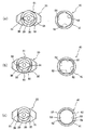
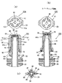
図1〜図3はこの発明の流体容器用注出装置の一実施の形態にかかり、図1(a),(b)はそれぞれ注出ノズルにカバーキャップを被せた状態の縦断面図および平面図で、(a)は切り取り前の状態を、(b)は切り取り後の状態を示す、図2は注出ノズルの左半分のみを切断した縦断面図、平面図および底面図、図3はカバーキャップの直交する2方向の縦断面図、平面図、底面図およびD‐D断面図である。
Hereinafter, embodiments of the present invention will be described in detail with reference to the drawings.
1 to 3 relate to an embodiment of a fluid container pouring device according to the present invention, and FIGS. 1 (a) and 1 (b) are respectively a longitudinal sectional view and a plan view of the pouring nozzle covered with a cover cap. In the figure, (a) shows a state before cutting, (b) shows a state after cutting, FIG. 2 shows a longitudinal sectional view, a plan view, a bottom view, and FIG. It is the longitudinal cross-sectional view of 2 directions which a cover cap orthogonally crosses, a top view, a bottom view, and DD sectional drawing.
この流体容器用注出装置10は、注出ノズル20とカバーキャップ40とを備えて構成され、注出ノズル20は、図示しないパウチなどの流体用容器に基端部が取り付けられるとともに、先端部に切り取り可能な切り取り部を介して開口部材が一体に設けられる。一方、カバーキャップ40は、容器に取り付けられた注出ノズル20に被嵌されるとともに、前記開口部材と係合させ外側からの回転力を介して前記開口部材を切り取ることができるようになっている。
The fluid
この流体容器用注出装置10の注出ノズル20は、図1および図2に示すように、基端部に搬送および容器口部連結のためのガイドとなる基部フランジ部21を備え、平面形状が横長の略八角形状とされ、この基部フランジ部21の容器内側に中央部が円弧状に外側に突き出し左右が尖った横長の略ひし形状の連結部22が設けられており、パウチなどの流体容器の口部と連結部22とが溶着などで固定できるようになっている。
As shown in FIG. 1 and FIG. 2, the dispensing
この注出ノズル20の基部フランジ部21の容器外側部分には、中央部に突き出すように略円筒状の注出ノズル本体23が一体に形成され、中間部に2つのフランジ部24、25が設けてある。
A substantially cylindrical pouring
これら中間部のフランジ部24,25のうち、上方のフランジ部25より上方に突き出す注出ノズル本体23部分が開口後のカテーテルやチューブの接続部26とされて先端部が円錐状に細めてあり、この接続部26に切り取り用の切り取り部27を介して切り取るための開口部材28が一体に成形してある。
Of these
この開口部材28は、注出ノズル本体23の接続部26の上部の円板部29の両側に突き出して切取操作用の操作部30が形成され、これら操作部30を中心軸回りに回動したり、下側から押し上げるようにしたり、これら回動および押し上げを組み合わせることなどで、切り取り部27から切り離して注出ノズル20の先端を開口することができるようになっている。
The opening
一方、このような注出ノズル20に被せられるカバーキャップ40は、図1および図3に示すように、注出ノズル本体23の上方のフランジ部25に当てられる略円筒状のカバーキャップ本体41を備えるとともに、その上部に開口部材28の操作部30の外側を囲むように配置される2つの対向する横断面コ字状の外筒部42とこれらと隣接する2つの円錐部43とが設けられて注出ノズル20の外側を覆うことができるように形成してある。
On the other hand, as shown in FIGS. 1 and 3, the
そして、カバーキャップ40の上面は、棒状の押え部材44が外筒部42の上端同士を連結するブリッジ状に設けてあり、切り取り前のカバーキャップ40を被せた状態では開口部材28の操作部30の上に平行に配置されるようになっている。
The upper surface of the
また、このカバーキャップ40には、切り取り操作のため回動するが、回動を容易にするためカバーキャップ本体41の外側に指掛け用リブ41aが外側に突き出して2箇所設けてある。なお、指掛け用リブ41aは、必要に応じてさらに増設するようにしても良い。
Further, the
このような注出ノズル20とこれに被せるカバーキャップ40とで構成される流体容器用注出装置10では、注出ノズル20の切り取り部27を介して設けられる開口部材28を、カバーキャップ40を回動することで切り取って開口するため、切り離し用カム機構45が設けてある。
In the fluid
この切り離し用カム機構45は、カバーキャップ40の円錐部43の内側に中央部が高く両側が傾斜した切り離しカム46が対向して設けられ、開口部材28の操作部30の下面をカムフォロアとし、カバーキャップ40をその中心軸回りに回動することで、操作部30を押し上げるようにし、これによって開口部材28を切り取り部27から切り離すことができる。
The
この切り離し操作の際、開口部材28の操作部30の下面が切り離しカム46で押さえられるとともに、上面がブリッジ状の押え部材44で押さえられ、切り取られた開口部材28を切り離しカム46と押え部材44とで挟んだ状態にする切り取り片保持手段47が構成され、この切り取り片保持手段47によりカバーキャップ40内に切り取り片(開口部材28)を保持することができ、カバーキャップ40とともに取り除くことができる。
During the separation operation, the lower surface of the
このような開口部材28をカバーキャップ40の回動により切り離しカム46で押し上げて切り取るようにする場合に、注出ノズル20とカバーキャップ40との間に相対回転が生じると、開口が生じる恐れがあることから、この回動を防止する回動防止手段50が設けてある。
When such an
この注出ノズル20とカバーキャップ40との回動防止手段50は、注出ノズル20の上方の円板状のフランジ部25の中心軸を挟んで対向する2箇所に平面で切り欠いたノズル平面部51を形成する一方、カバーキャップ40の対応するカバーキャップ本体41の内側に突き出すように2箇所のキャップ平面部52を形成してある。そして、開口操作前には、ノズル平面部51とキャップ平面部52とが面接触して簡単にはカバーキャップ40を回動できないようにし、開口しようとする力を加えた場合には、カバーキャップ40の弾性変形でノズル平面部51を乗越えて回動できるようにしてある。
The rotation preventing means 50 between the pouring
このようなノズル平面部51とキャップ平面部52を設けることで、注出ノズル20とカバーキャップ40を組み立てる場合の位置合わせに利用することができ、カバーキャップ40の円錐部43および押え部材44の形状配置と協働し、目印として組立作業を容易にすることができる。
By providing such a nozzle
なお、この回動防止手段50として設けるノズル平面部51とキャップ平面部52は、図2および図3に示すように、対向する2箇所に形成する場合のほか、図4(a)に示すように、円周等間隔に3箇所としたり、同図(b)に示すように、4箇所とするようにしても良く、さらに増加するようにしても良い。
The nozzle
さらに、回動防止手段50として機能するカバーキャップ40のキャップ平面部52は連続する直線で構成したものに限定されず、例えば図4(c)に示すように、曲面部53の両端部にキャップ平面部52を有するものでも良く、この場合の平面部も円周等間隔に2箇所とする場合だけでなくさらに増大するようにしても良い。
Furthermore, the cap
このような流体容器用注出装置10では、カバーキャップ40の相対回転を防止する必要のほか、カバーキャップ40が開口操作完了まで軸方向に外れないようにする必要があり、外れ防止手段60が設けてある。
In such a fluid
このカバーキャップ40の外れ防止手段60は、注出ノズル20の上方のフランジ部25を利用し、その下面にカバーキャップ40のカバーキャップ本体41の下端部内側に突き出す係止突部61を引っ掛けて係止するようにして外れを防止する一方、このフランジ部25に形成した回動防止手段50のノズル平面部51の分だけ外周が切り欠かれていることで、係止突部61が引っ掛からないようにして係止を開放できるようにしてある。
The disengagement prevention means 60 of the
なお、ノズル平面部51を設けていない場合には、カバーキャップ本体41を弾性変形させて引き上げるようにして係止を開放することもできる。
When the nozzle
一方、この外れ防止手段60では、カバーキャップ40を注出ノズル20に被せた状態では、係止突部61が上方のフランジ部25のノズル平面部51以外に位置して係止状態とすることができ、カバーキャップ40を回動して開口部材28を切り離し用カム46で切り離して切り離しが完了した状態では、ノズル平面部51に係止突部61が位置して開放状態にすることができるようにしてある。
On the other hand, in this disengagement prevention means 60, when the
このように、回動防止手段50のノズル平面部51をカバーキャップ40の回動防止に用いると同時に、カバーキャップ40の外れ防止手段60の係止突部61の係止開放に用いるようにして兼用し、これにより、構造を簡素化し、製造も容易にできるようにしている。
As described above, the nozzle
さらに、この流体容器用注出装置10では、カバーキャップ40を回動することで注出ノズル20の開口部材28を切り離して開口が完了した状態で、カバーキャップ40の外れ防止手段60の係止が開放されるが、このことを明確に知り、カバーキャップ40を取り外すことができるようにするため、カバーキャップ取り外しカム機構70が設けてあり、切り取り完了後、カバーキャップ40をその中心軸方向外側に移動するようにしてある。
Furthermore, in this fluid
このカバーキャップ取り外しカム機構70は、カバーキャップ40の下部内周に下方に突き出した取り外しカム71が中心軸を挟んで1対形成され、これら取り外しカム71に対応するカムフォロア72が注出ノズル20の上方のフランジ部25の上面2箇所に突き出して形成してある。
In this cover cap
これら取り外しカム71とカムフォロア72とで、カバーキャップ40を回動することで、カバーキャップ40を軸方向外側に押し上げるようにリフトアップすることができる。
By rotating the
これにより、カバーキャップ40を注出ノズル20から取り外して良いことがわかるとともに、カバーキャップ40の外れ防止手段60の係止が開放されていることもわかる。
Accordingly, it can be seen that the
なお、カバーキャップ40の外れ防止手段60として、係止突部61だけを設けノズル平面部51が設けてない場合には、回動位置によってノズル平面部51での開放が起こらないが、カバーキャップ40の取り外しカム71によってリフトアップさせることで、係止突部61を弾性変形させて係止を開放することもできる。
When only the locking
このように構成した流体容器用注出装置10では、図示しない流体容器、例えばパウチの口部に溶着などで取り付けた注出ノズル20に、図1(a)に示すように、カバーキャップ40を被せるようにし、外れ防止手段60の係止突部61を回動防止手段50のノズル平面部51以外のフランジ部25に引っ掛けて係止して取り付けておく。
In the fluid
これにより、カバーキャップ40は注出ノズル20から外れることなく保持され、注出ノズル20を衛生的に保つことができる。
Thereby, the
また、この状態では、注出ノズル20の注出ノズル本体23の先端部に切り取り部27を介して一体に設けてある開口部材28の円板部29および操作部30がカバーキャップ40の外筒部42および円錐部43で取り囲まれた状態となるとともに、開口部材28の上面と注出ノズル本体23の押え部材44とが僅かな隙間を隔てた状態になっている。
Further, in this state, the
さらに、回動防止機構50を構成する注出ノズル20のノズル平面部51とカバーキャップ40のキャップ平面部52とが面接触した状態となり、僅かな力がカバーキャップ40に加わる程度では、カバーキャップ40が回動できず、不用意に開口部材28が切り取られることが防止される。
Further, the nozzle
また、切り離し用カム機構45の切り離しカム46は、開口部材28の操作部30から回転方向で90度離れたところに位置するとともに、キャップ取り外しカム機構70の取り外しカム71は、押し上げ前の状態で注出ノズル20のフランジ部25のカムフォロア72と対向し、あるいは接する状態となっている。
Further, the
次に、流体容器内の内容物(流体)を取り出す場合には、カバーキャップ40の指掛け用リブ41aに指を掛けるなどし、カバーキャップ40をその中心軸回りに回動するように注出ノズル20の外側に沿って回動する。
このとき、回動防止機構50を構成する注出ノズル20のノズル平面部51とカバーキャップ40のキャップ平面部52とが面接触した状態となっているので、カバーキャップ40を弾性変形させノズル平面部51を乗越えるようにして回動防止機構50を開放させる。
Next, when taking out the contents (fluid) in the fluid container, a finger is put on the finger-hanging
At this time, since the nozzle
このカバーキャップ40の回動により、切り離し用カム機構45の切り離しカム46が、まず開口部材28の両側の操作部30の下側に入り込み、この後操作部30の下面との接触が始まり、さらに回動されると、図1(b)に示すように、操作部30が両側で押し上げられて切り取り部27から切り取られる。
By the rotation of the
そして、切り取られた開口部材28は、切り取り片保持手段47を構成するカバーキャップ本体41の押え部材44および切り離しカム46で上下が挟まれ、カバーキャップ40内に確実に保持された状態となる。
The
また、カバーキャップ40の回動により、切り離し用カム機構45の切り離しカム46が開口部材28の両側の操作部30の下側に入り込んだ後、キャップ取り外しカム機構70の取り外しカム71とカムフォロア72との接触が開始されてカバーキャップ40が押し上げられるようになり、開口部材28が切り取られた状態になると、注出ノズル20のフランジ部25からリフトアップされた状態となる。これと同時に、カバーキャップ40の外れ防止機構60の係止突部61がカバーキャップ40のリフトアップによる弾性変形とノズル平面部51に位置することで係止が開放される。
Further, after the
これらにより、カバーキャップ40が注出ノズル20のフランジ部25からリフトアップされた状態では、開口部材28の切り取りが完了し、カバーキャップ40の外れ防止機構60が開放されていることを簡単に知ることができ、注出ノズル20からカバーキャップ40を取り外して良いことが分かる。
Thus, in a state where the
この後、カバーキャップ40を取り外すことで、切り取られた開口部材28もカバーキャップ40内に保持した状態で取り除くことができる。
これにより、注出ノズル20の接続部26に直接手を触れずに開口することができ、衛生的であり、直ちにチューブなどの接続を行うことができる。なお、切り離しは、切り離し用カム機構45を使用せずに、キャップ取り外し用カム機構70のみを使用して行うこともできる。
Thereafter, by removing the
Thereby, it can open without touching the
以上のように、この流体容器用注出装置10によれば、簡単な構造で、カバーキャップの回動防止、カバーキャップの外れ防止、切り取り片の保持および一体廃棄など必要な機能をすべて備えることができるとともに、衛生的に取り扱うことができる。
As described above, according to the fluid
次に、この発明の他の一実施の形態を、図5〜図7により説明するが、すでに説明した実施の形態と同一部分には同一記号を記し、説明は省略する。
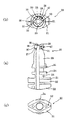
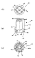
図5〜図7はこの発明の流体容器用注出装置の他の一実施の形態にかかり、図5(a),(b),(c)はそれぞれ注出ノズルにカバーキャップを被せた状態の縦断面図,平面図およびC−C断面図で、(a)、(c)は切り取り前の状態を、(b)は切り取り後の状態を示す、図6は注出ノズルの左半分のみを切断した縦断面図、平面図および底面図、図7はカバーキャップのA−O−A断面図、平面図および底面図である。
Next, another embodiment of the present invention will be described with reference to FIGS. 5 to 7. The same reference numerals are given to the same parts as those of the embodiment already described, and the description will be omitted.
5 to 7 show another embodiment of the fluid container pouring device according to the present invention. FIGS. 5 (a), 5 (b), and 5 (c) show a state in which the pouring nozzle is covered with a cover cap. (A), (c) shows a state before cutting, (b) shows a state after cutting, and FIG. 6 shows only the left half of the dispensing nozzle. FIG. 7 is a cross-sectional view, a plan view, and a bottom view of the cover cap taken along line A-O-A.
この流体容器用注出ノズル10Aでは、注出ノズル20の開口部材28をカバーキャップ40の回動操作による回転だけで切り離すようにしたものであり、押し上げ力を加えずに切り離すようにしている。
In the fluid
したがって、この流体容器用注出装置10Aの注出ノズル20の切り取り部27を介して一体に形成される開口部材28には、円板部29の周囲に4箇所の操作部30が突き出して形成してある。
Accordingly, the
また、開口部材28の円板部29の外側面には、切り取り片保持手段47を構成する水平の凸条31が形成してあり、上面には、カバーキャップ40を支持する円形に窪んだ支持部32が形成してある。
Further, a
一方、カバーキャップ40には、開口部材28の円板部29および操作部30が嵌合される嵌合凹部48がこれらの平面形状に対応して形成されるとともに、この嵌合凹部48の内面に開口部材28の水平の凸条31に対応する凹溝49が形成され、凸条31と凹溝49とを係合することで、切り取られた開口部材28をカバーキャップ40内に保持する切り取り片保持手段47を構成している。
On the other hand, the
また、カバーキャップ40のカバーキャップ本体41の天面内側に下方に突き出す支持突起41bが形成してあり、開口部材28の支持部32と係合するようになっている。
In addition, a
なお、この流体容器用注出装置10Aの他の構成は、すでに説明した流体容器用注出装置10と同一であり、同一の構成の回動防止手段50、外れ防止手段60、キャップ取り外しカム機構70を備えている。
The other configuration of the fluid
このように構成した流体容器用注出装置10Aでは、図示しない流体容器、例えばパウチの口部に溶着などで取り付けた注出ノズル20に、図5(a)に示すように、カバーキャップ40を被せるようにし、外れ防止手段60の係止突部61を回動防止手段50のノズル平面部51以外のフランジ部25に引っ掛けて係止して取り付けておく。
これにより、カバーキャップ40は注出ノズル20から外れることなく保持され、注出ノズル20を衛生的に保つことができる。
In the fluid
Thereby, the
また、この状態では、注出ノズル20の注出ノズル本体23の先端部に切り取り部27を介して一体に設けてある開口部材28の円板部29および操作部30がカバーキャップ40の嵌合凹部48に嵌合されるとともに、開口部材28の凸条31とカバーキャップ40の凹溝49が係合し、開口部材28が切り取られてもカバーキャップ40に確実に保持できる状態になっている。
Further, in this state, the
さらに、回動防止機構50を構成する注出ノズル20のノズル平面部51とカバーキャップ40のキャップ平面部52とが面接触した状態となり、僅かな力がカバーキャップ40に加わる程度では、カバーキャップ40が回動できず、開口部材28の切り取り部27の強度による回動を防止する機能と協働して一層確実に不用意に開口部材28が切り取られることが防止される。
Further, the nozzle
また、カバーキャップ40のカバーキャップ本体41の天面内側の支持突起41bが注出ノズル20の開口部材28の上面の窪んだ支持部32と係合し、これらを中心にカバーキャップ40を回動できるようになっている。
Further, the
さらに、キャップ取り外しカム機構70の取り外しカム71は、押し上げ前の状態で注出ノズル20のフランジ部25のカムフォロア72と隙間をあけて対向し、あるいは接する状態となっている。
Further, the
次に、流体容器内の内容物(流体)を取り出す場合には、カバーキャップ40の指掛け用リブ41aに指を掛けるなどし、カバーキャップ40をその中心軸回りに回動するように注出ノズル20の外周面に沿って回動する。
このとき、回動防止機構50を構成する注出ノズル20のノズル平面部51とカバーキャップ40のキャップ平面部52とが面接触した状態となっているので、カバーキャップ40を弾性変形させノズル平面部51を乗越えるようにして回動防止機構50を開放させる。
Next, when taking out the contents (fluid) in the fluid container, a finger is put on the finger-hanging
At this time, since the nozzle
このカバーキャップ40を回動する場合に、注出ノズル20の支持部32とカバーキャップ40の支持突起41bとの係合により、カバーキャップ40を注出ノズル20に対して安定して回動させることができる。
When the
また、この流体容器用注出装置10Aでは、カバーキャップ40の回動で、カバーキャップ40の嵌合凹部48に嵌合している開口部材28が回動されて切り取り部27から切り取られ、注出ノズル20が開口される。
In addition, in this fluid
そして、切り取られた開口部材28は、切り取り片保持手段47を構成するカバーキャップ本体41の凹溝49と開口部材28の凸条31との係合によってカバーキャップ40内に確実に保持された状態となる。
The
また、カバーキャップ40の回動により、キャップ取り外しカム機構70の取り外しカム71とカムフォロア72との接触が開始されてカバーキャップ40が押し上げられるようになり、開口部材28が切り取られた状態になると、注出ノズル20のフランジ部25からリフトアップされた状態となる。これと同時に、カバーキャップ40の外れ防止機構60の係止突部61がカバーキャップ40のリフトアップによる弾性変形とノズル平面部51に位置することで係止が開放される。
Further, when the
これらにより、カバーキャップ40が注出ノズル20のフランジ部25からリフトアップされた状態では、開口部材28の切り取りが完了し、カバーキャップ40の外れ防止機構60が開放されていることを簡単に知ることができ、注出ノズル20からカバーキャップ40を取り外して良いことが分かる。
Thus, in a state where the
この後、カバーキャップ40を取り外すことで、切り取られた開口部材28もカバーキャップ40内に保持した状態で取り除くことができ、一体として廃棄することができる。
Thereafter, by removing the
これにより、注出ノズル20の接続部26に直接手を触れずに開口することができ、衛生的であり、直ちにチューブなどの接続を行うことができる。
Thereby, it can open, without touching the
以上のように、この流体容器用注出装置10Aによれば、簡単な構造で、カバーキャップの回動防止、カバーキャップの外れ防止、切り取り片の保持および一体廃棄など必要な機能をすべて備えることができるとともに、衛生的に取り扱うことができる。
As described above, according to the fluid
なお、上記実施の形態では、流体容器の材質や形状については、特に説明していないが、通常の流体用の容器として用いられるものであれば良く、特に合成樹脂製のバッグ状やボトル状のもので、医療用の経腸栄養剤や流動食あるいは点滴用などの薬液が入れられる容器等に好適である。 In the above embodiment, the material and shape of the fluid container are not particularly described, but any material can be used as long as it is used as a normal fluid container. Therefore, it is suitable for a container for storing a medical enteral nutrient, a liquid food, or a drug solution for infusion.
また、注出装置を構成する注出ノズルやカバーキャップの材質は、特に説明していないが、通常用いられる合成樹脂で良く、例えばポリプロピレンなどが用いられ、射出成形などで成形される。 The material of the pouring nozzle and the cover cap constituting the pouring device is not particularly described, but may be a commonly used synthetic resin, such as polypropylene, which is molded by injection molding or the like.
10,10A 流体容器用注出装置
20 注出ノズル
21 基部フランジ部
22 連結部
23 注出ノズル本体
24,25 フランジ部
26 接続部
27 切り取り部
28 開口部材
29 円板部
30 操作部
31 凸条
32 支持部
40 カバーキャップ
41 カバーキャップ本体
41a 指掛け用リブ
41b 支持突起
42 外筒部
43 円錐部
44 押え部材
45 切り離し用カム機構
46 切り離しカム
47 切り取り片保持手段
48 嵌合凹部
49 凹溝
50 回動防止手段
51 ノズル平面部
52 キャップ平面部
53 曲面部
60 外れ防止手段
61 係止突部
70 カバーキャップ取り外しカム機構
71 取り外しカム
72 カムフォロア
10, 10A Fluid
Claims (7)
前記注出ノズルと前記カバーキャップとの間に、切り取り操作前の相対回転による前記開口部材の切り取りを防止する回動防止手段を設け、
この回動防止手段を、前記注出ノズルと前記カバーキャップとに設けた円筒部同士で嵌合させ、前記注出ノズルの円筒外側面に少なくとも1つのノズル平面部を形成し、このノズル平面部と当接して回転を規制するとともに、乗越えて回動を可能とするキャップ平面部を前記カバーキャップの円筒内側面に形成して構成したことを特徴とする流体容器用注出装置。 A base end portion is attached to the fluid container, and a pouring nozzle in which an opening member is integrally provided at a distal end portion through a cut-out portion, and is fitted to the pouring nozzle and is engaged with the opening member. A fluid container pouring device comprising a cover cap capable of cutting off the opening member via a rotational force from the outside,
Provided between the dispensing nozzle and the cover cap is a rotation preventing means for preventing the opening member from being cut by relative rotation before the cutting operation ,
The rotation preventing means is fitted between cylindrical portions provided on the extraction nozzle and the cover cap, and at least one nozzle plane portion is formed on the cylindrical outer surface of the extraction nozzle. A fluid container pouring device comprising: a cap flat surface portion formed on the inner surface of the cylinder of the cover cap, wherein the cap flat surface portion is allowed to come into contact with the inner surface of the cover cap and rotate .
この外れ防止手段を、前記注出ノズルの前記円筒部の平面部以外に係止可能とされるとともに、前記円筒部の平面部で係止開放可能な係止突部を前記カバーキャップに形成して構成したことを特徴とする請求項1記載の流体容器用注出装置。 A disengagement prevention means is provided to prevent the disengagement in the axial direction by holding the fitted state between the dispensing nozzle and the cover cap,
The disengagement prevention means can be locked to a portion other than the flat portion of the cylindrical portion of the dispensing nozzle, and a locking protrusion that can be locked and released by the flat portion of the cylindrical portion is formed on the cover cap. The fluid container dispensing apparatus according to claim 1, wherein the fluid container dispensing apparatus is configured as described above.
Claims wherein the cut piece holding means, and the pressing member for pressing the upper surface of the opening member provided on the cover cap, characterized by being configured so as to sandwich at the cam of the disconnecting cam mechanism of claim 4, wherein Item 6. A fluid container pouring device according to Item 5 .
Priority Applications (1)
| Application Number | Priority Date | Filing Date | Title |
|---|---|---|---|
| JP2004208869A JP4635497B2 (en) | 2004-07-15 | 2004-07-15 | Liquid container dispensing device |
Applications Claiming Priority (1)
| Application Number | Priority Date | Filing Date | Title |
|---|---|---|---|
| JP2004208869A JP4635497B2 (en) | 2004-07-15 | 2004-07-15 | Liquid container dispensing device |
Related Child Applications (1)
| Application Number | Title | Priority Date | Filing Date |
|---|---|---|---|
| JP2010121405A Division JP5177583B2 (en) | 2010-05-27 | 2010-05-27 | Liquid container dispensing device |
Publications (2)
| Publication Number | Publication Date |
|---|---|
| JP2006027662A JP2006027662A (en) | 2006-02-02 |
| JP4635497B2 true JP4635497B2 (en) | 2011-02-23 |
Family
ID=35894479
Family Applications (1)
| Application Number | Title | Priority Date | Filing Date |
|---|---|---|---|
| JP2004208869A Expired - Fee Related JP4635497B2 (en) | 2004-07-15 | 2004-07-15 | Liquid container dispensing device |
Country Status (1)
| Country | Link |
|---|---|
| JP (1) | JP4635497B2 (en) |
Families Citing this family (17)
| Publication number | Priority date | Publication date | Assignee | Title |
|---|---|---|---|---|
| JP4857956B2 (en) * | 2006-06-29 | 2012-01-18 | 大日本印刷株式会社 | Outlet with protective cap |
| JP4858000B2 (en) * | 2006-08-07 | 2012-01-18 | 大日本印刷株式会社 | Outlet with protective cap |
| JP4873367B2 (en) * | 2006-11-07 | 2012-02-08 | 東洋製罐株式会社 | Twist opening mechanism for containers |
| JP4985223B2 (en) * | 2007-08-22 | 2012-07-25 | 東洋製罐株式会社 | Twist opening mechanism for containers |
| JP4987661B2 (en) | 2007-10-19 | 2012-07-25 | 東洋製罐株式会社 | Extraction material |
| WO2010095273A1 (en) * | 2009-02-19 | 2010-08-26 | 東洋製罐株式会社 | Twist-cut unsealing mechanism for container |
| JP5604691B2 (en) * | 2010-03-29 | 2014-10-15 | 株式会社フジシール | Outlet |
| EP3471550A4 (en) | 2016-06-16 | 2020-02-26 | Sigma Phase, Corp. | SYSTEM FOR PROVIDING A SINGLE PORTION OF FROZEN CONFECTIONERY |
| JP6892350B2 (en) * | 2017-08-02 | 2021-06-23 | 日本クロージャー株式会社 | Cut-off spout |
| JP6959069B2 (en) * | 2017-08-23 | 2021-11-02 | 日本クロージャー株式会社 | Cut-off spout |
| JP6989331B2 (en) * | 2017-09-29 | 2022-01-05 | 日本クロージャー株式会社 | Cut-off spout |
| US10612835B2 (en) | 2018-08-17 | 2020-04-07 | Sigma Phase, Corp. | Rapidly cooling food and drinks |
| US11470855B2 (en) | 2018-08-17 | 2022-10-18 | Coldsnap, Corp. | Providing single servings of cooled foods and drinks |
| US10543978B1 (en) | 2018-08-17 | 2020-01-28 | Sigma Phase, Corp. | Rapidly cooling food and drinks |
| US11337438B2 (en) | 2020-01-15 | 2022-05-24 | Coldsnap, Corp. | Rapidly cooling food and drinks |
| TW202202790A (en) | 2020-06-01 | 2022-01-16 | 美商寇德斯納普公司 | Refrigeration systems for rapidly cooling food and drinks |
| US11827402B2 (en) | 2021-02-02 | 2023-11-28 | Coldsnap, Corp. | Filling aluminum cans aseptically |
Family Cites Families (4)
| Publication number | Priority date | Publication date | Assignee | Title |
|---|---|---|---|---|
| FR2653746A1 (en) * | 1989-10-26 | 1991-05-03 | Merck Sharp & Dohme | STERILE PACKAGING ASSEMBLY FOR DISPENSING LIQUID, AND METHOD FOR MANUFACTURING SUCH A ASSEMBLY. |
| JP2605789Y2 (en) * | 1993-12-24 | 2000-08-07 | 株式会社吉野工業所 | Liquid storage container |
| JP2001278323A (en) * | 2000-04-04 | 2001-10-10 | Takeuchi Press Ind Co Ltd | Tube container |
| JP2002293361A (en) * | 2001-03-30 | 2002-10-09 | Gomuno Inaki Kk | Container capper |
-
2004
- 2004-07-15 JP JP2004208869A patent/JP4635497B2/en not_active Expired - Fee Related
Also Published As
| Publication number | Publication date |
|---|---|
| JP2006027662A (en) | 2006-02-02 |
Similar Documents
| Publication | Publication Date | Title |
|---|---|---|
| JP4635497B2 (en) | Liquid container dispensing device | |
| JP6310855B2 (en) | package | |
| JP4987661B2 (en) | Extraction material | |
| CA2834152C (en) | Reconstitution device | |
| JP6438767B2 (en) | package | |
| US8646634B2 (en) | Screw cap and a sport closure cap with integral inner seal opening means | |
| CN209154515U (en) | Connector, the medical package object including the connector and the diaphragm for connector | |
| JP6602233B2 (en) | Hinge cap | |
| CN107106410A (en) | Connector system with least two conveying ends | |
| CN101605700A (en) | Bottles for receiving defined doses of liquids | |
| JP4706276B2 (en) | Liquid container dispensing device | |
| US8651305B1 (en) | Reclosable container closure | |
| JP5177583B2 (en) | Liquid container dispensing device | |
| TW201637952A (en) | A cap for a container and a package comprising such a container | |
| RU2524637C2 (en) | Medical connector and its bendable combined lid | |
| EP1122185B1 (en) | Cap for container | |
| KR102356558B1 (en) | Cap for accepting the drug of the beverage bottle | |
| JP4531516B2 (en) | Container lid | |
| JP2012030821A (en) | Hinge cap | |
| JP2004299760A (en) | Container lid containing auxiliary member storing auxiliary substance | |
| WO2017100829A1 (en) | Lid for container | |
| JP3124569U (en) | Container plug device | |
| JP6523008B2 (en) | Container spout | |
| JP2002347797A (en) | Cap of container | |
| JP4404253B2 (en) | Simple open container lid |
Legal Events
| Date | Code | Title | Description |
|---|---|---|---|
| A621 | Written request for application examination |
Free format text: JAPANESE INTERMEDIATE CODE: A621 Effective date: 20070608 |
|
| A977 | Report on retrieval |
Free format text: JAPANESE INTERMEDIATE CODE: A971007 Effective date: 20100304 |
|
| A131 | Notification of reasons for refusal |
Free format text: JAPANESE INTERMEDIATE CODE: A131 Effective date: 20100401 |
|
| A521 | Request for written amendment filed |
Free format text: JAPANESE INTERMEDIATE CODE: A523 Effective date: 20100527 |
|
| TRDD | Decision of grant or rejection written | ||
| A01 | Written decision to grant a patent or to grant a registration (utility model) |
Free format text: JAPANESE INTERMEDIATE CODE: A01 Effective date: 20101026 |
|
| A01 | Written decision to grant a patent or to grant a registration (utility model) |
Free format text: JAPANESE INTERMEDIATE CODE: A01 |
|
| A61 | First payment of annual fees (during grant procedure) |
Free format text: JAPANESE INTERMEDIATE CODE: A61 Effective date: 20101108 |
|
| FPAY | Renewal fee payment (event date is renewal date of database) |
Free format text: PAYMENT UNTIL: 20131203 Year of fee payment: 3 |
|
| R150 | Certificate of patent or registration of utility model |
Ref document number: 4635497 Country of ref document: JP Free format text: JAPANESE INTERMEDIATE CODE: R150 Free format text: JAPANESE INTERMEDIATE CODE: R150 |
|
| FPAY | Renewal fee payment (event date is renewal date of database) |
Free format text: PAYMENT UNTIL: 20131203 Year of fee payment: 3 |
|
| S531 | Written request for registration of change of domicile |
Free format text: JAPANESE INTERMEDIATE CODE: R313531 |
|
| FPAY | Renewal fee payment (event date is renewal date of database) |
Free format text: PAYMENT UNTIL: 20131203 Year of fee payment: 3 |
|
| R350 | Written notification of registration of transfer |
Free format text: JAPANESE INTERMEDIATE CODE: R350 |
|
| S533 | Written request for registration of change of name |
Free format text: JAPANESE INTERMEDIATE CODE: R313533 |
|
| FPAY | Renewal fee payment (event date is renewal date of database) |
Free format text: PAYMENT UNTIL: 20131203 Year of fee payment: 3 |
|
| R350 | Written notification of registration of transfer |
Free format text: JAPANESE INTERMEDIATE CODE: R350 |
|
| S111 | Request for change of ownership or part of ownership |
Free format text: JAPANESE INTERMEDIATE CODE: R313111 |
|
| R350 | Written notification of registration of transfer |
Free format text: JAPANESE INTERMEDIATE CODE: R350 |
|
| LAPS | Cancellation because of no payment of annual fees |