JP4635442B2 - Battery pack - Google Patents
Battery pack Download PDFInfo
- Publication number
- JP4635442B2 JP4635442B2 JP2004011654A JP2004011654A JP4635442B2 JP 4635442 B2 JP4635442 B2 JP 4635442B2 JP 2004011654 A JP2004011654 A JP 2004011654A JP 2004011654 A JP2004011654 A JP 2004011654A JP 4635442 B2 JP4635442 B2 JP 4635442B2
- Authority
- JP
- Japan
- Prior art keywords
- battery
- secondary battery
- pack
- battery pack
- plate
- Prior art date
- Legal status (The legal status is an assumption and is not a legal conclusion. Google has not performed a legal analysis and makes no representation as to the accuracy of the status listed.)
- Expired - Fee Related
Links
Images


Classifications
-
- Y—GENERAL TAGGING OF NEW TECHNOLOGICAL DEVELOPMENTS; GENERAL TAGGING OF CROSS-SECTIONAL TECHNOLOGIES SPANNING OVER SEVERAL SECTIONS OF THE IPC; TECHNICAL SUBJECTS COVERED BY FORMER USPC CROSS-REFERENCE ART COLLECTIONS [XRACs] AND DIGESTS
- Y02—TECHNOLOGIES OR APPLICATIONS FOR MITIGATION OR ADAPTATION AGAINST CLIMATE CHANGE
- Y02E—REDUCTION OF GREENHOUSE GAS [GHG] EMISSIONS, RELATED TO ENERGY GENERATION, TRANSMISSION OR DISTRIBUTION
- Y02E60/00—Enabling technologies; Technologies with a potential or indirect contribution to GHG emissions mitigation
- Y02E60/10—Energy storage using batteries
Landscapes
- Secondary Cells (AREA)
- Portable Power Tools In General (AREA)
Description
本発明は、電動ドリルなどの電動工具の電池電源として好適な電池パックに関するものである。 The present invention relates to a battery pack suitable as a battery power source for an electric tool such as an electric drill.
電動工具のハイパワー化に伴ってその電池電源として構成された電池パックは大きな放電電力が出力できるものが要求される。この要求を満たすために多数の二次電池をパックケース内に収めた電池パックが用いられている。多数の二次電池を樹脂製のパックケース内に収容すると、充放電にともなって二次電池から発生する熱は外部に放散され難いため内部にこもりがちになる。また、他の二次電池に囲まれた中央部分に位置する二次電池は放熱が妨げられると同時に周囲の二次電池の発熱の影響を受け、温度上昇が激しくなり電池性能のバラツキや劣化を生じる原因となる。 A battery pack configured as a battery power source with a high power of an electric tool is required to output a large discharge power. In order to satisfy this requirement, a battery pack in which a large number of secondary batteries are housed in a pack case is used. When a large number of secondary batteries are accommodated in a pack case made of resin, heat generated from the secondary batteries due to charge / discharge is not easily dissipated to the outside, and the interior tends to remain inside. In addition, the secondary battery located in the center surrounded by other secondary batteries is prevented from dissipating heat and at the same time affected by the heat generated by the surrounding secondary batteries, resulting in a significant increase in temperature, resulting in variations and deterioration in battery performance. Cause.
多数の二次電池をパックケース内に収容した電池パックでは放熱構造を備えることが不可欠であり、様々な放熱構造を設けた電池パックが提案されている。例えば、積層配置された二次電池の間に熱伝導性のよい金属板を介在させ、この金属板に加熱部を嵌め込んだヒートパイプの放熱部をパックケースの一部を形成する放熱部材に連結し、各二次電池の熱を放熱部材から外部に放散する構造を備えた電池パックが知られている(特許文献1参照)。
上記従来技術はニッケル−水素蓄電池などの水溶液系二次電池に構成された円筒形の二次電池を俵積み状態に集積してパックケース内に収容したもので、全ての二次電池から熱伝導により放熱させ、各二次電池の温度を均等化しようとする構造であるため、熱伝導性のよい金属部材が多く使用されるため電池パックの重量増加や大型化が避けられない。 In the above prior art, cylindrical secondary batteries configured in an aqueous solution type secondary battery such as a nickel-hydrogen storage battery are stacked in a stacked state and accommodated in a pack case. Therefore, the battery pack is inevitably increased in weight and size because a metal member having good thermal conductivity is used in many cases.
電動工具のように操作性が重視される機器の電池電源としては軽量化や小型化が求められており、重量エネルギー密度及び体積エネルギー密度に優れた非水電解液系二次電池を用いて小型軽量化した電池パックが好ましいものとなる。特に、扁平角形の二次電池を用いて電池パックを構成するとスペース効率がよく、電池パックをよりコンパクトに構成することが可能となる。しかし、非水電解液系二次電池は大電流放電を行ったときの発熱が大きく、より確実な放熱構造を構成して二次電池の発熱を抑えると共に多数の二次電池の温度を均等化することが要求される。 Battery power sources for devices that emphasize operability, such as power tools, are required to be lighter and smaller, and small using nonaqueous electrolyte secondary batteries with excellent weight energy density and volumetric energy density. A lightweight battery pack is preferable. In particular, when a battery pack is configured using a flat rectangular secondary battery, space efficiency is good and the battery pack can be configured more compactly. However, non-aqueous electrolyte secondary batteries generate a large amount of heat when a large current is discharged, and a more reliable heat dissipation structure is configured to suppress secondary battery heat generation and equalize the temperature of many secondary batteries. It is required to do.
電気自動車用の電池電源装置では大型の扁平角形電池を並列配置して強制空冷により二次電池を冷却する放熱構造が採用されるが、電池電源を使用する機器や充電器に対して着脱自在とする電池パックのような小型の電池電源装置では強制空冷の構造を適用することが困難であった。 The battery power supply for electric vehicles employs a heat dissipation structure in which large flat rectangular batteries are arranged in parallel and the secondary battery is cooled by forced air cooling, but it is detachable from equipment and chargers that use battery power. In a small battery power supply device such as a battery pack, it is difficult to apply a forced air cooling structure.
本発明が目的とするところは、機器や充電器に対して着脱自在に構成された電池パックに送風ファンを設けて空冷による二次電池の放熱を可能とした電池パックを提供することにある。 An object of the present invention is to provide a battery pack that can dissipate a secondary battery by air cooling by providing a blower fan in a battery pack that is configured to be detachable from a device or a charger.
上記目的を達成するための本発明は、電池缶内に極板群及び電解液を収容して開口端を封口板によって封口し、前記封口板に極端子が設けられてなる複数の二次電池と、各二次電池の動作状態を管理する電池管理回路を構成した回路基板とをパックケース内に収容し、機器及び充電器に対して着脱自在とする着脱部を備えてなる電池パックであって、前記複数の二次電池を所定間隔を隔てて並列保持し、前記着脱部に二次電池の並列配置方向と交差する方向が送風方向となるように送風ファンが配設されて、前記二次電池は、扁平角形に形成され、その最大面積平坦面が所定間隔を隔てて互いに対面するようにフレームによって保持され、さらに、送風空気の流れ方向を調整する整流板が設けられ、前記電池管理回路は、電池温度の検出に基づいて送風ファンの回転を制御し、排気ファンを持つ充電器と接続可能であり、前記排気ファンの排気空気の流れ方向上に、前記送風ファンが配置されることを特徴とする。 In order to achieve the above object, the present invention provides a plurality of secondary batteries in which an electrode plate group and an electrolytic solution are accommodated in a battery can, an opening end is sealed with a sealing plate, and electrode terminals are provided on the sealing plate. And a circuit board that constitutes a battery management circuit that manages the operation state of each secondary battery in a pack case, and is a battery pack that includes a detachable part that is detachable from the device and the charger. Te, the plurality of secondary batteries in parallel and held at a predetermined distance in a direction intersecting the parallel arrangement direction of the secondary battery in the detachable part is the blower fan is disposed such that the airflow direction, the two The secondary battery is formed in a flat rectangular shape, and is held by a frame so that the flat surfaces of the maximum area face each other at a predetermined interval, and further provided with a rectifying plate for adjusting the flow direction of the blown air, the battery management The circuit is based on battery temperature detection. There controls the rotation of the blower fan, it can be connected to charger with an exhaust fan, on the flow direction of the exhaust air of the exhaust fan, wherein the blower fan is disposed.
上記構成によれば、電池パックを機器あるいは充電器に対して着脱自在とするために突出形成された着脱部に送風ファンを配設しているので、小型の電池パックであっても空冷による二次電池の冷却が可能となる。送風ファンからの送風空気は所定間隔を隔てて並列配置された間隔内に流れるので、複数の二次電池を均等に冷却することができる。 According to the above configuration, since the blower fan is disposed in the projecting and detachable portion so as to make the battery pack detachable from the device or the charger, even a small battery pack can be air-cooled. The secondary battery can be cooled. Since the blown air from the blower fan flows in the intervals arranged in parallel at a predetermined interval, the plurality of secondary batteries can be cooled uniformly.
上記構成において、二次電池は扁平角形に形成され、その最大面積平坦面が所定間隔を隔てて互いに対面するようにフレームによって保持することにより、扁平角形の二次電池を所定間隔に並列配置して最大面積平坦面に送風ファンからの送風空気を当てて冷却することができ、スペース効率よく複数の二次電池をパックケース内に収容することができる。 In the above configuration, the secondary battery is formed in a flat rectangular shape, and the flat rectangular secondary batteries are arranged in parallel at a predetermined interval by being held by a frame so that the flat surface of the maximum area faces each other with a predetermined interval. Thus, the air blown from the blower fan can be applied to the flat surface with the maximum area to cool the battery, and a plurality of secondary batteries can be accommodated in the pack case with high space efficiency.
また、送風空気の流れ方向を調整する整流板を設けることにより、複数の二次電池に均等に送風空気を送ることができ、複数の二次電池の温度を均等化することができる。 Moreover, by providing the baffle plate which adjusts the flow direction of blowing air, blowing air can be sent uniformly to several secondary batteries, and the temperature of several secondary batteries can be equalized.
また、電池管理回路は、電池温度の検出に基づいて送風ファンの回転を制御することにより、複数の二次電池を適正な電池温度に維持することができる。 Further, the battery management circuit can maintain the plurality of secondary batteries at an appropriate battery temperature by controlling the rotation of the blower fan based on the detection of the battery temperature.
本発明によれば、小型の電池パックに送風ファンによる冷却構造を設けることが可能となり、送風空気が複数の二次電池に均等に送給されるので、複数の二次電池の電池温度を均等化することができる。 According to the present invention, it becomes possible to provide a cooling structure with a blower fan in a small battery pack, and since the blown air is evenly supplied to the plurality of secondary batteries, the battery temperatures of the plurality of secondary batteries are evenly distributed. Can be
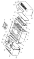
図1は、実施形態に係る電池パック1を示すもので、図9に示すように、電動工具Aに装着して電動工具Aの駆動電源となるように構成されている。また、電動工具Aの使用により電池容量が減少したときには、電動工具Aから取り外し、図10に示すように、充電器Bに装填することにより、充電することができる。電動工具A又は充電器Bへの装着は、パックケース5の上方に設けられた装着部20の両側面に形成された摺動溝20aに電動工具A又は充電器Bに設けられた凸条部が嵌入するように電池パック1を押し込むと、装着部20の中央に保持されたコネクタケース12に設けられた接続プラグ14が電動工具A又は充電器Bのソケットに挿入されて電気的接続がなされると共に電池パック1は装着される。
FIG. 1 shows a battery pack 1 according to the embodiment. As shown in FIG. 9, the battery pack 1 is mounted on the electric power tool A to be a driving power source for the electric power tool A. When the battery capacity decreases due to the use of the electric power tool A, the battery can be charged by being removed from the electric power tool A and loaded in the charger B as shown in FIG. Mounting to the electric power tool A or the charger B is performed on the
この電池パック1は、図2に分解図示するように、パックケース5内に10個の二次電池2と、この二次電池2の充放電制御や電池保護制御などを行う電池管理回路を構成した回路基板3とを収容し、二次電池2の放熱を促す送風ファン4を一体に組み込んで構成されている。
As shown in an exploded view in FIG. 2, the battery pack 1 includes 10
前記二次電池2は、扁平直方体の外形に形成されたリチウムイオン二次電池が適用されており、図2に示すように、この二次電池2の最大面積平坦面がパックケース5の底面に対して垂直方向になり、所定間隔を隔てて互いに対向するようにして、10個の二次電池2が並列配置されている。このように10個の二次電池2を所定間隔を隔てて並列配置された状態に保持するために、図4に示すように、二次電池2の長手方向中央部分の断面積に対応する開口形状寸法の電池収容部(開口部)17を10箇所に形成したセンターフレーム7により二次電池2の中央部分が保持され、二次電池2の両端がそれぞれ端子側フレーム6、底側フレーム8で保持されている。
As the
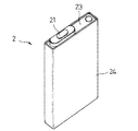
図3に示すように、二次電池2は、有底角筒に形成された電池缶24内に、長尺に形成した正極板と負極板とをセパレータを介して巻回した巻回型極板群、もしくは複数の正極板と負極板とをセパレータを介して積層した積層型極板群を挿入し、電池缶24の開口端に封口板23を溶接して電池缶24の開口端を封口し、電池缶24内に電解液を注入して電池缶24内が密閉される。前記封口板23には正極板に接続した正極端子21が封口板23と電気的に絶縁して設けられ、封口板23及び電池缶24は二次電池2の負極端子を構成する。
As shown in FIG. 3, the
二次電池2は大電流の放電や過充電等の原因により温度上昇すると、熱膨張や電解液の気化などによって電池缶24に膨らみが生じ、それは電池缶24の側面となる最大面積平坦面に顕著に現れる。電池缶24内に収容された極板群は、それが巻回型であっても積層型であっても正極板と負極板とがセパレータを介して積層された状態に電池缶24の両側の最大面積平坦面の間で挟圧され、セパレータに含浸された状態で存在する電解液中を移動するイオンが正極板と負極板との間で行き来することにより充放電反応がなされる。電池缶24に膨らみが生じると、積層間の密着状態が損なわれ、積層間に隙間が発生すると、イオン移動度に不具合が生じ、充放電反応が充分になされない状態となる恐れがある。
When the temperature of the
図4に示すように、センターフレーム7は、10個の二次電池2をそれぞれ電池収納部17に挿入すると、二次電池2をその電池缶24の略中央部分を周囲から囲んだ状態に保持するので、二次電池2は膨らみが生じないように挟圧された状態となる。因みに、本実施形態に適用した二次電池2の短手方向幅は10mmであり、電池収容部17の短手方向幅は10.4mmに形成されているので、組み立て当初では二次電池2を電池収容部17にスムーズに挿入でき、電池缶24の膨らみは電池収容部17の幅で規制されるため、電池缶24の膨らみによる二次電池2の性能低下は抑制される。
As shown in FIG. 4, the
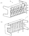
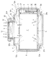
10個の二次電池2はそれぞれを同一方向にしてセンターフレーム7の各電池収容部17に挿入され、二次電池2の底面側には電池缶24の底部形状寸法に対応する形状寸法の底部収容凹部18が並列形成された底側フレーム8が装着される。二次電池2の封口板23側には、図5(b)に示すように、内側に二次電池2の封口板23側を収容する封口部収容凹部19が形成され、その凹部底面には正極端子21を貫通させる正極接続窓25と、封口板23の一部板面を覗かせた負極接続窓26とが形成された端子側フレーム6が装着される。この端子側フレーム6の外側には、図5(a)に示すように、回路基板3を収容する基板収容凹部28と、10個の二次電池2を直列接続すると共に各二次電池2を回路基板3に接続する直列接続板9、正極接続板10、負極接続板11を収容する接続板収容凹部27とが形成されている。接続板収容凹部27の底面には、前記正極接続窓25と負極接続窓26とが開口している。
The ten
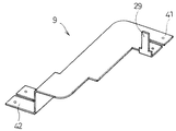
10個の二次電池2を端子側フレーム6、センターフレーム7、底側フレーム8で囲って互いに接合した後、図6に示すように、端子側フレーム6に形成された正極接続窓25と負極接続窓26から、図7に示す直列接続板9を隣り合う二次電池2にまたがって正極端子21と封口板23とに当接させ、正極接続部41を正極端子21に、負極接続部42を封口板23にそれぞれスポット溶接して10個の二次電池2を直列接続する。直列接続された正極側の接続端となる二次電池2の正極端子21には正極接続板10が、直列接続された負極側の接続端となる二次電池2の封口板23には負極接続板11がスポット溶接される。図7は直列接続板9の例を示すものであるが、直列接続板9、正極接続板10、負極接続板11には、それぞれ回路基板3に接続するための基板接続突起29が形成されている。
After ten
10個の二次電池2に直列接続板9、正極接続板10、負極接続板11がスポット溶接された端子側フレーム6の基板収容凹部28に回路基板3を収納すると、直列接続板9、正極接続板10及び負極接続板11に形成された基板接続突起29が回路基板3に形成された接続穴に挿入されるので、各基板接続突起29は回路基板3に半田付けされる。この接続構造により、10個の二次電池2それぞれを回路基板3に接続するためにリード配線することなく各二次電池2は回路基板3に接続され、回路基板3において基板接続突起29の間の電圧から各二次電池2個々の電池電圧を測定することができ、回路基板3に構成された電池保護回路は各二次電池2個々の電池電圧から二次電池2を過充電、過放電から保護する制御を実行し、充放電制御回路は電池電圧及び電池温度の測定に基づく充放電制御を実行する。
When the
基板収容凹部28に収容された回路基板3と、センターフレーム7上に配置されるコネクタケース12内に設けられる送風ファン4及び接続プラグ14との間にリード接続がなされた後、回路基板3は樹脂モールドされる。樹脂モールドは、リード線の接続部分を含む電子部品の実装面に溶融した樹脂を流し込んで固化させることにより、回路基板3の電気的絶縁性が強化されると同時に防湿・防水性を図ることができる。より好ましくは、基板収容凹部28内を埋めるように溶融した樹脂を流し込んで固化させると、回路基板3の全面が樹脂で包み込まれ、回路基板3と端子側フレーム6とが樹脂モールドが施される。この樹脂モールドにより回路基板3上に実装された電子部品の防湿対策が図られる他、パックケース5に形成された通気穴13a,13bなどから浸入した水により電気的障害が発生することを防止することができる。
After the lead connection is made between the
上記のように二次電池2及び回路基板3が一体に組み合わされた後、図2に示すように、4面に保護板16が配置され、センターフレーム7上に配した送風ファン4を囲ってコネクタケース12を配した後、右ケース5a及び左ケース5bからなるパックケース5を閉じて、図1に示したような電池パック1に完成される。
After the
この電池パック1は、図9に示すように、電動工具Aにスライド装着されると、コネクタケース12内に設けられた接続プラグ14が電動工具Aに設けられた接続ソケットに接続され、電動工具Aの始動スイッチのON操作により電動工具Aに駆動電力を供給する電力供給回路が閉じられる。電動工具Aの駆動負荷が大きくなると二次電池2からの放電量も増加するため温度上昇し、電池管理回路により所定温度が検出されると、電池管理回路は送風ファン4が駆動されるように制御するので、二次電池2は送風空気により冷却される。リチウムイオン二次電池における放電は発熱反応となるので、大電流放電により電動工具Aが使用されると二次電池2の温度上昇は激しく、電池管理回路は送風により二次電池2が60℃以下の温度状態で使用されるように送風ファン4を制御する。特に、真夏の炎天下のような高温環境では使用以前に二次電池2の温度が40℃を越える場合も想定でき、そのような環境下で電動工具Aが使用されると温度上昇も大きくなるので、電池管理回路は二次電池2の温度が高いときには電動工具Aの使用の如何にかかわらず送風ファン4を駆動して二次電池2を冷却し、二次電池2の温度が60℃を越えるような場合には電動工具Aに対する電力供給を停止して送風ファン4の駆動により二次電池2の温度が低下するように制御する。
As shown in FIG. 9, when the battery pack 1 is slid onto the electric tool A, the
送風ファン4は、その回転によりパックケース5内に外気を取り込む吸気ファンとして構成され、吸気した外気を二次電池2に吹き付けて冷却する。電池パック1を電動工具Aに装着すると、コネクタケース12は電動工具Aの電池パック装着面に当接するので、コネクタケース12の吸気口32に対向する電動工具Aの電池パック装着面には開口部が形成され、図9に示すように、電動工具Aの電池パック1の装着部位の側面には前記開口部に通じる外気取り入れ口aが形成される。
The blower fan 4 is configured as an intake fan that takes outside air into the
図8に白抜き矢印で示すように、送風ファン4はパックケース5内のセンターフレーム7上に配設されているので、送風ファン4が駆動されると、吸気口32から吸気された外気は所定間隔で並列配置された二次電池2の対向間を通過し、パックケース5の下に開口する下方通気穴13aから排出される空気流路が形成されるので、電動工具Aを駆動する大きな放電電流により温度上昇する二次電池2が冷却され、温度上昇が抑制される。また、センターフレーム7上に設けられた整流板15は、送風ファン4から送風されてきた空気の流れを両側に流して送風ファン4の直下にある二次電池2だけでなく端方向にある二次電池2にも送風空気を送ることができ、全ての二次電池2が均等に冷却されるように作用する。この整流板15に開口径及び開口位置を調整して開口部を形成することにより、整流板15の下に位置する二次電池2にも送風空気が当たるように調整することができ、各二次電池2に対する空冷状態を均等化して電池温度が平均化されるように調整することができる。
Since the blower fan 4 is disposed on the
電池パック1は、それが電動工具Aに装着されたとき、図9に示すように、電動工具Aの最下部と電池パック1の底面とが同一高さ位置となる寸法に形成することにより、電動工具Aを床面などに安定して立てることができる。図8に示すように、パックケース5の二次電池2の長手方向断面は、下方の両側に下方窪み31a及び上方の両側に上方窪み31bが形成され、この下方及び上方の各窪み31a,31bにそれぞれ下方通気穴13a、上方通気穴13bが形成されている。この下方及び上方の各窪み31a,31bが形成されていることにより、電動工具Aを立てた状態、即ち電動工具Aの駆動が停止されている状態でも下方通気穴13aは塞がれることはなく、破線矢印で示すように、下方通気穴13aから流入した外気が二次電池2の間を通って上方通気穴13bに抜ける空気の流れが形成される。特に、電動工具Aを駆動した後では二次電池2の温度が上昇しており、その熱によって上方通気穴13bに流れる上昇気流が発生し、それに伴って下方通気穴13aから外気が流入して二次電池2の間を通って上方通気穴13bに流れる空気の流れが形成され、温度上昇した二次電池2は送風ファン4が停止している状態でも冷却作用が促進され、速やかに二次電池2の温度を低下させることができる。
When the battery pack 1 is attached to the electric power tool A, as shown in FIG. 9, the lowermost part of the electric power tool A and the bottom surface of the battery pack 1 are formed to have the same height position. The electric tool A can be stood stably on the floor surface. As shown in FIG. 8, the longitudinal cross section of the
上記下方及び上方の各通気穴13a,13bは二次電池2の冷却に効果的に作用するが、雨中など水滴が飛散するような環境で電動工具Aが使用された場合や、水溜りのある床面に電動工具Aが置かれたような場合に、下方及び上方の各通気穴13a,13bから水が浸入する恐れがある。図8に示すように、パックケース5内に水が浸入しても、各二次電池2の封口板側は端子側フレーム6に囲われ、回路基板3は樹脂モールド30によって被覆されているので、通電部分に水が浸入することはなく、過酷な環境下での使用が想定される電動工具Aの電池パック1としての安全性が確保される。
The lower and
電動工具Aの駆動により電池容量が低下した場合には、電動工具Aから電池パック1を取り外し、図10に示すように、充電器Bに装着することにより二次電池2に対する充電がなされる。電池パック1は充電器Bに装着するときには、図示するように天地方向を逆にして充電器Bに装着され、充電器Bの電池パック1の装着位置に設けられた通風口から充電器B内の空気を吸気し、充電器Bの排熱と同時に充電中の二次電池2を冷却する。充電器Bの側にも排気ファンが設けられている場合には、送風ファン4と合わせた送風を実施すると、より効果的な冷却がなされる。
When the battery capacity is reduced by driving the electric power tool A, the battery pack 1 is removed from the electric power tool A, and the
使用直後の電動工具Aから取り外された電池パック1では、二次電池2の温度が充電に適した温度以上になっていることが予想でき、電池温度は電池管理回路で検出されると共にコネクタを通じて充電器B側でも検出されるので、電池温度が45℃以上である場合には充電は開始されず、電池温度が45℃以下になるように送風による冷却が継続された後に充電が開始されるように制御される。
In the battery pack 1 removed from the power tool A immediately after use, the temperature of the
以上説明した電池パック1では、二次電池2として扁平角形のものを適用しているが、円筒形に形成した二次電池を適用することも可能であり、本構成により同様の効果が得られる。
In the battery pack 1 described above, a flat rectangular battery is used as the
本発明に係る電池パックは、複数の二次電池は隣り合う間に間隙を設けて並列配置され、送風ファンからの送風空気を二次電池の配列間に流通させるので、機器や充電器に対して着脱可能とした小型の電池パックであっても冷却効果が向上し、大電流放電を可能とする電池パックをコンパクトに構成することが可能となり、電動工具などの電池電源として好適な電池パックを提供することができる。 In the battery pack according to the present invention, a plurality of secondary batteries are arranged in parallel with a gap between adjacent ones, and the blown air from the blower fan is circulated between the arrays of secondary batteries. Even with a small battery pack that can be attached and detached, the cooling effect is improved, and a battery pack that can discharge a large current can be configured in a compact manner. Can be provided.
1 電池パック
2 二次電池
3 回路基板
4 送風ファン
5 パックケース
6 端子側フレーム
7 センターフレーム
8 底側フレーム
12 コネクタケース
15 整流板
20 装着部
DESCRIPTION OF SYMBOLS 1
Claims (1)
前記複数の二次電池を所定間隔を隔てて並列保持し、前記装着部に二次電池の並列配置方向と交差する方向が送風方向となるように送風ファンが配設され、前記二次電池は、扁平角形に形成され、その最大面積平坦面が所定間隔を隔てて互いに対面するようにフレームによって保持され、さらに、送風空気の流れ方向を調整する整流板が設けられ、前記電池管理回路は、電池温度の検出に基づいて送風ファンの回転を制御し、排気ファンを持つ充電器と接続可能であり、前記排気ファンの排気空気の流れ方向上に、前記送風ファンが配置されることを特徴とする電池パック。 A plurality of secondary batteries in which the electrode plate group and the electrolyte solution are accommodated in the battery can, the opening end is sealed with a sealing plate, and the electrode terminal is provided on the sealing plate, and the operation state of each secondary battery is managed. A battery pack that includes a circuit board that constitutes a battery management circuit that is housed in a pack case and includes a mounting portion that is detachable from a device and a charger,
Wherein the plurality of secondary batteries in parallel maintained at a predetermined distance in a direction intersecting the parallel arrangement direction of the secondary battery to the mounting portion is blowing fan is arranged so that the air blowing direction, said secondary battery The flat plate is held by the frame so that the flat surfaces of the maximum area face each other at a predetermined interval, and a rectifying plate for adjusting the flow direction of the blown air is provided. The rotation of the blower fan is controlled based on the detection of the battery temperature, can be connected to a charger having an exhaust fan, and the blower fan is disposed on the flow direction of the exhaust air of the exhaust fan. Battery pack.
Priority Applications (1)
| Application Number | Priority Date | Filing Date | Title |
|---|---|---|---|
| JP2004011654A JP4635442B2 (en) | 2004-01-20 | 2004-01-20 | Battery pack |
Applications Claiming Priority (1)
| Application Number | Priority Date | Filing Date | Title |
|---|---|---|---|
| JP2004011654A JP4635442B2 (en) | 2004-01-20 | 2004-01-20 | Battery pack |
Publications (2)
| Publication Number | Publication Date |
|---|---|
| JP2005209367A JP2005209367A (en) | 2005-08-04 |
| JP4635442B2 true JP4635442B2 (en) | 2011-02-23 |
Family
ID=34898282
Family Applications (1)
| Application Number | Title | Priority Date | Filing Date |
|---|---|---|---|
| JP2004011654A Expired - Fee Related JP4635442B2 (en) | 2004-01-20 | 2004-01-20 | Battery pack |
Country Status (1)
| Country | Link |
|---|---|
| JP (1) | JP4635442B2 (en) |
Families Citing this family (16)
| Publication number | Priority date | Publication date | Assignee | Title |
|---|---|---|---|---|
| GB2431128B (en) * | 2005-10-11 | 2009-11-18 | Bosch Gmbh Robert | Electric tool |
| US10014508B2 (en) * | 2006-11-27 | 2018-07-03 | Lg Chem, Ltd. | Battery module assembly |
| KR100920207B1 (en) * | 2006-11-27 | 2009-10-06 | 주식회사 엘지화학 | Power switching module for manufacturing battery module assembly |
| GB0723914D0 (en) * | 2007-12-07 | 2008-01-23 | Johnson Electric Sa | A power tool |
| JP5433427B2 (en) * | 2010-01-04 | 2014-03-05 | 三菱重工業株式会社 | Battery pack |
| KR101281811B1 (en) * | 2010-08-16 | 2013-07-15 | 주식회사 엘지화학 | Battery Pack Having Improved Structure Stability |
| JP5244931B2 (en) * | 2011-02-22 | 2013-07-24 | 日立ビークルエナジー株式会社 | Power storage module |
| JP6065339B2 (en) * | 2012-08-13 | 2017-01-25 | 日立工機株式会社 | Back load type power supply |
| KR102177265B1 (en) * | 2014-03-03 | 2020-11-10 | 두산인프라코어 주식회사 | Energy storing device and hybrid construction machine using the same |
| US20150263397A1 (en) * | 2014-03-13 | 2015-09-17 | Ford Global Technologies, Llc | Side mounted traction battery thermal plate |
| KR102349918B1 (en) | 2018-11-21 | 2022-01-10 | 주식회사 엘지에너지솔루션 | Battery module |
| WO2022188910A1 (en) | 2021-03-11 | 2022-09-15 | Bachmann Gmbh | Mobile energy storage unit; method for shielding at least one electronics module and/or at least one battery module of a mobile energy storage unit |
| EP4305729A1 (en) | 2021-03-11 | 2024-01-17 | Bachmann GmbH | Mobile energy storage unit |
| DE102021105923B4 (en) | 2021-03-11 | 2025-03-20 | Bachmann Gmbh | Mobile energy storage unit, method for shielding at least one electronic and/or at least one battery module of a mobile energy storage unit |
| JP7724630B2 (en) | 2021-04-01 | 2025-08-18 | 株式会社マキタ | Battery packs for power tools |
| CN116315285B (en) * | 2023-05-06 | 2023-11-21 | 江苏智泰新能源科技有限公司 | Active separation type power supply connection assembly of battery pack |
Family Cites Families (5)
| Publication number | Priority date | Publication date | Assignee | Title |
|---|---|---|---|---|
| JP2931361B2 (en) * | 1990-04-06 | 1999-08-09 | 三洋電機株式会社 | Heat dissipation device for storage battery system |
| US6455186B1 (en) * | 1998-03-05 | 2002-09-24 | Black & Decker Inc. | Battery cooling system |
| JP3829477B2 (en) * | 1998-06-19 | 2006-10-04 | 日立工機株式会社 | Battery pack cooling device |
| JP4566392B2 (en) * | 2000-11-16 | 2010-10-20 | レノボ シンガポール プライヴェート リミテッド | Battery, battery pack, computer apparatus, electric device, and battery temperature control method for determining action level associated with temperature control |
| JP2003174720A (en) * | 2001-09-28 | 2003-06-20 | Mitsumi Electric Co Ltd | Protection circuit for secondary battery and protection circuit IC |
-
2004
- 2004-01-20 JP JP2004011654A patent/JP4635442B2/en not_active Expired - Fee Related
Also Published As
| Publication number | Publication date |
|---|---|
| JP2005209367A (en) | 2005-08-04 |
Similar Documents
| Publication | Publication Date | Title |
|---|---|---|
| JP4662530B2 (en) | Battery pack | |
| US7846577B2 (en) | Battery pack | |
| JP4635442B2 (en) | Battery pack | |
| JP5209036B2 (en) | Battery assembly, electric vehicle, and battery housing | |
| EP3136497B1 (en) | Battery module including water cooling structure | |
| CN102197531B (en) | Battery module and battery pack using the same | |
| JP3569152B2 (en) | battery pack | |
| KR101726383B1 (en) | Apparatus for testing battery's performance | |
| KR101252944B1 (en) | Battery pack with enhanced radiating ability | |
| KR101252963B1 (en) | Battery pack with improved heat dissipation | |
| CN109845024B (en) | Battery system and electric vehicle including the same | |
| US9614197B2 (en) | Onboard battery | |
| KR20190001410A (en) | Battery Module | |
| JP2015172997A (en) | Battery system, and vehicle and power storage device comprising battery system | |
| JP2013219043A (en) | Power supply device | |
| KR102877728B1 (en) | Battery module and battery pack having the same | |
| JP2005209369A (en) | Battery pack | |
| KR102026386B1 (en) | Battery module | |
| JP4593930B2 (en) | Battery pack | |
| WO2014010437A1 (en) | Power source device and vehicle provided with said power source device | |
| JP4752180B2 (en) | Battery pack | |
| KR100850849B1 (en) | Battery case for thermal control and battery pack structure using the same | |
| KR100684758B1 (en) | Secondary battery module | |
| JP2020198177A (en) | Battery module | |
| JP7711300B2 (en) | Battery module, battery pack including same, and automobile |
Legal Events
| Date | Code | Title | Description |
|---|---|---|---|
| A621 | Written request for application examination |
Free format text: JAPANESE INTERMEDIATE CODE: A621 Effective date: 20061207 |
|
| RD02 | Notification of acceptance of power of attorney |
Free format text: JAPANESE INTERMEDIATE CODE: A7422 Effective date: 20090526 |
|
| RD04 | Notification of resignation of power of attorney |
Free format text: JAPANESE INTERMEDIATE CODE: A7424 Effective date: 20091026 |
|
| RD03 | Notification of appointment of power of attorney |
Free format text: JAPANESE INTERMEDIATE CODE: A7423 Effective date: 20091228 |
|
| RD05 | Notification of revocation of power of attorney |
Free format text: JAPANESE INTERMEDIATE CODE: A7425 Effective date: 20100120 |
|
| A977 | Report on retrieval |
Free format text: JAPANESE INTERMEDIATE CODE: A971007 Effective date: 20100601 |
|
| A131 | Notification of reasons for refusal |
Free format text: JAPANESE INTERMEDIATE CODE: A131 Effective date: 20100615 |
|
| A521 | Request for written amendment filed |
Free format text: JAPANESE INTERMEDIATE CODE: A523 Effective date: 20100805 |
|
| TRDD | Decision of grant or rejection written | ||
| A01 | Written decision to grant a patent or to grant a registration (utility model) |
Free format text: JAPANESE INTERMEDIATE CODE: A01 Effective date: 20101026 |
|
| A01 | Written decision to grant a patent or to grant a registration (utility model) |
Free format text: JAPANESE INTERMEDIATE CODE: A01 |
|
| A61 | First payment of annual fees (during grant procedure) |
Free format text: JAPANESE INTERMEDIATE CODE: A61 Effective date: 20101108 |
|
| FPAY | Renewal fee payment (event date is renewal date of database) |
Free format text: PAYMENT UNTIL: 20131203 Year of fee payment: 3 |
|
| FPAY | Renewal fee payment (event date is renewal date of database) |
Free format text: PAYMENT UNTIL: 20131203 Year of fee payment: 3 |
|
| LAPS | Cancellation because of no payment of annual fees |