JP4635385B2 - IC card reader, IC card reader body and card holder - Google Patents
IC card reader, IC card reader body and card holder Download PDFInfo
- Publication number
- JP4635385B2 JP4635385B2 JP2001212143A JP2001212143A JP4635385B2 JP 4635385 B2 JP4635385 B2 JP 4635385B2 JP 2001212143 A JP2001212143 A JP 2001212143A JP 2001212143 A JP2001212143 A JP 2001212143A JP 4635385 B2 JP4635385 B2 JP 4635385B2
- Authority
- JP
- Japan
- Prior art keywords
- card
- data reading
- card holder
- holder
- card reader
- Prior art date
- Legal status (The legal status is an assumption and is not a legal conclusion. Google has not performed a legal analysis and makes no representation as to the accuracy of the status listed.)
- Expired - Fee Related
Links
Images





Landscapes
- Credit Cards Or The Like (AREA)
Description
【0001】
【発明の属する技術分野】
本発明は、非接触式ICカードとの間で電波信号を用いて通信を行うことによりICカードに記憶されているデータを読取るICカードリーダ、そのICカードリーダを構成する本体並びにカードホルダに関する。
【0002】
【従来の技術】
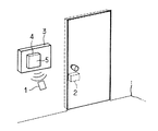
非接触式ICカードは、ICカードリーダとの間で電波信号を用いて通信を行うためユーザにとって利便性が良好であり、使用形態についても様々なものが想定される。例えば、図11に示すように、入室時にICカード1に記憶されているユーザのIDコードを読取ることで入室者をチェックして電気錠2の解錠を行うようなシステムでは、コントローラ3に組み込まれているICカードリーダ4はIDコードを一瞬読取るだけである。従って、通信に要する時間は極めて短かく、ユーザはICカードリーダ4の読取り部5の近傍にICカード1をかざすだけで良い(オープンタイプと称する)。
【0003】
また、例えば、図12に示すように、上記システムのセキュリティレベルをより高めた方式では、ICカードリーダ4の読取り部5にはICカード1を保持するためのカードホルダ6を備え、コントローラ3には暗証番号入力用のキーパッド7を備えている。そして、ユーザは、入室時にはカードホルダ6にICカード1を挿入して保持させ、ICカードリーダ4がIDコードを連続的に読み出している間にキーパッド7を操作して暗証番号を入力するタイプのものがある(ホールドタイプと称する)。
【0004】
【発明が解決しようとする課題】
前者のオープンタイプでは、ICカードリーダ4側の送信電力を大きく設定すれば、ICカードリーダ4とICカード1との間の通信可能エリアが広くなるのでユーザにとっては利便性が向上する。しかしながら、送信電力を所定値以上に大きく設定する場合は、無線局としての免許申請が必要となる。
一方、後者のホールドタイプでは、ICカード1はカードホルダ6に挿入保持された状態でICカードリーダ4と通信するため、送信電力をそれ程大きく設定する必要はない。
【0005】
このようにタイプの異なるシステムに対応するためには、ICカードリーダ4の構成についてカードホルダ6があるものとないものとを作り分けたり、送信電力設定が異なるものを調整し分けたりする必要がある。しかしながら、カードホルダを有する別タイプのICカードリーダを用意することになると製品や販売管理等が煩雑となるおそれがある。
【0006】
本発明は上記事情に鑑みてなされたものであり、その目的は、より広範な使用形態に対応することができるICカードリーダ、そのICカードリーダを構成する本体並びにカードホルダを提供することにある。
【0007】
【課題を解決するための手段】
請求項1記載のICカードリーダによれば、内部に通信用アンテナが配置されており、ICカードが近接した状態でデータの読取りが行われる本体のデータ読取り部に対して、ICカードを保持するためのカードホルダが装着可能に構成されている。即ち、一回の利用に付きICカードとの通信が一瞬しか行われないアプリケーションにおいては、本体のデータ読取り部にカードホルダを装着せずに使用すれば良く、逆に、一回の利用に付きICカードとの通信が比較的長い時間にわたって複数回行われる場合があるアプリケーションでは、データ読取り部にカードホルダを装着させて使用すれば良い。
【0008】
そして、後者の場合、ICカードはICカードリーダに対して常に近接した状態にあるので、通信可能距離は前者の場合より短くなっても構わない。そこで、カードホルダの少なくとも一部を導電性材料からなるシールド部で構成することで、データ読取り部内に配置されている通信用アンテナより送信される電波信号のレベルを抑制することができ、無線局の免許申請を行わずとも使用することが可能となる。従って、ICカードリーダの本体を用途に応じて作り分ける必要がなくなり、より広範な使用形態に対応することができる。
そして、カードホルダをデータ読取り部に装着する方向が複数選択可能に構成されるので、ICカードリーダ本体を動かさずともユーザとICカードリーダ本体との配置関係、或いはICカードリーダ本体とその他の装置との配置関係等に対してカードの着脱方向が適当となるように変化させることができる。
更に、カードホルダをデータ読取り部に装着する方向と、装着されたカードホルダに保持されているICカードを取り出す方向とが異なるように構成する。即ち、カードホルダがデータ読取り部に対して着脱可能に構成されている場合に、カードホルダを装着する方向とホルダに保持されているICカードを取り出す方向とが一致すると、ICカードの荷重が作用してカードホルダが脱落するおそれがある。従って、2つの方向が異なるように構成すればカードホルダの脱落を防止することができる。
【0009】
請求項2記載のICカードリーダによれば、シールド部を、通信用アンテナがなすループ径よりも大なる径を有するループ状に構成する。斯様に構成した場合は、必ずしもカードホルダ全体をシールド部としない場合であっても、通信用アンテナより送信される電波信号のレベルを効果的に抑制することができる。
【0010】
請求項3記載のICカードリーダによれば、カードホルダは、シールド部とデータ読取り部との間にICカードを挿入保持するように構成される。斯様に構成すれば、ICカードがICカードリーダに送信する電波信号のレベルをシールド部が抑制することなしに、データ読取り部からの過剰な電波輻射を抑えることができる。
【0013】
請求項4記載のICカードリーダによれば、カードホルダの表面にICカードの挿入方向を表示することで、ユーザが挿入方向を直観的に把握し易くすることができる。
【0014】
請求項5記載のICカードリーダによれば、カードホルダのシールド部を、データ読取り部に対して装着された場合、本体側のフレームグランドに電気的に接続されるように構成するので、シールド部をグランド電位に設定して不要輻射のシールド効果を高めることができる。
【0015】
請求項6記載のICカードリーダによれば、本体側の一部にも、データ読取り部の通信用アンテナより送信される電波信号の不要輻射を抑制するように、少なくとも一部が導電性材料で構成されたシールド部を備える。即ち、通信用アンテナからICカード以外の方向に送信される電波信号は通信に寄与することなく確実に不要輻射となるので、上記のようにシールド部を備えることで本体側においても不要輻射を抑制してトータルでの輻射レベルを低下させることができる。
【0016】
【発明の実施の形態】
(第1実施例)
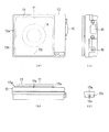
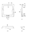
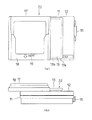
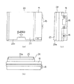
以下、本発明の第1実施例について図1乃至図5を参照して説明する。図2(a)〜(c)はリーダライタ本体の三面図,図3(a)〜(c)はカードホルダの三面図,図1(a)〜(c)はリーダライタ本体にカードホルダを装着した状態のリーダライタの三面図を示す。
【0017】
リーダライタ本体(ICカードリーダ本体)11は、略矩形箱状の筐体12の正面側にデータ読取り部13を備えている。データ読取り部13は外形が正方形状であり、全体が筐体12から若干突出するようにして形成されている。また、その外形の周縁部13aは、筐体12の正面に接合している部分(接合部13b)に対して僅かに外方に張り出した形状になっている。そして、データ読取り部13の内部には、ICカードと電波信号により通信を行うためのアンテナコイル14(破線で示す,通信用アンテナ)が配置されている。
【0018】
図2(c)に示すように、リーダライタ本体11の右側面側には、例えばDsub9ピンのRS−232C用コネクタ15と、図示しないACアダプタのプラグによって動作用の直流電源が供給されるDCINジャック16とが配置されている。コネクタ15には、リーダライタの上位装置であるパソコン等とシリアル通信を行うためのケーブルが接続される。
【0019】
カードホルダ17は略正方形状の枠体(シールド部)17aと、その枠体17a正面側の下半分に、ICカードを保持するために略U字状に形成されている保持部18とで構成されている。図3(c)に示すように、保持部18の上方側は、ユーザがICカードを挿入する場合に角度を与えるため枠体17aに対して若干手前側(正面側)に傾斜をなすように形成されている。尚、枠体17aは例えば金属(例えば、アルミニウムやステンレス)などの導電性材料で構成されている。
【0020】
また、保持部18の下辺側には、ICカードの挿入方向を示す下向き矢印と“card”の文字からなる表示19が印刷または掘り込みなどで表されている。
枠体17aの上辺部と下辺部とは背面側に折り返した形状をなすように端部17u,17dが延設されており(図3(c)参照)、ガイド部20u,20dを夫々構成している。
【0021】
そして、図4に示すように、カードホルダ17は、本体11のデータ読取り部13に対して側方から取り付けられる。即ち、ガイド部20u,20dを、周縁部13aと接合部13bとで形成されている段差に合わせて左側方から嵌め込み、右方向にスライドさせるようにして嵌合させる。
【0022】
ここで、図3(a),(d)に示すように、ガイド部20u,20d側には、その先端面における中央位置に、本体11と嵌合させるための突起部21u,21dが設けられている。一方、接合部13bの四辺夫々の中央位置には、突起部21u,21dを受け入れるための窪み部13cが形成されており、カードホルダ17が図4に示すように嵌合された場合は、データ読取り部13の上辺部と下辺部とに設けられている窪み部13cがカードホルダ17の突起部21u,21dを受け入れるようになっている。
【0023】
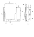
以上のカード本体11とホルダ17とでリーダライタ(ICカードリーダ)22が構成されている。そして、図1に示すように本体11にホルダ17が装着された場合には、図5に示すように、ホルダ17の保持部18に非接触式のICカード23を挿入してセットすることが可能となる。この場合、ホルダ17を本体11に装着させる方向と、ICカード23をホルダ17に挿入したり取り出したりする方向とは90度異なっている。そして、ICカード23がホルダ17に完全にセットされた状態では、ICカード23は略垂直に保持されるようになっている。
【0024】
また、データ読取り部13の形状から明らかなように、本体11に対するホルダ17の取り付けは、図4に示す方向に対して90度,180度若しくは270度異なる方向であっても可能となっている。
【0025】
次に、本実施例の作用について説明する。上述した図11に示す場合のようにオープンタイプとして用いるアプリケーションでは、カードホルダ17をデータ読取り部13に装着することなく使用する。従って、この場合は従来と全く同様の使用形態となり、実際に使用するに当たっては無線局の免許申請を行うようにする。
【0026】
一方、図12に示す場合のようにホールドタイプとして用いるアプリケーションでは、カードホルダ17をデータ読取り部13に装着した状態で使用する。すると、導電性材料で構成されているカードホルダ17の枠体17aがアンテナコイル14より送信される電波信号の一部をシールドするように作用するため、その輻射レベルはオープンタイプの場合よりも低下し、実際の使用に当たって無線局の免許申請を行う必要はなくなるように本体11側の送信電力設定とカードホルダ17によるシールド効果との関係が設定されている。
【0027】
以上のように本実施例によれば、リーダライタ本体11のデータ読取り部13に対して、ICカード23を保持するためのカードホルダ17を装着可能に構成したので、一回の利用に付きICカード23との通信が一瞬しか行われないオープンタイプのアプリケーションにおいては、ユーザは本体11のデータ読取り部13にカードホルダ17を装着せずに使用すれば良く、逆に、一回の利用に付きICカード23との通信が比較的長い時間にわたって複数回行われる場合があるホールドタイプのアプリケーションでは、データ読取り部13にカードホルダ17を装着させて使用すれば良い。
【0028】
そして、後者の場合、ICカード23はリーダライタ本体11に対して常に近接した状態にあり通信可能距離は前者の場合より短くなっても構わないので、カードホルダ17の枠体17aを導電性材料を用いて構成することで、データ読取り部13内のアンテナコイル14より送信される電波信号のレベルを抑制して無線局の免許申請を行わずとも使用することが可能となる。従って、リーダライタ本体11を用途に応じて作り分ける必要がなくなり、より広範な使用形態に対応することができる。
【0029】
また、データ読取り部13の外形を正方形状に形成して、カードホルダ17を装着する方向を複数選択可能にしたので、リーダライタ本体11を動かさずともユーザと本体11との配置関係、或いは本体11とパソコン等との配置関係等に対してICカード23の着脱方向が適当となるように変化させることができる。
更に、ホルダ17をデータ読取り部13に装着する方向と、装着されたホルダ17に保持されているICカード23を取り出す方向とを直交させるようにしたので、ICカード23を挿入した場合にホルダ17の脱落を防止することができる。加えて、カードホルダ17の表面にICカード23の挿入方向を表示する表示19を配置したので、ユーザが挿入方向を直観的に把握し易くすることができる。
【0030】
(第2実施例)
図6及び図7は本発明の第2実施例を示すものであり、第1実施例と同一部分には同一符号を付して説明を省略し、以下異なる部分についてのみ説明する。第2実施例のカードホルダ24はポケット状に形成される保持部(シールド部)25を備え、導電性材料で構成されている。そして、保持部25に対するICカード23の挿入方向と、カードホルダ24をデータ読取り部13に装着する方向とが同一となるように構成されている。
【0031】
即ち、図7に示すように、カードホルダ24の取付け部26は、保持部25の背面側において、その上端の開放側が保持部25のカード挿入口25aと180度逆となるようにコ字状に形成されている。取付け部26のコ字をなしている部分は、データ読取り部13の周縁部13aに嵌合するように断面がやはりコ字状となるガイド部26aとなっている。そして、カードホルダ24を、取付け部26の開放側からリーダライタ本体11のデータ読取り部13に装着する。
【0032】
以上のように構成された第2実施例によれば、カードホルダ24のシールド部たる保持部25をポケット状に形成したので、シールド効果をより向上させて不要輻射レベルを低減することができる。そして、カードホルダ24は、保持部25とデータ読取り部13との間にICカード23を挿入保持させる構成なので、、ICカード23がリーダライタ本体11側に送信する電波信号のレベルを保持部25が抑制することなく、データ読取り部13側からの不要輻射を抑えることができる。
【0033】
(第3実施例)
図8及び図9は本発明の第3実施例を示すものであり、第1実施例と同一部分には同一符号を付して説明を省略し、以下異なる部分についてのみ説明する。第3実施例では、リーダライタ本体27におけるデータ読取り部28の構造がデータ読取り部13とは異なっている。即ち、データ読取り部28は、図8(b)に示すように、金属などの導電性材料によって正面側が開口した矩形箱状に形成されるシールド部29と、そのシールド部29の正面側を覆うように配置される樹脂製の取付け板30とで構成されている。尚、シールド部29は、本体27のフレームグランドとなっている。
【0034】
データ読取り部28の内部にはアンテナコイル14が配置されており、データ読取り部28は、正面側からシールド部29を本体27の内部に埋め込むようにして取付けられている。データ読取り部28の内部では、アンテナコイル14に対してファラデーシールド31が施されている。ファラデーシールド31は、取付け板30の内部側において、アンテナコイル14のコイルループをカバーするように、例えば銅箔を、一部を切り欠いた円環(所謂ランドルト環)状に配置したものである。ファラデーシールド31を施すことで、アンテナコイル14より放射される近傍の電界成分の一部を抑えて放射特性を調整している。
【0035】
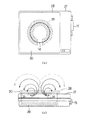
図9は、データ読取り部28にカードホルダを装着した状態におけるシールド部32S部分のみを示す(尚、一部についは透視した断面を示している)。シールド部32Sは、カードホルダ17の枠体17aに対応する部分の一部が導電性材料で構成されており、図9(a)に示すように、正面から見ると、アンテナコイル14のループの外部側でその一部がファラデーシールド31の外縁にかかるように形成されている。
【0036】
以上のように構成された第3実施例によれば、ファラデーシールド31によって放射特性が調整されたアンテナコイル14の電波放射を、カードホルダのシールド部32Sによって効果的に抑制することができる。また、本体27側にもシールド部29を備えることによって、本体27側における正面方向以外の不要輻射を抑制することができる。
【0037】
(第4実施例)
図10は本発明の第4実施例であり、第3実施例と異なる部分についてのみ説明する。第4実施例では、データ読取り部28を備えたリーダライタ本体27に対してカードホルダ33を装着する構成であるが、そのカードホルダ33は、第2実施例のカードホルダ24と略同様に全体が導電性材料で構成されており、保持部(シールド部)34はポケット状に形成されている。そして、カードホルダ33をデータ読取り部28に装着すると、カードホルダ33とシールド部29 (フレームグランド)とは電気的に接続されるようになっている。
【0038】
以上のように構成された第4実施例によれば、カードホルダ33をデータ読取り部28に装着した場合、本体側27のシールド部29と電気的に接続されるようにしたので、カードホルダ33をグランド電位に設定して不要輻射のシールド効果を高めることができる。
【0039】
本発明は上記し且つ図面に記載した実施例にのみ限定されるものではなく、次のような変形または拡張が可能である。
カードホルダの表面に、ICカードの挿入方向を表示することは、必要に応じて行えば良い。
ICカードに記憶されているデータを読み込む機能だけを有しているICカードリーダに適用しても良い。
カードホルダは、例えば樹脂中に金属フィラー等の導電性材料を混入して形成しても良い。また、枠体のデータ読取り部に対向する側に導電ペースト(導電性材料)を塗布して構成としても良い。
【図面の簡単な説明】
【図1】本発明の第1実施例であり、(a)〜(c)はリーダライタ本体にカードホルダを装着した状態のリーダライタの三面図
【図2】(a)〜(c)はリーダライタ本体の三面図、(d)は(b)の一部を拡大して示す図
【図3】(a)〜(c)はカードホルダの三面図、(d)は(c)の一部を拡大して示す図
【図4】(a)はカードホルダをリーダライタ本体に装着する途中の状態を示す正面図、(b)は同底面図
【図5】(a)はカードホルダが装着された状態のリーダライタにICカードを挿入した状態を示す正面図、(b)は同側面図
【図6】本発明の第2実施例を示す図1相当図
【図7】カードホルダを背面側から見た斜視図
【図8】本発明の第3実施例であり、(a)は一部を透視して示すリーダライタ本体の正面図、(b)はリーダライタ本体の上面図(一部については透視した断面を示す)
【図9】カードホルダを装着した場合のシールド部のみを示す図8相当図
【図10】本発明の第4実施例であり、カードホルダを装着した場合のリーダライタの上面図(一部については透視した断面を示す)
【図11】従来技術のリーダライタにおけるオープンタイプの使用例を示す図
【図12】同ホールドタイプの使用例を示す図
【符号の説明】
11はリーダライタ本体、13はデータ読取り部、14はアンテナコイル(通信用アンテナ)、17はカードホルダ、17aは枠体(シールド部)、19は表示、22はリーダライタ(ICカードリーダ)、23はICカード、24はカードホルダ、25は保持部(シールド部)、27はリーダライタ本体、28はデータ読取り部、29はシールド部、32はカードホルダ、32Sはシールド部、33はカードホルダ、34は保持部(シールド部)を示す。[0001]
BACKGROUND OF THE INVENTION
The present invention relates to an IC card reader that reads data stored in an IC card by communicating with a non-contact type IC card using a radio wave signal, a main body constituting the IC card reader, and a card holder.
[0002]
[Prior art]
The non-contact type IC card is convenient for the user because it communicates with the IC card reader using a radio wave signal, and various forms of use are assumed. For example, as shown in FIG. 11, in a system in which a user is checked by reading a user ID code stored in the IC card 1 when entering the room and the electric lock 2 is unlocked, the
[0003]
Further, for example, as shown in FIG. 12, in the system in which the security level of the system is further increased, the
[0004]
[Problems to be solved by the invention]
In the former open type, if the transmission power on the
On the other hand, in the latter hold type, since the IC card 1 communicates with the
[0005]
In order to cope with such different types of systems, it is necessary to make a difference between the configuration of the
[0006]
The present invention has been made in view of the above circumstances, and an object of the present invention is to provide an IC card reader capable of dealing with a wider range of usage forms, a main body constituting the IC card reader, and a card holder. .
[0007]
[Means for Solving the Problems]
According to the IC card reader of the first aspect, the communication antenna is disposed inside, and the IC card is held with respect to the data reading unit of the main body that reads data in a state where the IC card is close to the IC card reader. Therefore, the card holder is configured to be mountable. In other words, in applications where communication with an IC card is performed only once for a single use, it can be used without attaching a card holder to the data reader of the main unit. In an application in which communication with the IC card may be performed a plurality of times over a relatively long time, the card reader may be attached to the data reading unit.
[0008]
In the latter case, since the IC card is always close to the IC card reader, the communicable distance may be shorter than in the former case. Therefore, by configuring at least a part of the card holder with a shield part made of a conductive material, the level of the radio signal transmitted from the communication antenna arranged in the data reading part can be suppressed, and the radio station It can be used without applying for a license. Therefore, it is not necessary to make the main body of the IC card reader according to the use, and it is possible to deal with a wider range of usage.
Further, since a plurality of directions in which the card holder is mounted on the data reading unit can be selected, the arrangement relationship between the user and the IC card reader main body or the IC card reader main body and other devices can be selected without moving the IC card reader main body. Can be changed so that the card mounting / removal direction is appropriate.
Further, the direction in which the card holder is attached to the data reading unit is different from the direction in which the IC card held by the attached card holder is taken out. That is, when the card holder is configured to be detachable from the data reading unit, if the direction in which the card holder is attached coincides with the direction in which the IC card held by the holder is taken out, the load on the IC card acts. The card holder may fall off. Therefore, if the two directions are different, the card holder can be prevented from falling off.
[0009]
According to the IC card reader of the second aspect, the shield part is configured in a loop shape having a diameter larger than the loop diameter formed by the communication antenna. When configured in this manner, the level of the radio signal transmitted from the communication antenna can be effectively suppressed even if the entire card holder is not necessarily the shield portion.
[0010]
According to the IC card reader of the third aspect, the card holder is configured to insert and hold the IC card between the shield part and the data reading part. If comprised in this way, the excessive radio wave radiation from a data reading part can be suppressed, without a shield part suppressing the level of the radio signal which an IC card transmits to an IC card reader.
[0013]
According to the IC card reader of the fourth aspect, by displaying the insertion direction of the IC card on the surface of the card holder, the user can easily grasp the insertion direction intuitively.
[0014]
According to the IC card reader of
[0015]
According to the IC card reader of
[0016]
DETAILED DESCRIPTION OF THE INVENTION
(First embodiment)
Hereinafter, a first embodiment of the present invention will be described with reference to FIGS. 2 (a) to (c) are three views of the reader / writer body, FIGS. 3 (a) to 3 (c) are three views of the card holder, and FIGS. 1 (a) to 1 (c) show the card holder in the reader / writer body. The three views of the reader / writer in the mounted state are shown.
[0017]
The reader / writer main body (IC card reader main body) 11 includes a
[0018]
As shown in FIG. 2C, on the right side surface of the reader / writer
[0019]
The
[0020]
In addition, on the lower side of the holding
[0021]
As shown in FIG. 4, the
[0022]
Here, as shown in FIGS. 3A and 3D, on the
[0023]
The
[0024]
Further, as apparent from the shape of the
[0025]
Next, the operation of this embodiment will be described. In the application used as an open type as shown in FIG. 11 described above, the
[0026]
On the other hand, in an application used as a hold type as shown in FIG. 12, the
[0027]
As described above, according to the present embodiment, since the
[0028]
In the latter case, the
[0029]
Further, since the outer shape of the
Furthermore, since the direction in which the
[0030]
(Second embodiment)
6 and 7 show a second embodiment of the present invention. The same parts as those in the first embodiment are denoted by the same reference numerals and the description thereof is omitted. Only the different parts will be described below. The
[0031]
That is, as shown in FIG. 7, the mounting
[0032]
According to the second embodiment configured as described above, since the holding
[0033]
(Third embodiment)
8 and 9 show a third embodiment of the present invention. The same parts as those in the first embodiment are denoted by the same reference numerals and the description thereof is omitted, and only different parts will be described below. In the third embodiment, the structure of the
[0034]
The
[0035]
FIG. 9 shows only the
[0036]
According to the third embodiment configured as described above, radio wave radiation of the
[0037]
(Fourth embodiment)
FIG. 10 shows a fourth embodiment of the present invention, and only parts different from the third embodiment will be described. In the fourth embodiment, the
[0038]
According to the fourth embodiment configured as described above, when the
[0039]
The present invention is not limited to the embodiments described above and illustrated in the drawings, and the following modifications or expansions are possible.
Displaying the insertion direction of the IC card on the surface of the card holder may be performed as necessary.
You may apply to the IC card reader which has only the function to read the data memorize | stored in the IC card.
The card holder may be formed by mixing a conductive material such as a metal filler in a resin, for example. Alternatively, a conductive paste (conductive material) may be applied to the side of the frame that faces the data reading unit.
[Brief description of the drawings]
FIG. 1 is a first embodiment of the present invention, and (a) to (c) are three views of a reader / writer with a card holder attached to the reader / writer body. FIG. 2 (a) to (c) FIG. 3D is an enlarged view of a part of FIG. 3B. FIG. 3A to FIG. 3C are three side views of the card holder, and FIG. FIG. 4A is a front view showing a state in the middle of mounting the card holder to the reader / writer main body, FIG. 5B is a bottom view thereof, and FIG. 5A is a view of the card holder. FIG. 6B is a side view showing the state in which the IC card is inserted into the attached reader / writer. FIG. 6 is a side view of the second embodiment of the present invention. FIG. FIG. 8 is a perspective view as seen from the back side. FIG. 8 is a third embodiment of the present invention, and FIG. ) Top view of a reader-writer main body (a portion showing a cross section perspective for)
FIG. 9 is a view corresponding to FIG. 8 showing only the shield portion when the card holder is mounted. FIG. 10 is a top view of the reader / writer when the card holder is mounted according to the fourth embodiment of the present invention (partially Indicates a cross-sectional view)
FIG. 11 is a diagram showing an example of use of an open type in a conventional reader / writer. FIG. 12 is a diagram of an example of use of the hold type.
11 is a reader / writer body, 13 is a data reader, 14 is an antenna coil (communication antenna), 17 is a card holder, 17a is a frame (shield), 19 is a display, 22 is a reader / writer (IC card reader), 23 is an IC card, 24 is a card holder, 25 is a holding part (shield part), 27 is a reader / writer body, 28 is a data reading part, 29 is a shield part, 32 is a card holder, 32S is a shield part, and 33 is a card holder. , 34 indicates a holding part (shield part).
Claims (8)
内部に通信用アンテナが配置されており前記ICカードが近接した状態でデータの読取りが行われる本体のデータ読取り部に対して、ICカードを保持するためのカードホルダが装着可能に構成されており、
前記カードホルダは、前記データ読取り部に装着された場合に、その内部に配置されている通信用アンテナより送信される電波信号のレベルを抑制するように、少なくとも一部が導電性材料からなるシールド部で構成され、
前記カードホルダを前記データ読取り部に装着する方向が複数選択可能に構成され、更に、前記カードホルダを前記データ読取り部に装着する方向と、装着されたカードホルダに保持されているICカードを取り出す方向とが異なるように構成されていることを特徴とするICカードリーダ。In an IC card reader that reads data stored in an IC card by communicating with a non-contact IC card using radio signals,
A communication antenna is arranged inside, and a card holder for holding the IC card can be attached to the data reading unit of the main body where the data is read in the state where the IC card is in proximity. ,
The card holder is a shield made of a conductive material at least partially so as to suppress a level of a radio wave signal transmitted from a communication antenna disposed therein when the card holder is attached to the data reading unit. is composed of parts,
A plurality of directions for attaching the card holder to the data reading unit can be selected, and further, a direction for attaching the card holder to the data reading unit and an IC card held by the attached card holder are taken out. An IC card reader characterized in that the direction is different .
前記シールド部は、前記通信用アンテナのループ径よりも大なる径を有するループ状に構成されていることを特徴とする請求項1記載のICカードリーダ。The communication antenna arranged inside the data reading unit is configured in a loop shape,
2. The IC card reader according to claim 1, wherein the shield part is configured in a loop shape having a diameter larger than a loop diameter of the communication antenna.
Priority Applications (1)
| Application Number | Priority Date | Filing Date | Title |
|---|---|---|---|
| JP2001212143A JP4635385B2 (en) | 2001-07-12 | 2001-07-12 | IC card reader, IC card reader body and card holder |
Applications Claiming Priority (1)
| Application Number | Priority Date | Filing Date | Title |
|---|---|---|---|
| JP2001212143A JP4635385B2 (en) | 2001-07-12 | 2001-07-12 | IC card reader, IC card reader body and card holder |
Publications (2)
| Publication Number | Publication Date |
|---|---|
| JP2003030600A JP2003030600A (en) | 2003-01-31 |
| JP4635385B2 true JP4635385B2 (en) | 2011-02-23 |
Family
ID=19047348
Family Applications (1)
| Application Number | Title | Priority Date | Filing Date |
|---|---|---|---|
| JP2001212143A Expired - Fee Related JP4635385B2 (en) | 2001-07-12 | 2001-07-12 | IC card reader, IC card reader body and card holder |
Country Status (1)
| Country | Link |
|---|---|
| JP (1) | JP4635385B2 (en) |
Families Citing this family (1)
| Publication number | Priority date | Publication date | Assignee | Title |
|---|---|---|---|---|
| CN117082163B (en) * | 2022-05-09 | 2024-07-02 | 荣耀终端有限公司 | Shan Kaka tray, electronic equipment and card tray identification method |
Family Cites Families (5)
| Publication number | Priority date | Publication date | Assignee | Title |
|---|---|---|---|---|
| JPH08153170A (en) * | 1994-11-29 | 1996-06-11 | Nippondenso Co Ltd | Reading and writing device for noncontact type ic card |
| JPH08253948A (en) * | 1995-03-16 | 1996-10-01 | Seibu Kizai Kk | Decorated manhole cover |
| JPH09179954A (en) * | 1995-12-26 | 1997-07-11 | Toshiba Corp | Radio information transmission device |
| JP4066520B2 (en) * | 1997-12-18 | 2008-03-26 | 株式会社デンソー | Non-contact IC card reader / writer |
| JP2000132645A (en) * | 1998-10-22 | 2000-05-12 | Anritsu Corp | Card processor |
-
2001
- 2001-07-12 JP JP2001212143A patent/JP4635385B2/en not_active Expired - Fee Related
Also Published As
| Publication number | Publication date |
|---|---|
| JP2003030600A (en) | 2003-01-31 |
Similar Documents
| Publication | Publication Date | Title |
|---|---|---|
| JP3958667B2 (en) | Loop antenna for reader / writer, and article management shelf and book management system provided with the loop antenna | |
| US5296692A (en) | IC card adapter for use in memory card slot with or without superimposed memory card | |
| JP3105264B2 (en) | Smart card computer adapter | |
| TW256954B (en) | Improved grounding shroud for electrical connectors | |
| US5505633A (en) | Integral external connector interface for thin form factor computer cards | |
| EP1125239B1 (en) | Pcmcia smart card reader | |
| US20160174674A1 (en) | Wearable sled system for a mobile computer device | |
| US20220300721A1 (en) | Radio frequency signal repeater system | |
| EP3549052B1 (en) | Rfid reader with turnable usb connector | |
| US6011850A (en) | Securized, multifunction, acquisition and processing terminal usable in the banking sector, in connection with games and in the electronic management of documents | |
| US20130119102A1 (en) | Holder Apparatus for a Portable Electronic Device | |
| US6422469B1 (en) | Chip card reader | |
| JP4300719B2 (en) | IC card reader, IC card reader body, card holder and support member | |
| JP2003519891A (en) | Electrostatic discharge protection device for memory card device | |
| CN105184199B (en) | Printed base plate and card reader | |
| US7703690B2 (en) | Non-contact IC apparatus and control method | |
| JP2011240531A (en) | Device provided with wireless lan card and ic card authentication section, and image forming apparatus which is the device | |
| JP2021128527A (en) | Information processing device | |
| KR20060042195A (en) | Electronics | |
| JP2948914B2 (en) | Electrical connectors and printed circuit boards | |
| US20080277483A1 (en) | Contactless IC card system with partible antenna | |
| JP2003030600A (en) | IC card reader, IC card reader body and card holder | |
| JPH08166906A (en) | Semiconductor device | |
| JP4329600B2 (en) | IC card reader | |
| WO2001099042A1 (en) | Device for biometric applications |
Legal Events
| Date | Code | Title | Description |
|---|---|---|---|
| A621 | Written request for application examination |
Free format text: JAPANESE INTERMEDIATE CODE: A621 Effective date: 20070803 |
|
| A977 | Report on retrieval |
Free format text: JAPANESE INTERMEDIATE CODE: A971007 Effective date: 20100722 |
|
| A131 | Notification of reasons for refusal |
Free format text: JAPANESE INTERMEDIATE CODE: A131 Effective date: 20100803 |
|
| A521 | Request for written amendment filed |
Free format text: JAPANESE INTERMEDIATE CODE: A523 Effective date: 20100929 |
|
| TRDD | Decision of grant or rejection written | ||
| A01 | Written decision to grant a patent or to grant a registration (utility model) |
Free format text: JAPANESE INTERMEDIATE CODE: A01 Effective date: 20101026 |
|
| A01 | Written decision to grant a patent or to grant a registration (utility model) |
Free format text: JAPANESE INTERMEDIATE CODE: A01 |
|
| A61 | First payment of annual fees (during grant procedure) |
Free format text: JAPANESE INTERMEDIATE CODE: A61 Effective date: 20101108 |
|
| FPAY | Renewal fee payment (event date is renewal date of database) |
Free format text: PAYMENT UNTIL: 20131203 Year of fee payment: 3 |
|
| R151 | Written notification of patent or utility model registration |
Ref document number: 4635385 Country of ref document: JP Free format text: JAPANESE INTERMEDIATE CODE: R151 |
|
| FPAY | Renewal fee payment (event date is renewal date of database) |
Free format text: PAYMENT UNTIL: 20131203 Year of fee payment: 3 |
|
| FPAY | Renewal fee payment (event date is renewal date of database) |
Free format text: PAYMENT UNTIL: 20131203 Year of fee payment: 3 |
|
| R250 | Receipt of annual fees |
Free format text: JAPANESE INTERMEDIATE CODE: R250 |
|
| R250 | Receipt of annual fees |
Free format text: JAPANESE INTERMEDIATE CODE: R250 |
|
| R250 | Receipt of annual fees |
Free format text: JAPANESE INTERMEDIATE CODE: R250 |
|
| R250 | Receipt of annual fees |
Free format text: JAPANESE INTERMEDIATE CODE: R250 |
|
| R250 | Receipt of annual fees |
Free format text: JAPANESE INTERMEDIATE CODE: R250 |
|
| R250 | Receipt of annual fees |
Free format text: JAPANESE INTERMEDIATE CODE: R250 |
|
| LAPS | Cancellation because of no payment of annual fees |