JP4635342B2 - Information processing terminal and method - Google Patents
Information processing terminal and method Download PDFInfo
- Publication number
- JP4635342B2 JP4635342B2 JP2001002276A JP2001002276A JP4635342B2 JP 4635342 B2 JP4635342 B2 JP 4635342B2 JP 2001002276 A JP2001002276 A JP 2001002276A JP 2001002276 A JP2001002276 A JP 2001002276A JP 4635342 B2 JP4635342 B2 JP 4635342B2
- Authority
- JP
- Japan
- Prior art keywords
- information processing
- displacement
- processing terminal
- feedback
- display
- Prior art date
- Legal status (The legal status is an assumption and is not a legal conclusion. Google has not performed a legal analysis and makes no representation as to the accuracy of the status listed.)
- Expired - Fee Related
Links
Images


Classifications
-
- G—PHYSICS
- G06—COMPUTING OR CALCULATING; COUNTING
- G06F—ELECTRIC DIGITAL DATA PROCESSING
- G06F15/00—Digital computers in general; Data processing equipment in general
- G06F15/02—Digital computers in general; Data processing equipment in general manually operated with input through keyboard and computation using a built-in program, e.g. pocket calculators
-
- G—PHYSICS
- G06—COMPUTING OR CALCULATING; COUNTING
- G06F—ELECTRIC DIGITAL DATA PROCESSING
- G06F3/00—Input arrangements for transferring data to be processed into a form capable of being handled by the computer; Output arrangements for transferring data from processing unit to output unit, e.g. interface arrangements
- G06F3/01—Input arrangements or combined input and output arrangements for interaction between user and computer
- G06F3/016—Input arrangements with force or tactile feedback as computer generated output to the user
-
- G—PHYSICS
- G06—COMPUTING OR CALCULATING; COUNTING
- G06F—ELECTRIC DIGITAL DATA PROCESSING
- G06F1/00—Details not covered by groups G06F3/00 - G06F13/00 and G06F21/00
- G06F1/16—Constructional details or arrangements
- G06F1/1613—Constructional details or arrangements for portable computers
- G06F1/1626—Constructional details or arrangements for portable computers with a single-body enclosure integrating a flat display, e.g. Personal Digital Assistants [PDAs]
-
- G—PHYSICS
- G06—COMPUTING OR CALCULATING; COUNTING
- G06F—ELECTRIC DIGITAL DATA PROCESSING
- G06F1/00—Details not covered by groups G06F3/00 - G06F13/00 and G06F21/00
- G06F1/16—Constructional details or arrangements
- G06F1/1613—Constructional details or arrangements for portable computers
- G06F1/1633—Constructional details or arrangements of portable computers not specific to the type of enclosures covered by groups G06F1/1615 - G06F1/1626
- G06F1/1684—Constructional details or arrangements related to integrated I/O peripherals not covered by groups G06F1/1635 - G06F1/1675
- G06F1/1694—Constructional details or arrangements related to integrated I/O peripherals not covered by groups G06F1/1635 - G06F1/1675 the I/O peripheral being a single or a set of motion sensors for pointer control or gesture input obtained by sensing movements of the portable computer
-
- G—PHYSICS
- G06—COMPUTING OR CALCULATING; COUNTING
- G06F—ELECTRIC DIGITAL DATA PROCESSING
- G06F3/00—Input arrangements for transferring data to be processed into a form capable of being handled by the computer; Output arrangements for transferring data from processing unit to output unit, e.g. interface arrangements
- G06F3/01—Input arrangements or combined input and output arrangements for interaction between user and computer
- G06F3/03—Arrangements for converting the position or the displacement of a member into a coded form
- G06F3/033—Pointing devices displaced or positioned by the user, e.g. mice, trackballs, pens or joysticks; Accessories therefor
- G06F3/0346—Pointing devices displaced or positioned by the user, e.g. mice, trackballs, pens or joysticks; Accessories therefor with detection of the device orientation or free movement in a three-dimensional [3D] space, e.g. 3D mice, 6-DOF [six degrees of freedom] pointers using gyroscopes, accelerometers or tilt-sensors
-
- H—ELECTRICITY
- H04—ELECTRIC COMMUNICATION TECHNIQUE
- H04N—PICTORIAL COMMUNICATION, e.g. TELEVISION
- H04N21/00—Selective content distribution, e.g. interactive television or video on demand [VOD]
- H04N21/40—Client devices specifically adapted for the reception of or interaction with content, e.g. set-top-box [STB]; Operations thereof
- H04N21/41—Structure of client; Structure of client peripherals
- H04N21/422—Input-only peripherals, i.e. input devices connected to specially adapted client devices, e.g. global positioning system [GPS]
- H04N21/42204—User interfaces specially adapted for controlling a client device through a remote control device; Remote control devices therefor
- H04N21/42206—User interfaces specially adapted for controlling a client device through a remote control device; Remote control devices therefor characterized by hardware details
- H04N21/4221—Dedicated function buttons, e.g. for the control of an EPG, subtitles, aspect ratio, picture-in-picture or teletext
-
- H—ELECTRICITY
- H04—ELECTRIC COMMUNICATION TECHNIQUE
- H04N—PICTORIAL COMMUNICATION, e.g. TELEVISION
- H04N21/00—Selective content distribution, e.g. interactive television or video on demand [VOD]
- H04N21/40—Client devices specifically adapted for the reception of or interaction with content, e.g. set-top-box [STB]; Operations thereof
- H04N21/41—Structure of client; Structure of client peripherals
- H04N21/422—Input-only peripherals, i.e. input devices connected to specially adapted client devices, e.g. global positioning system [GPS]
- H04N21/42204—User interfaces specially adapted for controlling a client device through a remote control device; Remote control devices therefor
- H04N21/42206—User interfaces specially adapted for controlling a client device through a remote control device; Remote control devices therefor characterized by hardware details
- H04N21/42222—Additional components integrated in the remote control device, e.g. timer, speaker, sensors for detecting position, direction or movement of the remote control, microphone or battery charging device
-
- H—ELECTRICITY
- H04—ELECTRIC COMMUNICATION TECHNIQUE
- H04N—PICTORIAL COMMUNICATION, e.g. TELEVISION
- H04N21/00—Selective content distribution, e.g. interactive television or video on demand [VOD]
- H04N21/40—Client devices specifically adapted for the reception of or interaction with content, e.g. set-top-box [STB]; Operations thereof
- H04N21/47—End-user applications
-
- G—PHYSICS
- G06—COMPUTING OR CALCULATING; COUNTING
- G06F—ELECTRIC DIGITAL DATA PROCESSING
- G06F2200/00—Indexing scheme relating to G06F1/04 - G06F1/32
- G06F2200/16—Indexing scheme relating to G06F1/16 - G06F1/18
- G06F2200/163—Indexing scheme relating to constructional details of the computer
- G06F2200/1637—Sensing arrangement for detection of housing movement or orientation, e.g. for controlling scrolling or cursor movement on the display of an handheld computer
-
- G—PHYSICS
- G06—COMPUTING OR CALCULATING; COUNTING
- G06F—ELECTRIC DIGITAL DATA PROCESSING
- G06F2203/00—Indexing scheme relating to G06F3/00 - G06F3/048
- G06F2203/01—Indexing scheme relating to G06F3/01
- G06F2203/014—Force feedback applied to GUI
-
- G—PHYSICS
- G06—COMPUTING OR CALCULATING; COUNTING
- G06F—ELECTRIC DIGITAL DATA PROCESSING
- G06F2203/00—Indexing scheme relating to G06F3/00 - G06F3/048
- G06F2203/048—Indexing scheme relating to G06F3/048
- G06F2203/04806—Zoom, i.e. interaction techniques or interactors for controlling the zooming operation
-
- H—ELECTRICITY
- H04—ELECTRIC COMMUNICATION TECHNIQUE
- H04N—PICTORIAL COMMUNICATION, e.g. TELEVISION
- H04N21/00—Selective content distribution, e.g. interactive television or video on demand [VOD]
- H04N21/40—Client devices specifically adapted for the reception of or interaction with content, e.g. set-top-box [STB]; Operations thereof
- H04N21/41—Structure of client; Structure of client peripherals
- H04N21/422—Input-only peripherals, i.e. input devices connected to specially adapted client devices, e.g. global positioning system [GPS]
- H04N21/42204—User interfaces specially adapted for controlling a client device through a remote control device; Remote control devices therefor
- H04N21/42206—User interfaces specially adapted for controlling a client device through a remote control device; Remote control devices therefor characterized by hardware details
- H04N21/42221—Transmission circuitry, e.g. infrared [IR] or radio frequency [RF]
-
- H—ELECTRICITY
- H04—ELECTRIC COMMUNICATION TECHNIQUE
- H04N—PICTORIAL COMMUNICATION, e.g. TELEVISION
- H04N21/00—Selective content distribution, e.g. interactive television or video on demand [VOD]
- H04N21/40—Client devices specifically adapted for the reception of or interaction with content, e.g. set-top-box [STB]; Operations thereof
- H04N21/47—End-user applications
- H04N21/485—End-user interface for client configuration
- H04N21/4852—End-user interface for client configuration for modifying audio parameters, e.g. switching between mono and stereo
Landscapes
- Engineering & Computer Science (AREA)
- Theoretical Computer Science (AREA)
- General Engineering & Computer Science (AREA)
- Human Computer Interaction (AREA)
- Physics & Mathematics (AREA)
- General Physics & Mathematics (AREA)
- Computer Hardware Design (AREA)
- Multimedia (AREA)
- Signal Processing (AREA)
- Computing Systems (AREA)
- Position Input By Displaying (AREA)
- User Interface Of Digital Computer (AREA)
- Details Of Television Systems (AREA)
- Selective Calling Equipment (AREA)
Description
【0001】
【発明の属する技術分野】
本発明は、情報処理装置および方法に関し、特に、所定の変位が検出されることに応じて、振動を発生することにより、より好ましいユーザインタフェースを実現できるようにした情報処理装置および方法に関する。
【0002】
【従来の技術】
近年、携帯電話機やPDA(Personal Digital Assistants)などの情報処理端末のユーザインタフェースとして、端末を回転、または傾けることにより、各種の処理を入力することが提案されている。
【0003】
例えば、端末にアプリケーションプログラムのメニュー画面が表示されている場合、ユーザが端末を傾けることに応じて、画面上のカーソルが移動し、希望するアプリケーションプログラムを選択できるようになされている。
【0004】
【発明が解決しようとする課題】
しかしながら、ユーザが端末を傾けることなどによりカーソルを移動する場合、微妙な傾き加減が要求されるため、操作が困難であるという課題があった。
【0005】
本発明は、このような状況に鑑みてなされたものであり、傾きなどに応じてカーソルが移動する端末において、簡単、かつ確実に入力できるユーザインタフェースを提供できるようにするものである。
【0006】
【課題を解決するための手段】
本発明の情報処理端末は、所定の処理を実行する実行手段と、情報処理端末の筐体の姿勢の変位を検出する変位検出手段と、変位検出手段により検出された姿勢の変位が、所定の値を超えたとき、姿勢の変位を打ち消す方向にフィードバックを発生させる駆動手段とを備えることを特徴とする。
【0007】
複数の情報を表示する表示手段と、駆動手段によりフィードバックが発生されることに併せて、表示手段により表示される情報の表示を切り替える表示切替手段とをさらに備えるようにすることができる。
【0008】
表示切替手段により切り替えられた情報の実行を指示する指示手段をさらに備え、実行手段は、指示手段により指示された情報に対応する処理を実行するようにすることができる。
【0009】
変位検出手段は、筐体の所定の軸に対する回転の変位を検出するようにすることができる。
駆動手段は錘を備え、変位検出手段により検出された回転の角速度を打ち消す方向に錘を回転させることによって、フィードバックを発生させる。
【0010】
表示切替手段は、表示手段により表示された情報を拡大または縮小表示するようにすることができる。
【0011】
筐体から突出して設けられ、ユーザの手に伝達される振動を発生する振動発生手段をさらに設けることができる。この場合、駆動手段には、振動発生手段を駆動させて、フィードバックを発生させる。
【0012】
情報処理端末は、他の情報処理装置の入力装置であり、他の情報処理装置に対する指示を送信する送信手段をさらに備えるようにすることができる。
【0013】
他の情報処理装置からの信号を受信する受信手段と、受信手段により受信された信号に応じて、筐体に振動を発生する振動発生手段とをさらに設けることができる。駆動手段には、振動発生手段を駆動させて、フィードバックを発生させることができる。
【0014】
本発明の情報処理端末の情報処理方法は、所定の処理を実行する実行ステップと、情報処理端末の筐体の姿勢の変位を検出する変位検出ステップと、変位検出ステップの処理により検出された姿勢の変位が、所定の値を超えたとき、姿勢の変位を打ち消す方向にフィードバックを発生させる駆動ステップとを含むことを特徴とする。
【0015】
本発明の情報処理端末および方法においては、所定の処理が実行され、情報処理端末の筐体の姿勢の変位が検出される。また、検出された姿勢の変位が、所定の値を超えたとき、姿勢の変位を打ち消す方向にフィードバックを発生させることが行われる。
【0016】
【発明の実施の形態】
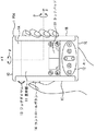
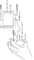
図1は、本発明を適用したPDA1をユーザが左手に保持している状態の正面(面1A)の外観構成の例を、図2は、PDA1の右側面(面1B)の外観構成の例を、それぞれ示す図である。
【0017】
PDA1は、片手で保持、および操作が可能な大きさに、その筐体が形成されており、面1Aのほぼ中央には、表示部11が設けられている。
【0018】
表示部11は、LCD(Liquid Crystal Display)等の表示装置で構成され、アイコン、サムネイル、またはテキストなどを表示する。
【0019】
ユーザは、表示部11に表示されるアイコンなどに対して、表示部11の下方に設けられているタッチパッド11A、タッチパッド11Aの下方に設けられているキー12、または面1C(左側面)に設けられているジョグダイヤル13などを操作して、各種指令を入力する。
【0020】
また、ユーザは、面1Cのジョグダイヤル13の下方に設けられているコントロールボタン14を筐体の内部方向に押下し、PDA1を傾けるなどして、各種処理を入力することができる。例えば、表示部11に、PDA1に記憶されているアプリケーションプログラムのメニュー画面が表示されている場合、ユーザは、PDA1を傾けることにより、カーソルを移動させ、実行するアプリケーションプログラムを選択することができる。
【0021】
さらに、PDA1を傾けるなどしてカーソルが移動された場合、カーソルの移動に併せて、振動が発生され、ユーザは、あたかもマウスポインタなどの入力装置によりアイコンを選択したようなクリック感(入力に対するフィードバック)を感じることができるようになされている。
【0022】
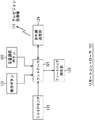
図3は、PDA1の電気的構成の例を示すブロック図である。図1と対応する部分については、同一の符号を付してあり、その説明は、適宜省略する。
【0023】
CPU(Central Processing Unit)31は、発振器32から供給されるクロック信号に同期して、Flash ROM(Read Only Memory)33、またはEDO DRAM(Extended Data Out Dynamic Random-Access Memory)34に格納されているオペレーティングシステム、またはアプリケーションプログラムなどの各種のプログラムを実行する。
【0024】
Flash ROM33は、EEPROM(Electrically Erasable Programmable Read-Only Memory)の一種であるフラッシュメモリで構成され、一般的には、CPU31が使用するプログラムや演算用のパラメータのうちの基本的に固定のデータを格納する。EDO DRAM34は、CPU31が実行するプログラムや、その実行において適宜変化するパラメータを格納する。
【0025】
メモリースティックインターフェース35は、PDA1に装着されているメモリースティック(商標)21からデータを読み出すとともに、CPU31から供給されたデータをメモリースティック21に書き込む。
【0026】
メモリースティック21は、小型薄型形状のプラスチックケース内に電気的に書換えや消去が可能なフラッシュメモリ素子を格納したものであり、10ピン端子を介して画像や音声、音楽等の各種データの書き込み及び読み出しが可能となっている。
【0027】
USB(Universal Serial Bus)インタフェース36は、発振器37から供給されるクロック信号に同期して、接続されているUSB機器からデータまたはプログラムを入力するとともに、CPU31から供給されたデータを出力する。
【0028】
Flash ROM33,EDO DRAM34、メモリースティックインタフェース35、およびUSBインタフェース36は、アドレスバスおよびデータバスを介して、CPU31に接続されている。
【0029】
表示部11は、LCDバスを介して、CPU31からデータを受信し、受信したデータに対応する画像または文字などを表示する。タッチパッド制御部38は、タッチパッド11Aが操作されたとき、操作に対応したデータ(例えば、タッチされた座標を示す)を表示部11から受信し、受信したデータに対応する信号をシリアルバスを介してCPU31に供給する。
【0030】
EL(Electroluminescence)ドライバ39は、表示部11の液晶表示部の裏側に設けられている電界発光素子を動作させ、表示部11の表示の明るさを制御する。
【0031】
赤外線通信部40は、UART(Universal Asynchronous Receiver-Transmitter)を介して、CPU31から受信したデータを赤外線信号として、図示せぬ他の機器に送信するとともに、他の機器から送信されてきた赤外線信号を受信して、CPU31に供給する。これにより、PDA1は、UARTを介して、他の機器と多方向に通信することができる。
【0032】
音声再生部41は、音声のデータの復号回路などから構成され、予め記憶している音声のデータ、または他の機器から受信した音声のデータなどを復号して、再生し、音声を出力する。例えば、音声再生部41は、内蔵するバッファを介してスピーカ42から、CPU31より供給された音声のデータを再生して、データに対応する音声を出力する。
【0033】
通信部43は、通信ケーブルなどを介して、インターネットなどと接続し、CPU31から供給されたデータ(例えば、電子メールなど)を、所定の方式のパケットに格納して、他の機器に送信する。また、通信部43は、他の機器から送信されてきたパケットに格納されているデータ、またはプログラムをCPU31に出力する。
【0034】
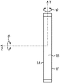
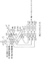
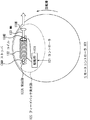
CPU31には、3軸ジャイロセンサ44の出力が、3軸ジャイロセンサインタフェース45を介して入力されている。3軸ジャイロセンサ44は、例えば、図4に示すように構成される。
【0035】
3軸ジャイロセンサ44は、図1に示すように、PDA1の面1Bに垂直な方向をX軸、面1D(上面)に垂直な方向をY軸、図2に示すように面1Aに垂直な方向をZ軸として、各座標軸に発生した回転角速度をそれぞれ検出する振動ジャイロ44A,44B,44Cから構成されている。
【0036】
振動ジャイロ44A乃至44Cは、振動している物体に回転角速度を加えると、その振動と直角方向にコリオリ力が生じる特性(コリオリ効果)を利用しており、このコリオリ力Fは、次のように表される。
【0037】
F=2mvω
(ただし、mは質量、vは速度、ωは角速度)
【0038】
従って、角速度ωは、コリオリ力Fに比例することになり、コリオリ力Fを検出することにより、回転角速度を検出することができる。
【0039】
振動ジャイロ44Aには、駆動用圧電磁器61Aと検出用圧電磁器61Bが設けられており、駆動用圧電磁器61Aにはオシレータ64Aの発振出力である交流信号が印加される。この状態で、X軸の回りに回転が加えられると、検出用圧電磁器61Bにコリオリ力Fが加わり、電圧Eが発生される。
【0040】
検出用圧電磁器61Bから出力される微小な電圧Eは、増幅器65Aにおいて増幅され、A/D変換器66Aでディジタルデータに変換される。
【0041】
変換されたディジタルデータは、3軸ジャイロセンサインタフェース45を介して、CPU31に通知される。
【0042】
なお、振動ジャイロ44Aに加わった角速度ωと、発生する電圧Eは、比例関係を有しており、例えば、X軸、Y軸、Z軸の交点(原点)に向かって、X軸の回りに右方向の回転が加えられたとき、電圧Eが上昇し、左方向の回転が加えられたとき、電圧Eが下降するように設定される。これにより、X軸の回りに加えられた、角速度の方向、および大きさが検出される。
【0043】
振動ジャイロ44B,44Cも、振動ジャイロ44Aと基本的に同様の構成とされる。すなわち、振動ジャイロ44BによってY軸の回りに発生する角速度が検出され、増幅器65Bにおいて増幅された後、A/D変換器66Bでディジタルデータに変換される。また、振動ジャイロ44Cによって、Z軸の回りに発生する角速度が検出され、増幅器65Cにおいて増幅された後、A/D変換器66Cでディジタルデータに変換される。
【0044】
A/D変換器66Bまたは66Cで変換されたディジタルデータは、振動ジャイロ44Aによって検出されたX軸の回りに発生した角速度のディジタルデータと同様に、3軸ジャイロセンサインタフェース45を介して、CPU31に通知される。
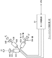
【0045】
CPU31は、フィードバック発生部46を制御する。このフィードバック発生部46は、図5に示されるように構成される。フィードバック発生部46は、基本的に、フィードバックを発生させる錘84A乃至84C、錘84A乃至84Cを、それぞれ回転させるモータ82A乃至82C、およびモータ82A乃至82Cのそれぞれに電圧を印加し、駆動させるモータ駆動部81から構成される。
【0046】
モータ駆動部81は、CPU31からの指示に基づいて、振動ジャイロ44Aが検出したX軸の回りに発生した角速度をうち消す方向に、錘84Aを回転させるべく、モータ82Aに対して電圧を印加する。
【0047】
また、モータ駆動部81は、モータ82Bおよび82Cについても同様に、振動ジャイロ44Bおよび44Cが検出した角速度をうち消す方向に、錘84Bおよび84Cのそれぞれを駆動させるべく、電圧を印加する。
【0048】
CPU31は、所定の閾値以上の角速度を検出することに応じて、表示部11に表示されているカーソルを移動させるとともに、錘84A乃至84Cを所定時間だけ急激に駆動させ、その後、急激に止める。そのため、PDA1を保持しているユーザは、PDA1を傾けてカーソルを移動させたことに対するクリック感などのフィードバックを感じることができる。
【0049】
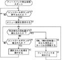
次に、図6のフローチャートを参照して、ユーザがPDA1を傾けることにより操作する場合に発生させる、PDA1のフィードバック発生処理について説明する。また、説明において、図7乃至図10に示す表示部11の表示例が適宜参照される。
【0050】
ステップS1において、CPU31は、コントロールボタン14が押下されたか否かを判定し、押下されたと判定するまで待機する。PDA1において、ユーザは、コントロールボタン14を押下している間、PDA1を傾けることによりカーソルを移動させることができる。
【0051】
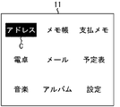
CPU31は、コントロールボタン14が押下されたと判定した場合、ステップS2に進み、Flash ROM33等に記憶されているアプリケーションプログラムの選択メニュー画面を表示部11に表示させる。
【0052】
図7は、ステップS2の処理において、CPU31が表示部11に表示させるアプリケーションプログラムの選択メニュー画面の例を示す図である。
【0053】
この例においては、アドレスプログラムを実行するとき操作される「アドレスアイコン」、メモ帳プログラムを実行するとき操作される「メモ帳アイコン」、支払メモプログラムを実行するとき操作される「支払メモアイコン」、電卓プログラムを実行するとき操作される「電卓アイコン」、メールプログラムを実行するとき操作される「メールアイコン」、予定表プログラムを実行するとき操作される「予定表アイコン」、音楽プログラムを実行するとき操作される「音楽アイコン」、アルバムプログラムを実行するとき操作される「アルバムアイコン」、設定プログラムを実行するとき操作される「設定アイコン」が表示されている。
【0054】
また、プログラムを指定するカーソルCが、「アドレスアイコン」の上に表示されており、ユーザは、PDA1を傾けることにより、このカーソルCを移動させ、実行するプログラムを選択する。
【0055】
ステップS3において、CPU31は、所定単位の回転量が算出されたか否かを、3軸ジャイロセンサ44からの通知に基づいて判定する。すなわち、CPU31は、3軸ジャイロセンサ44から通知される角速度と、回転が加えられた時間とを乗算することにより、回転量を算出し、それが所定単位の回転量を超えたか否かを判定する。
【0056】
CPU31は、所定単位以上の回転量を算出していないと判定した場合、ステップS4の処理に進み、コントロールボタン14が離されたか否かを判定する。
【0057】
CPU31は、コントロールボタン14が離されていないと判定した場合、ステップS3に戻り、それ以降の処理を繰り返し実行する。
【0058】
一方、CPU31は、ステップS4において、コントロールボタン14がユーザにより離されたと判定した場合、ステップS5に進み、選択された処理(アプリケーションプログラム)を実行する。例えば、アプリケーションプログラムの選択メニュー画面が図7に示す状態において、コントロールボタン14が離された場合、CPU31は、アドレスプログラムが選択されたと認識し、アドレスプログラムをEDO RAM34に展開し、起動させる。
【0059】
その後、処理は、ステップS1に戻り、それ以降の処理が繰り返し実行される。
【0060】
一方、ステップS3において、CPU31は、所定単位の回転量を算出したと判定した場合、ステップS6に進み、算出したX軸、およびY軸の回りに発生した回転量に応じて、表示部11に表示されているカーソルCを移動させる。
【0061】
また、CPU31は、ステップS6の処理でカーソルCを移動させるのと同時に、ステップS7において、フィードバック発生部46に対して、算出された回転量をうち消す方向に、錘84Aまたは84Bを回転させることにより、フィードバックを発生することを指示する。
【0062】
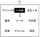
例えば、カーソルCが図7に示すように「アドレスアイコン」を示している状態において、ユーザがPDA1を図1に示す状態(水平な状態)から、Y軸を中心として、面1Bの方向(右方向)に、所定の角度だけ傾けた場合、ステップS3の処理でCPU31は、3軸ジャイロセンサ44からの通知に基づいてY軸の回りに所定単位の回転量を算出したと判定し、ステップS6の処理で図8に示す表示例のように、カーソルCを右方向に移動させる。
【0063】
図8の表示部11の表示例においては、「アドレスアイコン」を指定していたカーソルCが、Y軸の回りに発生した回転量に応じて移動し、1つ右側のアイコンである「メモ帳アイコン」を指定する状態とされている。また、CPU31は、このアイコンの移動に併せて、ステップS7の処理で、モータ駆動部81(図5)に対して、加えられた回転をうち消す方向(図1において面1Cの方向(左方向))にモータ82Bを急激に駆動させることを指示する。これにより、ユーザは、カーソルCが1つ右側のアイコンに移動したことを、視覚だけでなく、触覚で感じることができる。
【0064】
その後、処理はステップS3に戻り、それ以降の処理が繰り返し実行される。すなわち、CPU31は、ユーザがコントロールボタン14を離して、実行する処理を確定するまで、所定単位以上の回転量が加えられたと判定する毎に、カーソルCを対応する方向に移動させ、それとともにフィードバックを発生させる。
【0065】
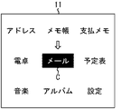
図9は、図8に示すカーソルCの位置において、ユーザがPDA1を、図1に示す水平な状態から、X軸を中心として、面1E(底面)の方向(下方向)に傾けることにより、さらに、X軸の回りに回転が加えられたときのカーソルCの移動を示す図である。すなわち、この場合、CPU31は、ステップS6において、「メモ帳アイコン」から「メールアイコン」の上に、カーソルCを移動させる。また、CPU31は、ステップS7において、モータ駆動部81に対して、加えられた回転をうち消す方向(図1において面1D(上面)の方向(上方向))にモータ82Aを駆動させることを指示し、フィードバックを発生させる。
【0066】
以上の処理により、ユーザは、PDA1を傾けることによりカーソルCを移動させることができ、それとともにクリック感(フィードバック)を感じることができるため、より確実に、実行する処理を選択することができる。
【0067】
また、PDA1において発生されるフィードバックは、モータ84A乃至84Cの回転により発生させるのではなく、ピエゾ素子などにより発生させるようにしてもよい。
【0068】
図10は、面1Cにピエゾ素子91が配列して設けられている場合の、PDA1の外観構成の例を示す図である。また、面1Bにも、ピエゾ素子が同様に配列して設けられる。
【0069】
ピエゾ素子91は、電気機械結合係数が高いセラミック(例えば、PZT(チタン酸ジルコン酸鉛))から構成されており、電圧が印加された場合、厚み方向(面1B,1Cと垂直な方向)に瞬時に歪んで、変位を発生する薄板状の素子である。
【0070】
各ピエゾ素子91のそれぞれにより発生される変位は、PDA1を保持しているユーザが、手に触覚として認識できる変位とされる。変位量は、ピエゾ素子91に印加する電圧を調整することにより、または、セラミック素子の積層枚数を調整することにより設定される。なお、ピエゾ素子91の表面は、アクリル樹脂等からなる保護層で覆われている。
【0071】
これにより、クリック感を発生させることができ、ユーザは、フィードバックを感じることができる。この場合、図3のフィードバック発生部46は、ピエゾ素子91と、ピエゾ素子91のそれぞれに対して電圧を印加するピエゾ素子駆動部から構成される。このように、様々な方法により、フィードバックを発生させることができる。
【0072】
以上においては、X軸、およびY軸の回りに発生した回転量に応じて、カーソルを移動させ、フィードバックを発生させることとしたが、PDA1に加えられた様々な変位に応じて、フィードバックを発生させることができる。
【0073】
例えば、ユーザは、コントロールボタン14を押下して、その位置を基準として、PDA1をZ軸の方向(図1において、紙面と垂直な上方向)に移動させることにより、表示部11に表示されている画像を拡大表示させることもできる。また、ユーザは、逆に、図1において、紙面と垂直な下方向にPDA1を移動させることにより、表示部11に表示されている画像を縮小表示させることができる。この場合、CPU31は、拡大、または縮小表示する毎に、フィードバックを発生させる。
【0074】
また、あたかもドラム上に各アプリケーションプログラムが配置されるように選択メニュー画面が表示されている場合、ユーザは、コントロールボタン14を押下し、PDA1をX軸を中心として回転させることにより、アプリケーションプログラムを選択することができる。この場合、アプリケーションプログラムが切り替わる毎にフィードバックが発生される。
【0075】
図11は、テレビジョン受像機111を赤外線信号により操作するリモートコントローラ101に本発明を適用した場合の構成例を示す図である。
【0076】
リモートコントローラ101は、円盤状の筐体を有しており、面101A、および面101Bには、各種入力ボタンが配置される。また、面101Aの裏側の面101Cには、赤外線送信部124(図12)が設けられており、ユーザにより入力された各種処理が赤外線信号として、テレビジョン受像機111に対して送出される。
【0077】
面101B(側面)には、音量調節ボタン102が配置されており、ユーザは面101C(背面)をテレビジョン受像機111に向けた状態で、音量調節ボタン102を押しながらリモートコントローラ101を時計回転方向、または反時計回転方向に回転させることにより、音量を調節することができる。
【0078】
なお、テレビジョン受像機111には、正面にCRT112が、その両側にスピーカ113Aおよび113Bが、CRT112の下方に操作パネル114および赤外線受信部115が、それぞれ設けられている。
【0079】
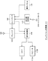
図12は、リモートコントローラ101の内部構成の例を示すブロック図である。
【0080】
コントローラ121は、リモートコントローラ101の全体の動作を制御し、リモートコントローラ101に設けられる各種の操作ボタン122、および音量調節ボタン102が、ユーザにより操作されることに応じて、その処理を実行する。
【0081】
ジャイロセンサ123は、面101A(正面)に垂直な方向の軸の回りに発生した角速度を検出し、コントローラ121に通知する。コントローラ121は、その通知に基づいて、リモートコントローラ101に加えられた回転量を算出する。
【0082】
赤外線送信部124は、コントローラ121からの指示に基づいて、図示せぬ発光ダイオードを駆動させ、テレビジョン受像機111に対して赤外線信号を送出する。
【0083】
フィードバック発生部125は、コントローラ121からの指示に基づいて、ユーザに対するフィードバックを発生させる。フィードバック発生部125は、例えば、図13および図14に示す例のように構成される。
【0084】
この例においては、図13および図14に示すように、中空状のコイル132、ストッパ134Aおよび134Bは、図示せぬ基板上に固定されており、その中を左右方向に駆動自在に、軸133が設けられている。
【0085】
フィードバック発生部125は、例えば、図13に示すように、左方向(反時計回転方向)の回転が加えられ、それが所定単位を超えたとコントローラ121により判定された場合、その回転をうち消す方向(右方向)に、軸133を移動させるようにコイル132が駆動される。これにより、軸133の突起部133Aが、ストッパ134Aと衝突したとき、ユーザに対するフィードバックが発生される。
【0086】
また、図14に示すように、フィードバック発生部125は、反対に、右方向(時計回転方向)に所定単位以上の回転量が加えられたとき、軸133を左方向に移動させ、その突起部134Bをストッパ134Bに衝突させ、フィードバックを発生させる。
【0087】
なお、駆動部131は、コントローラ121からの指示に基づいて、コイル132に対して印加する電圧の極性を変化させることにより、軸133の移動方向を制御する。
【0088】
このような構成により、フィードバック発生部125により発生されるフィードバックは、例えば、オーディオシステムに設けられるクリック機能付きの音量調節つまみを、ユーザがあたかも回しているようなフィードバックとされる。
【0089】
図15は、テレビジョン受像機111の内部構成の例を示すブロック図である。図11に示した部分については、同一の符号を付してある。
【0090】
コントローラ141は、テレビジョン受像機111の全体の動作を制御し、赤外線受信部115において受信された赤外線信号、または操作パネル114により、ユーザから指示された各種処理を実行する。
【0091】
チューナ142は、コントローラ121により制御され、アンテナ143で受信された放送波から、ユーザが視聴することを希望するチャンネルの信号を選択し、信号処理部144に供給する。
【0092】
信号処理部144は、チューナ142から供給されてきた信号を復調処理し、ビデオ信号をCRT112に、オーディオ信号をスピーカ113Aおよび113Bに、それぞれ出力する。また、信号処理部144は、コントローラ141から制御され、例えば、音量表示などの画像をCRT112に表示させる。
【0093】
次に、図16のフローチャートを参照して、ユーザが音量を調節する場合の、リモートコントローラ101のフィードバック発生処理について説明する。
【0094】
ステップS21において、コントローラ121は、面101Bに設けられている音量調節ボタン102が押下されたか否かを判定し、押下されたと判定するまで待機する。
【0095】
コントローラ121は、音量調節ボタン102がユーザにより押下されたと判定した場合、ステップS22に進み、音量調節の開始を指令する赤外線信号を赤外線送信部124から送信する。これに応じて、テレビジョン受像機111のCRT112に、現在の音量を示す画像が表示される(後述する図17のステップS42の処理)。
【0096】
ステップS23において、コントローラ121は、ジャイロセンサ123からの通知に基づいて、リモートコントローラ101に加えられた回転量を算出し、所定単位を超えたか否かを判定する。
【0097】
コントローラ121は、所定単位以上の回転を算出していないと判定した場合、ステップS24の処理に進み、音量調節ボタン102が離されたか否かを判定する。
【0098】
コントローラ121は、ステップS24で、ユーザが音量調節ボタン102を離していないと判定した場合、ステップS23に戻り、それ以降の処理を繰り返し実行する。また、コントローラ121は、ステップS24で、ユーザが音量調節ボタン102を離したと判定した場合、ステップS21に戻り、それ以降の処理を繰り返し実行する。
【0099】
一方、ステップS23において、コントローラ121は、ジャイロセンサ123からの通知に基づいて、所定単位以上の回転がリモートコントローラ101に加えられたと判定した場合、ステップS25の処理に進む。
【0100】
ステップS25において、コントローラ121は、赤外線送信部124を制御し、テレビジョン受像機111に対する音量調節信号を、赤外線信号として送出する。例えば、面101Cをテレビジョン受像機111に向けた状態で、リモートコントローラ101に右方向(時計回転方向)に所定単位だけ回転が加えられた場合、「音量を1単位上げる」と、逆に、左方向(反時計回転方向)に所定単位だけ回転が加えられた場合、「音量を1単位下げる」と、それぞれ設定されているとすると、コントローラ121は、ユーザから加えられた回転に応じて、音量を1段階上げるか、または下げることを指示する音量調節信号を送出する。
【0101】
テレビジョン受像機111は、この音量調節信号に応じて音量を調節し、それとともに、CRT112に表示されている音量表示画像を変更させる(図17のステップS46およびS47の処理)。
【0102】
コントローラ121は、ステップS25の処理で音量調節信号を送信すると同時に、ステップS26において、フィードバック発生部125を制御し、ユーザに対するフィードバックを発生させる。例えば、図13に示すように、面101Cをテレビジョン受像機111に向けた状態で、反時計回転方向に回転が加えられたと判定した場合、駆動部131は、軸133を右方向に移動させるように、コイル133に対して電圧を印加し、フィードバックを発生させる。
【0103】
その後、処理はステップS23に戻り、それ以降の処理が繰り返し実行される。すなわち、ユーザは、音量調節ボタン102を押下している間、音量を複数段階調節することができ、音量を1段階調節する毎に、音量調節つまみを回しているかのような触覚を感じることができる。
【0104】
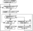
次に、図17のフローチャートを参照して、リモートコントローラ101からの信号に基づいて、音量調節するテレビジョン受像機111の処理について説明する。
【0105】
ステップS41において、テレビジョン受像機111のコントローラ141は、音量調節開始の信号が赤外線受信部115において受信されたか否かを判定し、リモートコントローラ101から音量調節開始の信号が送信され、赤外線受信部115において受信されたと判定するまで待機する。
【0106】
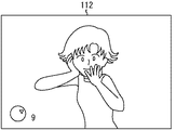
コントローラ141は、音量調節開始の赤外線信号がリモートコントローラ101から送信されてきたと判定した場合、ステップS42に進み、音量調節つまみをCRT112に表示させる。
【0107】
図18は、ステップS42の処理で表示されるCRT112の表示例を示す図である。この例においては、CRT112の中央に、チューナ142が選局している番組の画像が表示され、CRT112の左隅に、音量調節つまみと、そのつまみが示す現在の音量レベルを表す数字(図18の例の場合、9)が表示されている。
【0108】
ステップS43において、コントローラ141は、実際に音量を変更する音量調節信号が、赤外線受信部115において受信されたか否かを判定し、受信されていないと判定した場合、ステップS44に進む。
【0109】
ステップS44において、コントローラ141は、音量調節開始の信号が受信されてから、所定時間が経過したか否かを判定し、所定時間が経過していないと判定した場合、ステップS43に戻り、それ以降の処理を繰り返し実行する。
【0110】
ステップS44において、コントローラ141は、音量調節開始の信号を受信してから所定時間が経過したと判定した場合、ステップS45に進み、CRT112に表示されている音量調節つまみの画像を消し、その後、ステップS41に戻り、それ以降の処理を繰り返し実行する。
【0111】
一方、ステップS43において、コントローラ141は、音量を変更する音量調節信号が赤外線受信部115において受信されたと判定した場合、ステップS46に進む。
【0112】
ステップS46において、コントローラ141は、リモートコントローラ101から送信されてきた音量調節信号に基づいて音量を調節する。例えば、現在のCRT112の表示が図18に示されるような場合において、リモートコントローラ101から、音量を1段階上げることを指示する音量調節信号が送信されてきたとき、コントローラ141は、スピーカ113Aおよび113Bに出力する音量を1段階上げるとともに、図19に示すCRT112の表示例のように、音量調節つまみの方向を1段階だけ右方向に回転させ、現在の音量レベルを表す数字を10と表示させる。
【0113】
その後、処理はステップS43に戻り、それ以降の処理が繰り返し実行される。
【0114】
以上においては、リモートコントローラ101が所定の量だけ回転されたときフィードバックが発生されるようにしたが、リモートコントローラ101が所定の量だけ回転されたとき、対応する信号をテレビジョン受像機111に送信させるが、フィードバックは発生させず、テレビジョン受像機111が、その信号に対応して、音量を所定の値に設定したとき、それを表す信号をテレビジョン受像機111からリモートコントローラ101に送信させ、リモートコントローラ101がそれを受信したとき、フィードバックを発生させるようにしてもよい。この場合、リモートコントローラ101の赤外線送信部124と、テレビジョン受像機111の赤外線受信部115は、それぞれ、赤外線信号の送受信が可能な赤外線通信部により構成される。
【0115】
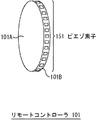
また、以上においては、音量調節つまみを回しているかのようなフィードバックは、コイル132や、軸133等により発生されるとしたが、上述したPDA1の場合と同様に、図20に示されるように、ピエゾ素子151により発生させるなど、さまざまな方法により発生させるようにしてもよい。
【0116】
図20においては、ピエゾ素子151が面101Bに配列して設けられており、ユーザがリモートコントローラ101を回転させて音量を調節する場合、ピエゾ素子151が駆動され、音量調節つまみを回しているかのようなフィードバックが発生される。
【0117】
なお、この場合、図12に示すフィードバック発生部125は、ピエゾ素子151と、ピエゾ素子151に対して電圧を印加する駆動部より構成される。
【0118】
以上においては、PDA1やテレビジョン受像機111のリモートコントローラ101に本発明を適用したが、本発明は、ユーザの体と接触するものであれば、他の様々な情報処理端末、および入力装置に適用できる。
【0119】
【発明の効果】
本発明によれば、操作性の良好なユーザインタフェースを実現することができる。
【図面の簡単な説明】
【図1】本発明を適用したPDAの正面の外観構成を示す図である。
【図2】図1のPDAの右側面の外観構成を示す図である。
【図3】図1のPDAの内部構成を示すブロック図である。
【図4】図3の3軸ジャイロセンサの構成例を示す図である。
【図5】図3のフィードバック発生部の構成例を示す図である。
【図6】図1のPDAの処理を説明するフローチャートである。
【図7】図1のPDAの表示部の表示例を示す図である。
【図8】図1のPDAの表示部の他の表示例を示す図である。
【図9】図1のPDAの表示部のさらに他の表示例を示す図である。
【図10】本発明を適用したPDAの他の外観構成を示す図である。
【図11】本発明を適用したリモートコントローラの外観構成を示す図である。
【図12】図11のリモートコントローラの内部構成を示すブロック図である。
【図13】図12のフィードバック発生部の構成例を示す図である。
【図14】図12のフィードバック発生部の他の構成例を示す図である。
【図15】図11のテレビジョン受像機の内部構成を示すブロック図である。
【図16】図11のリモートコントローラの処理を説明するフローチャートである。
【図17】図11のテレビジョン受像機の処理を説明するフローチャートである。
【図18】図11のテレビジョン受像機の表示例を示す図である。
【図19】図11のテレビジョン受像機の他の表示例を示す図である。
【図20】本発明を適用したリモートコントローラの他の外観構成を示す図である。
【符号の説明】
1 PDA, 11 表示部, 14 コントロールボタン, 31 CPU, 33 Flash ROM, 34 EDO DRAM, 38 タッチパッド制御部, 44 3軸ジャイロセンサ, 45 3軸ジャイロセンサインタフェース, 46 フィードバック発生部, 91 ピエゾ素子, 101 リモートコントローラ, 102 音量調節ボタン, 121 コントローラ, 123 ジャイロセンサ, 125 フィードバック発生部, 151 ピエゾ素子[0001]
BACKGROUND OF THE INVENTION
The present invention relates to an information processing apparatus and method, and more particularly, to an information processing apparatus and method capable of realizing a more preferable user interface by generating vibration in response to detection of a predetermined displacement.
[0002]
[Prior art]
In recent years, as a user interface of an information processing terminal such as a mobile phone or PDA (Personal Digital Assistants), it has been proposed to input various processes by rotating or tilting the terminal.
[0003]
For example, when a menu screen of an application program is displayed on the terminal, the cursor on the screen moves as the user tilts the terminal so that the desired application program can be selected.
[0004]
[Problems to be solved by the invention]
However, when the user moves the cursor by tilting the terminal or the like, there is a problem that the operation is difficult because a delicate tilt adjustment is required.
[0005]
The present invention has been made in view of such a situation, and is intended to provide a user interface that can be input easily and reliably on a terminal in which a cursor moves in accordance with an inclination or the like.
[0006]
[Means for Solving the Problems]
An information processing terminal according to the present invention includes an execution unit that executes predetermined processing, a displacement detection unit that detects a displacement of the posture of the casing of the information processing terminal, and a displacement of the posture detected by the displacement detection unit. When the value is exceeded,Driving means for generating feedback in a direction that cancels the displacement of postureIt is characterized by providing.
[0007]
Display means for displaying a plurality of information;DriveBy meansFeedback is generatedIn addition, display switching means for switching the display of information displayed by the display means can be further provided.
[0008]
The information processing apparatus may further include an instruction unit that instructs execution of the information switched by the display switching unit, and the execution unit may execute processing corresponding to the information instructed by the instruction unit.
[0009]
The displacement detection means can detect a displacement of rotation about a predetermined axis of the housing.
The driving means includes a weight, and generates feedback by rotating the weight in a direction that cancels the angular velocity of rotation detected by the displacement detecting means.
[0010]
The display switching means can enlarge or reduce the information displayed by the display means.
[0011]
Protruding from the housing,Generate vibrations transmitted to the user's handA vibration generating means can be further provided. In this case, the driving means drives the vibration generating means to generate feedback..
[0012]
The information processing terminal is an input device of another information processing apparatus, and may further include a transmission unit that transmits an instruction to the other information processing apparatus.
[0013]
Receiving means for receiving a signal from another information processing apparatusWhen,Vibration is generated in the housing according to the signal received by the receiving means.A vibration generating means can be further provided. The driving means drives the vibration generating means to generate feedback.be able to.
[0014]
The information processing method of the information processing terminal according to the present invention includes an execution step for executing a predetermined process, a displacement detection step for detecting a displacement of the attitude of the housing of the information processing terminal, and a posture detected by the processing of the displacement detection step. When the displacement of exceeds a predetermined value,Drive that generates feedback in a direction that cancels the displacement of the postureAnd a step.
[0015]
In the information processing terminal and method of the present invention, predetermined processing is executed, and the displacement of the attitude of the casing of the information processing terminal is detected. In addition, when the detected displacement of the posture exceeds a predetermined value,Feedback is generated in a direction that cancels the displacement of the posture.
[0016]
DETAILED DESCRIPTION OF THE INVENTION
FIG. 1 shows an example of the external configuration of the front surface (
[0017]
The housing of the
[0018]
The
[0019]
For an icon or the like displayed on the
[0020]
In addition, the user can input various processes by pressing the
[0021]
Furthermore, when the cursor is moved by tilting the
[0022]
FIG. 3 is a block diagram illustrating an example of the electrical configuration of the
[0023]
A CPU (Central Processing Unit) 31 is stored in a Flash ROM (Read Only Memory) 33 or an EDO DRAM (Extended Data Out Dynamic Random Access Memory) 34 in synchronization with a clock signal supplied from an
[0024]
The Flash
[0025]
The
[0026]
The
[0027]
A USB (Universal Serial Bus)
[0028]
The
[0029]
The
[0030]
An EL (Electroluminescence)
[0031]
The
[0032]
The audio reproduction unit 41 includes an audio data decoding circuit and the like, and decodes and reproduces audio data stored in advance or audio data received from another device, and outputs audio. For example, the audio reproduction unit 41 reproduces audio data supplied from the
[0033]
The
[0034]
The output of the 3-
[0035]
As shown in FIG. 1, the
[0036]
The vibrating
[0037]
F = 2mvω
(Where m is mass, v is velocity, ω is angular velocity)
[0038]
Therefore, the angular velocity ω is proportional to the Coriolis force F, and the rotational angular velocity can be detected by detecting the Coriolis force F.
[0039]
The
[0040]
The minute voltage E output from the detection piezoelectric ceramic 61B is amplified by the
[0041]
The converted digital data is notified to the
[0042]
Note that the angular velocity ω applied to the
[0043]
The
[0044]
The digital data converted by the A /
[0045]
The
[0046]
Based on an instruction from the
[0047]
Similarly, the
[0048]
The
[0049]
Next, a feedback generation process of the
[0050]
In step S1, the
[0051]
If the
[0052]
FIG. 7 is a diagram showing an example of an application program selection menu screen that the
[0053]
In this example, an “address icon” operated when executing the address program, a “notepad icon” operated when executing the notepad program, and a “payment memo icon” operated when executing the payment memo program. , "Calculator icon" operated when running the calculator program, "Mail icon" operated when running the mail program, "Calendar icon" operated when running the calendar program, Execute music program A “music icon” that is operated when the album program is executed, an “album icon” that is operated when the album program is executed, and a “setting icon” that is operated when the setting program is executed are displayed.
[0054]
A cursor C for designating a program is displayed on the “address icon”, and the user moves the cursor C by tilting the
[0055]
In step S <b> 3, the
[0056]
If the
[0057]
If the
[0058]
On the other hand, if the
[0059]
Thereafter, the process returns to step S1, and the subsequent processes are repeatedly executed.
[0060]
On the other hand, if it is determined in step S3 that the
[0061]
At the same time as moving the cursor C in the process of step S6, the
[0062]
For example, in a state where the cursor C indicates an “address icon” as shown in FIG. 7, the user moves the
[0063]
In the display example of the
[0064]
Thereafter, the process returns to step S3, and the subsequent processes are repeatedly executed. That is, every time the
[0065]
9 shows that the user tilts the
[0066]
With the above processing, the user can move the cursor C by tilting the
[0067]
Further, the feedback generated in the
[0068]
FIG. 10 is a diagram showing an example of the external configuration of the
[0069]
The piezo element 91 is made of a ceramic having a high electromechanical coupling coefficient (for example, PZT (lead zirconate titanate)), and in the thickness direction (direction perpendicular to the
[0070]
The displacement generated by each of the piezo elements 91 is a displacement that the user holding the
[0071]
Thereby, a click feeling can be generated and the user can feel feedback. In this case, the
[0072]
In the above, the cursor is moved according to the amount of rotation generated around the X axis and the Y axis, and feedback is generated. However, feedback is generated according to various displacements applied to the
[0073]
For example, when the user presses the
[0074]
Further, when the selection menu screen is displayed so that each application program is arranged on the drum, the user presses the
[0075]
FIG. 11 is a diagram illustrating a configuration example when the present invention is applied to the
[0076]
The
[0077]
[0078]
The television receiver 111 is provided with a
[0079]
FIG. 12 is a block diagram illustrating an example of the internal configuration of the
[0080]
The
[0081]
The
[0082]
The
[0083]
The
[0084]
In this example, as shown in FIGS. 13 and 14, the
[0085]
For example, as shown in FIG. 13, the
[0086]
Also, as shown in FIG. 14, the
[0087]
The
[0088]
With such a configuration, the feedback generated by the
[0089]
FIG. 15 is a block diagram illustrating an example of the internal configuration of the television receiver 111. The parts shown in FIG. 11 are given the same reference numerals.
[0090]
The
[0091]
The
[0092]
The
[0093]
Next, feedback generation processing of the
[0094]
In step S21, the
[0095]
When it is determined that the
[0096]
In step S23, the
[0097]
If the
[0098]
If the
[0099]
On the other hand, if the
[0100]
In step S <b> 25, the
[0101]
The television receiver 111 adjusts the volume according to the volume adjustment signal, and changes the volume display image displayed on the CRT 112 (steps S46 and S47 in FIG. 17).
[0102]
The
[0103]
Thereafter, the processing returns to step S23, and the subsequent processing is repeatedly executed. That is, the user can adjust the volume in a plurality of levels while pressing the
[0104]
Next, processing of the television receiver 111 that adjusts the volume based on a signal from the
[0105]
In step S41, the
[0106]
If the
[0107]
FIG. 18 is a diagram showing a display example of the
[0108]
In step S43, the
[0109]
In step S44, the
[0110]
In step S44, if the
[0111]
On the other hand, when the
[0112]
In step S <b> 46, the
[0113]
Thereafter, the processing returns to step S43, and the subsequent processing is repeatedly executed.
[0114]
In the above, feedback is generated when the
[0115]
In the above description, feedback as if the volume control knob is being turned is generated by the
[0116]
In FIG. 20, the piezo elements 151 are arranged on the
[0117]
In this case, the
[0118]
In the above, the present invention is applied to the
[0119]
【The invention's effect】
The present inventionAccording toA user interface with good operability can be realized.
[Brief description of the drawings]
FIG. 1 is a diagram showing an external configuration of a front surface of a PDA to which the present invention is applied.
2 is a diagram showing an external configuration of a right side surface of the PDA in FIG. 1;
3 is a block diagram showing an internal configuration of the PDA of FIG.
4 is a diagram illustrating a configuration example of the three-axis gyro sensor in FIG. 3. FIG.
FIG. 5 is a diagram illustrating a configuration example of a feedback generation unit in FIG. 3;
6 is a flowchart for explaining processing of the PDA in FIG. 1; FIG.
7 is a diagram showing a display example of the display unit of the PDA in FIG. 1. FIG.
8 is a diagram showing another display example of the display unit of the PDA of FIG. 1. FIG.
9 is a diagram showing still another display example of the display unit of the PDA in FIG. 1. FIG.
FIG. 10 is a diagram showing another external configuration of a PDA to which the present invention is applied.
FIG. 11 is a diagram showing an external configuration of a remote controller to which the present invention is applied.
12 is a block diagram showing an internal configuration of the remote controller of FIG. 11. FIG.
13 is a diagram illustrating a configuration example of a feedback generation unit in FIG. 12;
14 is a diagram illustrating another configuration example of the feedback generation unit in FIG. 12;
15 is a block diagram showing an internal configuration of the television receiver of FIG. 11. FIG.
16 is a flowchart illustrating processing of the remote controller in FIG.
FIG. 17 is a flowchart for explaining processing of the television receiver in FIG. 11;
18 is a diagram showing a display example of the television receiver in FIG. 11. FIG.
FIG. 19 is a diagram showing another display example of the television receiver in FIG. 11;
FIG. 20 is a diagram showing another external configuration of a remote controller to which the present invention is applied.
[Explanation of symbols]
1 PDA, 11 display section, 14 control buttons, 31 CPU, 33 Flash ROM, 34 EDO DRAM, 38 touch pad control section, 44 3-axis gyro sensor, 45 3-axis gyro sensor interface, 46 feedback generation section, 91 piezo element, 101 remote controller, 102 volume control button, 121 controller, 123 gyro sensor, 125 feedback generator, 151 piezo element
Claims (10)
所定の処理を実行する実行手段と、
前記情報処理端末の筐体の姿勢の変位を検出する変位検出手段と、
前記変位検出手段により検出された前記姿勢の変位が、所定の値を超えたとき、前記姿勢の変位を打ち消す方向にフィードバックを発生させる駆動手段と
を備える情報処理端末。In an information processing terminal possessed and used by the user's hand,
Execution means for executing predetermined processing;
A displacement detecting means for detecting a displacement of a posture of the casing of the information processing terminal;
The displacement of the posture detected by the displacement detecting means, when exceeding a predetermined value, the information processing terminal Ru and drive means for generating the feedback in a direction to cancel the displacement of the posture.
前記駆動手段により前記フィードバックが発生されることに併せて、前記表示手段により表示される前記情報の表示を切り替える表示切替手段と
をさらに備える請求項1に記載の情報処理端末。Display means for displaying a plurality of information;
The feedback together that is generated, the information processing terminal according to claim 1, further Ru and a display switching means for switching the display of information displayed by said display means by said driving means.
前記実行手段は、前記指示手段により指示された前記情報に対応する処理を実行する
請求項2に記載の情報処理端末。An instruction means for instructing execution of the information switched by the display switching means;
The execution unit executes a process corresponding to the information instructed by the instruction unit
The information processing terminal according to claim 2 .
請求項1に記載の情報処理端末。The displacement detection means detects a displacement of rotation with respect to a predetermined axis of the casing.
The information processing terminal according to claim 1.
請求項4に記載の情報処理端末。 The information processing terminal according to claim 4.
請求項2に記載の情報処理端末。The display switching means enlarges or reduces the information displayed by the display means.
The information processing terminal according to claim 2 .
前記駆動手段は、前記振動発生手段を駆動させて、前記フィードバックを発生する
請求項1に記載の情報処理端末。Wherein it protrudes from the housing, further comprising a vibration generating means for generating vibrations transmitted to the hand of the user,
The driving means drives the vibration generating means to generate the feedback.
The information processing terminal according to claim 1.
前記他の情報処理装置に対する指示を送信する送信手段をさらに備える
請求項1に記載の情報処理端末。The information processing terminal is an input device of another information processing device,
The apparatus further comprises a transmission means for transmitting an instruction to the other information processing apparatus
The information processing terminal according to claim 1.
前記受信手段により受信された信号に応じて、前記筐体に振動を発生する振動発生手段と
をさらに備え、
前記駆動手段は、前記振動発生手段を駆動させて、前記フィードバックを発生する
請求項8に記載の情報処理端末。Receiving means for receiving a signal from the other information processing apparatus ;
Vibration generating means for generating vibration in the housing in response to a signal received by the receiving means;
Further comprising
The driving means drives the vibration generating means to generate the feedback.
The information processing terminal according to claim 8 .
所定の処理を実行する実行ステップと、
前記情報処理端末の筐体の姿勢の変位を検出する変位検出ステップと、
前記変位検出ステップの処理により検出された前記姿勢の変位が、所定の値を超えたとき、前記姿勢の変位を打ち消す方向にフィードバックを発生させる駆動ステップと
を含む情報処理方法。In the information processing method of the information processing terminal possessed and used by the user's hand,
An execution step for executing a predetermined process;
A displacement detection step of detecting a displacement of a posture of the casing of the information processing terminal;
The displacement of the posture detected by the processing of the displacement detecting step, when exceeding a predetermined value, including an information processing method and a driving step of generating a feedback in a direction to cancel the displacement of the posture.
Priority Applications (6)
| Application Number | Priority Date | Filing Date | Title |
|---|---|---|---|
| JP2001002276A JP4635342B2 (en) | 2001-01-10 | 2001-01-10 | Information processing terminal and method |
| PCT/JP2002/000008 WO2002056165A1 (en) | 2001-01-10 | 2002-01-07 | Information processing terminal |
| US10/250,879 US7230605B2 (en) | 2001-01-10 | 2002-01-07 | Information processing terminal |
| EP02729371A EP1351119A4 (en) | 2001-01-10 | 2002-01-07 | INFORMATION PROCESSING TERMINAL |
| CNB028035879A CN1258703C (en) | 2001-01-10 | 2002-01-07 | Information processing terminal |
| KR1020037009095A KR100787792B1 (en) | 2001-01-10 | 2002-01-07 | Information processing terminal |
Applications Claiming Priority (1)
| Application Number | Priority Date | Filing Date | Title |
|---|---|---|---|
| JP2001002276A JP4635342B2 (en) | 2001-01-10 | 2001-01-10 | Information processing terminal and method |
Publications (2)
| Publication Number | Publication Date |
|---|---|
| JP2002207567A JP2002207567A (en) | 2002-07-26 |
| JP4635342B2 true JP4635342B2 (en) | 2011-02-23 |
Family
ID=18870814
Family Applications (1)
| Application Number | Title | Priority Date | Filing Date |
|---|---|---|---|
| JP2001002276A Expired - Fee Related JP4635342B2 (en) | 2001-01-10 | 2001-01-10 | Information processing terminal and method |
Country Status (6)
| Country | Link |
|---|---|
| US (1) | US7230605B2 (en) |
| EP (1) | EP1351119A4 (en) |
| JP (1) | JP4635342B2 (en) |
| KR (1) | KR100787792B1 (en) |
| CN (1) | CN1258703C (en) |
| WO (1) | WO2002056165A1 (en) |
Families Citing this family (65)
| Publication number | Priority date | Publication date | Assignee | Title |
|---|---|---|---|---|
| JP4761423B2 (en) * | 2002-08-05 | 2011-08-31 | ソニー株式会社 | Information processing apparatus and method, recording medium, and program |
| US7233316B2 (en) * | 2003-05-01 | 2007-06-19 | Thomson Licensing | Multimedia user interface |
| KR101033555B1 (en) | 2003-06-11 | 2011-05-11 | 엘지전자 주식회사 | Mobile communication terminal |
| KR100590583B1 (en) * | 2003-09-15 | 2006-06-15 | 에스케이 텔레콤주식회사 | How to play mobile game using mobile terminal and electronic compass module with electronic compass module |
| KR100590586B1 (en) * | 2003-09-15 | 2006-06-15 | 에스케이 텔레콤주식회사 | How to play a self-contained mobile game using a mobile communication terminal with an electronic compass module and an electronic compass module |
| KR100673080B1 (en) * | 2003-09-15 | 2007-01-22 | 에스케이 텔레콤주식회사 | How to play networked mobile game using mobile communication terminal and electronic compass module with electronic compass module |
| KR101030863B1 (en) * | 2003-09-30 | 2011-04-22 | 엘지전자 주식회사 | Mobile communication terminal with horizontal and geomagnetic sensors |
| JP4241345B2 (en) * | 2003-11-28 | 2009-03-18 | 京セラ株式会社 | Stackable mobile terminal device |
| CN101893946B (en) * | 2004-03-01 | 2012-11-21 | 苹果公司 | Methods and apparatuses for operating a portable device based on an accelerometer |
| CN1327324C (en) * | 2004-07-27 | 2007-07-18 | 天津大学 | Control method for gradient induction mouse |
| CN1320430C (en) * | 2004-07-27 | 2007-06-06 | 天津大学 | Gradient induction encrypted method |
| US7808185B2 (en) * | 2004-10-27 | 2010-10-05 | Motorola, Inc. | Backlight current control in portable electronic devices |
| CN100367171C (en) * | 2005-01-19 | 2008-02-06 | 光宝科技股份有限公司 | Displacement-controlled portable electronic device |
| ES2666190T3 (en) * | 2005-02-02 | 2018-05-03 | Audiobrax Industria E Comercio De Produtos EletrÔNicos S.A. | Mobile communication device with musical instrument functions |
| KR100718126B1 (en) | 2005-02-05 | 2007-05-15 | 삼성전자주식회사 | User interface method and apparatus for gesture-recognition based input device |
| KR101002807B1 (en) * | 2005-02-23 | 2010-12-21 | 삼성전자주식회사 | Apparatus and method for controlling menu navigation in a terminal displaying a menu screen |
| CN100399848C (en) * | 2005-03-28 | 2008-07-02 | 英华达(上海)电子有限公司 | Method for realizing acceleration transducer in mobile phone and mobile phone for realizing same |
| RU2007146172A (en) | 2005-05-17 | 2009-06-27 | Гестуретэк, Инк. (Us) | ORIENTATION SIGNAL OUTPUT |
| JP4696734B2 (en) * | 2005-07-06 | 2011-06-08 | ソニー株式会社 | Content data reproducing apparatus and content data reproducing method |
| KR20070010589A (en) * | 2005-07-19 | 2007-01-24 | 엘지전자 주식회사 | Mobile communication terminal provided with a turntable and its operation method |
| CN1936928B (en) * | 2005-09-23 | 2010-04-28 | 英华达(上海)电子有限公司 | Direction control device of handheld apparatus game software and controlling method |
| KR100689849B1 (en) * | 2005-10-05 | 2007-03-08 | 삼성전자주식회사 | Remote control controller, image processing apparatus, image system including the same and control method thereof |
| US7882435B2 (en) * | 2005-12-20 | 2011-02-01 | Sony Ericsson Mobile Communications Ab | Electronic equipment with shuffle operation |
| KR100791294B1 (en) | 2006-03-02 | 2008-01-04 | 삼성전자주식회사 | How to control the movement of graphic objects and remote control using them |
| JP2007281258A (en) * | 2006-04-07 | 2007-10-25 | Sony Corp | Portable device |
| US20080030456A1 (en) * | 2006-07-19 | 2008-02-07 | Sony Ericsson Mobile Communications Ab | Apparatus and Methods for Providing Motion Responsive Output Modifications in an Electronic Device |
| JP2008033526A (en) * | 2006-07-27 | 2008-02-14 | Sony Corp | Portable electronic device, operation control method, program, signal generation device, signal generation method |
| KR100818991B1 (en) * | 2007-01-05 | 2008-04-07 | 삼성전자주식회사 | Apparatus and method for providing cursor position feedback in italic based list navigation |
| US20080188277A1 (en) | 2007-02-01 | 2008-08-07 | Ritter Janice E | Electronic Game Device And Method Of Using The Same |
| US10504317B2 (en) * | 2007-04-30 | 2019-12-10 | Cfph, Llc | Game with player actuated control structure |
| WO2009072471A1 (en) * | 2007-12-07 | 2009-06-11 | Sony Corporation | Input device, control device, control system, control method and handheld device |
| JP5374071B2 (en) * | 2008-05-23 | 2013-12-25 | 株式会社Pfu | Mobile terminal and region specifying process execution method |
| JP2010028829A (en) * | 2008-05-27 | 2010-02-04 | Toshiba Corp | Wireless communication apparatus |
| JP4852084B2 (en) * | 2008-05-27 | 2012-01-11 | 株式会社東芝 | Wireless communication device |
| US20090309825A1 (en) * | 2008-06-13 | 2009-12-17 | Sony Ericsson Mobile Communications Ab | User interface, method, and computer program for controlling apparatus, and apparatus |
| JP4978808B2 (en) * | 2008-07-24 | 2012-07-18 | ソニー株式会社 | Information processing apparatus and method, and program |
| KR101591552B1 (en) * | 2008-09-04 | 2016-02-03 | 사반트 시스템즈 엘엘씨 | Touch-sensitive wireless device and on screen display for remotely controlling a system |
| JP5218016B2 (en) | 2008-12-18 | 2013-06-26 | セイコーエプソン株式会社 | Input device and data processing system |
| JP2010250610A (en) * | 2009-04-16 | 2010-11-04 | Sony Corp | Information processing apparatus, tilt detection method, and tilt detection program |
| JP4824107B2 (en) * | 2009-09-28 | 2011-11-30 | 京セラ株式会社 | Portable terminal device and method for operating portable terminal device |
| KR20110037657A (en) * | 2009-10-07 | 2011-04-13 | 삼성전자주식회사 | Method for providing Wi-Fi using motion and display device using the same |
| JP2011217316A (en) * | 2010-04-02 | 2011-10-27 | Funai Electric Co Ltd | Portable information processing device |
| KR101841592B1 (en) | 2010-04-21 | 2018-05-04 | 삼성전자 주식회사 | User interface providing method using tilt sensor and key input and terminal performing the same |
| US8878655B2 (en) * | 2010-05-04 | 2014-11-04 | Nokia Corporation | Vibration mechanism for user interface module |
| KR101915615B1 (en) * | 2010-10-14 | 2019-01-07 | 삼성전자주식회사 | Apparatus and method for controlling user interface based motion |
| WO2012075619A1 (en) * | 2010-12-06 | 2012-06-14 | 深圳市同洲软件有限公司 | Method, equipment and system for a mobile terminal controlling a digital television reception terminal |
| JP2013025567A (en) | 2011-07-21 | 2013-02-04 | Sony Corp | Information processing apparatus, information processing method, and program |
| US8949745B2 (en) | 2011-10-21 | 2015-02-03 | Konntech Inc. | Device and method for selection of options by motion gestures |
| CN103186744B (en) * | 2011-12-29 | 2016-05-04 | 宇龙计算机通信科技(深圳)有限公司 | Terminal encipher-decipher method and terminal |
| JP2013222399A (en) | 2012-04-18 | 2013-10-28 | Sony Corp | Operation method, control device and program |
| CN103631469B (en) * | 2012-08-21 | 2016-10-05 | 联想(北京)有限公司 | The display processing method of icon, device and electronic equipment |
| US9213419B1 (en) * | 2012-11-13 | 2015-12-15 | Amazon Technologies, Inc. | Orientation inclusive interface navigation |
| TWI540492B (en) * | 2012-12-20 | 2016-07-01 | 晨星半導體股份有限公司 | Electronic device and electronic device controlling method |
| JP5841958B2 (en) * | 2013-02-22 | 2016-01-13 | セイコーエプソン株式会社 | Data processing system |
| CN104378484B (en) * | 2013-08-15 | 2017-12-29 | 联想(北京)有限公司 | A kind of method and electronic equipment of volume control |
| CN104731309B (en) * | 2013-12-24 | 2018-11-09 | 联想(北京)有限公司 | Method, regulation device and electronic equipment for regulating and controlling electronic equipment |
| JP2014149853A (en) * | 2014-04-02 | 2014-08-21 | Nec Corp | Personal digital assistance, display control method and program |
| KR101873855B1 (en) * | 2015-02-23 | 2018-07-03 | 한국전자통신연구원 | Triaxial sensor and device including the same for measuring magnetic field |
| CN104777959B (en) * | 2015-03-23 | 2016-05-11 | 努比亚技术有限公司 | Mobile terminal cursor positioning method and device |
| RU2666626C1 (en) * | 2016-07-28 | 2018-09-11 | Бейджин Сяоми Мобайл Софтвэар Ко., Лтд. | Playback state controlling method and device |
| JP6955339B2 (en) * | 2017-01-10 | 2021-10-27 | 任天堂株式会社 | Information processing programs, information processing devices, information processing systems, and information processing methods |
| CN108536165A (en) * | 2018-04-02 | 2018-09-14 | 深圳小趴智能科技有限公司 | A kind of posture induction remote control control robot movement technique |
| JP7271171B2 (en) * | 2018-12-27 | 2023-05-11 | 株式会社コロプラ | Program, method and information processing device |
| CN113966497A (en) * | 2019-06-13 | 2022-01-21 | 麦克赛尔株式会社 | Head-mounted information processing apparatus and control method thereof |
| CN112764623B (en) * | 2021-01-26 | 2022-09-09 | 维沃移动通信有限公司 | Content editing method and device |
Family Cites Families (28)
| Publication number | Priority date | Publication date | Assignee | Title |
|---|---|---|---|---|
| JP2508748B2 (en) * | 1987-09-02 | 1996-06-19 | 日本電装株式会社 | Air introduction device for air conditioner |
| JPH02105919A (en) * | 1988-10-14 | 1990-04-18 | Canon Inc | touch panel input device |
| GB9014130D0 (en) * | 1990-06-25 | 1990-08-15 | Hewlett Packard Co | User interface |
| JPH04218824A (en) * | 1990-12-19 | 1992-08-10 | Yaskawa Electric Corp | Multidimensional information input device |
| JPH0681035A (en) | 1990-12-23 | 1994-03-22 | Nikko Kinzoku Kk | Production of lead frame material |
| JP2990622B2 (en) | 1991-07-15 | 1999-12-13 | 富士ゼロックス株式会社 | Non-magnetic one-component developing device |
| US6906700B1 (en) * | 1992-03-05 | 2005-06-14 | Anascape | 3D controller with vibration |
| US5296871A (en) * | 1992-07-27 | 1994-03-22 | Paley W Bradford | Three-dimensional mouse with tactile feedback |
| US5453758A (en) * | 1992-07-31 | 1995-09-26 | Sony Corporation | Input apparatus |
| JPH0643742U (en) * | 1992-10-30 | 1994-06-10 | 安藤電気株式会社 | Mouse with built-in solenoid coil |
| JPH0681035U (en) * | 1993-04-15 | 1994-11-15 | ブラザー工業株式会社 | mouse |
| JPH0744315A (en) * | 1993-05-21 | 1995-02-14 | Sony Corp | Input device |
| US5453759A (en) * | 1993-07-28 | 1995-09-26 | Seebach; Jurgen | Pointing device for communication with computer systems |
| JPH0895693A (en) * | 1994-09-26 | 1996-04-12 | Hitachi Ltd | Data processing device |
| JPH08307942A (en) | 1995-05-02 | 1996-11-22 | Sony Corp | Cordless telephone, electronic device, and program selection method |
| JPH1063411A (en) * | 1996-08-13 | 1998-03-06 | Nippon Telegr & Teleph Corp <Ntt> | Mobile information processing terminal |
| JPH10124178A (en) * | 1996-10-15 | 1998-05-15 | Olympus Optical Co Ltd | Electronic main terminal, method for processing the same, and its medium |
| CA2251750C (en) * | 1997-03-03 | 2004-06-01 | Kabushiki Kaisha Toshiba | Communication terminal apparatus |
| JP3167963B2 (en) * | 1997-07-07 | 2001-05-21 | コナミ株式会社 | Manual operation device and game device |
| US6198471B1 (en) * | 1997-11-07 | 2001-03-06 | Brandt A. Cook | Free-floating multi-axis controller |
| SE511516C2 (en) | 1997-12-23 | 1999-10-11 | Ericsson Telefon Ab L M | Handheld display unit and method for displaying screens |
| JP3338777B2 (en) | 1998-04-22 | 2002-10-28 | 日本電気株式会社 | Mobile terminal and screen display method thereof |
| US6563487B2 (en) * | 1998-06-23 | 2003-05-13 | Immersion Corporation | Haptic feedback for directional control pads |
| FI981469A7 (en) * | 1998-06-25 | 1999-12-26 | Nokia Corp | Integrated motion sensor in mobile device |
| US6369794B1 (en) * | 1998-09-09 | 2002-04-09 | Matsushita Electric Industrial Co., Ltd. | Operation indication outputting device for giving operation indication according to type of user's action |
| JP2000214988A (en) * | 1999-01-06 | 2000-08-04 | Motorola Inc | Method for inputting information to radio communication device by using operation pattern |
| US6614420B1 (en) * | 1999-02-22 | 2003-09-02 | Microsoft Corporation | Dual axis articulated electronic input device |
| US6641480B2 (en) * | 2001-01-29 | 2003-11-04 | Microsoft Corporation | Force feedback mechanism for gamepad device |
-
2001
- 2001-01-10 JP JP2001002276A patent/JP4635342B2/en not_active Expired - Fee Related
-
2002
- 2002-01-07 US US10/250,879 patent/US7230605B2/en not_active Expired - Lifetime
- 2002-01-07 CN CNB028035879A patent/CN1258703C/en not_active Expired - Fee Related
- 2002-01-07 EP EP02729371A patent/EP1351119A4/en not_active Withdrawn
- 2002-01-07 WO PCT/JP2002/000008 patent/WO2002056165A1/en not_active Ceased
- 2002-01-07 KR KR1020037009095A patent/KR100787792B1/en not_active Expired - Fee Related
Also Published As
| Publication number | Publication date |
|---|---|
| US20040100441A1 (en) | 2004-05-27 |
| WO2002056165A1 (en) | 2002-07-18 |
| CN1484785A (en) | 2004-03-24 |
| US7230605B2 (en) | 2007-06-12 |
| JP2002207567A (en) | 2002-07-26 |
| EP1351119A1 (en) | 2003-10-08 |
| KR20030068581A (en) | 2003-08-21 |
| CN1258703C (en) | 2006-06-07 |
| KR100787792B1 (en) | 2007-12-21 |
| EP1351119A4 (en) | 2009-04-15 |
Similar Documents
| Publication | Publication Date | Title |
|---|---|---|
| JP4635342B2 (en) | Information processing terminal and method | |
| US10656715B2 (en) | Systems and methods for a haptically-enabled projected user interface | |
| CN1938675B (en) | Input device having tactile function, information input method, and electronic device | |
| JP3937982B2 (en) | INPUT / OUTPUT DEVICE AND ELECTRONIC DEVICE HAVING INPUT / OUTPUT DEVICE | |
| US9606625B2 (en) | Haptically-enabled deformable device with rigid component | |
| JP4853302B2 (en) | Command input device for portable terminal and command input method for portable terminal | |
| JP6224187B2 (en) | System and method using multiple actuators to achieve texture | |
| JP6109229B2 (en) | System and method for a texture engine | |
| JP5779508B2 (en) | System and method for a texture engine | |
| US20110157052A1 (en) | Method and apparatus for generating vibrations in portable terminal | |
| CN110597380A (en) | Apparatus and method for providing local haptic effects to a display screen | |
| WO2007007682A1 (en) | Touch panel display device and portable apparatus | |
| JP5519020B2 (en) | Input device and control method of input device | |
| JP2012520520A (en) | System and method using multiple actuators to achieve texture | |
| US8884884B2 (en) | Haptic effect generation with an eccentric rotating mass actuator | |
| KR20100107997A (en) | Pen type tactile representive device and tactile interface system using thereof | |
| JP2006065507A (en) | Vibration transmission mechanism, vibration waveform data creation method, input device with tactile function, and electronic device | |
| JP2007251893A (en) | Remote control device | |
| JP2024137189A (en) | Information processing system, information processing device, information processing method, and computer program |
Legal Events
| Date | Code | Title | Description |
|---|---|---|---|
| A621 | Written request for application examination |
Free format text: JAPANESE INTERMEDIATE CODE: A621 Effective date: 20071213 |
|
| A131 | Notification of reasons for refusal |
Free format text: JAPANESE INTERMEDIATE CODE: A131 Effective date: 20100520 |
|
| A521 | Request for written amendment filed |
Free format text: JAPANESE INTERMEDIATE CODE: A523 Effective date: 20100706 |
|
| TRDD | Decision of grant or rejection written | ||
| A01 | Written decision to grant a patent or to grant a registration (utility model) |
Free format text: JAPANESE INTERMEDIATE CODE: A01 Effective date: 20101026 |
|
| A01 | Written decision to grant a patent or to grant a registration (utility model) |
Free format text: JAPANESE INTERMEDIATE CODE: A01 |
|
| A61 | First payment of annual fees (during grant procedure) |
Free format text: JAPANESE INTERMEDIATE CODE: A61 Effective date: 20101108 |
|
| FPAY | Renewal fee payment (event date is renewal date of database) |
Free format text: PAYMENT UNTIL: 20131203 Year of fee payment: 3 |
|
| FPAY | Renewal fee payment (event date is renewal date of database) |
Free format text: PAYMENT UNTIL: 20131203 Year of fee payment: 3 |
|
| LAPS | Cancellation because of no payment of annual fees |