JP4635271B2 - Plate body mounting structure and fixed piece and fixed piece receiver used therefor - Google Patents
Plate body mounting structure and fixed piece and fixed piece receiver used therefor Download PDFInfo
- Publication number
- JP4635271B2 JP4635271B2 JP2004228538A JP2004228538A JP4635271B2 JP 4635271 B2 JP4635271 B2 JP 4635271B2 JP 2004228538 A JP2004228538 A JP 2004228538A JP 2004228538 A JP2004228538 A JP 2004228538A JP 4635271 B2 JP4635271 B2 JP 4635271B2
- Authority
- JP
- Japan
- Prior art keywords
- fixed piece
- plate
- plate body
- mounting structure
- fixed
- Prior art date
- Legal status (The legal status is an assumption and is not a legal conclusion. Google has not performed a legal analysis and makes no representation as to the accuracy of the status listed.)
- Expired - Fee Related
Links
Images


Landscapes
- Furniture Connections (AREA)
- Combinations Of Kitchen Furniture (AREA)
Description
この発明は、流し台や洗面化粧台等の家具への幕板等の板体の取付構造及びこれに用いられる固定ピースと固定ピース受具に関する。 The present invention relates to a structure for attaching a plate body such as a curtain plate to furniture such as a sink and a vanity, and a fixed piece and a fixed piece receiver used therefor.
従来、幕板をキャビネット等で形成される流し台本体に取り付ける場合、特許文献1で示すように、流し台本体の側板側面の前部上部にビスやダボ等の固定具を取り付け、固定具の側面に縦方向の結合片を屈曲して設け、そして背面が平らである幕板を結合片の前面より配設し、幕板が上下左右にずれないように手で支持しながら結合片の裏面からネジ止め固定して幕板を流し台本体に取り付けていた。
Conventionally, when attaching a curtain plate to a sink main body formed of a cabinet or the like, as shown in
しかし上記の幕板と結合片の構造では、幕板を取り付けている間中、手で支持していなければならず、幕板が上下左右にずれて取り付け作業が容易にできないという問題と共に、幕板が傷損したり模様替えをする場合、ビス等の固定具の着脱が煩雑であるため、簡単に幕板の交換ができない、という問題を有していた。 However, in the structure of the above curtain plate and the coupling piece, the curtain plate must be supported by hand during the installation, and the curtain plate is shifted up and down, left and right, so that the installation work is not easy. When the plate is damaged or redesigned, it has been problematic that the curtain plate cannot be easily replaced because it is complicated to attach and detach the fixing tool such as a screw.
このような問題を解決する手段としては、幕板の裏面両側にフックを配設し、このフックをキャビネットの板体取付開口部に配設されたバー等に係止して吊持することで、取付作業を簡便化する方法も考えられるが、このような取付方法では、幕板に身体が衝突するたびにガタツキ音が発生する、という問題を有していた。 As a means for solving such a problem, hooks are provided on both sides of the back surface of the curtain plate, and the hooks are hooked and held on a bar or the like provided in the plate body mounting opening of the cabinet. A method for simplifying the mounting work is also conceivable, but such a mounting method has a problem that a rattling sound is generated each time the body collides with the curtain.
この発明は、かかる現状に鑑み創案されたものであって、その目的とするところは、幕板等の板体の取り付けや交換作業を簡単に行なうことができると共に、取り付け後における板体のガタツキを確実に防止することができる板体の取付構造及びこれに用いられる固定ピースと固定ピース受具を提供しようとするものである。 The present invention was devised in view of the present situation, and an object of the present invention is to easily attach and replace a plate body such as a curtain plate, and to loosen the plate body after the attachment. It is an object of the present invention to provide a plate mounting structure capable of reliably preventing the above, a fixing piece and a fixing piece receiver used therefor.
上記目的を達成するため、請求項1に記載の発明にあっては、キャビネットの板体取付開口部に板体を嵌合して取り付ける板体の取付構造であって、板体の一辺部には、板体取付開口部の一辺部に開設された止着孔に嵌合係止可能な凸部を形成し、板体の他辺部には、板体取付開口部の他辺部に形成された係止溝に係止可能な鍔部を形成すると共に、上記板体の他辺部側には、弾性を有する固定ピースを回動可能に取り付け、該固定ピースは、板体を板体取付開口部に止着したときに、板体取付開口部の他辺部と板体の他辺部との間に形成される空隙部間に移動させられて、その自由端部が板体取付開口部の他辺部に弾接し、板体をガタツキが発生しない方向に押圧するように配設し、かつ、前記固定ピースの下部は、固定ピース受具を介して板体に固定されるように構成されており、上記固定ピースの下部又は固定ピース受具に形成された貫通穴を、固定ピース受具又は固定ピースに形成された突起と嵌合させることで、固定ピースを回動可能に保持することを特徴とする。
In order to achieve the above object, the invention according to
請求項2に記載の発明にあっては、請求項1に記載の板体の取付構造を技術的前提とし、前記固定ピースは、その自由端部が円く形成されていることを特徴とする。
The invention according to
請求項3に記載の発明にあっては、請求項2に記載の板体の取付構造を技術的前提とし、前記固定ピースは、その自由端部が連続する凹凸で円く形成されていることを特徴とする。
In the invention described in
請求項4に記載の発明にあっては、請求項1乃至請求項3のいずれかに記載の板体の取付構造を技術的前提とし、前記固定ピースの自由端部側には、操作具の先端が挿入可能な孔若しくは突起が形成されていることを特徴とする。 According to a fourth aspect of the present invention, the plate mounting structure according to any one of the first to third aspects is a technical premise, and a free end portion side of the fixed piece is provided with an operation tool. A hole or protrusion into which the tip can be inserted is formed.
請求項5に記載の発明にあっては、請求項1乃至請求項4のいずれかに記載の板体の取付構造を技術的前提とし、前記固定ピースと固定ピース受具の相対向する面には、クリック用突起とこれが嵌合係止可能な浅いクリック溝を形成し、該クリック溝は、90度の範囲で複数個形成されていることを特徴とする。
In the invention according to
請求項6に記載の発明にあっては、請求項1乃至請求項5のいずれかに記載の板体の取付構造を技術的前提とし、前記固定ピース受具には、固定ピースを略垂直状態及び水平状態に保持するためのストッパが突設されていることを特徴とする。 According to a sixth aspect of the invention, the plate body mounting structure according to any one of the first to fifth aspects is a technical premise, and the fixed piece is placed in a substantially vertical state on the fixed piece receiver. And the stopper for hold | maintaining in a horizontal state is protrudingly provided, It is characterized by the above-mentioned.
請求項7に記載の発明にあっては、請求項1乃至請求項6のいずれかに記載の板体の取付構造を技術的前提とし、前記固定ピース受具には、前記板体に開設された位置決め孔に嵌合係止可能な位置決め突起が突設されていることを特徴とする。
In the invention described in claim 7, a technical premise mounting structure of the plate member according to any one of
請求項8に記載の発明にあっては、請求項1乃至請求項7のいずれかに記載の板体の取付構造を技術的前提とし、前記板体の固定ピース及び固定ピース受具の止着面には、板体固定具が取り付けられており、該板体固定具は、側面形状が略コ字状に形成された本体部と、この本体部の上部に形成された棚部と、この棚部から上方に延設された前記鍔部と、上記本体部の下部に突設された凸部と、を有して構成されていることを特徴とする。
The invention according to
請求項9に記載の発明にあっては、請求項8に記載の板体の取付構造を技術的前提とし、前記本体部の下部には、前記凸部をねじで形成した場合のねじ孔が開設されていることを特徴とする。
In the invention according to
請求項10に記載の発明にあっては、請求項1乃至請求項9のいずれかに記載の板体の取付構造を技術的前提とし、前記板体は、流し台や洗面台の幕板であることを特徴とする。
The invention according to
請求項11に記載の発明にあっては、請求項1乃至請求項10の板体の取付構造に用いられる縦長の固定ピースを、少なくともその自由端部を弾性材で形成すると共に、該自由端部を円く形成したことを特徴とする。
In the invention described in
請求項12に記載の発明にあっては、請求項11に記載の固定ピースを技術的前提とし、前記自由端部が連続する凹凸で円く形成されていることを特徴とする。 According to a twelfth aspect of the present invention, the fixed piece according to the eleventh aspect is a technical premise, and the free end portion is formed in a circular shape with continuous irregularities.
請求項13に記載の発明にあっては、請求項11又は請求項12のいずれかに記載の固定ピースを技術的前提とし、前記自由端部側には、操作具の先端が挿入可能な孔若しくは突起が形成されていることを特徴とする。 According to a thirteenth aspect of the present invention, the fixing piece according to the eleventh or twelfth aspect is a technical premise, and a hole into which the tip of an operating tool can be inserted is provided on the free end side. Alternatively, a projection is formed.
請求項14に記載の発明にあっては、請求項11乃至請求項13のいずれかに記載の固定ピースを技術的前提とし、前記固定ピースの下部には、貫通穴又は円柱状の突起が形成されていることを特徴とする。
In the invention described in claim 14, a technical premise fixing piece according to any one of
請求項15に記載の発明にあっては、請求項11乃至請求項14のいずれかに記載の固定ピースを技術的前提とし、前記固定ピースの一面には、クリック用突起又は所要間隔毎に複数個開設されたクリック溝が形成されていることを特徴とする。
In the invention described in
請求項16に記載の発明にあっては、請求項11乃至請求項15のいずれかに記載の固定ピースの下部を回動可能に保持する固定ピース受具であって、該固定ピース受具には、上記固定ピースの下部に形成された貫通穴又は円柱状の係止突起と嵌合係止可能な円柱状の突起又は貫通穴が形成されていることを特徴とする。
In invention of
請求項17に記載の発明にあっては、請求項16に記載の固定ピース受具を技術的前提とし、前記固定ピース受具の固定ピースと対向する面には、固定ピースに形成されたクリック用突起又はクリック溝と係合する複数個のクリック溝又はクリック用突起が形成されていることを特徴とする。
The invention according to claim 17 is based on the technical premise of the fixed piece receiver according to
請求項18に記載の発明にあっては、請求項16又は請求項17のいずれかに記載の固定ピースを技術的前提とし、前記固定ピース受具には、固定ピースを略垂直状態及び水平状態に保持するためのストッパが突設されていることを特徴とする。
In the invention described in claim 18 , the fixed piece according to either
請求項19に記載の発明にあっては、請求項16乃至請求項18のいずれかに記載の固定ピースを技術的前提とし、前記固定ピース受具には、前記板体に開設された位置決め孔に嵌合係止可能な位置決め突起が突設されていることを特徴とする。
The invention according to claim 19 is based on the technical premise of the fixed piece according to any one of
以上説明したように、請求項1に記載の発明にあっては、キャビネットの板体取付開口部に板体を嵌合して取り付ける板体の取付構造であって、板体の一辺部には、板体取付開口部の一辺部に開設された止着孔に嵌合係止可能な凸部を形成し、板体の他辺部には、板体取付開口部の他辺部に形成された係止溝に係止可能な鍔部を形成すると共に、上記板体の他辺部側には、弾性を有する固定ピースを回動可能に取り付け、該固定ピースは、板体を板体取付開口部に止着したときに、板体取付開口部の他辺部と板体の他辺部との間に形成される空隙部間に移動させられて、その自由端部が板体取付開口部の他辺部に弾接し、板体をガタツキが発生しない方向に押圧するように配設したので、幕板等の板体の取り付けや交換作業を簡単に行なうことができると共に、取り付け後における板体のガタツキを確実に防止することができる。また、前記固定ピースの下部は、固定ピース受具を介して板体に固定されるように構成されており、上記固定ピースの下部又は固定ピース受具に形成された貫通穴を、固定ピース受具又は固定ピースに形成された突起と嵌合させることで、固定ピースを回動可能に保持するように構成したので、固定ピースを一の受部品で確実に回動させることができる。
As described above, in the invention according to
請求項2に記載の発明にあっては、前記固定ピースの自由端部を円く形成したので、板体を確実にガタツキが発生しない方向に押圧することができると共に、空隙部の間隔誤差にも容易に対応させることができる。
In the invention according to
請求項3に記載の発明にあっては、固定ピースの自由端部を連続する凹凸で円く形成したので、請求項2の効果に加え、固定ピースの板体取付開口部の他辺部への弾接密着度が増加するため、より強い押圧力を得ることができ、板体のガタツキをより確実に防止することができる。
In the invention of
請求項4に記載の発明にあっては、固定ピースの自由端部側に、操作具の先端が挿入可能な孔若しくは突起を形成したので、板体を取り付けた後、例えば、先端が細く錐状の工具を孔に挿通し、或は突起に係合させることで、固定ピースを垂直方向へと回動させることができ、或は、取り外す時に、固定ピースを水平方向に回動させることができるので、板体のガタツキ防止作業及び板体の取り外し作業を容易に行なうことができる。
In the invention according to
請求項5に記載の発明にあっては、前記固定ピースと固定ピース受具の相対向する面には、クリック用突起とこれが嵌合係止可能な浅いクリック溝を形成し、該クリック溝は、90度の範囲で複数個形成されて構成されているので、段階的な角度で固定ピースを係止することができると共に、固定ピースの弾性力による押圧力が作用しなくなるのを、当該クリック用突起とクリック溝との係合力で防止することができる。
In the invention according to
請求項6に記載の発明にあっては、前記固定ピース受具には、固定ピースを略垂直状態及び水平状態に保持するためのストッパを突設したので、固定ピースを略90度の小さな範囲で回転させることが可能となり、しかも、垂直状態に保持したときには、上記ストッパによって固定ピースの倒れが規制されるので、より確実な押圧状態を保持することができる。
In the invention described in
請求項7に記載の発明にあっては、前記固定ピース受具には、前記板体に開設された位置決め孔に嵌合係止可能な位置決め突起が突設されているので、板体の位置決め孔に位置決め突起を嵌合係止するだけで、当該固定ピース受具の位置決めを行なうことができ、また、当該固定ピース受具を1本のビスで板体に固定しても、該固定ピース受具の回転を確実に防止することができるので、固定ピースの保持状態を一定に保持することができる。 In the invention according to claim 7 , since the fixing piece receiver is provided with a positioning projection that can be fitted and locked in a positioning hole formed in the plate body, the positioning of the plate body is performed. The fixed piece receiver can be positioned simply by fitting and locking the positioning protrusions in the holes, and even if the fixed piece receiver is fixed to the plate body with a single screw, the fixed piece Since the rotation of the receiver can be reliably prevented, the holding state of the fixed piece can be held constant.
請求項8に記載の発明にあっては、前記板体の固定ピース及び固定ピース受具の止着面には、板体固定具が取り付けられており、該板体固定具は、側面形状が略コ字状に形成された本体部と、この本体部の上部に形成された棚部と、この棚部から上方に延設された前記鍔部と、上記本体部の下部に突設された凸部と、を有して構成されているので、従来の板体の取付構造のように、多くのビス等を使用して板体を取り付ける必要がなくなり、板体をより簡単に板体取付開口部に止着させることができる。
In the invention according to
請求項9に記載の発明にあっては、前記本体部の下部にねじ孔を開設し、このねじ孔になべ小ねじ等のねじを着脱自在に螺着して凸部を形成したので、凸部の大きさや突出量を板体取付開口部に形成された止着孔の大きさや深さに対応させて容易に交換し調整することができる。
In the invention described in
請求項10に記載の発明にあっては、本発明を流し台や洗面台の幕板に適用したので、幕板が傷損した場合や、リフォーム、模様換えを容易に行なうことができる。 In the invention according to the tenth aspect , since the present invention is applied to the curtain plate of a sink or a wash basin, when the curtain plate is damaged, remodeling and redesigning can be easily performed.
請求項11に記載の発明にあっては、板体の取付構造に用いられる縦長の固定ピースを、少なくともその自由端部を弾性材で形成すると共に、該自由端部を円く形成したので、板体を確実にガタツキが発生しない方向に押圧することができると共に、空隙部の間隔誤差にも容易に対応させることができる。
In the invention according to
請求項12に記載の発明にあっては、前記自由端部が連続する凹凸で円く形成されているので、請求項11の効果に加え、固定ピースの板体取付開口部の他辺部への弾接密着度が増加するため、より強い押圧力を得ることができ、板体のガタツキをより確実に防止することができる。
In the invention described in
請求項13に記載の発明にあっては、前記自由端部側には、操作具の先端が挿入可能な孔若しくは突起を形成したので、板体を取り付けた後、例えば、先端が細く錐状の工具を孔に挿通し、或は突起に係合させることができ、固定ピースを垂直方向へと回動させ、或は、取り外す時に、固定ピースを水平方向に回動させることで、板体のガタツキを確実に防止することができる。 In the invention according to claim 13 , since the hole or projection into which the tip of the operating tool can be inserted is formed on the free end side, for example, after the plate is attached, the tip is narrow and conical. The tool can be inserted into the hole or engaged with the protrusion, and the fixed piece can be rotated in the vertical direction, or when removing, the fixed piece can be rotated in the horizontal direction to Can be reliably prevented.
請求項14及び請求項16に記載の発明にあっては、固定ピースの下部を回動可能に保持する固定ピース受具であって、該固定ピース受具には、上記固定ピースの下部に形成された貫通穴又は円柱状の係止突起と嵌合係止可能な円柱状の突起又は貫通穴が形成したので、固定ピースを一の受部品で確実に回動させ保持することができる。
In the invention of Claim 14 and
請求項15及び請求項17に記載の発明にあっては、前記固定ピースの一面には、クリック用突起又は所要間隔毎に複数個開設されたクリック溝を形成すると共に、前記固定ピース受具の固定ピースと対向する面には、固定ピースに形成されたクリック用突起又はクリック溝と係合する複数個のクリック溝又はクリック用突起を形成したので、段階的な角度で固定ピースを係止することができると共に、固定ピースの弾性力による押圧力が作用しなくなるのを、当該クリック用突起とクリック溝との係合力で防止することができる。
In the invention of
請求項18に記載の発明にあっては、前記固定ピース受具に、固定ピースを略垂直状態及び水平状態に保持するためのストッパを突設したので、固定ピースを略90度の小さな範囲で回転させることが可能となり、しかも、垂直状態に保持したときには、上記ストッパによって固定ピースの倒れが規制されるので、より確実な押圧状態を保持することができる。 In the invention described in claim 18 , since the stopper for holding the fixed piece in a substantially vertical state and a horizontal state protrudes from the fixed piece holder, the fixed piece can be moved in a small range of about 90 degrees. It is possible to rotate, and when held in a vertical state, the fixed piece is prevented from falling by the stopper, so that a more reliable pressing state can be maintained.
請求項19に記載の発明にあっては、前記固定ピース受具には、前記板体に開設された位置決め孔に嵌合係止可能な位置決め突起を突設したので、板体の位置決め孔に位置決め突起を嵌合係止するだけで、当該固定ピース受具の位置決めを行なうことができ、また、当該固定ピース受具を1本のビスで板体に固定しても、該固定ピース受具の回転を確実に防止することができるので、固定ピースの保持状態を一定に保持することができる。 In the invention according to claim 19 , the fixed piece receiver is provided with a positioning projection that can be fitted and locked in a positioning hole formed in the plate body. The fixed piece receiver can be positioned simply by fitting and locking the positioning protrusion. Even if the fixed piece receiver is fixed to the plate with a single screw, the fixed piece receiver Therefore, the fixed piece can be held in a fixed state.
以下、添付図面に示す発明の実施例1に基づき、この発明を詳細に説明する。
Hereinafter, the present invention will be described in detail based on
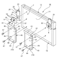
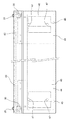
この実施例1は、図1に示すように、この発明を流し台の幕板Mの取り付けに適用した場合を示しており、流し台のキャビネット前面側のベースユニット部1(図11参照)に形成された幕板取付開口部2に幕板Mを嵌合して取り付けるように構成されている。
As shown in FIG. 1, the first embodiment shows a case where the present invention is applied to the mounting of a curtain plate M of a sink, and is formed in a base unit 1 (see FIG. 11) on the front side of the cabinet of the sink. The curtain plate M is fitted and attached to the curtain
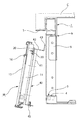
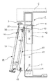
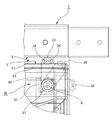
図2に示すように、上記幕板Mの本体11の下辺部10には、上記幕板取付開口部2の下辺部3に開設された止着孔4,4(図11参照)に嵌合係止可能な凸部を構成するなべ小ねじ45,45(図11参照)が着脱自在に螺着されており、また、幕板Mの裏面側には、弾性を有する 固定ピース20を、固定ピース受具30を介して回動可能に取り付け、該固定ピース20は、幕板Mを幕体取付開口部2に止着したときに、幕板取付開口部2の上辺部5と幕板Mの上辺部12との間に形成される空隙部S間に移動させられて、その自由端部21が幕板取付開口部2の上辺部5に弾接し、幕板Mをガタツキが発生しない方向に押圧するように構成されている。
As shown in FIG. 2, the
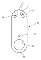
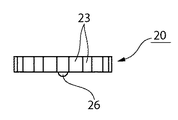
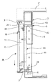
固定ピース20は、図3及び図8乃至図9に示すように、ABS樹脂で縦長で弾性を有して形成されており、自由端部21側及び固定端部22側を円く形成すると共に、上記自由端部側21には凹凸23が連続して形成され、該凹凸23の下方には、2つの係止溝孔24が開設され、さらに、上記固定端部側22には貫通穴25が開設され、さらに、該貫通穴25の上部には、半球状のクリック用突起26が突設されている。
As shown in FIGS. 3 and 8 to 9, the fixed
このように、固定ピース20を弾性を有するABS樹脂で形成し、かつ、上記自由端部21に連続する凹凸23を円く形成することで、固定ピース20の幕板取付開口部2の上辺部5への弾接密着度を増加させることができ、より強い押圧力を得ることができ、幕板Mのガタツキをより確実に防止することができる。
In this way, the fixed
また、この実施例1では、固定ピース20の自由端部21側に、操作具(図示せず)の先端が挿入可能な係止溝孔24を形成したので、幕板Mを取り付けた後、先端が細く錐状の工具を係止溝孔24に挿通し、固定ピース20を垂直方向へと回動させ、或は、取り外す時に固定ピース20を水平方向に、小さな力で容易に回動させることができる。
Further, in the first embodiment, since the locking
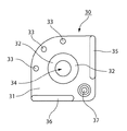
一方、上記固定ピース受具30は、図3乃至図7に示すように、正面形状が略1/4円板形状に形成された本体31と、該本体31に開設され上記固定ピース20に形成された貫通穴25と嵌合係止可能なリング状の突起32が形成されており、また、該リング状の突起32の外周側に沿って、0度、45度、90度の位置に浅い3つのクリック溝33,33,33が凹設されている。尚、図中符号34は、リング状の突起33の中心部に開設されたビス孔である。
Meanwhile, as shown in FIGS. 3 to 7, the fixed
このように、この実施例1にあっては、固定ピース受具30を構成したので、段階的な角度、即ち、水平状態、45度の状態、垂直状態で固定ピース20を係止することができると共に、固定ピース20自体の弾性力による押圧力が作用しなくなるのを、当該クリック用突起26とクリック溝33との係合力で防止することもできる。
Thus, in the first embodiment, since the fixed
また、固定ピース受具30には、固定ピース20を略垂直状態及び水平状態に保持するためのストッパ35,36が突設されており、固定ピース20を垂直位置又は水平位置以上に回転しないように規制することができ、しかも、垂直状態に保持したときには、上記クリック係止状態と相俟って、上記ストッパ35によって固定ピース20が水平位置へと回動するのを規制することができるので、より確実な押圧状態を保持することができる。
Further, the fixed
さらに、上記固定ピース受具30には、幕板Mの裏面側に開設された位置決め孔7に嵌合係止可能な位置決め突起37が突設されており、幕板Mの位置決め孔7に当該位置決め突起37を嵌合係止し、上記ビス孔34にビス8を螺装してこれを緊締することで、当該固定ピース受具30の位置決めを行なうことができ、また、当該固定ピース受具30を1本のビス8で幕板Mに固定するときにも、該固定ピース受具30の回転を防止し、簡単に取り付けることができる。尚、固定ピース20の貫通穴25と固定ピース受具30のリング状の突起32は、固定ピース側に突起を、固定ピース受具側に貫通穴を形成して構成しても同様の効果が得られる。
Further, the fixed
このようにして幕板Mの裏面上部両側に固定ピース20を、固定ピース受具30を介して固定した後に、図11に示すように、幕板固定具40,40が取り付けられる。
Thus, after fixing the fixed
この幕板固定具40は、側面形状が略コ字状に形成された本体部41と、この本体部41の上部に形成された棚部42と、この棚部42から上方に延設された鍔部43と、上記本体部41の下部に突設されたねじ孔44,44と、該ねじ孔44の一方に螺装されるなべ小ねじ45と、から構成されており、このねじ孔44に螺着されたなべ小ねじ45が、本発明の凸部を構成している。また、この幕板固定具40の幕板Mの裏面への取り付けは、本体部41の上下に開設された固定孔46,46にビス47を螺装して固定する。この固定孔46,46は、水平方向に長く形成され、幕板固定具40の水平方向に移動させることで、上記鍔部43と幕板取付開口部2の上辺部5に形成された係止溝6(図15参照)との相対的位置を調整することができるように構成されている。
The curtain
このように、この実施例1では、前記本体部41の下部にねじ孔44,44を開設し、このねじ孔44,44になべ小ねじ45を着脱自在に螺着して凸部を形成したので、凸部の大きさや突出量を、幕板取付開口部2に形成された止着孔4,4の大きさや深さに対応させて容易に交換し調整することができる。
Thus, in this Example 1, the screw holes 44 and 44 were opened in the lower part of the said main-
このようにして組み立てられた幕板Mを、図12乃至図14に示す。 The curtain plate M assembled in this way is shown in FIGS.
次に、上記のようにして組み立てられた幕板Mを、流し台のキャビネット前面側のベースユニット部1に形成された幕板取付開口部2に取り付ける手順を、図15乃至図20に基いて説明する。尚、図15乃至図20では、実施例1で説明した幕板Mとは異なり、幕板Mの表面側に形成された枠部16に化粧材15を嵌装する場合を例にとり説明するが、この発明にあってはこれに限定されるものではなく、公知の各種幕板、例えば、本体11の表面にコート紙を貼着したものにも適用することができる他、他の板材の取り付けにも適用することができる。また、図中符号Cは天板である。
Next, a procedure for attaching the curtain plate M assembled as described above to the curtain
先ず、幕板Mに取り付けられた固定ピース20,20を固定ピース受具30のストッパ36,36に衝合させた状態にセットした後、図15に示すように、幕板固定具40の鍔部43を、ベースユニット部1の幕板取付開口部2の内側部にビス止め固定された平面形状が略L字状の取付金具9,9の奥行側上縁部と幕板取付開口部2の内側上部フレームとの間に形成された係止溝6に、図16に示すように差し込み、この後、幕板Mの下辺部10を上記幕板取付開口部2内に挿入し、幕板Mを垂直状態にセットする。
First, after the fixed
この状態から幕板Mを下方向にスライドさせ、上記幕板取付開口部2の下辺部3に開設された止着孔4,4になべ小ねじ45,45を落とし込み、嵌合係止させる。
From this state, the curtain plate M is slid downward, and the pan head screws 45, 45 are dropped into the fastening holes 4 and 4 formed in the
すると、幕板取付開口部2の上辺部5と幕板Mの上辺部12との間に、図19に示すような空隙部Sが形成されるので、次に、固定ピース20の自由端部21側に開設された係止溝孔24に、操作具(図示せず)の先端を挿入し、固定ピース20を垂直方向へと回動させることで、その自由端部21の凹凸23が幕板取付開口部2の上辺部5に弾接し、幕板Mを下方向に押圧するので、取り付け後における板体のガタツキを確実に防止することができる。勿論、取り外す時に固定ピース20を水平方向に、小さな力で容易に回動させることができる。このように、幕板等の板体の取り付けや交換作業も上記手順だけで非常に簡単に行なうことができる。
Then, a gap S as shown in FIG. 19 is formed between the
M 幕板
1 ベースユニット部
2 幕板取付開口部
3 幕板取付開口部の下辺部
4 止着孔
5 幕板取付開口部の上辺部
6 係止溝
7 位置決め孔
8 ビス
10 幕板の下辺部
11 幕板本体
12 幕板の上辺部
20 固定ピース
21 自由端部
23 凹凸
24 係止溝孔
25 貫通穴
26 クリック用突起
30 固定ピース受具
31 本体
32 突起
33 クリック溝
34 ビス穴
35,36 ストッパ
37 位置決め突起
40 幕板固定具
41 本体部
42 棚部
43 鍔部
44 ねじ孔
45 なべ小ねじ(凸部)
46 固定孔
47 ビス
46
Claims (19)
Priority Applications (1)
| Application Number | Priority Date | Filing Date | Title |
|---|---|---|---|
| JP2004228538A JP4635271B2 (en) | 2004-08-04 | 2004-08-04 | Plate body mounting structure and fixed piece and fixed piece receiver used therefor |
Applications Claiming Priority (1)
| Application Number | Priority Date | Filing Date | Title |
|---|---|---|---|
| JP2004228538A JP4635271B2 (en) | 2004-08-04 | 2004-08-04 | Plate body mounting structure and fixed piece and fixed piece receiver used therefor |
Publications (2)
| Publication Number | Publication Date |
|---|---|
| JP2006043136A JP2006043136A (en) | 2006-02-16 |
| JP4635271B2 true JP4635271B2 (en) | 2011-02-23 |
Family
ID=36022343
Family Applications (1)
| Application Number | Title | Priority Date | Filing Date |
|---|---|---|---|
| JP2004228538A Expired - Fee Related JP4635271B2 (en) | 2004-08-04 | 2004-08-04 | Plate body mounting structure and fixed piece and fixed piece receiver used therefor |
Country Status (1)
| Country | Link |
|---|---|
| JP (1) | JP4635271B2 (en) |
Family Cites Families (3)
| Publication number | Priority date | Publication date | Assignee | Title |
|---|---|---|---|---|
| JPS562009Y2 (en) * | 1977-04-08 | 1981-01-17 | ||
| JPS63106410A (en) * | 1986-10-22 | 1988-05-11 | 株式会社ムラコシ精工 | Tabular body fixture |
| JP4201480B2 (en) * | 2000-12-21 | 2008-12-24 | コクヨ株式会社 | Wall material attachment and wall material attachment structure using the wall material attachment |
-
2004
- 2004-08-04 JP JP2004228538A patent/JP4635271B2/en not_active Expired - Fee Related
Also Published As
| Publication number | Publication date |
|---|---|
| JP2006043136A (en) | 2006-02-16 |
Similar Documents
| Publication | Publication Date | Title |
|---|---|---|
| CN101680664B (en) | Fastening device for fastening objects to a base surface | |
| KR101164025B1 (en) | Supporter for furniture | |
| KR20100008016U (en) | Installation structure of leg for sink | |
| JP4635271B2 (en) | Plate body mounting structure and fixed piece and fixed piece receiver used therefor | |
| US9062697B2 (en) | Hidden fastener | |
| KR101162580B1 (en) | Leg of sink | |
| JP2000055017A (en) | Attaching device for equipment supporting arm to desk top | |
| JPH10215076A (en) | Equipment housing wall hanging device | |
| JP2005040449A (en) | Wall surface attachment structure | |
| JP3171513U (en) | Wall-mounted device for thin display | |
| JP2018178594A (en) | Handrail bracket | |
| JP6761360B2 (en) | Shower hook mounting aid | |
| JPH047828Y2 (en) | ||
| CN217816294U (en) | Rotary fixing device and equipment assembly | |
| CN217379102U (en) | Counter basin mounting structure and wash stand | |
| JP2006149898A (en) | Member fixing structure | |
| JP2005054960A (en) | Decorative panel fixing structure | |
| CN210484269U (en) | A lock and quick disassembly bracket | |
| JP2994551B2 (en) | Blind mounting bracket | |
| JP2019100100A (en) | Pipe holding band attachment | |
| KR20100089420A (en) | Leg of sink | |
| JP3119763U (en) | Display shelf equipment | |
| JPH11315568A (en) | Holding construction for shower head | |
| JP4433751B2 (en) | Article fixture | |
| JP2008163963A (en) | Leg portion mounting structure and table using the same |
Legal Events
| Date | Code | Title | Description |
|---|---|---|---|
| A621 | Written request for application examination |
Free format text: JAPANESE INTERMEDIATE CODE: A621 Effective date: 20070726 |
|
| A977 | Report on retrieval |
Free format text: JAPANESE INTERMEDIATE CODE: A971007 Effective date: 20090410 |
|
| A131 | Notification of reasons for refusal |
Free format text: JAPANESE INTERMEDIATE CODE: A131 Effective date: 20100517 |
|
| A521 | Request for written amendment filed |
Free format text: JAPANESE INTERMEDIATE CODE: A523 Effective date: 20100607 |
|
| TRDD | Decision of grant or rejection written | ||
| A01 | Written decision to grant a patent or to grant a registration (utility model) |
Free format text: JAPANESE INTERMEDIATE CODE: A01 Effective date: 20100907 |
|
| A01 | Written decision to grant a patent or to grant a registration (utility model) |
Free format text: JAPANESE INTERMEDIATE CODE: A01 |
|
| A61 | First payment of annual fees (during grant procedure) |
Free format text: JAPANESE INTERMEDIATE CODE: A61 Effective date: 20100929 |
|
| A61 | First payment of annual fees (during grant procedure) |
Free format text: JAPANESE INTERMEDIATE CODE: A61 Effective date: 20101105 |
|
| FPAY | Renewal fee payment (event date is renewal date of database) |
Free format text: PAYMENT UNTIL: 20131203 Year of fee payment: 3 |
|
| R150 | Certificate of patent or registration of utility model |
Ref document number: 4635271 Country of ref document: JP Free format text: JAPANESE INTERMEDIATE CODE: R150 Free format text: JAPANESE INTERMEDIATE CODE: R150 |
|
| FPAY | Renewal fee payment (event date is renewal date of database) |
Free format text: PAYMENT UNTIL: 20131203 Year of fee payment: 3 |
|
| FPAY | Renewal fee payment (event date is renewal date of database) |
Free format text: PAYMENT UNTIL: 20131203 Year of fee payment: 3 |
|
| R250 | Receipt of annual fees |
Free format text: JAPANESE INTERMEDIATE CODE: R250 |
|
| S111 | Request for change of ownership or part of ownership |
Free format text: JAPANESE INTERMEDIATE CODE: R313111 |
|
| R350 | Written notification of registration of transfer |
Free format text: JAPANESE INTERMEDIATE CODE: R350 |
|
| S111 | Request for change of ownership or part of ownership |
Free format text: JAPANESE INTERMEDIATE CODE: R313111 |
|
| R360 | Written notification for declining of transfer of rights |
Free format text: JAPANESE INTERMEDIATE CODE: R360 |
|
| R360 | Written notification for declining of transfer of rights |
Free format text: JAPANESE INTERMEDIATE CODE: R360 |
|
| R371 | Transfer withdrawn |
Free format text: JAPANESE INTERMEDIATE CODE: R371 |
|
| S111 | Request for change of ownership or part of ownership |
Free format text: JAPANESE INTERMEDIATE CODE: R313111 |
|
| R350 | Written notification of registration of transfer |
Free format text: JAPANESE INTERMEDIATE CODE: R350 |
|
| LAPS | Cancellation because of no payment of annual fees |