JP4635261B2 - Communication system and name server device - Google Patents
Communication system and name server device Download PDFInfo
- Publication number
- JP4635261B2 JP4635261B2 JP2006077826A JP2006077826A JP4635261B2 JP 4635261 B2 JP4635261 B2 JP 4635261B2 JP 2006077826 A JP2006077826 A JP 2006077826A JP 2006077826 A JP2006077826 A JP 2006077826A JP 4635261 B2 JP4635261 B2 JP 4635261B2
- Authority
- JP
- Japan
- Prior art keywords
- name
- cluster
- server device
- network
- devices
- Prior art date
- Legal status (The legal status is an assumption and is not a legal conclusion. Google has not performed a legal analysis and makes no representation as to the accuracy of the status listed.)
- Expired - Fee Related
Links
Images


Landscapes
- Data Exchanges In Wide-Area Networks (AREA)
- Small-Scale Networks (AREA)
Description
本発明は通信システムと、通信システム上で用いられるネームサーバ装置に関し、特にそのネーミング方法に係るものである。 The present invention relates to a communication system and a name server device used on the communication system, and particularly relates to a naming method thereof.
RF-IDやセンサーによる実空間情報がネットで得られるようになったり、ネットワーク接続機能を持つ家電製品がネットワークを経由した制御を受け付けるようになるなど、実空間とネットワークの融合を図ったユビキタス通信環境の整備が急速に進んでいる。
一方、通信ネットワークは有線・無線共に高速・大容量化が急速に進み、また通信時間や通信料によらない定額課金サービスが導入されてきた。これらの組み合わせにより、ユーザがどこにいても気軽に、ネットワークを経由して自宅やオフィスのデバイスを遠隔操作したり、必要な情報を取り出すことができるようになってきている。
Ubiquitous communication that integrates real space and network, such as real-space information from RF-IDs and sensors can be obtained on the Internet, and home appliances with network connection functions can receive control via the network. Improvement of environment is progressing rapidly.
On the other hand, high-speed and large-capacity wired and wireless networks are rapidly increasing in communication networks, and flat-rate billing services that do not depend on communication time or communication charges have been introduced. With these combinations, it has become possible to remotely operate a home or office device or retrieve necessary information via a network, regardless of where the user is.
このような環境ではユーザの利便性が高まる反面、システムの複雑さからユーザに高度な知識を要求したり、設定のミスやシステムの不具合などから第三者によって自分のデバイスや情報への予期せぬアクセスを許してしまう可能性が高くなるなど、危険性も同時に発生し得る。
そのため、設定が容易もしくは不要で、セキュリティ問題が発生しないように
設計されたシステムの実現が望まれる。
In such an environment, the convenience of the user is increased, but the user is required to have advanced knowledge due to the complexity of the system. Danger can also occur at the same time, such as increasing the possibility of allowing unauthorized access.
Therefore, it is desired to realize a system that is easy or unnecessary to set and designed so as not to cause a security problem.
これに対応する方法として、ネットワークアドレスに2つのレイヤを用意し、1つはグローバルなアドレス空間、もう1つはプライベートなアドレス空間とする。これによれば、相互のアドレス空間はルータを介してのみ変換できるから、プライベートなアドレス空間にあるデバイスには他者がアクセスできない利点がある。 As a corresponding method, two layers are prepared for the network address, one is a global address space, and the other is a private address space. According to this, since the mutual address space can be converted only through the router, there is an advantage that a device in the private address space cannot be accessed by others.
このように2つのレイヤのアドレス空間を提案する従来技術として、非特許文献1がある。該文献に開示されるIST-MAGNETプロジェクトでは、PNレイヤとIPレイヤとの2つのレイヤにおいて、PNアドレス空間とグローバルIPアドレス空間とを用意することが提案されている。
そして、あるデバイスはPNアドレスのみを有し、あるデバイスはPNアドレスと共にIPアドレスを有することで、IPレイヤにおいて外部からの接続も可能になっている。
As a conventional technique for proposing two-layer address space in this way, there is Non-Patent
A certain device has only a PN address, and a certain device has an IP address together with the PN address, so that connection from the outside is also possible in the IP layer.
非常に多くのデバイスがネットワークに接続されるようになると、自分の利用したいサービスや接続したいデバイスを発見・特定する手段が重要となる。例えば、今夜放送されるテレビ番組を録画しようとするとき、ユーザは自宅のビデオデッキに対して予約操作を行う必要がある。このとき、ビデオデッキ自体はネットワークに接続されていたとしても、それがIPアドレスのような数字列や記号列で表されているのみであれば、ユーザがネットワーク上からビデオデッキを発見して操作を行うことは難しい。 When a large number of devices are connected to the network, the means for discovering and specifying the service that the user wants to use and the device that the user wants to connect becomes important. For example, when recording a television program to be broadcast tonight, the user needs to perform a reservation operation on the home video deck. At this time, even if the video deck itself is connected to the network, if it is only represented by a numeric string or symbol string such as an IP address, the user can find and operate the video deck from the network. Is difficult to do.
この問題を解決するためには2つの方向性が考えられる。ひとつは、各デバイスにアドレスとは別にユーザがわかりやすい名前をつけることである。とはいえ、実際の通信時にはアドレスを頼りにパケット転送が行われるので、どこかでそのデバイスの名前とアドレスの対応付け(binding)のリストを管理し、適宜変換を行うことでユーザがアドレス列を暗記する必要性を回避することができる。この仕組みをネーミング(naming)と呼んでいる。 There are two ways to solve this problem. One is to give each device a name that is easy for the user to understand apart from the address. Nonetheless, since packet transfer is performed depending on the address during actual communication, the user manages the address list by managing the device name / address binding list somewhere and performing appropriate conversions. The need to memorize can be avoided. This mechanism is called naming.
上記非特許文献1では2つのレイヤのアドレス空間を用いた構成は開示しているが、ネーミング方法については考えられていない。また、非特許文献2ではネーミング方法について提案されているが、PNレイヤのような2つのレイヤとする技術は実現できていない。
Non-Patent
もうひとつの解決法としては、各デバイスが「できること」(サービス)を事前に特定のサーバに登録しておく方法である。ユーザはサーバにしたいこと、例えば「テレビ番組の録画をしたい」と要求を出すと、サーバはリクエストに合致するサービスを提供しているデバイスを検索しその情報を返答することで、ユーザは適切なデバイスにアクセスすることができる。この仕組みはサービス発見(Service Discovery)と呼ばれる。 As another solution, each device can register “what can be done” (service) in a specific server in advance. When the user makes a request to the server, for example, “I want to record a TV program”, the server searches for a device that provides a service that matches the request and returns the information, so that the user Can access the device. This mechanism is called service discovery.
一般に、サービス発見技術はネーミング技術に比べて複雑性が高くなるため、スケーラビリティを確保するのが難しいと言われる。
この2種の技術は排他的なものではなく、組み合わせて使うことでいっそうユーザの利便性を改善できる。例えば、過去の提案技術の中ではIntentional Naming System (INS)(非特許文献3参照)がこの双方の特徴を有している。
In general, it is said that it is difficult to ensure scalability because service discovery technology is more complex than naming technology.
These two technologies are not exclusive and can be used in combination to further improve user convenience. For example, Intentional Naming System (INS) (see Non-Patent Document 3) has features of both of the past proposed technologies.
INSでは、各デバイスが名前要素としてそのデバイスの位置、サービスの種類、アクセス特性などを有し、それらが木構造を構成することにより、ユーザが近隣に存在する欲しいサービスを容易に発見できるという特性を持つ。しかし、この名前空間の伝播・共有をホップ・バイ・ホップで行っているため、インターネットレベルでのスケーラビリティを確保することは難しい。 In INS, each device has the device location, service type, access characteristics, etc. as name elements, and by configuring the tree structure, the user can easily find the service he wants to exist in the neighborhood have. However, since this namespace is propagated and shared on a hop-by-hop basis, it is difficult to ensure scalability at the Internet level.
現在のインターネットにおいては、ネーミング方式としてDomain Name System (DNS)(非特許文献4参照)がデファクトスタンダードとして利用されている。
DNSは階層的な名前空間を有しており、名前はデバイス名とドメイン(組織)名の組み合わせで構成される。例えば、www.nict.go.jpという名前は、はじめの”www”がデバイス名、残りの”nict.go.jp”の部分がドメイン名を示す。このドメイン名の部分が階層化構造を有し(前記の例では、jp→go→nict)、各組織が有するネームサーバは同様の階層構造を有するように構成される。これにより、各組織内で独立してデバイス名を管理でき、ドメイン数やデバイス数が増えても階層構成中に分散収容することでインターネットサイズでのスケーラビリティを獲得している。
In the current Internet, Domain Name System (DNS) (see Non-Patent Document 4) is used as a de facto standard as a naming method.
The DNS has a hierarchical name space, and the name is composed of a combination of a device name and a domain (organization) name. For example, in the name www.nict.go.jp, the first “www” indicates the device name, and the remaining “nict.go.jp” indicates the domain name. The domain name portion has a hierarchical structure (in the above example, jp → go → nict), and the name servers of each organization are configured to have a similar hierarchical structure. As a result, device names can be managed independently within each organization, and even when the number of domains and the number of devices increase, scalability in the Internet size is obtained by distributing and accommodating them in the hierarchical structure.
DNSを引き続き本発明が対象とする次世代ネットワークでも利用していくことが好ましいと考えられるが、そのままでは次世代ネットワークに求められる機能のいくつかが実現できない。
まず、次世代ネットワークではユーザが動くことを前提としており、特にPAN上に存在するデバイスは移動に応じ、頻繁にRadio Access Network (RAN、 例えばEthernet(登録商標)、 無線LAN 802.11g、 W-CDMA(登録商標)などのアクセス方式)を変更しながら、インターネット(もしくはIPベースのバックボーンネットワーク)上の接続点を変更していく。このとき、新しい接続点が同一のドメインに所属するとは限らない。DNSにおいては、デバイスの名前は接続点に依存するため、本質的にデバイスの移動性に追従しているとは言えない。
Although it is considered preferable to continue to use DNS in the next-generation network targeted by the present invention, some functions required for the next-generation network cannot be realized as they are.
First, in the next generation network, it is assumed that the user moves. Especially, devices that exist on the PAN are frequently used as radio access networks (RAN, eg Ethernet (registered trademark), wireless LAN 802.11g, W-CDMA). The access point on the Internet (or IP-based backbone network) is changed while changing the access method (registered trademark). At this time, the new connection point does not necessarily belong to the same domain. In DNS, since the name of a device depends on the connection point, it cannot be said that it essentially follows the mobility of the device.
また、DNSを次世代ネットワークに適用する問題として、基本的に全てのデバイスの情報が公開されてしまうことがある。あらゆるデバイスがネットワークに接続されたとき、ユーザにとっては簡単な名前で各デバイスにアクセスできることがDNSの利点である。しかし、DNSに登録された名称は他のユーザからも参照可能であるので、一般名称や想像の容易な名称をデバイスに付けた場合、不必要に他者からのアクセスを誘引することになりかねない。適切にアクセス制御の設定をしていれば問題とはならないはずではあるが、個人的に使用したいデバイスについては他者に情報を開示しないほうが管理上好ましい。 Further, as a problem of applying DNS to the next generation network, information on all devices may be basically disclosed. When every device is connected to the network, it is an advantage of DNS that the user can access each device with a simple name. However, since the name registered in DNS can be referred to by other users, if a general name or a name that is easy to imagine is given to the device, it may unnecessarily attract access from others. Absent. Although it should not be a problem if the access control is set appropriately, it is preferable in terms of management that the information that is desired for personal use is not disclosed to others.
関連する従来技術として、特許文献5はローカルエリアネットワーク上の装置を探索するシステム及び方法を開示している。
該システムにおいて、ネットワーク上の装置のIPアドレスをグループ名に関連付けるアドレスサーバーと、ネットワークの第1サブネットに配置された発見可能な装置であって、IPアドレスを有してそれがグループ名に関連付けされている発見可能な装置と、ネットワークの第2サブネットに配置され、ネットワーク上の既知のサブネット及び既知の装置のリストを形成し、グループ名に関連したIPアドレスのリストについてネームサーバ ーに問合せし、発見可能な装置のIPサブネット情報についてグループ名に関連した発見可能な装置の各戻りアドレスにコンタクトし、発見可能な装置のサブネットを決定し、そして発見可能な装置及びそのサブネットをリストに追加する発見装置を含むことが開示されている。
As related prior art,
In the system, an address server for associating an IP address of a device on the network with a group name, and a discoverable device located in the first subnet of the network having an IP address associated with the group name. A list of known discoverable devices and a second subnet of the network, forming a list of known subnets and known devices on the network, querying a name server for a list of IP addresses associated with group names, Discovery that contacts each discoverable device's return address associated with the group name for the IP subnet information of the discoverable device, determines the subnet of the discoverable device, and adds the discoverable device and its subnet to the list It is disclosed to include an apparatus.
本発明は、上記従来技術の有する問題点に鑑みて創出されたものであり、デバイスの移動性を確保しながら、アドレスを不必要に他者に公開しないネームネーミング方法を実現する通信システムとネームサーバ装置を提供することを目的とする。 The present invention was created in view of the above-described problems of the prior art, and provides a communication system and a name that realize a name naming method that ensures the mobility of a device and does not unnecessarily disclose addresses to others. An object is to provide a server device.
本発明は、上記の課題を解決するために、次のような通信システムを提供する。
請求項1に記載の通信システムは、デバイスに対して、通信ネットワーク上の第1の領域において使用され、デバイスとネットワークアドレスとの対応付けを行う第1のネームシステムレイヤ上のネームと、より限定的な第2の領域において使用される第2のネームシステムレイヤ上のネームとをそれぞれ付与し、第1及び第2の2つのネームシステムレイヤを用いる。
In order to solve the above-described problems, the present invention provides the following communication system.
The communication system according to
該通信システムにおいて、両方のネームシステムレイヤにおいて機能するネームサーバ装置を備えて、該ネームサーバ装置が、第2のネームシステムレイヤでは、場所毎にデバイスの集合として定義されるクラスタ毎に設けられ、クラスタ内の単数又は複数のデバイスから少なくともネットワークアドレスを含むデバイス登録情報を取得し、該クラスタにおけるデバイスとネットワークアドレスとの対応付けリストを記憶すると共に、第2のネームシステムレイヤ内にある他のクラスタのネームサーバ装置と該対応付けリストを交換するリンクを有して、第2の領域に属するユーザのみに対して該対応付けリストによるデバイスとネットワークアドレスとの変換機能を提供する。 The communication system includes a name server device that functions in both name system layers, and the name server device is provided for each cluster defined as a set of devices for each location in the second name system layer, Acquire device registration information including at least a network address from one or more devices in the cluster, store a correspondence list of devices and network addresses in the cluster, and other clusters in the second name system layer A name server device and a link for exchanging the association list are provided, and a device / network address conversion function based on the association list is provided only to users belonging to the second area.
請求項2に記載の通信システムは、ネームサーバ装置が、他のクラスタのネームサーバ装置と対応付けリストを交換する際に、通信システムに各クラスタのルータとなるエッジサーバ装置を備え、各クラスタにおいて、該エッジサーバ装置が該ネームサーバ装置が取得したデバイス登録情報に基づいて、該エッジサーバ装置に付与された第1の領域におけるネットワークアドレスを該デバイスに通知することを特徴とする。
The communication system according to
請求項3に記載の通信システムは、エッジサーバ装置間をVPN(Virtual Private Network:仮想私設網)を用いて接続することを特徴とするものである。
The communication system according to
請求項4に記載の通信システムは、上記の通信システムにおいて、各クラスタのエッジサーバ装置に付与された第1の領域におけるネットワークアドレスを前記デバイス又は、前記ネームサーバ装置、前記エッジサーバ装置の少なくともいずれかから取得し、他のクラスタの少なくともエッジサーバ装置に通知することにより、エッジサーバ装置間でのネットワークアドレスの交換を可能にするエージェントサーバ装置を備えたことを特徴とする。
The communication system according to
請求項5に記載の通信システムは、第2のネームシステムレイヤにおける各デバイスのネームの一部に、該クラスタのクラスタ名を含む構成において、各ネームサーバ装置が、他のクラスタのネームサーバ装置に向けて該クラスタ名を広告することを特徴とする。
The communication system according to
本発明は、次のようなネームサーバ装置を提供することができる。
すなわち、請求項6に記載の発明はは、デバイスに対して、通信ネットワーク上の第1の領域において使用され、デバイスとネットワークアドレスとの対応付けを行う第1のネームシステムレイヤ上のネームと、より限定的な第2の領域において使用される第2のネームシステムレイヤ上のネームとをそれぞれ付与し、第1及び第2の2つのネームシステムレイヤを用いる通信システムにおいて用いるネームサーバ装置である。
The present invention can provide the following name server device.
That is, the invention according to
該ネームサーバ装置は、両方のネームシステムレイヤにおいて機能し、第2のネームシステムレイヤでは、場所毎にデバイスの集合として定義されるクラスタ毎に設けられ、クラスタ内の単数又は複数のデバイスから少なくともネットワークアドレスを含むデバイス登録情報を取得し、該クラスタにおけるデバイスとネットワークアドレスとの対応付けリストを記憶すると共に、第2のネームシステムレイヤ内にある他のクラスタのネームサーバ装置と該対応付けリストを交換するリンクを有して、第2の領域に属するユーザのみに対して該対応付けリストによるデバイスとネットワークアドレスとの変換機能を提供する。 The name server apparatus functions in both name system layers. In the second name system layer, the name server apparatus is provided for each cluster defined as a set of devices for each location, and at least a network from one or more devices in the cluster. Acquires device registration information including an address, stores a correspondence list of devices and network addresses in the cluster, and exchanges the correspondence list with name server devices of other clusters in the second name system layer And providing a function for converting a device and a network address according to the association list only to users belonging to the second area.
請求項7に記載の発明は、上記の第2のネームシステムレイヤにおける各デバイスのネームの一部に、該クラスタのクラスタ名を含む構成において、各ネームサーバ装置が、他のクラスタのネームサーバ装置に向けて該クラスタ名を広告することを特徴とする。 According to a seventh aspect of the present invention, in the configuration in which a part of the name of each device in the second name system layer includes the cluster name of the cluster, each name server device is a name server device of another cluster The cluster name is advertised toward.
本発明は、上記構成を備えることにより次のような効果を奏する。
すなわち、請求項1に記載の発明によれば、第1の領域と第2の領域における2つのネームシステムレイヤを用いることで第2の領域に属するユーザ以外から、第2の領域にあるデバイスへのアクセスを防ぐことができ、セキュリティの向上に寄与する。
同時に、第2の領域に属するユーザには、異なる場所のクラスタでも、自由にデバイスへのアクセスが可能であり、移動時の利便性が向上する。
The present invention has the following effects by providing the above configuration.
In other words, according to the first aspect of the present invention, by using two name system layers in the first area and the second area, a user in the second area can be transferred from a user who belongs to the second area. Can be prevented and contributes to security improvement.
At the same time, the user belonging to the second area can freely access the device even in a cluster at a different location, and convenience during movement is improved.
請求項2に記載の発明は、エッジサーバ装置を別に備えることにより、ネームサーバ装置が直接通信ネットワークに接続しないので、セキュリティの向上に寄与する。
請求項3に記載の発明は、VPN接続により、信頼性の高いエッジサーバ装置間接続を実現する。
According to the second aspect of the present invention, since the name server device is not directly connected to the communication network by providing the edge server device separately, it contributes to the improvement of security.
The invention according to
請求項4に記載の発明は、エージェントサーバ装置を用いることによりエッジサーバ装置間のネットワークアドレス交換を、エッジサーバ装置から行う必要がない。各エッジサーバ装置を一括して管理することができる。 According to the fourth aspect of the present invention, it is not necessary to perform network address exchange between the edge server devices from the edge server device by using the agent server device. Each edge server device can be managed collectively.
請求項5に記載の発明は、クラスタ名をネームサーバ装置が広告することで、他のクラスタのデバイスへのアクセスを容易に実現することができる。 According to the fifth aspect of the present invention, the name server device advertises the cluster name, so that access to devices in other clusters can be easily realized.
請求項6及び7に記載の発明によれば、上記の通信システムで用いられるネームサーバ装置を提供することができる。
According to invention of
以下、本発明の実施形態を、図面に示す実施例を基に説明する。なお、実施形態は下記に限定されるものではない。
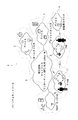
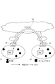
まず、図1を用いて本発明におけるパーソナルネットワーク(PN)と、クラスタ、さらにP−PAN(Private Personal Area Network)の定義について説明する。
通常のPANはブルートゥースや無線LANなど、ユーザの近傍に存在するデバイス群で形成された(無線)リンクレベルのネットワークである。一方、本発明では、デバイスの所有者の情報を考慮し、単一ユーザのデバイス群のみで形成される第2の領域であるPANをP−PAN(1)と呼ぶ。
このP−PAN内は信頼済みとしてデータの送受やアクセスが自由に行える一方、P−PAN外のデバイスとの通信は制限される。
Hereinafter, embodiments of the present invention will be described based on examples shown in the drawings. The embodiment is not limited to the following.
First, the definition of a personal network (PN), a cluster, and a P-PAN (Private Personal Area Network) in the present invention will be described with reference to FIG.
A normal PAN is a (wireless) link level network formed by a group of devices existing in the vicinity of a user, such as Bluetooth or wireless LAN. On the other hand, in the present invention, in consideration of the information of the owner of the device, the PAN that is the second area formed only by the device group of a single user is called P-PAN (1).
While this P-PAN is trusted, data can be sent and received and accessed freely, while communication with devices outside the P-PAN is restricted.
同様に、自宅や会社、車などユーザが長時間滞在する場所においても同様に、単一ユーザの所有するデバイスのみで小規模なネットワークが形成される。
この局所的なデバイスの集合体をクラスタ(2)(3)(4)と呼ぶ。P−PAN(1)と同様にこのクラスタ内はセキュアなものとして自由に通信が行えるが、クラスタ外との通信は制限される。
Similarly, in a place where a user stays for a long time, such as at home, at a company, or in a car, similarly, a small network is formed only by devices owned by a single user.
This local collection of devices is called cluster (2) (3) (4). Similar to P-PAN (1), the inside of this cluster can be freely communicated as being secure, but communication outside the cluster is limited.
P−PANや各クラスタは、インターネットやUMTS(Universal Mobile Telecommunications System)、無線LANやadhoc通信などの第1の領域である相互接続ネットワーク(5)によって接続される。
その際、ユーザの必要に応じて動的に例えばVPN(Virtual Private Network)を用いてセキュアな方式で結ぶことで、ユーザは場所を気にすること無く自分の所有する全てのデバイスやデータにアクセスすることが可能となる。
The P-PAN and each cluster are connected by an interconnection network (5) which is a first area such as the Internet, UMTS (Universal Mobile Telecommunications System), wireless LAN, and adhoc communication.
At that time, users can access all devices and data they own without worrying about the location by dynamically connecting with a secure method using, for example, VPN (Virtual Private Network) according to the user's needs. It becomes possible to do.
ユーザから見たときに、クラスタ(2)(3)(4)に存在するデバイスも手元、すなわちP−PAN内に存在するかのように簡単に扱えるようになる。このP−PANとクラスタから構成される仮想ネットワークをパーソナルネットワーク(PN)(6)と呼ぶ。 When viewed from the user, the devices existing in the clusters (2), (3), and (4) can be easily handled as if they exist at hand, that is, in the P-PAN. A virtual network composed of the P-PAN and the cluster is called a personal network (PN) (6).
次に、本発明の特徴であるネームシステムの構成について説述する。
前述のとおり、DNSサーバに登録したデバイス名はすべてのユーザに対して公開されることになり、セキュリティの観点からすべてのデバイスの名前を登録するのは好ましいとはいえない。
そこで、DNS持つ名前空間を2つのネームシステムレイヤに分け、一方を自分自身のみがアクセス可能な名前空間(第2ネームシステムレイヤ)に、もう一方には他者からアクセスを許すデバイスのみを登録する名前空間(第1ネームシステムレイヤ)として分離する。前者のレイヤをPNレイヤ、後者のレイヤをIPレイヤと呼ぶものとする。図2にその全体図を示す。
Next, the configuration of the name system that is a feature of the present invention will be described.
As described above, the device names registered in the DNS server are made public to all users, and it is not preferable to register the names of all devices from the viewpoint of security.
Therefore, the DNS name space is divided into two name system layers, one of which is accessible only to itself (second name system layer), and the other device is registered only with devices that can be accessed by others. Separate as a name space (first name system layer). The former layer is called a PN layer, and the latter layer is called an IP layer. FIG. 2 shows an overall view thereof.
IPレイヤ(10)とはすなわち、現在のDNSアーキテクチャそのものである。他者からのアクセスを受け入れるデバイスの名前は階層的な名前空間中に記録され、グローバルに有効となる。
一方、PNレイヤ(20)は自分からのみアクセス可能な名前空間を構成する。すなわち、IPレイヤ(10)はグローバルに1つしか存在しないが、PNレイヤ(20)はユーザごとに1つずつ存在する。
That is, the IP layer (10) is the current DNS architecture itself. The names of devices that accept access from others are recorded in a hierarchical name space and are globally valid.
On the other hand, the PN layer (20) constitutes a name space accessible only from itself. That is, there is only one IP layer (10) globally, but there is one PN layer (20) for each user.
PNレイヤ(20)がユーザごとに名前空間を構成するのは、セキュリティ面以外にもメリットがある。それぞれのユーザの名前空間は独立であるので、ユーザごとに同一のデバイス名を使っても問題にならないということである。例えば、“tv“や“pc“、“printer“などの名称は直感的に理解しやすいので多くのユーザが使用することが考えられる。ユーザAとユーザBの名前空間は独立であるので、両ユーザが自分のパソコンに“pc“というデバイス名を付けても問題とならず、それぞれ異なるPCのアドレスをバインドすることができる。 The fact that the PN layer (20) forms a name space for each user has advantages other than security. Since each user's name space is independent, there is no problem even if the same device name is used for each user. For example, names such as “tv”, “pc”, and “printer” are easy to understand intuitively and can be used by many users. Since the name spaces of user A and user B are independent, it does not matter if both users assign a device name “pc” to their personal computers, and different PC addresses can be bound to each other.
ただし、これはPNレイヤ(20)についてであり、IPレイヤ(10)ではFQDN(Fully Qualified Domain Name、ドメイン名も含めた名前)のレベルで独立である必要がある。
つまり、ユーザAとユーザBが同一ドメインに所属し、それぞれ自分のパソコンを他者からのアクセスを受け入れるように公開する場合、それぞれのパソコンに対して重複しない名前をつける必要がある。
However, this is for the PN layer (20), and the IP layer (10) needs to be independent at the level of FQDN (Fully Qualified Domain Name).
That is, when user A and user B belong to the same domain and each of their personal computers is opened to accept access from others, it is necessary to give unique names to the personal computers.
図2において、各クラスタに配置されるPNS(Personal Name Server)が本発明のネームサーバである。クラスタ中の全てのデバイスは、後述するようにサブセットプログラムを備えたデバイス間通信部を備えており、その中で比較的リソースが豊かなデバイス(例えばパソコンや携帯電話端末)を定めてサーバとして機能させる。
その他のデバイス上ではクライアントとして動作させる。特に、このサーバとして動作するデバイスがPNSである。ホームクラスタのPNS(21)は例えば家庭においてあるパソコンであり、家庭内の通信端末、テレビ、エアコン等のさまざまな機器がクライアントとなるデバイスである。
In FIG. 2, PNS (Personal Name Server) arranged in each cluster is the name server of the present invention. All devices in the cluster have an inter-device communication unit with a subset program as will be described later. Among them, devices with relatively rich resources (for example, personal computers and mobile phone terminals) are defined and function as servers. Let
Operate as a client on other devices. In particular, a device that operates as the server is a PNS. The PNS (21) of the home cluster is, for example, a personal computer in the home, and is a device in which various devices such as a home communication terminal, a TV, and an air conditioner are clients.
一方、IPレイヤ(10)において、PNSは機能付加ネームサーバと接続する。機能付加ネームサーバは、DNS本来の機能を有する基本部分と、追加機能を実装した拡張部分の組み合わせによって構成される。拡張部分を使用しなければ既存のDNSサーバと同様の振る舞いができる。
一時にインターネット上のすべてのDNSサーバを機能付加ネームサーバに置き換えることは現実的に不可能であるので、段階的な移行を考えたときにもこの構成は有効である。
On the other hand, in the IP layer (10), the PNS is connected to a function-added name server. The function-added name server is configured by a combination of a basic part having an original DNS function and an extended part in which an additional function is implemented. If the extension part is not used, the same behavior as an existing DNS server can be performed.
Since it is practically impossible to replace all DNS servers on the Internet with function-added name servers at a time, this configuration is also effective when considering phased migration.
この機能付加ネームサーバをNNS(New NamingScheme)サーバという。NNSサーバは、現在のDNSサーバと同様に階層的に配置される。インターネット(11)には多数のNNSサーバが配置されるが、図2においてHNS(Home Name Server)(12)はユーザが通常使うドメインのNNSサーバである。 This function-added name server is called an NNS (New Naming Scheme) server. NNS servers are arranged hierarchically in the same way as current DNS servers. A large number of NNS servers are arranged on the Internet (11). In FIG. 2, an HNS (Home Name Server) (12) is an NNS server in a domain that a user normally uses.
FNS(Foreign Name Server)(13)は、ユーザのP−PANがインターネット(11)へ接続するときに接続しているドメインにあるNNSサーバであり、例えばそのインターネットプロバイダのデバイスの名前情報を管理している。
したがって、ユーザがオフィスクラスタ(14)にいるときにはその会社のドメインのFNS(13)が、ホームクラスタ(15)にいるときには家庭のインターネットプロバイダのFNS(16)が用いられることになる。
An FNS (Foreign Name Server) (13) is an NNS server in a domain connected when a user's P-PAN connects to the Internet (11), and manages name information of the device of the Internet provider, for example. ing.
Therefore, when the user is in the office cluster (14), the FNS (13) of the company domain is used, and when the user is in the home cluster (15), the FNS (16) of the home Internet provider is used.
NNSサーバは、このような本発明の機能を備えたネームサーバ一般を指しており、HNS、FNSはユーザとの関係における区別のために名称を異にして説明しているだけで、構成は同一である。また、前述のPNSのデバイス間通信部の機能は、NNSサーバが有する機能のサブセットである。 The NNS server refers to a general name server having the functions of the present invention, and the HNS and FNS are described with different names for the purpose of distinguishing them in relation to users, and the configuration is the same. It is. Further, the above-described functions of the PNS inter-device communication unit are a subset of the functions of the NNS server.
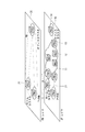
次に、図3には本発明における各サーバ・デバイスの構成を示す構成図を示す。また、図4は、1つのクラスタにおけるPNSとデバイスの関係を示している。図5はPNSとデバイスの間のメッセージフローである。
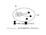
PNS(30)は、P−PAN/クラスタ(31)中でいわゆるマスターノードとして機能する。PNS(30)は、デバイス間通信部(31)から自分のP−PAN/クラスタ中に定期的に広告パケット(advertisement)をブロードキャスト(50)し、他のデバイス(40)に自分の存在を伝える。
この広告パケットには、そのP−PAN/クラスタ固有のID情報としてクラスタ名(cluster_name)を含める。このcluster_nameは手動で設定される(例えば“home“や“office“などのユーザが理解しやすいもの)のが好ましい。
Next, FIG. 3 is a block diagram showing the configuration of each server device in the present invention. FIG. 4 shows the relationship between PNS and devices in one cluster. FIG. 5 is a message flow between the PNS and the device.
The PNS (30) functions as a so-called master node in the P-PAN / cluster (31). The PNS (30) periodically broadcasts (50) an advertisement packet (advertisement) from its inter-device communication unit (31) into its own P-PAN / cluster, and informs the other device (40) of its existence. .
The advertisement packet includes a cluster name (cluster_name) as ID information unique to the P-PAN / cluster. This cluster_name is preferably set manually (for example, a user such as “home” or “office” that is easy to understand).
一方、PNSにならなかったデバイスは、デバイス間通信部(41)のクライアント機能によって自分の情報をPNSに登録する。クライアントは、自分がどのP−PAN/クラスタに存在しているかをPNSがブロードキャストしたcluster_nameから把握する。
電源投入直後など、まだどのPNSにも登録されていない場合や、デバイスが新しいP−PAN/クラスタに移動したことを検出した場合、デバイス間通信部(41)はPNS(30)に対して登録(registration)パケットを送信(51)する。
On the other hand, a device that has not become a PNS registers its information in the PNS by the client function of the inter-device communication unit (41). The client knows in which P-PAN / cluster it is present from the cluster_name broadcast by the PNS.
When it is not registered in any PNS yet, such as immediately after power-on, or when it is detected that the device has moved to a new P-PAN / cluster, the inter-device communication unit (41) registers with the PNS (30). (registration) packet is transmitted (51).
この登録パケットには、少なくともIPアドレス(address)が含まれていなくてはならない。そのほか、デバイスの種類(device_type)や、ユーザがそのデバイスを他者に対して公開したい場合にデバイス公開フラグ(public_flag)、また多数のデバイスがネットワークにつながるので、デバイスの名前は自動付与されるのが利便性の点で好ましいが、ユーザが任意の名前を付与したい場合はデバイス名(device_name)を明示しても良い。 This registration packet must include at least an IP address. In addition, the device type (device_type), device public flag (public_flag) when the user wants to make the device public to others, and many devices are connected to the network, so the device name is automatically assigned Is preferable from the viewpoint of convenience, but if the user wants to assign an arbitrary name, the device name (device_name) may be clearly indicated.
このような手順で、PNS(30)はそのP−PAN/クラスタ中の全てのデバイス(40)について情報を得、デバイスデータベース(32)に格納する。
得た情報のうち、任意の名前が設定されていないデバイスに対しては名前の自動生成(52)を行うこともできる。収集したデバイスの種類の情報とcluster_nameを利用して、device_type[serial_number].cluster_nameの書式での名前の生成をしてもよい。具体的には、“tv01.livingroom“や、“printer03.office“といった名前が生成される。
デバイスの種類と場所の情報を含むので、ユーザにとって理解しやすい名前が得られる。
With such a procedure, the PNS (30) obtains information on all devices (40) in the P-PAN / cluster and stores them in the device database (32).
Among the obtained information, automatic name generation (52) can be performed for a device for which an arbitrary name is not set. Using the collected device type information and cluster_name, a name in the format device_type [serial_number] .cluster_name may be generated. Specifically, names such as “tv01.livingroom” and “printer03.office” are generated.
Includes device type and location information, giving users a name that is easy to understand.
なお、シリアル番号は同種のデバイスがP−PAN/クラスタ内に存在したときに名前が重複するのを回避するためのものであり、名前の重複が無い場合は必須ではない。”tv01”と”tv02”のようにシリアル番号で重複を回避した場合、”tv01”が2台のテレビのうちどちらを指すのかを認識するのは難しい。サービス発見機能やコンテキスト管理技術などと連携してより詳細なデバイス情報を得て、メーカ名やディスプレイの大きさなど、2台間で差異のある部分を名前に組み込むと好適である。 The serial number is for avoiding duplication of names when devices of the same type exist in the P-PAN / cluster, and is not essential when there is no duplication of names. When duplication is avoided by serial numbers such as “tv01” and “tv02”, it is difficult to recognize which of the two TVs “tv01” indicates. It is preferable to obtain more detailed device information in cooperation with a service discovery function, context management technology, etc., and to incorporate a part that differs between the two devices, such as the manufacturer name and display size, into the name.
なお、一度PNSに登録を行ったクライアントは、変更や移動が無い限り低い頻度でPNSに対して周期的に通知(alive signal)(53)を行う。
以上の過程で得られたデバイスの名前とアドレスのbindingリストは、PNSによって一定期間記憶される。この一定期間内にデバイスから周期的に送られてくるべきalive signalを受け取れなかったとき、PNSはそのデバイスが移動したかアクティブではなくなった(例えばバッテリーが切れた)と判断し、リスト(デバイスDB)から抹消する。
Note that a client that has once registered in the PNS periodically sends an alive signal (53) to the PNS at a low frequency as long as there is no change or movement.
The device name and address binding list obtained in the above process is stored by the PNS for a certain period. When the alive signal that should be sent periodically from the device is not received within this fixed period, the PNS determines that the device has moved or is no longer active (for example, the battery has run out), and the list (device DB ).
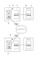
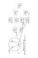
このようにしてPNS(30)に集められたデバイスの情報は、ユーザ自身が利用するためにPNレイヤ中の各PNS間で共有される。図6にこのPNS間の通信を説明する構成図を、図7に情報共有する時のメッセージフローを示す。
PNレイヤ及びPNレイヤが構成する名前空間はフラットな構成をとっているため、各PNSは対等な関係となる。よって、PNレイヤのネーミング方式とは、各PNSが持っているデバイスの情報をどのようにして共有するか、と言い換えることができる。
The device information collected in the PNS (30) in this way is shared among the PNSs in the PN layer for use by the user. FIG. 6 shows a configuration diagram for explaining communication between the PNS, and FIG. 7 shows a message flow when information is shared.
Since the name space formed by the PN layer and the PN layer has a flat configuration, each PNS has an equal relationship. Therefore, the PN layer naming scheme can be paraphrased as how to share device information held by each PNS.
本発明では、各PNSが所有する情報を他のPNSとの間であらかじめ交換しておくproactive方式を採用している。各PNSは、PNS間通信部(33)により他のPNSを探すために定期的にPN全体に広告パケット(hello packet)をブロードキャスト(70)する。この時、この広告パケットには自分のcluster_nameを付加して送信する。 The present invention employs a proactive method in which information owned by each PNS is exchanged in advance with another PNS. Each PNS periodically broadcasts (70) an advertisement packet (hello packet) to the entire PN in order to search for another PNS by the inter-PNS communication unit (33). At this time, this advertisement packet is transmitted with its own cluster_name added.
クラスタ名の広告は、各クラスタとインターネットとの間でルータとして作用するエッジサーバ(60)(61)間でVPN接続(62)を予め確立し、該エッジサーバを介してPNS間で行われる。これによってセキュアな通信が実現する。
なお、本発明の実施には、必ずしもエッジサーバを用いず、PNSが直接にインターネットと接続してクラスタ名の広告を行ってもよい。
する。
The advertisement of the cluster name is performed between the PNS via the edge server by establishing in advance a VPN connection (62) between the edge servers (60) and (61) acting as routers between each cluster and the Internet. This realizes secure communication.
In implementing the present invention, the edge name server is not necessarily used, and the PNS may directly connect to the Internet to advertise the cluster name.
To do.
このブロードキャストを受け取った他のPNSのPNS間通信部(33’)は、受け取ったcluster_nameが既知か未知かを確認する。未知であった場合、そのP−PAN/クラスタのデバイス情報をまだ知らないということであるので、相互にデバイス情報を交換する。
そこで、ブロードキャストを受け取ったPNS(30’)は、送信側PNS(30)に対して応答パケット(acknowledgement)を送信(71)する。このとき、応答パケットに受け取り側のcluster_nameを付加する。
The inter-PNS communication unit (33 ′) of the other PNS that has received this broadcast confirms whether the received cluster_name is known or unknown. If it is unknown, it means that the device information of the P-PAN / cluster is not yet known, so device information is exchanged with each other.
Therefore, the PNS (30 ′) that has received the broadcast transmits (71) a response packet (acknowledgement) to the transmitting side PNS (30). At this time, the cluster_name on the receiving side is added to the response packet.
こうして双方のcluster_nameの交換をした後に、互いのPNSが持つ、自分のP−PAN/クラスタ下に存在するデバイスの情報を交換する。すなわち、cluster_nameと、該クラスタ内のデバイスとアドレスの対応付けリストall_bindingsをPNS(30)が送信(72)すると、その応答及び受け取り側の同内容を返信(73)する。 After exchanging both cluster_names in this way, the information of the devices existing in the P-PAN / cluster of each other's PNS is exchanged. That is, when the PNS (30) transmits (72) the cluster_name and the device-address association list all_bindings in the cluster, the response and the same contents on the receiving side are returned (73).
このような手順を全PNS間で行うことで、各PNSが完全な名前空間情報を有することができる。つまり、各PNSは全てのクエリに対して自力でリゾルブ可能となり、他のPNSなどにクエリを転送する必要は無くなる。
名前空間の交換が終わった後に、あるP−PAN/クラスタに新しいデバイスが接続されるなどデバイス情報が更新された場合、そのP−PAN/クラスタのPNSは情報交換を行った全てのPNSに対して即座にユニキャスト(もしくは可能であればマルチキャスト)でその変更差分を送り、各PNSが常に最新の情報を有するように維持する。
By performing such a procedure between all PNSs, each PNS can have complete name space information. That is, each PNS can resolve itself for all queries, and there is no need to transfer the query to another PNS.
When device information is updated after a namespace exchange is completed, such as when a new device is connected to a P-PAN / cluster, the PNS of that P-PAN / cluster The change difference is sent immediately by unicast (or multicast if possible), and each PNS is always kept up-to-date.
各PNS中では、交換したデバイス情報にcluster_nameとタイマ情報を付加してデバイスDBに記憶される。各PNSは、前述のように定期的にhelloパケットをブロードキャストしているので、このブロードキャストが一定時間(タイマの設定値)中に受信できなかった場合、該当するP−PAN/クラスタに存在する(していた)デバイスの情報は破棄される。 In each PNS, cluster_name and timer information are added to the exchanged device information and stored in the device DB. Since each PNS broadcasts a hello packet periodically as described above, if this broadcast cannot be received within a certain time (set value of the timer), it exists in the corresponding P-PAN / cluster ( Device information) is discarded.
本実施例ではproactive方式を利用しているが、クエリの発生が少ない環境においてはreactive方式の方が通信効率が良くなる可能性もある。この場合のreactive方式とは、helloパケットで相手を知ってもデバイス情報の交換は行なわず、クエリが来たときにそれを他のPNSに転送を行ってリゾルブする方式を指す。上記のような名前の自動生成を行う場合、例えば“tv01.livingroom“というデバイス名に対するクエリが来た場合、このクエリは“livingroom“クラスタに問い合わせるとリゾルブ可能であることが明確であるため、高い通信効率を期待できる。 Although the proactive method is used in this embodiment, the reactive method may improve communication efficiency in an environment where the number of queries is small. In this case, the reactive method refers to a method in which device information is not exchanged even if a partner is known by a hello packet, but when a query comes, it is transferred to another PNS for resolving. When performing automatic generation of the above name, for example, when a query for the device name “tv01.livingroom” comes, it is clear that this query can be resolved by querying the “livingroom” cluster, which is high. Communication efficiency can be expected.
本発明に係るPNレイヤは、IPレイヤの名前空間とは何らの関連も持たないので、上記したPNレイヤにおける対応付けリストの交換はIPレイヤにおける階層とは関連がない一方、ユーザはどのクラスタに移動しても共有されたデバイス情報を利用することができる。
さらに本発明は、IPレイヤにおいてアクセス可能なデバイスについて、P−PANが変化してもそれを追跡して利用可能とする仕組みを備えている。以下にIPレイヤにつき説述する。
Since the PN layer according to the present invention has nothing to do with the name space of the IP layer, the exchange of the association list in the PN layer has no relation to the hierarchy in the IP layer, while the user belongs to which cluster. You can use shared device information even if you move.
Furthermore, the present invention includes a mechanism for tracking and using a device that can be accessed in the IP layer even if the P-PAN changes. The IP layer is described below.
IPレイヤの名前空間は、既存のDNSが構成する名前空間と同じく階層構造を有している。全てのデバイスは特定のドメインに所属することで分散管理を可能としていると共に、名前自身に階層構造を含むので、反復検索(iterative query)によってそのデバイスの所属ドメインのネームサーバまで到達できるという特徴を有する。
現状では、DNSに登録されているインターネット上のデバイスの大半は固定的であり、ほとんど変化しない。ダイヤルアップのユーザなど、割り当てられるIPアドレスが動的に変化するユーザのために、DNSの登録を動的に更新できる仕組み(非特許文献6)も提案・実装されているが、想定している更新の頻度はそれほど高くない。
The name space of the IP layer has a hierarchical structure similar to the name space formed by the existing DNS. All devices belong to a specific domain to enable distributed management, and the name itself includes a hierarchical structure, so that it is possible to reach the name server of the domain to which the device belongs by iterative query. Have.
At present, most of the devices on the Internet registered in the DNS are fixed and hardly change. A mechanism that can dynamically update DNS registration (non-patent document 6) has also been proposed and implemented for users whose assigned IP addresses change dynamically, such as dial-up users. The frequency of updates is not so high.
一方、次世代ネットワークは携帯電話サービスのような高いモビリティを持つものも収容していかなくてはならない。ネットワークへの接続点を変えながら高速移動していく場合、そのデバイスのIPアドレスを頻繁に更新され、ネームサーバにも頻繁な更新を行うことになるだろう。そのような頻繁なbindingの更新にも耐えうるようなネーミング方式が求められる。 On the other hand, next-generation networks must also accommodate high mobility devices such as mobile phone services. When moving at high speed while changing the connection point to the network, the IP address of the device will be updated frequently, and the name server will also be updated frequently. There is a need for a naming scheme that can withstand such frequent binding updates.
NNSのIPレイヤに登録するデバイスは全てのユーザが参照可能となるので、必要最低限のデバイス、すなわち他者からのアクセスを許可するデバイスのみ登録するべきである。そのため、デバイス(40)のデバイス間通信部(41)から送信される「デバイス公開フラグ」をonにセットされたデバイスのみが登録される。 Since all users can refer to devices registered in the NNS IP layer, only the minimum necessary devices, that is, devices that allow access from others should be registered. For this reason, only devices whose “device disclosure flag” transmitted from the inter-device communication unit (41) of the device (40) is set to on are registered.
公開フラグがonのデバイスは、ユーザにより固有の名前を設定されていなくてはならない(例えば“pc01“)。ユーザの、いわゆるホームネットワークのドメイン名(例えば“nict.go.jp“)と合わせて、そのデバイス固有のFQDN(この例の場合は“pc01.nict.go.jp“) が得られる。
つまり、誰かがこの“pc01.nict.go.jp“にアクセスしようとするとき、そのユーザはnict.go.jpドメインのネームサーバに記録されている情報からリゾルブすることになる。
A device whose public flag is on must have a unique name set by the user (for example, “pc01”). Together with the domain name of the user's so-called home network (for example, “nict.go.jp”), a device-specific FQDN (“pc01.nict.go.jp” in this example) is obtained.
In other words, when someone tries to access “pc01.nict.go.jp”, the user resolves from the information recorded in the name server of the nict.go.jp domain.
上述した通り、ユーザのホームネットワークのドメインを管理するNNSがHNSである。図8にIPレイヤのネームサーバと名前空間の構成を示す。
デバイスのIPアドレスが変更になったとき、PNSはHNSに最新のアドレス情報(対応付けリスト)を送信することで、HNSに記録されているbindingを更新するのが原則である。
As described above, the NNS that manages the domain of the user's home network is the HNS. FIG. 8 shows the configuration of the name server and name space of the IP layer.
When the IP address of a device is changed, the PNS basically updates the binding recorded in the HNS by sending the latest address information (association list) to the HNS.
しかし、HNSとPNSがネットワーク的に遠い場合や、P−PANとインターネット間をつなぐ回線の通信速度が遅い場合、頻繁にbinding更新を行うとデータ転送に使うべき帯域までこの更新で占有してしまうことにもなりかねず、工夫が必要となる。 However, if the HNS and PNS are distant from each other in the network, or if the communication speed of the line connecting the P-PAN and the Internet is slow, frequently updating the binding will occupy the band to be used for data transfer. It can also be a thing, and ingenuity is necessary.
そこで、P−PAN/クラスタが接続しているネットワーク(attaching network)のNNSサーバ(上記の通りFNSと呼んでいる)が連携動作する。
本来のPNSとHNS間でbinding更新を行う代わりに、PNSとFNS間でbinding更新を行う。
Therefore, an NNS server (referred to as FNS as described above) of the network (attaching network) to which the P-PAN / cluster is connected operates.
Instead of updating the binding between the original PNS and the HNS, the binding is updated between the PNS and the FNS.
合わせて、HNSとFNS間の連携も必要となる。FNSは、自分のアドレスと、自分が代理でアップデートを受け取っているP−PAN/クラスタ中のデバイス名をHNSに通知する。 In addition, cooperation between HNS and FNS is also required. The FNS notifies the HNS of its own address and the device name in the P-PAN / cluster that it is receiving updates on behalf of.
図8及び図9を用いて説明すると、comm.univ.jpドメインを介してインターネットに接続しているP−PAN内のデバイスは、そのドメインのネームサーバ(81)に収容され、ユーザのホームネットワークがprovider.jpドメインであっても、そのドメインのネームサーバ(82)には接続性を示す情報は収容されない。
これを本発明では、PNS(81)が定期的にprovider.jpにあるHNS(82)に対して公開するデバイスの名前とアドレスの対応付けリスト(binding)を送信し、HNS(82)でそのbinding情報を保持する。
8 and 9, a device in the P-PAN connected to the Internet via the comm.univ.jp domain is accommodated in the
In the present invention, the PNS (81) periodically sends a device name / address association list (binding) to the HNS (82) in provider.jp, and the HNS (82) Holds binding information.
さらに、接続先のドメインがNNSサーバ機能を提供する場合、そのNNSサーバをFNS(80)とする。PNS(81)は、HNS(82)の代わりにbinding情報をFNS(80)に送信して保持・更新させ、FNS(81)は自己のアドレスと代理管理しているデバイス名のみをHNS(82)に送信(93)することで、ネットワーク上の流れる管理トラフィックを減少させる効果がある。 Further, when the connection destination domain provides the NNS server function, the NNS server is set to FNS (80). The PNS (81) transmits binding information to the FNS (80) instead of the HNS (82) to be held and updated, and the FNS (81) only transmits its own address and the device name managed by proxy to the HNS (82). ) (93) is effective in reducing management traffic flowing on the network.
図10は各サーバの構成を示す図であり、PNS(81)のIPレイヤ通信部(100)から上記で作成されたデバイスDBの情報をFNSのPN通信部(101)に送信し、PN通信部は受信した情報をbindingデータベース(102)に格納する。IP通信部(103)がインターネットを介して、HNS(82)のIP通信部(104)にFNSの自己のアドレスと、デバイス名を通知し、IP通信部(104)はbindingデータベース(105)にそれを格納する。 FIG. 10 is a diagram illustrating the configuration of each server. The information of the device DB created as described above is transmitted from the IP layer communication unit (100) of the PNS (81) to the PN communication unit (101) of the FNS. The unit stores the received information in the binding database (102). The IP communication unit (103) notifies the IP address of the FNS and the device name to the IP communication unit (104) of the HNS (82) via the Internet, and the IP communication unit (104) transmits the information to the binding database (105). Store it.
この結果、図9に示すようにまず公開デバイスにアクセスしたいユーザ(corresponding node)(90)の送信した最初のクエリ(91)はHNS(82)まで到達できる。このクエリ(91)をFNS(80)に届けるために、HNSは次に参照すべきネームサーバとしてFNSのIPアドレスを通知することで、corresponding node(90)に2段目のクエリ(92)を起こさせる。 As a result, as shown in FIG. 9, the first query (91) transmitted by the user (corresponding node) (90) who wants to access the public device first can reach the HNS (82). In order to deliver this query (91) to the FNS (80), the HNS notifies the correspondent node (90) of the second query (92) by notifying the IP address of the FNS as the name server to be referred next. Wake me up.
すなわち、hom-pan.provider.jpというデバイスにアクセスするために、corresponding nodeはHNSであるprovider.jpのネームサーバ(82)まで到達する。HNS(82)はデバイスのアドレスを返す代わりに、FNS(80)である現在P−PANが接続しているcomm.univ.jpドメインのネームサーバにアクセスするように促す。このFNSが実際のhom-pan.provider.jpのアドレスをリゾルブする。 That is, in order to access a device called hom-pan.provider.jp, the responding node reaches the name server (82) of provider.jp, which is an HNS. Instead of returning the device address, the HNS (82) prompts to access the name server of the comm.univ.jp domain to which the current P-PAN, which is the FNS (80), is connected. This FNS resolves the actual hom-pan.provider.jp address.
図8に示すように、IPレイヤのネームサーバ構成は従来のDNSサーバが混在していてもまったく問題はない。最低限、ホームネットワークのHNS(82)とP−PAN/クラスタ中のPNS(81)が存在すればそれだけで動作可能であり、FNSが介在する仕組みでもFNSが機能付加サーバであればよい。
corresponding nodeは本発明システムをサポートしている必要はない。それは、corresponding nodeから見たとき、HNSやFNSに対して送信するクエリも、受け取る応答も完全にDNSサーバに対する問い合わせのプロセスと同一であるためである。DNSとNNS IPレイヤの差異は、HNS-FNS-PNS間のアップデートの仕組みと、FNS介在時のHNSからFNSへのもう一段のクエリの追加のみである。
As shown in FIG. 8, there is no problem with the name server configuration of the IP layer even if conventional DNS servers are mixed. At least, if there is a home network HNS (82) and a PNS (81) in the P-PAN / cluster, it can be operated alone, and the FNS only needs to be a function-added server even if the FNS intervenes.
The corresponding node need not support the system of the present invention. This is because, when viewed from the responding node, the query sent to the HNS and FNS and the response received are completely the same as the inquiry process for the DNS server. The only difference between the DNS and the NNS IP layer is the update mechanism between the HNS-FNS-PNS and the addition of another query from the HNS to the FNS when the FNS is interposed.
本発明の別実施例として、クラスタの管理を行うエージェントサーバを通信システムに備える構成を次に説述する。
図11はエージェントサーバ(110)を備えた通信システムの全体構成図であり、エージェントサーバ(110)にはIPレイヤにおける通信を行い、エッジサーバ(60)(61)を介してPNS間通信部(33)(33’)とも通信可能な通信部(111)と、クラスタの記録と、PNSへの他のクラスタ情報を送信するクラスタ管理部(112)、クラスタの情報を格納したクラスタデータベース(113)を備える。
As another embodiment of the present invention, a configuration in which an agent server for managing a cluster is provided in a communication system will be described below.
FIG. 11 is an overall configuration diagram of a communication system including an agent server (110). The agent server (110) performs communication in the IP layer, and an inter-PNS communication unit (via the edge servers (60) and (61)). 33) A communication unit (111) capable of communicating also with (33 '), a cluster management unit (112) that transmits a cluster record and other cluster information to the PNS, and a cluster database (113) that stores cluster information Is provided.
図12は本発明においてエージェントサーバ(110)を用いたときのデバイス(40)の登録におけるメッセージフローである。
上述した通り、デバイス(40)からPNS(30)、エッジサーバ(60)は1つのクラスタ(2)(3)(4)に設けられており、エッジサーバ(60)とエージェントサーバ(110)間はインターネット等(5)で接続されている。
FIG. 12 is a message flow in registering the device (40) when the agent server (110) is used in the present invention.
As described above, the devices (40) to PNS (30) and the edge server (60) are provided in one cluster (2), (3), and (4), and between the edge server (60) and the agent server (110). Are connected via the Internet etc. (5).
まず、図5と同様にPNS(30)がクラスタ名を広告(50)すると、デバイスが自アドレスを応答(51)し、その際に少なくともアドレスを送信する。
次いで、PNレイヤにおけるデバイス名を生成(52)する。
First, as in FIG. 5, when the PNS (30) advertises the cluster name (50), the device responds with its own address (51), and at least transmits the address.
Next, a device name in the PN layer is generated (52).
このようにしてPNS(30)のデバイスデータベース(32)にデバイス名が登録されると、それをPNSがエッジサーバ(60)に通知し、あるいはエッジサーバ(60)が定期的にデバイスデータベース(32)を監視してデバイスの登録を検出し、エッジサーバから該エッジサーバに付与されたIPアドレスを各デバイスに対して広告(120)する。 When the device name is registered in the device database (32) of the PNS (30) in this way, the PNS notifies the edge server (60) of the device name, or the edge server (60) periodically transmits the device database (32). ) To detect the registration of the device, and the IP address assigned to the edge server is advertised (120) to each device.
このエッジサーバのネットワークアドレスは、クラスタのアドレスを意味しており、各デバイスは、IPレイヤにおいてその指し示すアドレスのクラスタ内のデバイスというように特定することができる。ただし、公開されていなければPNレイヤにしか属さないため、外部からのアクセスはPNレイヤにアクセス可能なユーザからしか行えないことは上記した通りである。 The network address of the edge server means a cluster address, and each device can be specified as a device in the cluster of the address indicated by the IP layer. However, since it belongs only to the PN layer unless it is open to the public, access from the outside can only be performed by a user who can access the PN layer, as described above.
一方、以上の処理(50)〜(120)に前又は後に、エッジサーバ(60)のIPアドレスがDNSサーバ又は機能付加サーバから付与又は更新(121)される。
エッジサーバにIPアドレスが付与・更新されたことをPNS間通信部(33)で検出したPNS(30)は、ユーザ名、クラスタ名、エッジサーバのIPアドレスを、エッジサーバ(60)を介してエージェントサーバ(110)に通知(122)する。
On the other hand, before or after the above processes (50) to (120), the IP address of the edge server (60) is assigned or updated (121) from the DNS server or the function addition server.
The PNS (30) that has detected that the IP address is assigned / updated to the edge server by the inter-PNS communication unit (33), the user name, cluster name, and IP address of the edge server are sent via the edge server (60). The agent server (110) is notified (122).
エージェントサーバの通信部(111)がこれを受信し、クラスタ管理部(112)において、クラスタデータベース(113)に受信した情報をデータベースとして登録する。
そして、クラスタ管理部(113)は所定の契機、例えばクラスタデータベース(113)の更新時や、所定間隔時に、クラスタデータベース(113)に記載された各エッジサーバ(60)(61)に向けてユーザ名、クラスタ名、他のエッジサーバのIPアドレス等を通信部(111)に送出する。
The communication unit (111) of the agent server receives this, and the cluster management unit (112) registers the received information in the cluster database (113) as a database.
Then, the cluster management unit (113) sends a user to each edge server (60) (61) described in the cluster database (113) at a predetermined opportunity, for example, when the cluster database (113) is updated or at a predetermined interval. Name, cluster name, IP address of other edge server, etc. are sent to the communication unit (111).
以上の構成により、エッジサーバ(60)(61)は互いにVPN接続を確立することが可能となる。このようにエージェントサーバ(110)を設けることにより、エッジサーバ(60)の一括管理が可能であり、エッジサーバ間から自己のアドレス等を広告する必要がない。 With the above configuration, the edge servers (60) and (61) can establish a VPN connection with each other. By providing the agent server (110) in this way, the edge server (60) can be collectively managed, and there is no need to advertise its own address or the like between the edge servers.
本発明は、以上説述したとおり、2つのレイヤをもつネーミング方式を提案するものであり、これによりセキュリティを確保しながら移動するユーザやデバイスにアクセスする他者に対して好適なネットワーク環境を提供するものである。 As described above, the present invention proposes a naming system having two layers, thereby providing a suitable network environment for moving users and others accessing devices while ensuring security. To do.
10 IPレイヤ
11 インターネット
12 HNS
13 FNS
14 オフィスクラスタ
15 ホームクラスタ
16 FNS
20 PNレイヤ
21 PNS
10
13 FNS
14
20
Claims (7)
両方のネームシステムレイヤにおいて機能するネームサーバ装置を備えて、該ネームサーバ装置が、
第2のネームシステムレイヤでは、場所毎にデバイスの集合として定義されるクラスタ毎に設けられ、クラスタ内の単数又は複数のデバイスから少なくともネットワークアドレスを含むデバイス登録情報を取得し、該クラスタにおけるデバイスとネットワークアドレスとの対応付けリストを記憶すると共に、
第2のネームシステムレイヤ内にある他のクラスタのネームサーバ装置と該対応付けリストを交換するリンクを有して、第2の領域に属するユーザのみに対して該対応付けリストによるデバイスとネットワークアドレスとの変換機能を提供する
ことを特徴とする通信システム。 Used for the device in the first area on the communication network, the name on the first name system layer that associates the device with the network address, and used in the more specific second area In the communication system using the first and second name system layers, each of which is assigned a name on the second name system layer,
A name server device functioning in both name system layers, the name server device comprising:
The second name system layer is provided for each cluster defined as a set of devices for each location, acquires device registration information including at least a network address from one or more devices in the cluster, Stores a list of associations with network addresses,
A device and a network address according to the association list for only a user belonging to the second area having a link for exchanging the association list with a name server device of another cluster in the second name system layer A communication system characterized by providing a conversion function.
前記通信システムに各クラスタのルータとなるエッジサーバ装置を備え、
各クラスタにおいて、
該エッジサーバ装置が該ネームサーバ装置が取得したデバイス登録情報に基づいて、該エッジサーバ装置に付与された第1の領域におけるネットワークアドレスを該デバイスに通知する
ことを特徴とする請求項1に記載の通信システム。 When the name server device exchanges a correspondence list with name server devices of other clusters,
The communication system includes an edge server device serving as a router of each cluster,
In each cluster,
The device according to claim 1, wherein the edge server device notifies the device of a network address in a first area assigned to the edge server device based on device registration information acquired by the name server device. Communication system.
前記エッジサーバ装置間をVPN(Virtual Private Network:仮想私設網)を用いて接続する
ことを特徴とする請求項2に記載の通信システム。 In the communication system,
The communication system according to claim 2, wherein the edge server devices are connected using a VPN (Virtual Private Network).
各クラスタのエッジサーバ装置に付与された第1の領域におけるネットワークアドレスを前記デバイス又は、前記ネームサーバ装置、前記エッジサーバ装置の少なくともいずれかから取得し、他のクラスタの少なくともエッジサーバ装置に通知することにより、エッジサーバ装置間でのネットワークアドレスの交換を可能にするエージェントサーバ装置を備えた
ことを特徴とする請求項2又は3に記載の通信システム。 In the communication system,
The network address in the first area assigned to the edge server device of each cluster is acquired from at least one of the device, the name server device, and the edge server device, and notified to at least the edge server device of another cluster. The communication system according to claim 2 or 3, further comprising an agent server device that enables exchange of network addresses between edge server devices.
各ネームサーバ装置が、他のクラスタのネームサーバ装置に向けて該クラスタ名を広告する
ことを特徴とする請求項1ないし4のいずれかに記載の通信システム。 In the configuration including the cluster name of the cluster as a part of the name of each device in the second name system layer,
5. The communication system according to claim 1, wherein each name server device advertises the cluster name toward a name server device of another cluster.
該ネームサーバ装置は、両方のネームシステムレイヤにおいて機能し、
第2のネームシステムレイヤでは、場所毎にデバイスの集合として定義されるクラスタ毎に設けられ、クラスタ内の単数又は複数のデバイスから少なくともネットワークアドレスを含むデバイス登録情報を取得し、該クラスタにおけるデバイスとネットワークアドレスとの対応付けリストを記憶すると共に、
第2のネームシステムレイヤ内にある他のクラスタのネームサーバ装置と該対応付けリストを交換するリンクを有して、第2の領域に属するユーザのみに対して該対応付けリストによるデバイスとネットワークアドレスとの変換機能を提供する
ことを特徴とするネームサーバ装置。 Used for the device in the first area on the communication network, the name on the first name system layer that associates the device with the network address, and used in the more specific second area A name server device for use in a communication system using the first and second name system layers, respectively,
The name server device functions at both name system layers,
The second name system layer is provided for each cluster defined as a set of devices for each location, acquires device registration information including at least a network address from one or more devices in the cluster, Stores a list of associations with network addresses,
A device and a network address according to the association list for only a user belonging to the second area having a link for exchanging the association list with a name server device of another cluster in the second name system layer A name server device characterized by providing a conversion function.
各ネームサーバ装置が、他のクラスタのネームサーバ装置に向けて該クラスタ名を広告する
ことを特徴とする請求項6に記載のネームサーバ装置。 In the configuration including the cluster name of the cluster as a part of the name of each device in the second name system layer,
The name server device according to claim 6, wherein each name server device advertises the cluster name toward a name server device of another cluster.
Priority Applications (1)
| Application Number | Priority Date | Filing Date | Title |
|---|---|---|---|
| JP2006077826A JP4635261B2 (en) | 2006-03-20 | 2006-03-20 | Communication system and name server device |
Applications Claiming Priority (1)
| Application Number | Priority Date | Filing Date | Title |
|---|---|---|---|
| JP2006077826A JP4635261B2 (en) | 2006-03-20 | 2006-03-20 | Communication system and name server device |
Publications (2)
| Publication Number | Publication Date |
|---|---|
| JP2007258846A JP2007258846A (en) | 2007-10-04 |
| JP4635261B2 true JP4635261B2 (en) | 2011-02-23 |
Family
ID=38632675
Family Applications (1)
| Application Number | Title | Priority Date | Filing Date |
|---|---|---|---|
| JP2006077826A Expired - Fee Related JP4635261B2 (en) | 2006-03-20 | 2006-03-20 | Communication system and name server device |
Country Status (1)
| Country | Link |
|---|---|
| JP (1) | JP4635261B2 (en) |
Family Cites Families (3)
| Publication number | Priority date | Publication date | Assignee | Title |
|---|---|---|---|---|
| JP3616571B2 (en) * | 2001-01-04 | 2005-02-02 | 日本電気株式会社 | Address resolution method for Internet relay connection |
| US6978314B2 (en) * | 2002-02-26 | 2005-12-20 | Xerox Corporation | System and method for locating devices on a local area network |
| JP4010830B2 (en) * | 2002-03-05 | 2007-11-21 | 富士通株式会社 | Communication apparatus and network system |
-
2006
- 2006-03-20 JP JP2006077826A patent/JP4635261B2/en not_active Expired - Fee Related
Also Published As
| Publication number | Publication date |
|---|---|
| JP2007258846A (en) | 2007-10-04 |
Similar Documents
| Publication | Publication Date | Title |
|---|---|---|
| US6587882B1 (en) | Mobile IP communication scheme using visited site or nearby network as temporal home network | |
| CN105075225B (en) | Enable external access to multiple services on the local server | |
| CN100428719C (en) | An internet access method based on the separation of identity and location | |
| US10123262B2 (en) | Gateway advertisement in a wireless mesh | |
| EP2922321B1 (en) | 6lowpan network-based service discovery | |
| US8145771B2 (en) | Name system in communication network, and naming method | |
| US20100214959A1 (en) | Automatic network address assignment in a wireless mesh | |
| US10255621B2 (en) | Services advertisement in a wireless mesh | |
| JP5621510B2 (en) | Mobile router information management server, mobile router, mobile router network, and communication method thereof | |
| WO2011069399A1 (en) | Address mapping method and access service node | |
| EP2550786B1 (en) | Mobile router with a DNS server for ad-hoc networks | |
| JP4186733B2 (en) | Communication system, terminal, and address generation method | |
| CN102571999A (en) | Method and system for data transmission and access gateway | |
| Zhao et al. | mSLP-mesh-enhanced service location protocol | |
| US20100208616A1 (en) | Node registering method | |
| JP4635261B2 (en) | Communication system and name server device | |
| WO2009012992A2 (en) | Requester-aware domain name system | |
| CN102045373B (en) | Implementation method and system supporting capability of actively pushing data messages | |
| Park et al. | DNS configuration in IPv6: approaches, analysis, and deployment scenarios | |
| JP2006148241A (en) | Home gateway apparatus and IP communication method | |
| Poyhonen et al. | DEEP-A generic name resolution protocol for heterogeneous networks | |
| JP2006041650A (en) | Edge router that manages and notifies IPv6 terminal addresses | |
| Lu et al. | Open framework for distributed context management in ubiquitous environments | |
| JP2017220730A (en) | Device id management server, device id management method and program | |
| Murakami et al. | 6-5 A Study of a Naming Scheme for User-Centric Environment |
Legal Events
| Date | Code | Title | Description |
|---|---|---|---|
| A621 | Written request for application examination |
Free format text: JAPANESE INTERMEDIATE CODE: A621 Effective date: 20090216 |
|
| A977 | Report on retrieval |
Free format text: JAPANESE INTERMEDIATE CODE: A971007 Effective date: 20101029 |
|
| TRDD | Decision of grant or rejection written | ||
| A01 | Written decision to grant a patent or to grant a registration (utility model) |
Free format text: JAPANESE INTERMEDIATE CODE: A01 Effective date: 20101102 |
|
| A01 | Written decision to grant a patent or to grant a registration (utility model) |
Free format text: JAPANESE INTERMEDIATE CODE: A01 |
|
| A61 | First payment of annual fees (during grant procedure) |
Free format text: JAPANESE INTERMEDIATE CODE: A61 Effective date: 20101104 |
|
| FPAY | Renewal fee payment (event date is renewal date of database) |
Free format text: PAYMENT UNTIL: 20131203 Year of fee payment: 3 |
|
| R150 | Certificate of patent or registration of utility model |
Free format text: JAPANESE INTERMEDIATE CODE: R150 |
|
| LAPS | Cancellation because of no payment of annual fees |