JP4632460B2 - Model structure testing apparatus and testing method - Google Patents
Model structure testing apparatus and testing method Download PDFInfo
- Publication number
- JP4632460B2 JP4632460B2 JP2009058079A JP2009058079A JP4632460B2 JP 4632460 B2 JP4632460 B2 JP 4632460B2 JP 2009058079 A JP2009058079 A JP 2009058079A JP 2009058079 A JP2009058079 A JP 2009058079A JP 4632460 B2 JP4632460 B2 JP 4632460B2
- Authority
- JP
- Japan
- Prior art keywords
- model
- model structure
- moving body
- actual
- airflow
- Prior art date
- Legal status (The legal status is an assumption and is not a legal conclusion. Google has not performed a legal analysis and makes no representation as to the accuracy of the status listed.)
- Expired - Fee Related
Links
Images


Description
この発明は、実際の構造物を模擬した模型構造物内に実際の移動体を模擬した模型移動体を移動させたときに、この模型構造物内に発生する物理現象を試験する模型構造物の試験装置とその試験方法に関する。 The present invention relates to a model structure for testing a physical phenomenon generated in a model structure when the model moving body simulating an actual moving body is moved into the model structure simulating the actual structure. The present invention relates to a test apparatus and a test method thereof.
風雨、雪、日差しなどから旅客を保護するために駅ホーム上に上家が設けられている。このような上家には、側壁と上家とを一体化させた構造によって駅ホームの全長を覆う全覆上家があり、全覆上家を有するホーム空間(線路上空を利用した建築物で軌道の設置されている階(以下、線路階という))に高速列車が進入すると、この空間内に圧力変動が発生することが知られている(例えば、非特許文献1参照)。 In order to protect passengers from wind, rain, snow, sunlight, etc., there is an upper house on the station platform. In such upper houses, there is a fully-covered upper house that covers the entire length of the station platform with a structure in which the side wall and the upper house are integrated, and a home space having a fully-covered upper house (a building using the sky above the railway track). It is known that when a high-speed train enters a floor where a track is installed (hereinafter referred to as a track floor), pressure fluctuations are generated in this space (for example, see Non-Patent Document 1).
図7は、全覆上家を有する線路階を高速列車が通過したときに仕上げ材に加わる圧力変動を一例として示すグラフである。
図7に示す縦軸は、圧力であり、横軸は時間である。図7に示すように、全覆上家を有する線路階を列車の先頭部及び後尾部が通過すると、線路階の内壁面の仕上げ材に正圧及び負圧が加わっている。高速で走行する列車が発生する圧力変動のピーク値と列車速度との間には相関関係があることが知られている。このため、高速で走行する列車が全覆上家を有する線路階を通過すると、高速で通過する列車によって発生する圧力変動が仕上げ材に繰り返し作用し、仕上げ材の固定ビスのゆるみ、破損等が生じ、仕上げ材の落下等発生している。
FIG. 7 is a graph showing, as an example, pressure fluctuation applied to the finishing material when a high-speed train passes through a track floor having a fully-covered upper house.
The vertical axis shown in FIG. 7 is pressure, and the horizontal axis is time. As shown in FIG. 7, when the train head and tail sections pass through a track floor having a fully covered upper house, positive pressure and negative pressure are applied to the finishing material on the inner wall surface of the track floor. It is known that there is a correlation between the peak value of pressure fluctuation generated by a train traveling at high speed and the train speed. For this reason, when a train that travels at high speed passes through a track floor that has a fully-covered upper house, pressure fluctuations generated by the train passing at high speed repeatedly act on the finishing material, and loosening, breakage, etc. of the fixing screws on the finishing material Has occurred, and the finishing material has been dropped.
このような全覆上家を有する線路階を高速で列車が通過する駅の仕上げ材に対しては、アルミニウム製の板材と弾性ゴムパッキンとの間に仕上げ材を挟み込み耐振性ビスによって固定する補強対策が採用されている。しかし、今後の列車の高速化、新路線や新駅の開設などを考慮すると、全覆上家を有する線路階を高速で列車が通過する際に発生する圧力変動、風速などのデータを事前に得て、種々の検討を行う必要がある。 For station finishes where trains pass through the track floor with such a full-covered upper house at high speed, the reinforcement is sandwiched between an aluminum plate and elastic rubber packing and fixed with vibration-proof screws. Measures are adopted. However, considering future train speedup, opening of new lines and new stations, etc., data such as pressure fluctuations and wind speeds that occur when the train passes at high speed on the track floor with a fully covered house in advance It is necessary to obtain various studies.
この発明の課題は、構造物内を移動体が移動する際に発生する物理現象を簡単な模型により試験することができる模型構造物の試験装置とその試験方法を提供することである。 An object of the present invention is to provide a test apparatus for a model structure that can test a physical phenomenon that occurs when a moving body moves in the structure using a simple model, and a test method therefor.
この発明は、以下に記載するような解決手段により、前記課題を解決する。
なお、この発明の実施形態に対応する符号を付して説明するが、この実施形態に限定するものではない。
請求項1の発明は、図1〜図4に示すように、実際の構造物を模擬した模型構造物(2)内に実際の移動体を模擬した模型移動体(1)を移動させたときに、この模型構造物内に発生する物理現象を試験する模型構造物の試験装置であって、前記模型構造物は、前記模型移動体の移動方向に沿って入口(2a)側から出口(2b)側まで開口部(2e)を有し、前記模型移動体が前記模型構造物内を移動するときに、この模型構造物内に発生する圧力変動を測定する圧力変動測定手段(8a〜8c)と、前記圧力変動測定手段の測定結果に基づいて、前記模型構造物内に発生する物理現象を解析する解析手段(8k)とを備え、前記解析手段は、前記圧力変動測定手段が出力する圧力検出信号が設計基準値を超えているか否かを評価し、前記実際の構造物の構造の妥当性を評価することを特徴とする模型構造物の試験装置(3)である。
The present invention solves the above-mentioned problems by the solving means described below.
In addition, although the code | symbol corresponding to embodiment of this invention is attached | subjected and demonstrated, it is not limited to this embodiment.
As shown in FIGS. 1 to 4, when the model moving body (1) simulating the actual moving body is moved into the model structure (2) simulating the actual structure, the invention of
請求項2の発明は、図1〜図4に示すように、実際の構造物を模擬した模型構造物(2)内に実際の移動体を模擬した模型移動体(1)を移動させたときに、この模型構造物内に発生する物理現象を試験する模型構造物の試験装置であって、前記模型構造物は、前記模型移動体の移動方向に沿って入口(2a)側から出口(2b)側まで開口部(2e)を有し、前記模型移動体が前記模型構造物内を移動するときに、前記開口部から発生する気流を測定する気流測定手段(8d)と、前記気流測定手段の測定結果に基づいて、前記模型構造物内に発生する物理現象を解析する解析手段(8k)とを備え、前記解析手段は、前記気流測定手段が出力する気流検出信号が設計基準値を超えているか否かを評価し、前記実際の構造物の構造の妥当性を評価することを特徴とする模型構造物の試験装置(3)である。
As shown in FIGS. 1 to 4, when the model moving body (1) simulating the actual moving body is moved into the model structure (2) simulating the actual structure, the invention of
請求項3の発明は、請求項1又は請求項2に記載の模型構造物の試験装置において、図1に示すように、前記模型移動体は、鉄道車両を模擬した模型車両(1)であり、前記模型構造物は、前記鉄道車両が通過する駅を模擬した模型駅(2)であることを特徴とする模型構造物の試験装置である。 A third aspect of the present invention is the model structure testing apparatus according to the first or second aspect, wherein, as shown in FIG. 1, the model moving body is a model vehicle (1) simulating a railway vehicle. The model structure is a model structure test apparatus (2) simulating a station through which the railway vehicle passes.
請求項4の発明は、図1〜図5に示すように、実際の構造物を模擬した模型構造物(2)内に実際の移動体を模擬した模型移動体(1)を移動させたときに、この模型構造物内に発生する物理現象を試験する模型構造物の試験方法であって、前記模型移動体の移動方向に沿って入口(2a)側から出口(2b)側まで開口部(2e)を有する前記模型構造物にこの模型移動体を移動させる移動工程と、前記模型移動体が前記模型構造物内を移動するときに、この模型構造物内の圧力変動を測定する圧力変動測定工程(S100)と、前記圧力変動測定工程における測定結果に基づいて、前記模型構造物内に発生する物理現象を解析する解析工程(S120)とを含み、前記解析工程は、前記圧力変動測定工程において出力される圧力検出信号が設計基準値を超えているか否かを評価し、前記実際の構造物の構造の妥当性を評価する工程を含むことを特徴としている模型構造物の試験方法である。
In the invention of
請求項5の発明は、図1〜図5に示すように、実際の構造物を模擬した模型構造物(2)内に実際の移動体を模擬した模型移動体(1)を移動させたときに、この模型構造物内に発生する物理現象を試験する模型構造物の試験方法であって、前記模型移動体の移動方向に沿って入口(2a)側から出口(2b)側まで開口部(2e)を有する前記模型構造物にこの模型移動体を移動させる移動工程と、前記模型移動体が前記模型構造物内を移動するときに、前記開口部から発生する気流を測定する気流測定工程(S100)と、前記気流測定工程における測定結果に基づいて、前記模型構造物内に発生する物理現象を解析する解析工程(S120)とを含み、前記解析工程は、前記気流測定工程において出力される気流検出信号が設計基準値を超えているか否かを評価し、前記実際の構造物の構造の妥当性を評価する工程を含むことを特徴とする模型構造物の試験方法である。 As shown in FIGS. 1 to 5, when the model moving body (1) simulating the actual moving body is moved into the model structure (2) simulating the actual structure, And a model structure testing method for testing a physical phenomenon occurring in the model structure, wherein an opening (2a) side to an exit (2b) side along the moving direction of the model moving body ( 2e) a moving step for moving the model moving body to the model structure, and an air flow measuring step for measuring an air flow generated from the opening when the model moving body moves in the model structure ( S100) and an analysis step (S120) for analyzing a physical phenomenon generated in the model structure based on a measurement result in the airflow measurement step, and the analysis step is output in the airflow measurement step. Airflow detection signal is the design standard value Evaluates whether it exceeds, the a method of testing the model structure, which comprises a step of evaluating the actual relevance of the structure of the structure.
請求項6の発明は、請求項4又は請求項5に記載の模型構造物の試験方法において、図1に示すように、前記模型移動体は、鉄道車両を模擬した模型車両(1)であり、前記模型構造物は、前記鉄道車両が通過する駅を模擬した模型駅(2)であることを特徴とする模型構造物の試験方法である。
The invention of
この発明によると、構造物内を移動体が移動する際に発生する物理現象を簡単な模型によって試験することができる。 According to the present invention, a physical phenomenon that occurs when a moving body moves in a structure can be tested with a simple model.
以下、図面を参照して、この発明の実施形態について詳しく説明する。
図1は、この発明の実施形態に係る試験装置の平面図である。図2は、この発明の実施形態に係る試験装置の模型構造物の展開図である。図3は、この発明の実施形態に係る試験装置の測定装置の構成図である。
図1に示す模型移動体1は、実際の鉄道車両(列車)を模擬した模型車両(模型列車)であり、新幹線列車などを縮尺して製作されている。模型移動体1には、実際の列車の先頭部を模擬した移動体前部1aと、実際の列車の後尾部を模擬した移動体後部1bとが形成されている。
Hereinafter, embodiments of the present invention will be described in detail with reference to the drawings.
FIG. 1 is a plan view of a test apparatus according to an embodiment of the present invention. FIG. 2 is a development view of the model structure of the test apparatus according to the embodiment of the present invention. FIG. 3 is a configuration diagram of the measuring apparatus of the test apparatus according to the embodiment of the present invention.
A
模型構造物2は、模型移動体1の移動方向に沿って構造物入口2a側から構造物出口2b側に向かって開口部2eを有する模型である。模型構造物2は、実際の構造物を模擬した模型駅であり、新幹線列車などが通過する全覆上家(ドーム型上家)を有する線路階や駅などを縮尺して製作されている。模型構造物2は、図2に示すように、構造物入口2aと、構造物出口2bと、線路階部2cと、屋根部2dと、開口部2eと、補強部2fなどから構成されている。
The
構造物入口2aは、模型移動体1が突入する部分であり、構造物出口2bは模型移動体1が退出する部分である。線路階部2cは、線路階を模擬した部分であり外観が溝形に形成されている。線路階部2cは、列車が走行する軌道部分に相当する底板部2hと、この底板部2hの両縁に底板部2hに対して垂直に形成され線路階側壁に相当する一対の側板部2iとから構成されている。屋根部2dは、屋根を模擬した部分であり、線路階部2cの上部を塞ぐように着脱自在に装着されている。屋根部2dは、開口部2eの開口率が異なるものが複数用意されており交換可能である。開口部2eは、実際の全覆上家や線路階に形成された開口部を模擬した部分であり、構造物入口2a側から構造物出口2b側まで連続して1つ形成されたスリットである。開口部2eは、実際の全覆上家や線路階に形成された全ての開口部や間隙部などを縮尺して一つのスリットに形成したものである。補強部2fは、屋根部2dを補強する部材である。補強部2fは、屋根部2dの上部に長さ方向に所定の間隔をあけて複数配置された梁状部材であり、開口部2eと直交するように屋根部2dに固定されている。
The
図1に示す試験装置3は、模型構造物2内に模型移動体1を移動させてこの模型構造物2内に発生する物理現象を試験する装置である。試験装置3は、例えば、模型構造物2内を模型移動体1が通過するときに発生する圧力変動を測定したり、模型構造物2内を模型移動体1が通過するときに開口部2eから発生する気流を測定したりする。試験装置3は、図1に示す発射装置4と、ガイド装置5と、制動装置6と、収音装置7と、図3に示す測定装置8などを備えている。図1に示す発射装置4は、模型移動体1を発射させる装置であり、一対の回転体4aと回転体4bとを間隔をあけて配置し、これらの間で模型移動体1を順次加速させながら、模型構造物2に向かって発射口4cから模型移動体1を発射させる。ガイド装置5は、模型移動体1をガイドする装置であり、発射装置4から発射された模型移動体1を制動装置6に向かってガイドするワイヤなどである。制動装置6は、模型移動体1を制動させる装置であり、模型構造物2を通過した模型移動体1を減速させ受け止める。収音装置7は、模型構造物2を模型移動体1が通過したときに発生する圧力波を測定する装置であり、所定の位置に設置されるマイクロホンなどである。
A
図4は、この発明の実施形態に係る試験装置の測定装置の配置図であり、図4(A)は側面図であり、図4(B)は平面図である。
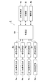
測定装置8は、模型構造物2内を模型移動体1が移動するときにこの模型構造物2内に発生する物理現象を測定する装置である。測定装置8は、模型構造物2内の圧力変動や開口部2eからの気流を測定し、これらの測定結果に基づいて所定の解析処理を実行する。測定装置8は、図3に示すように、圧力変動測定部8a〜8cと、気流測定部8dと、信号処理部8e〜8hと、波形変換部8iと、記憶部8jと、解析部8kと、制御部8mなどを備えている。
FIG. 4 is a layout view of the measuring device of the test apparatus according to the embodiment of the present invention, FIG. 4 (A) is a side view, and FIG. 4 (B) is a plan view.
The measuring
圧力変動測定部8a〜8cは、模型構造物2内の圧力変動を測定する手段であり、模型構造物2内に配置された圧力センサ(圧力計)やマイクロホンなどである。圧力変動測定部8a〜8cは、模型構造物2内を模型移動体1が移動するときにこの模型構造物2内に発生する圧力変動を測定する。圧力変動測定部8a〜8cは、図4に示すように、模型構造物2の長さ方向の略中央に配置されており、圧力変動測定部8aは開口部2e近傍の屋根部2dの下面に固定されており、圧力変動測定部8bは一方の側板部2iの内面に固定されており、圧力変動測定部8cは他方の側板部2iの内面に固定されている。圧力変動測定部8a〜8cは、測定した圧力に応じた圧力検出信号を発生して信号処理部8e〜8gに出力する。
The pressure
図3に示す気流測定部8dは、開口部2eからの気流を測定する手段であり、模型構造物2内に配置された風速計などである。気流測定部8dは、模型構造物2内を模型移動体1が移動するときにこの模型構造物2の開口部2eから発生する気流の風速及び風向などを測定する。気流測定部8dは、図4に示すように、開口部2eの長さ方向の中央に図示しない治具によって固定されており、測定した風速及び風向などに応じた気流検出信号を発生して信号処理部8hに出力する。
The
図3に示す信号処理部8e〜8gは、圧力変動測定部8a〜8cの出力信号を処理する手段であり、信号処理部8hは気流測定部8dの出力信号を処理する手段である。信号処理部8e〜8hは、圧力変動測定部8a〜8cが出力する圧力検出信号及び気流測定部8dが出力する気流検出信号を増幅する増幅回路と、増幅後のアナログ信号をディジタル信号に変換するA/D変換器などを備えており、A/D変換後の圧力検出信号及び気流検出信号を制御部8mに出力する。
The
波形変換部8iは、圧力変動測定部8a〜8cが出力する圧力検出信号及び気流測定部8dが出力する気流検出信号を波形に変換する手段である。波形変換部8iは、例えば、圧力変動測定部8a〜8cが出力する圧力検出信号を圧力の時間変化を表す圧力波形に変換したり、気流測定部8dが出力する気流検出信号を風速の時間変化を表す風速波形に変換したりする。記憶部8jは、種々の情報を記憶する手段であり、波形変換部8iによって変換された圧力波形及び風速波形などの種々の情報を記憶するメモリである。
The
解析部8kは、模型構造物2内に発生する物理現象を解析する手段であり、圧力変動測定部8a〜8cの測定結果及び気流測定部8dの測定結果に基づいて模型構造物2内に発生する物理現象を解析する。解析部8kは、例えば、圧力変動測定部8a〜8cが出力する圧力検出信号が設計基準値(設定値)を超えているか否を評価したり、気流測定部8dが出力する気流検出信号が設計基準値(設定値)を超えているか否かを評価したり、圧力や風速が実際の構造物の基準値を超えているか否かを評価したりして、実際の構造物2の構造の妥当性を評価したりする。
The
制御部8mは、測定装置8の種々の動作を制御する中央処理部(CPU)である。制御部8mは、例えば、信号処理部8e〜8hが出力する圧力検出信号や気流検出信号を波形変換部8iに変換させたり、圧力波形や風速波形などを記憶部8jに記憶させたり、圧力波形や風速波形などに基づいて解析部8kに解析処理を実行させたりする。また、制御部8mは、測定結果や演算結果を印刷装置に印刷させたり表示装置に表示させたりする。制御部8mは、測定解析プログラムに基づいて所定の処理を実行するパーソナルコンピュータなどによって構成されている。
The
次に、この発明の実施形態に係る試験装置の動作を説明する。図5は、この発明の実施形態に係る試験装置の動作を説明するためのフローチャートである。
ステップ(以下、Sという)100において、圧力変動測定部8a〜8cが模型構造物2内の圧力変動を測定するとともに、気流測定部8dが開口部2eからの気流を測定する。図1に示す発射装置4が模型移動体1を発射してガイド装置5によってガイドされながら模型移動体1が模型構造物2内を通過する。このとき、図4(B)に実線で示すような中心走行時には、模型移動体1の中心線と模型構造物2の中心線とが一致するように模型移動体1が模型構造物2内を通過する。一方、図4(B)に二点鎖線で示すような偏心走行時には、模型移動体1の中心線と模型構造物2の中心線とが偏心量sだけずれるように模型移動体1が模型構造物2内を通過する。そして、移動体前部1aが通過するときに発生する圧力変動と移動体後部1bが通過するときに発生する圧力変動とを圧力変動測定部8a〜8cが測定するとともに、模型構造物2内を模型移動体1が通過するときに開口部2eから発生する気流の風速及び風向などを気流測定部8dが測定する。
Next, the operation of the test apparatus according to the embodiment of the present invention will be described. FIG. 5 is a flowchart for explaining the operation of the test apparatus according to the embodiment of the present invention.
In step (hereinafter referred to as S) 100, the pressure
S110において、波形変換部8iが圧力波形や風速波形などに変換する。信号処理部8e〜8hが出力する圧力検出信号及び気流検出信号を、圧力波形や風速波形などに波形変換部8iが変換し記憶部8jが記憶する。
In S110, the
S120において、解析部8kが模型構造物2内に発生する物理現象を解析する。解析部8kが圧力波形や風速波形などを記憶部8jから読み出して、模型構造物2内に発生する圧力変動などを解析し、実際の構造物2の構造の妥当性などを評価する。
In S120, the
図6は、この発明の実施形態に係る試験装置の圧力変動測定部の測定結果を一例として示すグラフであり、図6(A)は開口率5%のときの圧力波形を示し、図6(B)は開口率3%のときの圧力波形を示し、図6(C)は開口率1%のときの圧力波形を示す。
図6に示す縦軸は圧力(Pa)であり、横軸は時間(s)である。図6に示す圧力波形は、図2に示す長さL1=1000mm、長さL2=500mm、長さL3=2000mm、長さL4=400mm、高さH1=100mm、幅W1=188.9mm、幅W2=5.8mm、模型移動体長さl=1000mm、図4(A)に示す高さH2=28.6mm、模型移動体1の速度U=300km/h、偏心量s=0(中心走行)であるときに、図4に示す圧力変動測定部8aによって測定された波形である。なお、模型移動体1及び模型構造物2の縮尺は、実物の1/90であり、圧力変動の測定には圧力計(メーカー:豊田工機、型式:PD104K-0.1F)を使用した。
FIG. 6 is a graph showing, as an example, the measurement result of the pressure fluctuation measuring unit of the test apparatus according to the embodiment of the present invention. FIG. 6 (A) shows the pressure waveform when the aperture ratio is 5%. B) shows the pressure waveform when the aperture ratio is 3%, and FIG. 6C shows the pressure waveform when the aperture ratio is 1%.
The vertical axis shown in FIG. 6 is pressure (Pa), and the horizontal axis is time (s). The pressure waveform shown in FIG. 6 is the length L 1 = 1000 mm, the length L 2 = 500 mm, the length L 3 = 2000 mm, the length L 4 = 400 mm, the height H 1 = 100 mm, and the width W 1 shown in FIG. = 188.9 mm, width W 2 = 5.8 mm, model moving body length l = 1000 mm, height H 2 = 28.6 mm shown in Fig. 4A, model moving
図6に示すように、移動体前部1aが通過した先頭部通過時と移動体後部1bが通過した後部部通過時に大きな圧力変動があり、開口率が小さくなるほど圧力のピーク値が大きくなっている。また、先頭部通過時の負圧部と後尾部通過時の正圧部は、開口率が小さくなるほど小さくなっている。図6に示す圧力波形は、模型移動体長さlが実際の列車の長さよりも短いため、図7に示すような圧力がゼロになる3秒から7秒までの波形に相当する部分が表れていない。しかし、図6に示すように、移動体前部1aの通過と移動体後部1bの通過とによって発生する圧力は分離されており、図7に示す実際の圧力波形を概ね模擬していることが確認された。
As shown in FIG. 6, there is a large pressure fluctuation when the moving body
この発明の実施形態に係る試験装置には、以下に記載するような効果がある。
(1) この実施形態では、模型移動体1の移動方向に沿って構造物入口2a側から構造物出口2b側に向かって模型構造物2が開口部2eを有する。このため、全覆上家を有する線路階などを列車が高速で通過する状況を模擬して模型構造物2内に発生する圧力変動などを測定し、実際の駅の仕上げ材や壁面などに与える影響を解析することができる。その結果、駅の強度や仕上げ材に作用する荷重などを予測するために必要な予測解析モデルの検証用データなどを得ることができる。
The test apparatus according to the embodiment of the present invention has the following effects.
(1) In this embodiment, the
(2) この実施形態では、模型構造物2内の圧力変動を圧力変動測定部8a〜8cが測定するため、この圧力変動測定部8a〜8cの測定結果に基づいて実際の駅の仕上げ材や壁面などに加わる圧力を評価することができる。また、この実施形態では、開口部2eからの気流を気流測定部8dが測定するため、この気流測定部8dの測定結果に基づいて実際の駅の仕上げ材や壁面、旅客などに加わる風圧などを評価することができる。さらに、この実施形態では、模型構造物2内に発生する物理現象を解析部8kが解析するため、実際の構造物2の構造の妥当性などを評価することができる。
(2) In this embodiment, since the pressure
この発明は、以上説明した実施形態に限定するものではなく、以下に記載するように種々の変形又は変更が可能であり、これらもこの発明の範囲内である。
(1) この実施形態では、模型移動体1が鉄道車両を模擬した模型車両である場合を例に挙げて説明したが、磁気浮上式鉄道、航空機、自動車などの他の移動体を模擬した模型移動体についてもこの発明を適用することができる。また、この実施形態では、直線状に連続した一つのスリットを開口部2eに形成した場合を例に挙げて説明したがこれに限定するものではない。例えば、直線状、曲線状又はジグザグ状に一つのスリットを形成したり、直線状、曲線状又はジグザグ状に間隔をあけて複数の貫通孔を開口部2eに形成したり、打抜きによって種々の形の貫通孔を形成したパンチングメタルや、薄く細長い板を平行又は格子状に形成したルーバーなどを開口部2eに設置したりすることもできる。
The present invention is not limited to the embodiment described above, and various modifications or changes can be made as described below, and these are also within the scope of the present invention.
(1) In this embodiment, the case where the
(2) この実施形態では、一つの開口部2eを屋根部2dに形成した場合を例に挙げて説明したが、一つの開口部2eを側板部2iに形成したり、屋根部2d及び側板部2iに開口部2eを分けて形成したりすることもできる。また、この実施形態では、圧力変動測定部8a〜8c及び気流測定部8dの両方を測定装置8が備えているが、いずれか一方を省略することもできる。
(2) In this embodiment, the case where one
(3) この実施形態では、一対の側板部2iを底板部2hに対して垂直に形成した場合を例に挙げて説明したが、一対の側板部2iを湾曲又は傾斜させて形成することもできる。また、この実施形態では、底板部2hと側板部2iとによって線路階部2cを構成する場合を例に挙げて説明したが、パイプなどの円筒状部材を利用して線路階部2cを形成し、この円筒状部材の入口側から出口側にスリットを形成することもできる。この場合には、このスリットの幅が均一となるように、スリットの長さ方向に間隔をあけてスペーサなどを挟み込むことができる。
(3) In this embodiment, the case where the pair of
1 模型移動体(模型車両)
1a 移動体前部(先頭部)
1b 移動体後部(後尾部)
2 模型構造物(模型駅)
2a 構造物入口
2b 構造物出口
2c 線路階部
2d 屋根部
2e 開口部
2f 補強部
2h 底板部
2i 側板部
3 試験装置
8 測定装置
8a〜8c 圧力変動測定部
8d 気流測定部
8k 解析部
8m 制御部
1 Model moving body (model vehicle)
1a Mobile body front (head)
1b Moving body rear part (rear part)
2 Model structure (model station)
Claims (6)
前記模型構造物は、前記模型移動体の移動方向に沿って入口側から出口側まで開口部を有し、
前記模型移動体が前記模型構造物内を移動するときに、この模型構造物内に発生する圧力変動を測定する圧力変動測定手段と、
前記圧力変動測定手段の測定結果に基づいて、前記模型構造物内に発生する物理現象を解析する解析手段とを備え、
前記解析手段は、前記圧力変動測定手段が出力する圧力検出信号が設計基準値を超えているか否かを評価し、前記実際の構造物の構造の妥当性を評価すること、
を特徴とする模型構造物の試験装置。 It is a model structure testing device that tests physical phenomena that occur in a model structure when the model moving body that simulates the actual moving body is moved into the model structure that simulates the actual structure. And
The model structure has an opening from the entrance side to the exit side along the moving direction of the model moving body,
Pressure fluctuation measuring means for measuring pressure fluctuation generated in the model structure when the model moving body moves in the model structure;
Analyzing means for analyzing a physical phenomenon generated in the model structure based on the measurement result of the pressure fluctuation measuring means;
The analyzing means evaluates whether a pressure detection signal output from the pressure fluctuation measuring means exceeds a design reference value, and evaluates the validity of the structure of the actual structure;
Model structure testing equipment characterized by
前記模型構造物は、前記模型移動体の移動方向に沿って入口側から出口側まで開口部を有し、
前記模型移動体が前記模型構造物内を移動するときに、前記開口部から発生する気流を測定する気流測定手段と、
前記気流測定手段の測定結果に基づいて、前記模型構造物内に発生する物理現象を解析する解析手段とを備え、
前記解析手段は、前記気流測定手段が出力する気流検出信号が設計基準値を超えているか否かを評価し、前記実際の構造物の構造の妥当性を評価すること、
を特徴とする模型構造物の試験装置。 It is a model structure testing device that tests physical phenomena that occur in a model structure when the model moving body that simulates the actual moving body is moved into the model structure that simulates the actual structure. And
The model structure has an opening from the entrance side to the exit side along the moving direction of the model moving body,
An airflow measuring means for measuring an airflow generated from the opening when the model moving body moves in the model structure;
Analyzing means for analyzing a physical phenomenon generated in the model structure based on the measurement result of the airflow measuring means;
The analysis means evaluates whether or not the airflow detection signal output from the airflow measurement means exceeds a design reference value, and evaluates the validity of the structure of the actual structure;
Model structure testing equipment characterized by
前記模型移動体は、鉄道車両を模擬した模型車両であり、
前記模型構造物は、前記鉄道車両が通過する駅を模擬した模型駅であること、
を特徴とする模型構造物の試験装置。 In the test apparatus for a model structure according to claim 1 or 2,
The model moving body is a model vehicle simulating a railway vehicle,
The model structure is a model station simulating a station through which the rail vehicle passes;
Model structure testing equipment characterized by
前記模型移動体の移動方向に沿って入口側から出口側まで開口部を有する前記模型構造物にこの模型移動体を移動させる移動工程と、
前記模型移動体が前記模型構造物内を移動するときに、この模型構造物内の圧力変動を測定する圧力変動測定工程と、
前記圧力変動測定工程における測定結果に基づいて、前記模型構造物内に発生する物理現象を解析する解析工程とを含み、
前記解析工程は、前記圧力変動測定工程において出力される圧力検出信号が設計基準値を超えているか否かを評価し、前記実際の構造物の構造の妥当性を評価する工程を含むこと、
を特徴とする模型構造物の試験方法。 This is a test method for a model structure that tests the physical phenomena that occur in the model structure when the model moving object that simulates the actual moving object is moved into the model structure that simulates the actual structure. And
A moving step of moving the model moving body to the model structure having an opening from the inlet side to the outlet side along the moving direction of the model moving body;
A pressure fluctuation measuring step for measuring pressure fluctuation in the model structure when the model moving body moves in the model structure;
Based on the measurement result in the pressure fluctuation measurement step, and analyzing the physical phenomenon occurring in the model structure,
The analysis step includes a step of evaluating whether or not a pressure detection signal output in the pressure fluctuation measurement step exceeds a design reference value, and evaluating a validity of the structure of the actual structure,
A test method for a model structure characterized by
前記模型移動体の移動方向に沿って入口側から出口側まで開口部を有する前記模型構造物にこの模型移動体を移動させる移動工程と、
前記模型移動体が前記模型構造物内を移動するときに、前記開口部から発生する気流を測定する気流測定工程と、
前記気流測定工程における測定結果に基づいて、前記模型構造物内に発生する物理現象を解析する解析工程とを含み、
前記解析工程は、前記気流測定工程において出力される気流検出信号が設計基準値を超えているか否かを評価し、前記実際の構造物の構造の妥当性を評価する工程を含むこと、
を特徴とする模型構造物の試験方法。 This is a test method for a model structure that tests the physical phenomena that occur in the model structure when the model moving object that simulates the actual moving object is moved into the model structure that simulates the actual structure. And
A moving step of moving the model moving body to the model structure having an opening from the inlet side to the outlet side along the moving direction of the model moving body;
An airflow measuring step for measuring an airflow generated from the opening when the model moving body moves in the model structure; and
Based on the measurement result in the airflow measurement step, and an analysis step of analyzing a physical phenomenon occurring in the model structure,
The analysis step includes a step of evaluating whether or not an airflow detection signal output in the airflow measurement step exceeds a design reference value, and evaluating a validity of the structure of the actual structure.
A test method for a model structure characterized by
前記模型移動体は、鉄道車両を模擬した模型車両であり、
前記模型構造物は、前記鉄道車両が通過する駅を模擬した模型駅であること、
を特徴とする模型構造物の試験方法。 In the test method of the model structure according to claim 4 or 5,
The model moving body is a model vehicle simulating a railway vehicle,
The model structure is a model station simulating a station through which the rail vehicle passes;
A test method for a model structure characterized by
Priority Applications (1)
| Application Number | Priority Date | Filing Date | Title |
|---|---|---|---|
| JP2009058079A JP4632460B2 (en) | 2009-03-11 | 2009-03-11 | Model structure testing apparatus and testing method |
Applications Claiming Priority (1)
| Application Number | Priority Date | Filing Date | Title |
|---|---|---|---|
| JP2009058079A JP4632460B2 (en) | 2009-03-11 | 2009-03-11 | Model structure testing apparatus and testing method |
Related Parent Applications (1)
| Application Number | Title | Priority Date | Filing Date |
|---|---|---|---|
| JP2004101186A Division JP4308696B2 (en) | 2004-03-30 | 2004-03-30 | Model structure testing apparatus, test method and model structure |
Publications (2)
| Publication Number | Publication Date |
|---|---|
| JP2009122127A JP2009122127A (en) | 2009-06-04 |
| JP4632460B2 true JP4632460B2 (en) | 2011-02-16 |
Family
ID=40814405
Family Applications (1)
| Application Number | Title | Priority Date | Filing Date |
|---|---|---|---|
| JP2009058079A Expired - Fee Related JP4632460B2 (en) | 2009-03-11 | 2009-03-11 | Model structure testing apparatus and testing method |
Country Status (1)
| Country | Link |
|---|---|
| JP (1) | JP4632460B2 (en) |
Cited By (2)
| Publication number | Priority date | Publication date | Assignee | Title |
|---|---|---|---|---|
| CN102226735A (en) * | 2011-04-02 | 2011-10-26 | 西安交通大学 | Tunnel connection method of rapid moulding wind tunnel pressure measuring model |
| JP2016217897A (en) * | 2015-05-21 | 2016-12-22 | 公益財団法人鉄道総合技術研究所 | Analysis method of flow on roof of vehicle inside tunnel |
Families Citing this family (2)
| Publication number | Priority date | Publication date | Assignee | Title |
|---|---|---|---|---|
| JP5458002B2 (en) * | 2010-12-27 | 2014-04-02 | 公益財団法人鉄道総合技術研究所 | Mobile model for launcher |
| CN108760358B (en) * | 2018-08-06 | 2023-08-22 | 中南大学 | Ice and snow wind tunnel system for railway vehicle bogie |
Citations (6)
| Publication number | Priority date | Publication date | Assignee | Title |
|---|---|---|---|---|
| JPH0348741A (en) * | 1989-07-18 | 1991-03-01 | Nippon Sharyo Seizo Kaisha Ltd | Method and device for measuring air resistance of vehicle |
| JP2002071702A (en) * | 2000-08-28 | 2002-03-12 | Shinko Mex Co Ltd | Air current distribution measuring method and air current detection part |
| JP2002082013A (en) * | 2000-09-07 | 2002-03-22 | Railway Technical Res Inst | Model experiment method of tunnel pressure wave |
| JP2002340735A (en) * | 2001-05-16 | 2002-11-27 | Sumitomo Rubber Ind Ltd | Method for simulating gas flow |
| JP2004257230A (en) * | 2003-02-04 | 2004-09-16 | Railway Technical Res Inst | Passing wave damping structure for fixed construction |
| JP2004270345A (en) * | 2003-03-10 | 2004-09-30 | Railway Technical Res Inst | Pressure wave damping structure for fixed construction |
-
2009
- 2009-03-11 JP JP2009058079A patent/JP4632460B2/en not_active Expired - Fee Related
Patent Citations (6)
| Publication number | Priority date | Publication date | Assignee | Title |
|---|---|---|---|---|
| JPH0348741A (en) * | 1989-07-18 | 1991-03-01 | Nippon Sharyo Seizo Kaisha Ltd | Method and device for measuring air resistance of vehicle |
| JP2002071702A (en) * | 2000-08-28 | 2002-03-12 | Shinko Mex Co Ltd | Air current distribution measuring method and air current detection part |
| JP2002082013A (en) * | 2000-09-07 | 2002-03-22 | Railway Technical Res Inst | Model experiment method of tunnel pressure wave |
| JP2002340735A (en) * | 2001-05-16 | 2002-11-27 | Sumitomo Rubber Ind Ltd | Method for simulating gas flow |
| JP2004257230A (en) * | 2003-02-04 | 2004-09-16 | Railway Technical Res Inst | Passing wave damping structure for fixed construction |
| JP2004270345A (en) * | 2003-03-10 | 2004-09-30 | Railway Technical Res Inst | Pressure wave damping structure for fixed construction |
Cited By (2)
| Publication number | Priority date | Publication date | Assignee | Title |
|---|---|---|---|---|
| CN102226735A (en) * | 2011-04-02 | 2011-10-26 | 西安交通大学 | Tunnel connection method of rapid moulding wind tunnel pressure measuring model |
| JP2016217897A (en) * | 2015-05-21 | 2016-12-22 | 公益財団法人鉄道総合技術研究所 | Analysis method of flow on roof of vehicle inside tunnel |
Also Published As
| Publication number | Publication date |
|---|---|
| JP2009122127A (en) | 2009-06-04 |
Similar Documents
| Publication | Publication Date | Title |
|---|---|---|
| Zhang et al. | Oblique tunnel portal effects on train and tunnel aerodynamics based on moving model tests | |
| Li et al. | Experimental study on aerodynamic characteristics of high-speed train on a truss bridge: A moving model test | |
| Malekjafarian et al. | A review of mobile sensing of bridges using moving vehicles: Progress to date, challenges and future trends | |
| Yu et al. | On aerodynamic noises radiated by the pantograph system of high-speed trains | |
| JP4632460B2 (en) | Model structure testing apparatus and testing method | |
| Zhang et al. | Moving model tests on transient pressure and micro-pressure wave distribution induced by train passing through tunnel | |
| CN107200040B (en) | Method and system for determining the vertical profile of a track surface | |
| JP4557908B2 (en) | Vehicle vibration system | |
| KURITA | Development of external-noise reduction technologies for Shinkansen high-speed trains | |
| CN109839441B (en) | Bridge modal parameter identification method | |
| JP6421033B2 (en) | Method, program and system for estimating damage state of structure | |
| Kurita et al. | Reduction of wayside noise from Shinkansen high-speed trains | |
| Zhang et al. | Sound source localisation for a high-speed train and its transfer path to interior noise | |
| CN101900620A (en) | Method for identifying variable boundary cable force of medium or long cable | |
| JP4308696B2 (en) | Model structure testing apparatus, test method and model structure | |
| CN201615872U (en) | Wheel tread flaw detection device | |
| CN105372080B (en) | A kind of tramcar and its embedded tracks Coupled Dynamics test device and method | |
| JP6707037B2 (en) | Aerodynamic model test equipment | |
| Takaishi et al. | Experimental method for wind tunnel tests to simulate turbulent flow on the roof of high-speed trains | |
| Zhang et al. | Detection of damaged supports under railway track using dynamic response of a passing vehicle | |
| JP2011132705A (en) | Prediction arithmetic unit, prediction operation method, and prediction operation program for pressure wave | |
| MacNeill et al. | Measurement of the aerodynamic pressures produced by passing trains | |
| KR101303566B1 (en) | Method for inducing noise characteristics of certain point of train | |
| KR100389164B1 (en) | model train test equipment | |
| MATSUOKA et al. | Resonant bridge detection method by on-board measurement |
Legal Events
| Date | Code | Title | Description |
|---|---|---|---|
| A621 | Written request for application examination |
Free format text: JAPANESE INTERMEDIATE CODE: A621 Effective date: 20090311 |
|
| TRDD | Decision of grant or rejection written | ||
| A01 | Written decision to grant a patent or to grant a registration (utility model) |
Free format text: JAPANESE INTERMEDIATE CODE: A01 Effective date: 20101115 |
|
| A01 | Written decision to grant a patent or to grant a registration (utility model) |
Free format text: JAPANESE INTERMEDIATE CODE: A01 |
|
| A61 | First payment of annual fees (during grant procedure) |
Free format text: JAPANESE INTERMEDIATE CODE: A61 Effective date: 20101115 |
|
| R150 | Certificate of patent or registration of utility model |
Ref document number: 4632460 Country of ref document: JP Free format text: JAPANESE INTERMEDIATE CODE: R150 Free format text: JAPANESE INTERMEDIATE CODE: R150 |
|
| FPAY | Renewal fee payment (event date is renewal date of database) |
Free format text: PAYMENT UNTIL: 20131126 Year of fee payment: 3 |
|
| FPAY | Renewal fee payment (event date is renewal date of database) |
Free format text: PAYMENT UNTIL: 20131126 Year of fee payment: 3 |
|
| S533 | Written request for registration of change of name |
Free format text: JAPANESE INTERMEDIATE CODE: R313533 |
|
| FPAY | Renewal fee payment (event date is renewal date of database) |
Free format text: PAYMENT UNTIL: 20131126 Year of fee payment: 3 |
|
| R350 | Written notification of registration of transfer |
Free format text: JAPANESE INTERMEDIATE CODE: R350 |
|
| LAPS | Cancellation because of no payment of annual fees |