JP4632396B2 - MEMORY AND MEMORY STORAGE METHOD - Google Patents
MEMORY AND MEMORY STORAGE METHOD Download PDFInfo
- Publication number
- JP4632396B2 JP4632396B2 JP2003160987A JP2003160987A JP4632396B2 JP 4632396 B2 JP4632396 B2 JP 4632396B2 JP 2003160987 A JP2003160987 A JP 2003160987A JP 2003160987 A JP2003160987 A JP 2003160987A JP 4632396 B2 JP4632396 B2 JP 4632396B2
- Authority
- JP
- Japan
- Prior art keywords
- information
- storage area
- data
- stored
- memory
- Prior art date
- Legal status (The legal status is an assumption and is not a legal conclusion. Google has not performed a legal analysis and makes no representation as to the accuracy of the status listed.)
- Expired - Fee Related
Links
Images


Description
【0001】
【発明の属する技術分野】
本発明は、メモリ及びメモリの記憶方法に関するものである。
【0002】
【従来の技術】
従来、電子写真技術を用いた複写機、レーザービームプリンタなどにおいて、画像形成に用いる様々な部品をユニット化し、そのユニットを装置本体に着脱可能に装着し、そのユニットが寿命に到達する毎に交換することにより、画像形成装置の使用及び管理を行う装置が提供されている。
【0003】
この画像形成に用いるユニットとは、図10に示すように、像担持体である感光ドラム、その感光ドラムの表面を一様に帯電するための帯電部材としての帯電ローラ、及び感光ドラムに現像剤であるトナーを供給するための現像部材としての現像ローラと現像剤収容容器から構成される現像装置が一つにユニット化されたカートリッジであり、装置本体に着脱可能に装着されるものである。
【0004】
近年、このカートリッジに不揮発性メモリ(例えば、EEPROM、以下メモリと言う)を搭載したメモリ内蔵カートリッジが利用されつつある。このメモリ内蔵カートリッジには、ドラムの回転時間の累積時間やトナー残量などのカートリッジの寿命に関する情報が蓄えられており、通信によってその情報を取得したプリンタ制御部がトナーカートリッジの寿命を判断し、コントローラからのプリント信号のキャンセルなどの判断を行っている。
【0005】
このカートリッジのメモリへは、データの書き込みと読み出しの両方の作業が可能である。前述したプリンタ制御部の指示に基づいてメモリへのデータの書き込みと読み出しを実行することが可能である。また、書き込みを行った後、その後、書き換える可能性のないデータに関しては、データを書き込み禁止の状態にする作業(以下、ロック)が可能になっている。一旦データのロックを行うと、その後、該当するエリアに対して書き込みを行えず、読み出しのみが可能となる。データのロックは、1バイト毎、2バイト毎、4バイト毎、40バイト毎などのように、メモリによって一括してロック可能なデータサイズが異なる。
【0006】
また、メモリにおけるデータ領域の全てに関してロック可能なデータサイズが一致しているとは限らず、メモリ内の領域の一部は1バイト毎、異なる一部は4バイト毎といったように、メモリ内でロック可能なデータサイズの異なるメモリも存在する。
【0007】
このメモリへ格納するデータの構造には様々なものが考えられるが、その一つにデータの信頼性を高めるためのダブルバッファ構成がある。これはデータ全体をメインバッファとバックアップバッファに分け、双方に同一の意味を表すデータを保存し、双方の一致をもって該当するデータを信頼性のあるものとして利用する方法である。
【0008】
また、信頼性を高める手法として、ダブルバッファ構成とした上で各バッファにチェックサムを設ける方法もある。この方法によれば、バッファ毎にデータを更新する度にチェックサムも更新して保存する。また、本体起動時などのメモリデータ使用時にチェックサムを確認し、チェックサムに異常が発見された場合、チェックサムに異常のなかったバッファのデータを用いて、チェックサムに異常が発見されたバッファのデータをすべて修復することにより、その後もメモリを使用することが可能となる。
【0009】
【発明が解決しようとする課題】
しかしながら、上記従来例では、メモリ上のデータは、その後書き換えが行われないと判断した時点でデータロックが可能であるが、ビットで表現可能な2つの状態しか取り得ない情報でも、データロックを行うためにはメモリの内部構造上、例えば1バイト(8ビット)単位などの所定単位で領域をロックすることになる。即ち、ロック可能な最小単位までデータサイズを拡張する必要があるため、メモリのデータ領域の使用効率が落ち、データ領域の無駄が生じる。
【0010】
また、メモリに格納するデータの構成をダブルバッファ構成とし、更に各バッファにチェックサムを設けた場合、データの保存の順番は以下のようになる。
(1)メインバッファのデータ更新
(2)メインバッファのチェックサム更新
(3)メインバッファのデータロック
(4)バックアップバッファのデータ更新
(5)バックアップバッファのチェックサム更新
上記(2)の段階でエラーが発生した場合、従来の方法だとバックアップバッファのデータを用いてメインバッファのデータを修復する。そして、再びデータの書き換え指示が発行されたときに該当する領域のデータを再度書き換えることになる。例えば、データの書き換え指示の発行間隔が非常に長いデータであった場合、一旦はデータ変更タイミングが到来したにもかかわらず、再びデータ変更タイミングが到来するまでデータの書き換えが実行されないことになる。
【0011】
本発明は、上記課題を解決するためになされたもので、メモリのデータ領域を効率良く使用できるメモリ及びメモリの記憶方法を提供することを目的とする。
【0012】
また、本発明の他の目的は、メモリのデータ異常が発生した場合に、メモリの状態を最新の状態に近い形で修復できることである。
【0013】
【課題を解決するための手段】
上記目的を達成するために、本発明は、画像形成装置に着脱可能に装着され、現像剤を収容するカートリッジに搭載されるメモリであって、前記カートリッジに収容される前記現像剤の量に関する情報を記憶する第1の記憶領域と、前記第1の記憶領域に記憶された情報をバックアップするためのバックアップ情報を記憶する第2の記憶領域とを有するメモリにおいて、前記第1の記憶領域に、前記現像剤の残量を示す第1情報と前記現像剤が少なくなったことを示す第2情報の夫々を、所定ビット数からなるバイトサイズの情報として記憶し、前記第2の記憶領域に、前記第1情報の前記バックアップ情報として、前記第1の記憶領域の前記第1情報と同じ前記バイトサイズの情報として記憶し、前記第2情報の前記バックアップ情報として、前記第1の記憶領域に前記第2情報が記憶されたことを示す1ビットの情報を記憶することを特徴とする。
【0017】
【発明の実施の形態】
以下、図面(図1及び図2)を参照しながら本発明に係る実施の形態を詳細に説明する。
【0018】
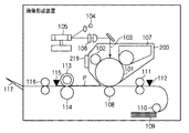
図1は本発明を適用可能な電子写真技術を用いたレーザプリンタの一例を示す概要図である。図1において、101は静電潜像担持体としての感光ドラムであり、この感光ドラム101の上方にはその感光ドラム101の表面を一様に帯電せしめる帯電ローラ102がその表面に当接している。この帯電ローラ102の当接位置よりも感光ドラム101の回転方向下流側の帯電された表面には発光手段によって光ビーム103が照射されるように構成されている。この発光手段は、光ビーム103を発する半導体レーザ104と、その光ビーム103を上述の表面上に走査させるスキャナ105と、その光ビーム103を上述の表面でスポットを形成するよう調整する光学レンズ106から構成されている。そして、画像データに基づいて光ビーム103を照射することによって上述の表面に静電潜像を形成させる。その静電潜像は、光ビーム103の照射位置よりも更に感光ドラム101の回転方向下流側で感光ドラム101に当接するように配設された現像装置107によってトナー像として現像される。
【0019】
そのトナー像は、感光ドラム101の下方で感光ドラム101に対向するように配設された転写ローラ108によって転写材としての用紙P上に転写される。用紙Pは感光ドラム101の前方(図1において右側)の用紙カセット109内に収納されているが、手差しでも給紙が可能である。用紙カセット109端部には、給紙ローラ110が配設されており、この用紙カセット109内の用紙Pを搬送路へ送り込む。上述の給紙ローラ110と転写ローラ108の間の搬送路中には用紙Pの斜行補正並びに感光ドラム101上の画像形成と用紙搬送の同期をとるためのレジストローラ111が配設されており、上述した転写位置へ所定のタイミングで用紙Pを送り込む。尚、上述のレジストローラ111と給紙ローラ110との間にはレジスト紙有無検知センサ112が配設されており、用紙Pの有無を検知するように構成されている。
【0020】
以上のようにして、未定着トナー像が転写された用紙Pは更に感光ドラム101後方(図1では左側)の定着装置へと搬送される。この定着装置は内部に定着ヒータ(図示せず)を有する定着ローラ113とその定着ローラ113に圧接するように配設された加圧ローラ114で構成されており、転写され搬送されてきた用紙Pを定着ローラ113と加圧ローラ114の圧接部にて加圧しながら加熱することにより、用紙P上の未定着トナー像を定着させる。圧接部の後方には、圧接部から用紙Pが排出されることを確認する排紙紙有無検知センサ115が配設されている。更に、この排紙紙有無検知センサ115の後方には排紙ローラ116が配設されており、定着された用紙Pを排紙トレイ117に排出させる。
【0021】
次に、このような機構部を有する電子写真プリンタの制御部について、図2に基づいて説明する。図2において、201は本電子写真プリンタの外部に配設されたホストコンピュータで、ユーザ等の操作により作成された画像コードデータをパラレル或いはシリアルのデータとして通信回線202を通してコントローラ203へ送出する。コントローラ203は、ホストコンピュータ201から送出されてきた画像コードデータを展開してプリンタへ送出すべき画像情報に変換すると共に、プリンタ制御部204に対しコマンドを指示したり、プリンタ制御部からの内部データをステータスとして読み取ったり、プリンタ制御部にプリント開始要求や予給紙要求を行う。また、コントローラ203は画像出力タイミングとプリンタ内の用紙搬送との同期をとるための同期信号の制御も行うものであり、プリンタ内部に存在する場合とホストコンピュータ内に存在する場合とがある。また、プリンタ制御部204には、プリンタの様々なモード設定(例えば画像域のマージン設定など)をユーザが操作するためのオペレーションパネル205が接続されている。
【0022】
ホストコンピュータ201と接続されたコントローラ203は、上述したようにプリンタ制御部204とのデータの送受信を行う。プリンタ制御部204は、図1の各機構部の駆動/停止のタイミング制御及び各センサの入力情報を読み取るため、搬送系駆動部206、高圧系駆動部207、光学系駆動部208、定着ヒータ制御部209、及びセンサ入力部210と接続されている。
【0023】
先ず、搬送系駆動部206は、各種モータ211及び各種ローラ212の駆動/停止を、次に高圧系駆動部207は、帯電213、現像214、転写215の駆動/停止をそれぞれプリンタ制御部204の指示に基づいて行う。また、光学系駆動部208は、レーザ104、スキャナ105の駆動/停止を、さらに定着ヒータ制御部209は、定着ヒータ216の駆動/停止をそれぞれプリンタ制御部204の指示に基づいて行うようになっている。そして、センサ入力部210は、レジスト紙有無検知センサ112及び排紙紙有無検知センサ115の情報を読み取り、プリンタ制御部204へ情報を提供するセンサ入力部である。
【0024】
次に、本発明の装置における動作について説明する。先ず、プリンタは、コントローラ203からのプリント信号待ちの状態となる。仮に、プリント信号を受信していない状態であればコントローラ203からの予給紙要求の有無をチェックし、予給紙要求を受けた場合にはモータ211を駆動した後給紙動作を開始する。その後用紙Pがレジスト紙有無検知センサ112に到着するか否かをチェックし、センサ112が用紙先端を検出すると所定時間ウエイトした後給紙動作を停止する。その時点でモータ211を停止してプリント信号待ちの状態となる。プリント信号を受けると再度モータ211を駆動するときにスキャナ105、各高圧を立ち上げる。スキャナモータ(図示せず)が規定回転に達すると、用紙Pは既に予給紙されているのでレジスト紙有無検知センサ112は紙の有無をチェックする。この時点でレジスト紙有無検知センサ112に用紙Pが存在しない場合は異常処理(ジャム処理等)を行う。また、センサ112に用紙Pが存在している場合にはコントローラ203に対して垂直同期信号を出力する。その後垂直同期信号を受けると感光ドラム101へ画像書き込みを許可し、レジストローラ111を駆動する。そして、排紙紙有無検知センサ115が用紙後端を検出してから所定時間ウェイトした後、高圧立ち上げ及びスキャナモータを停止してからローラ駆動系のモータを停止して印字処理を停止する。
【0025】
本実施形態では、図1に示すように、像担持体である感光ドラム101、感光ドラム101の表面を一様に帯電するための帯電部材としての帯電ローラ102、及び感光ドラム101に現像剤であるトナーを供給するための現像手段である現像装置107を一つのユニットとし、着脱可能なカートリッジ200を構成している。
【0026】
尚、画像形成に用いるユニットとしては、上記のような形態に限らず、例えば現像手段107と感光体ドラム101をユニット化したものや、現像手段のみをユニット化したものでも良い。
【0027】
カートリッジ200には、不揮発性の記憶手段としてのEEPROM219が設けられており、そのEEPROM219には、ドラムの回転時間の累積時間やトナー残量などカートリッジ200の寿命に関する情報が蓄えられており、通信によってその情報を取得した装置本体のプリンタ制御部204がカートリッジ200の寿命を判断し、コントローラ203からのプリント信号のキャンセルなどの判断を行っている。
【0028】
尚、ユニット化されたカートリッジ200は、画像形成装置本体に着脱可能に構成されており、カートリッジ200が画像形成装置本体に装着されると、EEPROM219と図2に示すプリンタ制御部204とがデータ通信可能な状態となる。ここで図示してはいないが、データ通信方式としてはコネクタ接続による通信や、無線方式による通信など、EEPROMなどの不揮発性メモリに対するデータの送受信を実行可能にするものであれば良い。
【0029】
次に、図面(図3、図4、図5)を参照しながら本実施形態における電子写真プロセスを用いた画像形成装置本体に着脱可能に装着して使用されるプロセスカートリッジに使用履歴、プロセス条件等の画像形成に関するデータを記録する不揮発性メモリのデータ領域を効率良く使用する方法について説明する。本実施形態では、メインバッファとバックアップバッファとを備え、メインバッファに保存するデータはビット情報(データ)をロック可能なデータサイズに拡張して保存するが、バックアップバッファに保存するデータはデータのロックを行わず、バックアップバッファに保存される他の本来ならビット単位で済む情報と共にビット単位のままシュリンクして保存する。
【0030】
図3は、図1、図2に示したEEPROM219のデータ領域の割当を簡易的に示す図である。まず、メインバッファとバックアップバッファのそれぞれに1バイトのチェックサム情報を持つ場合について考える。図3に示す(a)は従来例におけるデータの割り当てを示す図である。図3に示す(a)のように、データのロックが可能な最小の単位が1バイトであった場合、8種類のビット情報を各々1バイトずつに拡張して割り当てている。この例では、メインバッファに関して、8バイトのデータ領域と1バイトのメインバッファのチェックサムデータの領域を確保している。そして、バックアップバッファに関しても同様に8バイトのデータ領域と1バイトのチェックサムデータの領域を確保している。つまり、8ビット分のデータを保存するために、メモリのデータ領域を18バイト使用している。
【0031】
一方、図3に示す(b)は本実施形態におけるデータの割当てを示す図である。図3に示す(b)のように、メインバッファに関しては、図3に示す(a)と同様に、8バイトのデータ領域と1バイトのチェックサムデータの領域を確保している。しかし、バックアップバッファに関してはビット情報(データ)をそのままビット単位で取り扱い、他のビット情報と共にシュリンクして1バイトの領域に保存するものである。これにより、チェックサムを含めてもバックアップバッファは2バイトのデータサイズでデータを保存できる。
【0032】
上述の場合に使用される各々のデータサイズを比較すると、図3に示す(a)は18バイトで、図3に示す(b)は1バイトであり、約39%のメモリ領域の使用効率の向上が達成される。
【0033】
尚、図3に示す(c)はEEPROM219に記憶するデータを示す図である。EEPROM219には、例えばプロセスカートリッジの使用履歴であるトナー残量が少である状態、トナー残量が無しである状態などの状態を示す情報、又は、状態を示す情報以外に、例えばトナー使用量の情報(現像装置内のトナーの残量であり例えばgや%などで示される値)、ドラムの使用量の情報(ドラムの回転時間、プリント枚数値)の情報など複数記憶されており、トナー残量少、トナー残量無しなどの状態(セット/リセット状態)を示す情報のバックアップはビット単位でバックアップを行い、それ以外のトナーの使用量やドラムの使用量などの情報はメインバッファと同じ情報を同じバイト単位でバックアップする。即ち、プロセスカートリッジのEEPROM219の記憶領域のバックアップバッファは、この図3に示す(c)のように、ビット単位でバックアップする記憶領域と、バイト単位でバックアップする記憶領域を有している。
【0034】
次に、上述したメモリのデータ異常が発生した場合に、メモリの状態を最新の状態に近い形で修復を行う方法について説明する。
【0035】
本実施形態では、ビット情報をデータのロック可能な最小のサイズ、例えば1バイトサイズにまで拡張した場合、拡張されたデータが取り得る値は、ビット情報のセットされた状態(データが書き込まれた状態)を表す任意の値と、ビット情報(データ)のリセットされた状態(データが書き込まれる前の状態)を表す任意の値の2つのみで、それ以外の値は異常が発生した状態と考えることができる。更に、書き換え後はロックする領域のデータであれば、該当する領域のデータの変更は、デフォルト値から所定値への変更(デフォルト値がセット状態ならば所定値はリセット状態、デフォルト値がリセット状態ならば所定値はセット状態)のみであり、変更後の値に意味がある。つまり、異常が発生した場合に、該当する領域のデータが所定の値になる確率は、1バイトに拡張された場合では1/256、2バイトに拡張された場合でも1/65536である。これは、チェックサムが異常を表していても、拡張されたデータが所定値を示していた場合、そのデータに関しては異常が示されたバッファの値をそのまま使用しても問題ないレベルであると判断することができる。
【0036】
即ち、異常が発生したとき、異常が発生した領域のデータが、00hやFFhとなるメカニズムが明らかになっている場合は、ビット情報(データ)の変化後の値を意味する所定値を00hやFFh(1バイトに拡張した場合)を避けることで更に信頼度を向上させることができる。
【0037】
以上のことから、例えば1バイトに拡張した場合、メインバッファのデータに関してチェックサム異常が判断されたとしても、メインバッファのデータが所定値であったならば、その領域に関してはバックアップバッファの値を用いて修復せずにメインバッファの値をそのまま使用する。
【0038】
図4は、本実施形態におけるデータ修復の様子を示す図である。ここで、説明を簡単化するために、各データはリセット状態からセット状態へと変化するものとする。
【0039】
図4に示す(a)は異常が発生した状態での各バッファとチェックサムの状態を示している。この例では、メインバッファのデータ領域1〜8は、データ領域1,2がリセット状態を示す値(以下、「リセット状態」)であり、データ領域3,4がセット状態を示す値(以下、「セット状態」)であり、データ領域5,6が「セット状態」でも「リセット状態」でもない異常な値(以下、「異常値」)であり、データ領域7,8が「セット状態」で更にロックされた状態(以下、「ロック状態」)である。
【0040】
尚、メインバッファは、データ領域1〜8のチェックサム(総和)を計算してみると、チェックサム保存領域に保存されている値と計算値が一致しないものとする。また、バックアップバッファは、データ領域1〜8に相当する情報がそれぞれリセット、セットの順であり、バックアップバッファのチェックサムは計算値と保存されている値が一致しているものとする。
【0041】
図5は、本実施形態におけるデータ修復処理を示すフローチャートである。このフローチャートの制御は、図2のプリンタ制御部204内のROMなど(図示していない)に記憶されたプログラムによって実行されるものである。
【0042】
まず、ステップS501において、メインバッファのデータ領域及びバックアップバッファのビット領域を示すインデックスnを“1”に初期化する。次に、ステップS502において、メインバッファのデータ領域(n)がロック状態かを判定し、ロック状態でなければステップS503へ進み、メインバッファのデータ領域(n)がセット状態かを判定する。その結果、セット状態でなければステップS504へ進み、バックアップバッファのビット領域(n)がセット状態かを判定する。その結果、ビット領域(n)がセット状態でなければステップS505へ進み、メインバッファのデータ領域(n)をリセット状態に書き換える。次に、ステップS506において、メインバッファのチェックサムを算出し、チェックサム保存領域のデータを書き換える。
【0043】
このように、ステップS502〜S505の場合は、メインバッファのデータ領域(n)がリセット状態或いは異常値で、かつバックアップバッファのビット領域(n)のビット情報がリセット状態に相当し、図4に示す(a)の例では、データ領域1のリセット状態とデータ領域5の異常値が図4に示す(b)のようにリセット状態に書き換えられる。
【0044】
また、上述のステップS504において、バックアップバッファのビット領域(n)がセット状態であればステップS507へ進み、メインバッファのデータ領域(n)をセット状態に書き換える。次に、ステップS508において、メインバッファのチェックサムを算出し、チェックサム保存領域のデータを書き換える。そして、ステップS509において、メインバッファのデータ領域(n)をロック状態とする。
【0045】
このように、ステップS504→S507の場合は、メインバッファのデータ領域(n)がリセット状態或いは異常値で、かつバックアップバッファのビット領域(n)のビット情報がセット状態に相当し、図4に示す(a)の例では、データ領域2のリセット状態とデータ領域6の異常値がセット状態に書き換えられ、更に図4に示す(b)のように、それぞれロック状態に書き換えられる。
【0046】
また、上述のステップS503において、メインバッファのデータ領域(n)がセット状態であればステップS510へ進み、メインバッファのデータ領域(n)をロック状態とする。次に、ステップS511において、メインバッファのチェックサムを算出し、チェックサム保存領域のデータを書き換える。そして、ステップS512において、バックアップバッファのビット領域(n)をセット状態に書き換える。次に、ステップS513において、バックアップバッファのチェックサムを算出し、チェックサム保存領域のデータを書き換える。
【0047】
このように、ステップS503→S510の場合は、メインバッファのデータ領域(n)がセット状態に相当し、図4に示す(a)の例では、データ領域3とデータ領域4のセット状態が図4に示す(b)のように、それぞれロック状態に書き換えられる。そして、バックアップバッファのビット領域3のビット情報がセット状態に書き換えられる。
【0048】
また、上述のステップS502において、メインバッファのデータ領域(n)がロック状態であればステップS516へ進み、メインバッファのデータ領域(n)がセット状態かを判定する。その結果、メインバッファのデータ領域(n)がセット状態でなければ、このメモリは復帰不可能と判断する。つまり、本実施形態では、メインバッファのデータをロック状態とするのは、上述のステップS509及びS510の処理だけであり、これらの場合、メインバッファのデータは共にセット状態であるためである。また、メインバッファのデータ領域(n)がセット状態ならばステップS511へ進み、上述の処理を行う。
【0049】
このように、ステップS502→S516の場合は、メインバッファのデータ領域(n)がロック状態に相当し、図4に示す(a)の例では、データ領域7とデータ領域8の場合であり、図4に示す(b)のように、バックアップバッファのビット領域7のビット情報がセット状態に書き換えられる。
【0050】
次に、上述の処理が終了すると、ステップS514において、インデックスnを更新し、ステップS515で全ての修復が終了したか判断し、終了していれば処理を終了するが、終了していなければ上述のステップS502に戻り、上述の処理を繰り返す。
【0051】
メインバッファのチェックサムが計算値と合致せず、バックアップバッファのチェックサムは計算値と合致していた場合の、データ修復の規則は以下のようにまとめられる。
(1)基本的にバックアップバッファの値を用いて修復する。メインバッファの値をセット状態にするときは、データのロックも行う。但し、以下の場合は例外とする。
(2)メインバッファの値がセット状態の時は、バックアップバッファのデータをセット状態にする。メインバッファの値をロックする。
(3)メインバッファの値がロック状態の時は、バックアップバッファのデータをセット状態にする。
【0052】
[第1の実施形態]
次に、図面(図6、図8、図9)を参照しながら本発明に係る第1の実施形態を詳細に説明する。
【0053】
図6は、第1の実施形態における処理を説明するための図である。第1の実施形態では、プロセスカートリッジの内部に設けられたメモリのデータ領域が00h〜FFhで表される256バイトの領域であり、1バイト毎にデータの書き換え禁止の設定が可能であるものとする。また、メモリ上に保存されるビット情報(データ)として、例えばプロセスカートリッジ内の現像剤の残量が減少したことを表す「トナー残量少」と、現像剤の残量がなくなったことを表す「トナー残量なし」があるとする。
【0054】
図6に示す(a)のように、ダブルバッファの一方は、メインバッファとしてビット情報(データ)毎にデータの書き換え禁止の設定を行うために、メモリの書き換え禁止の可能な最小データサイズである1バイトに合わせて、1バイトに拡張して保存するために、00hの領域に「トナー残量少」を、01hの領域に「トナー残量なし」を割り当てる。更に、任意に設定するビット情報(データ)のリセット状態を示すバイト情報を「48h」、セット状態を示すバイト情報を「CAh」とする。
【0055】
ダブルバッファのもう一方は、バックアップバッファとして「トナー残量少」と「トナー残量なし」の2つのビット情報(データ)をシュリンクしてアドレス10hの1つの領域に割り当てる。このアドレス10hの領域の最上位ビットを「トナー残量少」に、次の上位ビットを「トナー残量なし」とする。またビット情報(データ)はセット状態を「1」で、リセット状態を「0」で表す。
【0056】
新品のプロセスカートリッジでは、「トナー残量少」と「トナー残量なし」は共にリセット状態なので、メモリ上のデータはアドレス00hがリセット状態を表す「48h」、アドレス01hがリセット状態を表す「48h」、シュリンクした情報であるアドレス10hの最上位ビットが「0」で、次の上位ビットは「0」である。
【0057】
ここで、このプロセスカートリッジを使用して現像剤が減少し、所定量以下になった時に「トナー残量少」と判断されると、メモリ上のデータはアドレス00hがセット状態を表す「CAh」となり、アドレス01hがリセット状態を表す「48h」、シュリンクした情報であるアドレス10hの最上位ビットが「1」となり、次の上位ビットは「0」である。ここでアドレス00hのデータはロックされ、書き換え禁止とされる。
【0058】
更に、このプロセスカートリッジを使用して現像剤が減少し続け、図6に示す(b)のように、現像剤の残量が所定量以下になった時に「トナー残量なし」と判断されると、メモリ上のデータはアドレス00hがセット状態を表す「CAh」のままで、アドレス01hがセット状態を表す「CAh」となり、シュリンクした情報であるアドレス10hの最上位ビットが「1」のまま、次の上位ビットが「1」となる。ここでアドレス01hのデータはロックされ、書き換え禁止とされる。
【0059】
[チェックサム]
ダブルバッファの各々は、エラーチェックの手段としてチェックサムデータを備えている。メインバッファのチェックサムデータはアドレス0Fhの領域に、バックアップバッファのチェックサムデータはアドレス11hの領域にそれぞれ保存されているものとする。ここで、メインバッファのチェックサムデータは、メインバッファに保存されている「トナー残量少」或いは「トナー残量なし」が変化したときにメインバッファのデータを書き換えた後、チェックサム算出手段にて算出された値に書き換えられる。バックアップバッファのチェックサムは、バックアップバッファに割り当てられているアドレス10hの領域に保存されるビット情報(データ)「トナー残量少」と「トナー残量なし」が書き換えられると、チェックサム算出手段によって算出された値に書き換えられる。
【0060】
ここで、電源投入後やプロセスカートリッジを入れ替えられたことを検出すると、画像形成装置はメモリ上のデータ領域の値を全て読み出して、各バッファのチェックサムデータ領域に記憶されているチェックサムデータがプリンタ制御部204内のチェックサム算出手段によって算出されたチェックサム(読み出した値を加算した値)と一致するかを判定する。ここで、ダブルバッファの一方で、チェックサムデータと算出したチェックサムが一致しなかった場合には、ダブルバッファのもう一方のチェックサムデータと算出値を比較する。その結果、もう一方のバッファのチェックサムも一致しなかった場合は、このメモリのデータを修復することはできない。しかし、もう一方のバッファのチェックサムが一致すれば、このメモリのデータはチェックサムの一致したバッファのデータを用いて修復することができる。つまり、メインバッファとバックアップバッファの構成が上述のようになっており、チェックサムが一致しなかったのがメインバッファであった場合、データの修復は以下の手順で行われる。
【0061】
図8は、第1の実施形態におけるデータ修復処理を示すフローチャートである。また、図9は、メイン及びバックアップバッファのデータをデータ修正しロックする場合の一例を示す図である。
【0062】
まず、ステップS801において、メインバッファのデータ領域(n)及びバックアップバッファのビット領域(n)を示すインデックスnを"1"に初期化する。次に、ステップS802において、メインバッファのデータ領域(1)がロック状態かを判定し、ロック状態でなければステップS803へ進み、メインバッファのデータ領域(1)アドレス00hの領域にトナー量少を示す48hがセットされているかを判定する。その結果、セット状態でなければステップS804へ進み、バックアップバッファのビット領域(1)のビットがセットされているかを判定する。その結果、セット状態でなければ、ステップS805へ進み、メインバッファのデータ領域(1)のアドレス00hの領域をリセット状態に書き換える。次に、ステップS806において、メインバッファのチェックサムを算出し、チェックサム保存領域のデータを書き換える。
【0063】
このように、ステップS802〜S806の場合は、メインバッファのデータ領域(1)アドレス00hがリセット状態或いは異常値で、かつ、バックアップバッファのデータ領域(1)のビット情報がリセット状態に相当している場合、メインバッファのデータ領域(1)アドレス00hのデータをリセット状態(00h)に書き換える。次に、メインバッファのチェックサムを算出し、チェックサム保存領域のデータを書き換える。
【0064】
また、上述のステップS804において、バックアップバッファのビット領域(1)のビット情報がセット状態であればステップS807へ進み、メインバッファのデータ領域(1)アドレス00hのデータをセット状態(CAh)に書き換える。次に、ステップS808において、メインバッファのチェックサムを算出し、チェックサム保存領域のデータを書き換える。そして、ステップS809において、メインバッファのデータ領域(1)アドレス00hをロック状態とする。
【0065】
このように、ステップS804→S807の場合は、メインバッファのデータ領域(1)アドレス00hがリセット状態或いは異常値で、かつバックアップバッファのビット領域(1)のビット情報がセット状態に相当している場合、メインバッファのデータ領域(1)アドレス00hのデータをセット状態(CAh)に書き換えられ、更にアドレス00hの領域はロック状態に書き換えられる。
【0066】
図9は、このステップS804→S807の場合のメインバッファ及びバックアップバッファの状態の一例を示すものである。
【0067】
また、上述のステップS803において、メインバッファのデータ領域(1)アドレス00hがセット状態であればステップS810へ進み、メインバッファのデータ領域(1)アドレス00hをロック状態とする。次に、ステップS811において、メインバッファのチェックサムを算出し、チェックサム保存領域のデータを書き換える。そして、ステップS812において、バックアップバッファのビット領域(1)のビット情報をセット状態に書き換える。次に、ステップS813において、バックアップバッファのチェックサムを算出し、チェックサム保存領域のデータを書き換える。
【0068】
このように、ステップS803→S810の場合は、メインバッファのデータ領域(1)アドレス00hがセット状態(CAh)に相当している場合であり、バックアップバッファのビット領域(1)のビット情報がセット状態に書き換えられる。
【0069】
また、上述のステップS802において、メインバッファのデータ領域のアドレス00hがロック状態であればステップS816へ進み、メインバッファのデータ領域のアドレス00hがセット状態かを判定する。その結果、セット状態でなければ、このメモリは復帰不可能と判断する。つまり、第1の実施形態では、メインバッファのデータをロック状態とするのは、上述のステップS809及びS810の処理だけであり、これらの場合、メインバッファのデータは共にセット状態(CAh)であるためである。また、メインバッファのデータ領域の00hがセット状態ならばステップS811へ進み、上述の処理を行う。
【0070】
このように、ステップS802→S816の場合は、メインバッファのデータ領域(1)がロック状態に相当している場合、メインバッファのデータ領域(1)アドレス00hがセット状態かを判定し、その結果、セット状態でなければ復帰不可能(NG)と判定する。
【0071】
次に、上述の処理が終了すると、ステップS814において、インデックスnを更新し、ステップS801で初期化したインデックスn(=1)を更新する(インクリメントしてn=2となる)。そして、ステップS815で全ての修復が終了したか判断し、終了していれば処理を終了するが、終了していなければ、上述のステップS802に戻り、上述の処理を繰り返す。
【0072】
以上の手順を実行することにより、より最新の情報を反映したデータの修復が行える。
【0073】
これらの手段の実現は、コントローラ上のマイクロコンピュータに設定されたプログラムの形で実現される。
【0074】
[第2の実施形態]
次に、図面(図7)を参照しながら本発明に係る第2の実施形態を詳細に説明する。
【0075】
第2の実施形態におけるプロセスカートリッジに搭載されたメモリ上のデータ構成は、第1の実施形態で説明したデータ構成と同様である。ここでは、第1の実施形態と異なる点について説明する。
【0076】
図7は、第2の実施形態における処理を説明するための図である。図7に示す(a)のように、メインバッファに相当するアドレス00h、アドレス01hに保存する「トナー残量少」と「トナー残量なし」がセットされ、このときバックアップバッファに相当するシュリンクされたデータを保存するアドレス10hのデータもシュリンクされたデータである「トナー残量少」と「トナー残量なし」の両方がセットされた状態である。この状態になった時点で、図7に示す(b)のように、アドレス00h、アドレス01hのデータとバックアップバッファのシュリンクされたデータが割り当てられているアドレス10hのデータがロックされ、書き換え禁止となる。
【0077】
尚、チェックサムについては、第1の実施形態と同様であり、その説明は省略する。
【0078】
第1及び第2の実施形態では、カートリッジの内部に設けられたメモリに記憶するデータとして、トナー残量少、トナー残量無しのデータを例として説明したが、記憶するデータとしてはこれだけに限定されるものではなく、カートリッジが新品であるか否かを示す情報やカートリッジを使用してプリントしたプリント枚数などのカートリッジに関連したデータなどであっても良い。
【0079】
以上説明したように、実施形態によれば、メモリのデータ領域を効率良く使用することができると共に、シュリンクされた1つのアドレスにアクセスすることで複数の情報を一括して獲得することができるので、メモリへのアクセス回数を減らす効果がある。また、適正なデータ修復を実現できる。
【0080】
尚、本発明は複数の機器(例えば、ホストコンピュータ,インターフェース機器,リーダ,プリンタなど)から構成されるシステムに適用しても、1つの機器からなる装置(例えば、複写機,ファクシミリ装置など)に適用しても良い。
【0081】
また、本発明の目的は前述した実施形態の機能を実現するソフトウェアのプログラムコードを記録した記録媒体を、システム或いは装置に供給し、そのシステム或いは装置のコンピュータ(CPU若しくはMPU)が記録媒体に格納されたプログラムコードを読出し実行することによっても、達成されることは言うまでもない。
【0082】
この場合、記録媒体から読出されたプログラムコード自体が前述した実施形態の機能を実現することになり、そのプログラムコードを記憶した記録媒体は本発明を構成することになる。
【0083】
このプログラムコードを供給するための記録媒体としては、例えばフロッピー(登録商標)ディスク,ハードディスク,光ディスク,光磁気ディスク,CD−ROM,CD−R,磁気テープ,不揮発性のメモリカード,ROMなどを用いることができる。
【0084】
また、コンピュータが読出したプログラムコードを実行することにより、前述した実施形態の機能が実現されるだけでなく、そのプログラムコードの指示に基づき、コンピュータ上で稼働しているOS(オペレーティングシステム)などが実際の処理の一部又は全部を行い、その処理によって前述した実施形態の機能が実現される場合も含まれることは言うまでもない。
【0085】
更に、記録媒体から読出されたプログラムコードが、コンピュータに挿入された機能拡張ボードやコンピュータに接続された機能拡張ユニットに備わるメモリに書込まれた後、そのプログラムコードの指示に基づき、その機能拡張ボードや機能拡張ユニットに備わるCPUなどが実際の処理の一部又は全部を行い、その処理によって前述した実施形態の機能が実現される場合も含まれることは言うまでもない。
【0086】
【発明の効果】
以上説明したように、本発明によれば、メモリのデータ領域を効率良く使用できると共に、メモリのデータ異常が発生した場合に、メモリの状態を最新の状態に近い形で修復を行うことができる。
【図面の簡単な説明】
【図1】電子写真技術を用いたレーザプリンタの一般的な概要図である。
【図2】図1に示すレーザプリンタの制御部の構成を示す図である。
【図3】データ領域の割当を簡易的に示す図である。
【図4】本実施形態におけるデータ修復の様子を示す図である。
【図5】本実施形態におけるデータ修復処理を示すフローチャートである。
【図6】第1の実施形態における処理を説明するための図である。
【図7】第2の実施形態における処理を説明するための図である。
【図8】第1の実施形態におけるデータ修正処理を示すフローチャートである。
【図9】メイン及びバックアップバッファのデータをデータ修正しロックする場合の一例を示す図である。
【図10】電子写真技術を用いたレーザプリンタの概要図である。[0001]
BACKGROUND OF THE INVENTION
The present invention provides a memory as well as Memory storage To the law It is related.
[0002]
[Prior art]
Conventionally, in copiers and laser beam printers using electrophotographic technology, various parts used for image formation are unitized, and the unit is detachably attached to the main body of the apparatus, and replaced whenever the unit reaches the end of its life. Thus, an apparatus for using and managing the image forming apparatus is provided.
[0003]
As shown in FIG. 10, the unit used for image formation includes a photosensitive drum as an image carrier, a charging roller as a charging member for uniformly charging the surface of the photosensitive drum, and a developer on the photosensitive drum. A developing device comprising a developing roller as a developing member for supplying toner and a developer container is a unitized cartridge, and is detachably mounted on the apparatus main body.
[0004]
In recent years, a cartridge with a built-in memory in which a nonvolatile memory (for example, EEPROM, hereinafter referred to as a memory) is mounted on the cartridge is being used. In this cartridge with built-in memory, information on the life of the cartridge such as the accumulated time of the rotation of the drum and the remaining amount of toner is stored, and the printer control unit that acquired the information by communication determines the life of the toner cartridge, Judgment is made such as canceling the print signal from the controller.
[0005]
Both writing and reading of data can be performed on the memory of the cartridge. Data can be written to and read from the memory based on the instruction from the printer control unit described above. In addition, after data has been written, for data that cannot be rewritten thereafter, it is possible to perform a work (hereinafter referred to as locking) for making the data write-inhibited. Once the data is locked, after that, writing to the corresponding area cannot be performed, and only reading is possible. The data size that can be locked in a lump differs depending on the memory, such as every byte, every 2 bytes, every 4 bytes, every 40 bytes, etc.
[0006]
In addition, the lockable data size does not always match for all the data areas in the memory, and a part of the area in the memory is 1 byte, and a different part is every 4 bytes. There are also memories with different lockable data sizes.
[0007]
Various structures of data stored in the memory are conceivable, and one of them is a double buffer configuration for improving data reliability. This is a method in which the entire data is divided into a main buffer and a backup buffer, data having the same meaning is stored in both, and the corresponding data is used as a reliable one by matching both.
[0008]
Further, as a technique for improving reliability, there is a method of providing a checksum in each buffer after a double buffer configuration. According to this method, the checksum is updated and stored every time data is updated for each buffer. Also, check the checksum when using memory data such as when the main unit is started, and if an abnormality is found in the checksum, use the data in the buffer that did not have an abnormality in the checksum, By restoring all the data, it becomes possible to use the memory thereafter.
[0009]
[Problems to be solved by the invention]
However, in the above conventional example, the data on the memory can be locked when it is determined that the data will not be rewritten thereafter, but the data is locked even with information that can only be expressed in two states represented by bits. For this purpose, the area is locked in a predetermined unit such as a 1-byte (8-bit) unit on the internal structure of the memory. That is, since it is necessary to extend the data size to the smallest unit that can be locked, the use efficiency of the data area of the memory is reduced, and the data area is wasted.
[0010]
In addition, when the data stored in the memory is configured as a double buffer and each buffer is provided with a checksum, the data storage order is as follows.
(1) Main buffer data update
(2) Main buffer checksum update
(3) Main buffer data lock
(4) Backup buffer data update
(5) Backup buffer checksum update
If an error occurs at the stage (2), the data in the main buffer is restored using the data in the backup buffer according to the conventional method. Then, when the data rewrite instruction is issued again, the data in the corresponding area is rewritten again. For example, if the data rewrite instruction issuance interval is very long, the data rewrite is not executed until the data change timing comes again, even though the data change timing has once arrived.
[0011]
The present invention has been made to solve the above-described problems, and a memory that can efficiently use the data area of the memory. as well as Memory storage The law The purpose is to provide.
[0012]
Another object of the present invention is to restore the state of the memory close to the latest state when a memory data abnormality occurs.
[0013]
[Means for Solving the Problems]
In order to achieve the above object, the present invention provides a memory that is detachably attached to an image forming apparatus and is mounted on a cartridge that stores a developer, and information relating to the amount of the developer stored in the cartridge. In a memory having a first storage area for storing information and a second storage area for storing backup information for backing up information stored in the first storage area. Each of the first information indicating the remaining amount of the developer and the second information indicating that the amount of the developer has decreased is stored as byte-size information having a predetermined number of bits, and the second storage area As the backup information of the first information, Of the first storage area The first information Same as Store as the byte size information, and as the backup information of the second information, In the first storage area The second information Indicates that is remembered 1-bit information The It is memorized.
[0017]
DETAILED DESCRIPTION OF THE INVENTION
Hereinafter, embodiments of the present invention will be described in detail with reference to the drawings (FIGS. 1 and 2).
[0018]
FIG. 1 is a schematic diagram showing an example of a laser printer using an electrophotographic technique to which the present invention can be applied. In FIG. 1,
[0019]
The toner image is transferred onto a sheet P as a transfer material by a
[0020]
As described above, the sheet P on which the unfixed toner image is transferred is further conveyed to the fixing device behind the photosensitive drum 101 (left side in FIG. 1). This fixing device includes a fixing
[0021]
Next, the control unit of the electrophotographic printer having such a mechanism unit will be described with reference to FIG. In FIG. 2,
[0022]
The
[0023]
First, the transport
[0024]
Next, the operation of the apparatus of the present invention will be described. First, the printer waits for a print signal from the
[0025]
In this embodiment, as shown in FIG. 1, a
[0026]
The unit used for image formation is not limited to the above-described form, and for example, a unit in which the developing
[0027]
The
[0028]
The
[0029]
Next, with reference to the drawings (FIGS. 3, 4, and 5), the use history and process conditions for the process cartridge that is detachably mounted on the image forming apparatus main body using the electrophotographic process in the present embodiment is used. A method for efficiently using a data area of a nonvolatile memory for recording data relating to image formation such as the above will be described. In this embodiment, a main buffer and a backup buffer are provided, and data stored in the main buffer is stored by expanding bit information (data) to a lockable data size, but data stored in the backup buffer is data lock. Without being performed, it is shrunk and stored in bit units together with other information that is normally stored in bit units in the backup buffer.
[0030]
FIG. 3 is a diagram simply showing the allocation of data areas of the
[0031]
On the other hand, (b) shown in FIG. 3 is a diagram showing data allocation in the present embodiment. As shown in FIG. 3B, for the main buffer, as in FIG. 3A, an 8-byte data area and a 1-byte checksum data area are secured. However, regarding the backup buffer, bit information (data) is handled in units of bits as it is, and is shrunk together with other bit information and stored in a 1-byte area. As a result, the backup buffer can store data with a data size of 2 bytes even if the checksum is included.
[0032]
Comparing each data size used in the above case, (a) shown in FIG. 3 is 18 bytes, (b) shown in FIG. 3 is 1 byte, and the use efficiency of the memory area of about 39% is Improvement is achieved.
[0033]
FIG. 3C shows data stored in the
[0034]
Next, a description will be given of a method of repairing the state of the memory close to the latest state when the above-described memory data abnormality occurs.
[0035]
In the present embodiment, when the bit information is expanded to the minimum data lockable size, for example, 1 byte size, the value that the expanded data can take is the state in which the bit information is set (data is written). 2), an arbitrary value representing the state) and an arbitrary value representing the state where the bit information (data) is reset (the state before the data is written), and the other values are the states where an abnormality has occurred. Can think. Furthermore, if the data in the area to be locked after rewriting, the data in the corresponding area can be changed from the default value to the predetermined value (if the default value is set, the predetermined value is in the reset state, and the default value is in the reset state Then, the predetermined value is only the set state), and the value after the change is significant. That is, when an abnormality occurs, the probability that the data in the corresponding area becomes a predetermined value is 1/256 when it is expanded to 1 byte and 1/65536 even when it is expanded to 2 bytes. Even if the checksum indicates an abnormality, if the expanded data indicates a predetermined value, it is a level where there is no problem even if the buffer value indicating the abnormality is used as it is for the data. Judgment can be made.
[0036]
That is, when an abnormality occurs, if the mechanism in which the data in the region where the abnormality occurs becomes 00h or FFh is clarified, a predetermined value that represents a value after the change of the bit information (data) is set to 00h or The reliability can be further improved by avoiding FFh (when expanded to 1 byte).
[0037]
From the above, for example, when extending to 1 byte, even if a checksum abnormality is determined for the data in the main buffer, if the data in the main buffer is a predetermined value, the value in the backup buffer is set for that area. The value of the main buffer is used as it is without repairing.
[0038]
FIG. 4 is a diagram showing a state of data restoration in the present embodiment. Here, in order to simplify the explanation, each data is assumed to change from the reset state to the set state.
[0039]
FIG. 4A shows the state of each buffer and checksum when an abnormality has occurred. In this example, the
[0040]
In the main buffer, when the checksum (total) of the
[0041]
FIG. 5 is a flowchart showing data restoration processing in the present embodiment. The control of this flowchart is executed by a program stored in a ROM or the like (not shown) in the
[0042]
First, in step S501, an index n indicating the data area of the main buffer and the bit area of the backup buffer is initialized to “1”. Next, in step S502, it is determined whether the data area (n) of the main buffer is locked. If not, the process proceeds to step S503, and it is determined whether the data area (n) of the main buffer is set. As a result, if it is not in the set state, the process advances to step S504 to determine whether the bit area (n) of the backup buffer is in the set state. As a result, if the bit area (n) is not in the set state, the process proceeds to step S505, and the data area (n) of the main buffer is rewritten to the reset state. Next, in step S506, the checksum of the main buffer is calculated, and the data in the checksum storage area is rewritten.
[0043]
As described above, in the case of steps S502 to S505, the data area (n) of the main buffer is in the reset state or an abnormal value, and the bit information in the bit area (n) of the backup buffer corresponds to the reset state. In the example of (a) shown, the reset state of the
[0044]
In step S504, if the bit area (n) of the backup buffer is set, the process proceeds to step S507, and the data area (n) of the main buffer is rewritten to the set state. In step S508, the checksum of the main buffer is calculated, and the data in the checksum storage area is rewritten. In step S509, the data area (n) of the main buffer is set to the locked state.
[0045]
As described above, in the case of steps S504 → S507, the data area (n) of the main buffer is in the reset state or an abnormal value, and the bit information in the bit area (n) of the backup buffer corresponds to the set state. In the example of (a) shown, the reset state of the data area 2 and the abnormal value of the data area 6 are rewritten to the set state, and further rewritten to the locked state as shown in (b) of FIG.
[0046]
In step S503, if the data area (n) of the main buffer is in the set state, the process proceeds to step S510, and the data area (n) of the main buffer is set in the locked state. In step S511, the checksum of the main buffer is calculated, and the data in the checksum storage area is rewritten. In step S512, the bit area (n) of the backup buffer is rewritten to the set state. Next, in step S513, the checksum of the backup buffer is calculated, and the data in the checksum storage area is rewritten.
[0047]
As described above, in the case of steps S503 to S510, the data area (n) of the main buffer corresponds to the set state. In the example of FIG. 4A, the set state of the data area 3 and the data area 4 is illustrated. As shown in FIG. 4 (b), each is rewritten to the locked state. Then, the bit information in the bit area 3 of the backup buffer is rewritten to the set state.
[0048]
In step S502, if the data area (n) of the main buffer is in the locked state, the process proceeds to step S516, and it is determined whether the data area (n) of the main buffer is in the set state. As a result, if the data area (n) of the main buffer is not set, it is determined that the memory cannot be restored. That is, in the present embodiment, the data in the main buffer is locked only in the processes in steps S509 and S510 described above, and in these cases, the data in the main buffer is in the set state. If the data area (n) of the main buffer is in the set state, the process proceeds to step S511, and the above-described processing is performed.
[0049]
Thus, in the case of steps S502 → S516, the data area (n) of the main buffer corresponds to the locked state, and in the example of (a) shown in FIG. As shown in FIG. 4B, the bit information in the bit area 7 of the backup buffer is rewritten to the set state.
[0050]
Next, when the above process ends, index n is updated in step S514, and it is determined in step S515 whether all repairs have been completed, and if completed, the process ends. Returning to step S502, the above-described processing is repeated.
[0051]
If the checksum of the main buffer does not match the calculated value and the checksum of the backup buffer matches the calculated value, the data restoration rules are summarized as follows.
(1) Basically, restoration is performed using the value of the backup buffer. When setting the value of the main buffer, the data is also locked. However, the following cases are exceptions.
(2) When the value of the main buffer is set, the backup buffer data is set. Lock the value of the main buffer.
(3) When the value of the main buffer is locked, the backup buffer data is set.
[0052]
[First Embodiment]
Next, a first embodiment according to the present invention will be described in detail with reference to the drawings (FIGS. 6, 8, and 9).
[0053]
FIG. 6 is a diagram for explaining processing in the first embodiment. In the first embodiment, the data area of the memory provided in the process cartridge is a 256-byte area represented by 00h to FFh, and data rewrite prohibition can be set for each byte. To do. Also, as bit information (data) stored in the memory, for example, “low toner amount” indicating that the remaining amount of developer in the process cartridge has decreased, and that the remaining amount of developer has been exhausted. Assume that there is “no remaining toner”.
[0054]
As shown in FIG. 6A, one of the double buffers has a minimum data size that can prohibit memory rewrite in order to set data rewrite prohibition for each bit information (data) as a main buffer. In order to expand and save to 1 byte in accordance with 1 byte, “low toner amount” is assigned to the 00h area, and “no remaining toner” is assigned to the 01h area. Furthermore, byte information indicating a reset state of arbitrarily set bit information (data) is “48h”, and byte information indicating a set state is “CAh”.
[0055]
The other of the double buffers shrinks two bit information (data) of “low toner amount” and “no toner amount” as a backup buffer and assigns them to one area of the
[0056]
In a new process cartridge, both “low toner level” and “no toner level” are in the reset state, so the data on the memory is “48h” where the
[0057]
Here, when it is determined that “toner remaining amount” is low when the developer is reduced to a predetermined amount or less using this process cartridge, the data on the memory is “CAh” in which the
[0058]
Further, when the developer continues to decrease using the process cartridge and the remaining amount of developer becomes equal to or less than a predetermined amount as shown in FIG. 6B, it is determined that there is no toner remaining. In the memory, the
[0059]
[Checksum]
Each of the double buffers includes checksum data as a means for error checking. Assume that the checksum data of the main buffer is stored in the area of address 0Fh, and the checksum data of the backup buffer is stored in the area of address 11h. Here, the checksum data of the main buffer is stored in the checksum calculation means after rewriting the data in the main buffer when “low toner” or “no toner” stored in the main buffer changes. It is rewritten to the value calculated by When the bit information (data) “low toner amount” and “no toner amount” stored in the area of the
[0060]
Here, when it is detected that the process cartridge has been replaced after the power is turned on, the image forming apparatus reads all the values in the data area on the memory, and the checksum data stored in the checksum data area of each buffer is read. It is determined whether or not it matches the checksum (value obtained by adding the read values) calculated by the checksum calculation means in the
[0061]
FIG. 8 is a flowchart showing data restoration processing in the first embodiment. FIG. 9 is a diagram showing an example when data in the main and backup buffers is modified and locked.
[0062]
First, in step S801, an index n indicating the data area (n) of the main buffer and the bit area (n) of the backup buffer is initialized to “1”. Next, in step S802, it is determined whether the data area (1) of the main buffer is locked. If it is not locked, the process proceeds to step S803, and the amount of toner is reduced in the area of the main buffer data area (1)
[0063]
Thus, in the case of steps S802 to S806, the data area (1)
[0064]
If the bit information in the bit area (1) of the backup buffer is set in step S804, the process proceeds to step S807, and the data in the data area (1)
[0065]
As described above, in the case of steps S804 to S807, the data area (1)
[0066]
FIG. 9 shows an example of the state of the main buffer and the backup buffer in the case of steps S804 → S807.
[0067]
In step S803, if the data area (1)
[0068]
As described above, in the case of steps S803 to S810, the data area (1)
[0069]
In step S802, if the
[0070]
Thus, in the case of steps S802 → S816, if the data area (1) of the main buffer corresponds to the locked state, it is determined whether the data area (1)
[0071]
Next, when the above process is completed, in step S814, the index n is updated, and the index n (= 1) initialized in step S801 is updated (incremented to n = 2). In step S815, it is determined whether all repairs have been completed. If completed, the process ends. If not completed, the process returns to step S802 to repeat the above process.
[0072]
By executing the above procedure, data reflecting the latest information can be restored.
[0073]
Realization of these means is realized in the form of a program set in a microcomputer on the controller.
[0074]
[Second Embodiment]
Next, a second embodiment according to the present invention will be described in detail with reference to the drawing (FIG. 7).
[0075]
The data configuration on the memory mounted on the process cartridge in the second embodiment is the same as the data configuration described in the first embodiment. Here, differences from the first embodiment will be described.
[0076]
FIG. 7 is a diagram for explaining processing in the second embodiment. As shown in FIG. 7A, “low toner amount” and “no toner amount” stored in the
[0077]
The checksum is the same as that in the first embodiment, and a description thereof is omitted.
[0078]
In the first and second embodiments, the data stored in the memory provided in the cartridge has been described as an example of data with a small amount of toner and no toner remaining. However, the data to be stored is limited to this. It may be information relating to the cartridge such as information indicating whether the cartridge is new or the number of prints printed using the cartridge.
[0079]
As described above, according to the embodiment, the data area of the memory can be used efficiently, and a plurality of pieces of information can be acquired collectively by accessing one shrinked address. This has the effect of reducing the number of accesses to the memory. In addition, proper data restoration can be realized.
[0080]
Even if the present invention is applied to a system composed of a plurality of devices (for example, a host computer, an interface device, a reader, a printer, etc.), it is applied to an apparatus (for example, a copier, a facsimile machine, etc.) composed of a single device. It may be applied.
[0081]
Another object of the present invention is to supply a recording medium in which a program code of software realizing the functions of the above-described embodiments is recorded to a system or apparatus, and the computer (CPU or MPU) of the system or apparatus stores the recording medium in the recording medium. Needless to say, this can also be achieved by reading and executing the programmed program code.
[0082]
In this case, the program code itself read from the recording medium realizes the functions of the above-described embodiment, and the recording medium storing the program code constitutes the present invention.
[0083]
As a recording medium for supplying the program code, for example, a floppy (registered trademark) disk, a hard disk, an optical disk, a magneto-optical disk, a CD-ROM, a CD-R, a magnetic tape, a nonvolatile memory card, a ROM, or the like is used. be able to.
[0084]
Further, by executing the program code read by the computer, not only the functions of the above-described embodiments are realized, but also an OS (operating system) operating on the computer based on the instruction of the program code. It goes without saying that a case where the function of the above-described embodiment is realized by performing part or all of the actual processing and the processing is included.
[0085]
Further, after the program code read from the recording medium is written in a memory provided in a function expansion board inserted into the computer or a function expansion unit connected to the computer, the function expansion is performed based on the instruction of the program code. It goes without saying that the CPU or the like provided in the board or the function expansion unit performs part or all of the actual processing and the functions of the above-described embodiments are realized by the processing.
[0086]
【The invention's effect】
As described above, according to the present invention, the data area of the memory can be used efficiently, and when the memory data abnormality occurs, the state of the memory can be restored in a form close to the latest state. .
[Brief description of the drawings]
FIG. 1 is a general schematic diagram of a laser printer using electrophotographic technology.
FIG. 2 is a diagram showing a configuration of a control unit of the laser printer shown in FIG.
FIG. 3 is a diagram simply showing data area allocation;
FIG. 4 is a diagram showing a state of data restoration in the present embodiment.
FIG. 5 is a flowchart showing data restoration processing in the present embodiment.
FIG. 6 is a diagram for explaining processing in the first embodiment;
FIG. 7 is a diagram for explaining processing in the second embodiment;
FIG. 8 is a flowchart showing data correction processing in the first embodiment.
FIG. 9 is a diagram showing an example when data in main and backup buffers is modified and locked.
FIG. 10 is a schematic diagram of a laser printer using electrophotographic technology.
Claims (7)
前記第1の記憶領域に、前記現像剤の残量を示す第1情報と前記現像剤が少なくなったことを示す第2情報の夫々を、所定ビット数からなるバイトサイズの情報として記憶し、前記第2の記憶領域に、前記第1情報の前記バックアップ情報として、前記第1の記憶領域の前記第1情報と同じ前記バイトサイズの情報として記憶し、前記第2情報の前記バックアップ情報として、前記第1の記憶領域に前記第2情報が記憶されたことを示す1ビットの情報を記憶することを特徴とするメモリ。A memory that is detachably attached to the image forming apparatus and is mounted on a cartridge that stores developer; a first storage area that stores information relating to the amount of the developer stored in the cartridge; A memory having a second storage area for storing backup information for backing up the information stored in the one storage area;
In the first storage area, each of first information indicating the remaining amount of the developer and second information indicating that the amount of the developer has decreased is stored as byte-size information having a predetermined number of bits, In the second storage area, the backup information of the first information is stored as information of the same byte size as the first information of the first storage area, and the backup information of the second information is memory and to store one bit of information indicating that the second information is stored in the first storage area.
前記第2の記憶領域に、前記第3情報の前記バックアップ情報として、前記第1の記憶領域に前記第3情報が記憶されたことを示す1ビットの情報を記憶することを特徴とする請求項1に記載のメモリ。Further, third information indicating that the developer has run out is stored in the first storage area in the byte size,
In the second storage area, wherein as the backup information of the third information, claims wherein the third information in the first storage area and to store the 1-bit information indicating that the stored The memory according to 1.
前記第1の記憶領域に、前記現像剤の残量を示す第1情報と前記現像剤が少なくなったことを示す第2情報の夫々を、所定ビット数からなるバイトサイズの情報として記憶し、
前記第2の記憶領域に、前記第1情報の前記バックアップ情報として、前記第1の記憶領域の前記第1情報と同じ前記バイトサイズの情報として記憶し、前記第2情報の前記バックアップ情報として、前記第1の記憶領域に前記第2情報が記憶されたことを示す1ビットの情報を記憶することを特徴とするメモリの記憶方法。A memory that is detachably attached to the image forming apparatus and is mounted on a cartridge that stores developer; a first storage area that stores information relating to the amount of the developer stored in the cartridge; A storage method for a memory having a second storage area for storing backup information for backing up information stored in one storage area,
In the first storage area, each of first information indicating the remaining amount of the developer and second information indicating that the amount of the developer has decreased is stored as byte-size information having a predetermined number of bits,
In the second storage area, the backup information of the first information is stored as information of the same byte size as the first information of the first storage area, and the backup information of the second information is A memory storage method comprising storing 1-bit information indicating that the second information is stored in the first storage area .
前記第2の記憶領域に、前記第3情報の前記バックアップ情報として、前記第1の記憶領域に前記第3情報が記憶されたことを示す1ビットの情報を記憶することを特徴とする請求項4に記載のメモリの記憶方法。Further, third information indicating that the developer has run out is stored in the first storage area in the byte size,
In the second storage area, wherein as the backup information of the third information, claims wherein the third information in the first storage area and to store the 1-bit information indicating that the stored 5. A memory storage method according to 4.
前記第1の記憶領域に、前記複数種類の情報の夫々を所定ビット数からなるバイトサイズの情報として記憶し、
前記第2の記憶領域に、前記複数種類の情報のうち、前記現像剤の残量を示す情報、又は、前記カートリッジを用いて画像形成した枚数の情報の前記バックアップ情報として、前記第1の記憶領域に記憶した前記現像剤の残量を示す情報、又は、前記カートリッジを用いて画像形成した枚数の情報を同じ前記バイトサイズで記憶し、前記複数種類の情報のうち、前記現像剤が少なくなったことを示す情報、又は、前記現像剤が無くなったことを示す情報、又は、前記カートリッジが新品か否かを示す情報の前記バックアップ情報として、前記第1の記憶領域に前記前記現像剤が少なくなったことを示す情報、又は、前記現像剤が無くなったことを示す情報、又は、前記カートリッジが新品か否かを示す情報を記憶したことを示す1ビットの情報として記憶することを特徴とするメモリ。A memory mounted on a cartridge that is detachably mounted on the image forming apparatus, the first storage area storing a plurality of types of information related to the cartridge, and the information stored in the first storage area being backed up A memory having a second storage area for storing backup information for
In the first storage area, each of the plurality of types of information is stored as byte-size information having a predetermined number of bits,
In the second storage area, the first storage is used as the backup information of the information indicating the remaining amount of the developer among the plurality of types of information or the number of images formed using the cartridge. Information indicating the remaining amount of the developer stored in the area or information on the number of images formed using the cartridge is stored in the same byte size, and the developer is reduced among the plurality of types of information. As information indicating that the developer has run out, information indicating that the developer has run out, or information indicating whether or not the cartridge is new , the amount of the developer in the first storage area is small. information indicating that became, or information indicating that the developer is used up, or, 1-bit information indicating that the cartridge is stored as information indicating whether or not new Memory and to store a.
Priority Applications (1)
| Application Number | Priority Date | Filing Date | Title |
|---|---|---|---|
| JP2003160987A JP4632396B2 (en) | 2002-06-07 | 2003-06-05 | MEMORY AND MEMORY STORAGE METHOD |
Applications Claiming Priority (2)
| Application Number | Priority Date | Filing Date | Title |
|---|---|---|---|
| JP2002167656 | 2002-06-07 | ||
| JP2003160987A JP4632396B2 (en) | 2002-06-07 | 2003-06-05 | MEMORY AND MEMORY STORAGE METHOD |
Publications (3)
| Publication Number | Publication Date |
|---|---|
| JP2004062173A JP2004062173A (en) | 2004-02-26 |
| JP2004062173A5 JP2004062173A5 (en) | 2009-09-10 |
| JP4632396B2 true JP4632396B2 (en) | 2011-02-16 |
Family
ID=31949451
Family Applications (1)
| Application Number | Title | Priority Date | Filing Date |
|---|---|---|---|
| JP2003160987A Expired - Fee Related JP4632396B2 (en) | 2002-06-07 | 2003-06-05 | MEMORY AND MEMORY STORAGE METHOD |
Country Status (1)
| Country | Link |
|---|---|
| JP (1) | JP4632396B2 (en) |
Families Citing this family (2)
| Publication number | Priority date | Publication date | Assignee | Title |
|---|---|---|---|---|
| JP3808834B2 (en) * | 2003-02-17 | 2006-08-16 | 理想科学工業株式会社 | Image forming method and apparatus |
| JP6946020B2 (en) * | 2017-02-28 | 2021-10-06 | キヤノン株式会社 | Image forming device |
Citations (1)
| Publication number | Priority date | Publication date | Assignee | Title |
|---|---|---|---|---|
| JP2002023570A (en) * | 2000-07-13 | 2002-01-23 | Canon Inc | Image forming device and its device unit |
-
2003
- 2003-06-05 JP JP2003160987A patent/JP4632396B2/en not_active Expired - Fee Related
Patent Citations (1)
| Publication number | Priority date | Publication date | Assignee | Title |
|---|---|---|---|---|
| JP2002023570A (en) * | 2000-07-13 | 2002-01-23 | Canon Inc | Image forming device and its device unit |
Also Published As
| Publication number | Publication date |
|---|---|
| JP2004062173A (en) | 2004-02-26 |
Similar Documents
| Publication | Publication Date | Title |
|---|---|---|
| JP4732248B2 (en) | Image processing apparatus and control method thereof | |
| JP4679009B2 (en) | Image forming apparatus | |
| JP4641356B2 (en) | Image forming apparatus | |
| US7050727B2 (en) | Storage control method for a memory provided in a removable cartridge in an image forming apparatus | |
| JP4632396B2 (en) | MEMORY AND MEMORY STORAGE METHOD | |
| JP4541514B2 (en) | Image forming apparatus | |
| JP6406219B2 (en) | Communication apparatus and image forming apparatus | |
| JP2006133310A (en) | Image forming apparatus and image forming method | |
| JPH0411392B2 (en) | ||
| JP4590292B2 (en) | Image forming apparatus | |
| JP2001022690A (en) | Method and system for data communication between devices | |
| JP2004061529A (en) | Image forming apparatus and image forming method | |
| JP5932511B2 (en) | Information processing apparatus, software update method, and computer program | |
| JP2002062780A (en) | Apparatus and method for forming image | |
| JP4680631B2 (en) | Electronics | |
| JP3799087B2 (en) | Image forming apparatus | |
| JP2004074711A (en) | Image forming apparatus, communication control method therefor, storage medium, and program product | |
| JP2001195316A (en) | Backup storage device, image formation device, backup storage device control method and storage medium | |
| JP2017097077A (en) | Image formation apparatus and control method thereof | |
| US20040103351A1 (en) | Redundant data storage in imaging devices | |
| JPH0359681A (en) | Electrophotographic device | |
| JP2007171741A (en) | Image forming apparatus | |
| JPH09114166A (en) | Image forming device | |
| JP2001184269A (en) | Backup storage device, backup data restoring method, and storage medium | |
| JP2002014595A (en) | Image forming device and image forming method |
Legal Events
| Date | Code | Title | Description |
|---|---|---|---|
| A521 | Request for written amendment filed |
Free format text: JAPANESE INTERMEDIATE CODE: A523 Effective date: 20060526 |
|
| A621 | Written request for application examination |
Free format text: JAPANESE INTERMEDIATE CODE: A621 Effective date: 20060526 |
|
| A977 | Report on retrieval |
Free format text: JAPANESE INTERMEDIATE CODE: A971007 Effective date: 20090501 |
|
| A521 | Request for written amendment filed |
Free format text: JAPANESE INTERMEDIATE CODE: A523 Effective date: 20090724 |
|
| A131 | Notification of reasons for refusal |
Free format text: JAPANESE INTERMEDIATE CODE: A131 Effective date: 20090824 |
|
| A521 | Request for written amendment filed |
Free format text: JAPANESE INTERMEDIATE CODE: A523 Effective date: 20091023 |
|
| A131 | Notification of reasons for refusal |
Free format text: JAPANESE INTERMEDIATE CODE: A131 Effective date: 20100319 |
|
| A521 | Request for written amendment filed |
Free format text: JAPANESE INTERMEDIATE CODE: A523 Effective date: 20100518 |
|
| TRDD | Decision of grant or rejection written | ||
| A01 | Written decision to grant a patent or to grant a registration (utility model) |
Free format text: JAPANESE INTERMEDIATE CODE: A01 Effective date: 20101112 |
|
| A01 | Written decision to grant a patent or to grant a registration (utility model) |
Free format text: JAPANESE INTERMEDIATE CODE: A01 |
|
| A61 | First payment of annual fees (during grant procedure) |
Free format text: JAPANESE INTERMEDIATE CODE: A61 Effective date: 20101115 |
|
| R150 | Certificate of patent or registration of utility model |
Free format text: JAPANESE INTERMEDIATE CODE: R150 |
|
| FPAY | Renewal fee payment (event date is renewal date of database) |
Free format text: PAYMENT UNTIL: 20131126 Year of fee payment: 3 |
|
| LAPS | Cancellation because of no payment of annual fees |