JP4632308B2 - Yoke replacement method and yoke replacement tool - Google Patents
Yoke replacement method and yoke replacement tool Download PDFInfo
- Publication number
- JP4632308B2 JP4632308B2 JP2005320635A JP2005320635A JP4632308B2 JP 4632308 B2 JP4632308 B2 JP 4632308B2 JP 2005320635 A JP2005320635 A JP 2005320635A JP 2005320635 A JP2005320635 A JP 2005320635A JP 4632308 B2 JP4632308 B2 JP 4632308B2
- Authority
- JP
- Japan
- Prior art keywords
- yoke
- wire
- replacement tool
- replacement
- suspension
- Prior art date
- Legal status (The legal status is an assumption and is not a legal conclusion. Google has not performed a legal analysis and makes no representation as to the accuracy of the status listed.)
- Expired - Fee Related
Links
Images


Description
本発明は、トロリ線とこのトロリ線を吊架する吊架線類とをまとめて引き留めるヨークの取替方法及びこの方法に用いるヨーク取替用工具に関する。 The present invention relates to a yoke replacement method for collectively holding a trolley wire and suspension lines for suspending the trolley wire, and a yoke replacement tool used in this method.
電車線路においては、電車のパンタグラフに給電するトロリ線が設けられており、このトロリ線を吊架する手段として、吊架線、補助吊架線等の吊架線類が用いられている。このようなトロリ線、吊架線類を電柱間に張るために、トロリ線、吊架線類の両端をまとめて引き留めるヨークと呼ばれる金具を用いる。このようなヨークとして、特許文献1(特開平7−277043号公報)には、上部に吊架線を、下部にトロリ線を夫々係止し、中間部にテンションバランサの引留めロープを係止するヨークが開示されている。
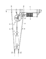
このようなヨークを用いて具体的にどのように電柱間でトロリ線等を吊架するのかにつき図1を参照しつつ説明する。図1は、トロリ線、吊架線、補助吊架線にテンションをかけるための電柱部における構造を示すものである。図1の(a)は当該構造を上面からみた要部概略図、また(b)は当該構造を側面から見た図である。 A specific description will be given of how to suspend a trolley wire or the like between utility poles using such a yoke with reference to FIG. FIG. 1 shows a structure of a power pole portion for applying tension to a trolley wire, a suspension wire, and an auxiliary suspension wire. (A) of FIG. 1 is the principal part schematic which looked at the said structure from the upper surface, and (b) is the figure which looked at the said structure from the side.
トロリ線3は、電車のパンタグラフに接触し電車に給電を行う線であり、このトロリ線3は、吊架線1及び補助吊架線2により吊架されている。トロリ線3及び補助吊架線2は、ワイヤーターンバックル101を介して第1ヨーク5の一方側のそれぞれの端に接続されている。第1ヨーク5の他方側には引き留め金具102を介して渡し線4が接続されている。この渡し線4は、第2ヨーク6の一方側の一端に引き留め金具102を介して接続されている。第2ヨーク6の一方側の別の端には、吊架線1がワイヤーターンバックル101を介して接続されている。なお、本命最初では、渡し線4も含めて吊架線類と呼ぶこととする。
The trolley line 3 is a line that contacts the pantograph of the train and supplies power to the train. The trolley line 3 is suspended by the suspension line 1 and the auxiliary suspension line 2. The trolley wire 3 and the auxiliary suspension wire 2 are connected to respective ends on one side of the
第2ヨーク6の他方側はUクレビス103を介して第3ヨーク7の一方側に連結されている。第3ヨーク7の他方側には、2列の懸垂碍子9が、連結金具106、107を介しつつ複数個接続されている。2列の懸垂碍子9のもう一方側は、第4ヨーク10の一方側両端にそれぞれ接続される。第4ヨーク10の他方側は、連結金具108を介して、第5ヨーク11の一方側に接続される。第5ヨーク11の他方側の両端はワイヤ110が接続されており、このワイヤ110には滑車13を介して、もう一端におもり14が吊り下げられた状態となっている。以上の構成によって、吊架線1、補助吊架線2、トロリ線3それぞれにテンションがかけられる仕組みとなっている。
The other side of the second yoke 6 is connected to one side of the third yoke 7 via a
ところで、電車の営業運転速度を上げるような変更を行う場合には、トロリ線、吊架線、補助吊架線を張り替える必要が生じることがある。この際、今まで用いてきたトロリ線、吊架線、補助吊架線それぞれを、異なる張力のものに変更するような場合には、トロリ線、吊架線、補助吊架線を直接的に引き留めているヨークである第1ヨーク5、第2ヨーク6の引き留めバランスが変更されることとなるので、トロリ線、吊架線、補助吊架線の張り替えと併せて第1ヨーク5、第2ヨーク6の交換も行う必要が生じる。
By the way, when making a change to increase the commercial operation speed of the train, it may be necessary to replace the trolley line, the suspension line, and the auxiliary suspension line. At this time, when changing the trolley wire, suspension wire, and auxiliary suspension wire used so far to those of different tensions, the yoke that directly holds the trolley wire, suspension wire, and auxiliary suspension wire Since the holding balance of the
従来の第1の第2ヨークの交換方法につき、図2を参照しつつ説明する。図2は、トロリ線、吊架線、補助吊架線を交換する際の様子を側面から見た図である。なお、図1中と同一部材については参照符号の記載を省略しているものもある。第2ヨークの交換方法には、まず、吊架線1及び渡し線4を、ワイヤ15及びワイヤ16でつる作業を行う。ワイヤ15の一端を電柱12にくくりつけ、もう一端を吊架線1に固着金具105で取り付けると共に、ワイヤ15の途中には張線器18を挿入する。同様にして、ワイヤ16の一端も電柱12にくくりつけ、もう一端を渡し線4に固着金具105で取り付けると共に、ワイヤ16の途中には張線器18を挿入する。この状態とした上で、張線器18でワイヤ15及びワイヤ16を徐々に巻き上げていき、吊架線1及び渡し線4の張力をワイヤ15及びワイヤ16で支えるまでにする。次に、ワイヤ17の一端をおもり14を支持するフレームにくくり、もう一端をおもりに取り付ける。ワイヤ17の間には張線器19を介挿しておき、張線器19でワイヤ17巻き上げて、おもりの重さがワイヤ110を介して第2ヨーク6に伝わらない状態とする。この状態にしておいて第2ヨーク6を交換する作業を行う。
A conventional method for replacing the first second yoke will be described with reference to FIG. FIG. 2 is a side view of a state where the trolley line, the suspension line, and the auxiliary suspension line are replaced. Note that the reference numerals of the same members as those in FIG. 1 are omitted. In the replacement method of the second yoke, first, the work of hanging the suspension wire 1 and the connecting wire 4 with the
次に従来の第2の第2ヨークの交換方法につき、図3を参照しつつ説明する。図3は、トロリ線、吊架線、補助吊架線を交換する際の様子を示す図である。図3の(a)は交換の様子を上面からみた要部概略図、また(b)は交換の様子を側面から見た図である。なお、図1中と同一部材については参照符号の記載を省略しているものもある。第2のヨーク交換方法においては、第3ヨーク7に設けられている作業用穴8を利用して、吊架線1及び渡し線4のテンションを第3ヨーク7でつるようにする。作業としては、まず、ワイヤ20の一端を第3ヨーク7の一つの作業穴8に取り付け、もう一端を吊架線1に固着金具105で取り付けると共に、ワイヤ20の途中には張線器22を挿入する。同様にして、ワイヤ21の一端も第3ヨーク7の一つの作業穴8に取り付け、もう一端を渡し線4に固着金具105で取り付けると共に、ワイヤ21の途中には張線器22を挿入する。次に、張線器22及び張線器22でワイヤ20及びワイヤ21をそれぞれ巻き上げていき、吊架線1及び渡し線4のテンションを第3ヨーク7で支える。この状態にしておいて第2ヨーク6を交換する作業を行う。
Next, a conventional method for replacing the second second yoke will be described with reference to FIG. FIG. 3 is a diagram illustrating a state in which the trolley line, the suspension line, and the auxiliary suspension line are replaced. FIG. 3A is a schematic view of the main part of the state of replacement as viewed from above, and FIG. 3B is a view of the state of replacement as viewed from the side. Note that the reference numerals of the same members as those in FIG. 1 are omitted. In the second yoke replacement method, the tension of the suspension wire 1 and the connecting wire 4 is connected by the third yoke 7 using the
従来の第1の第2ヨークの交換方法では、張線器19でワイヤ17巻き上げておもりをワイヤ17でつった状態とすると、懸垂碍子9の重さが第2ヨーク6にかかることになる。従って、第2ヨーク6を交換する作業は、懸垂碍子9を支えつつ行わなければならない。懸垂碍子9を支えての作業は、多くの作業要員や作業時間を費やすこととなり作業効率が悪い、という問題があった。一方、従来の第2の第2ヨークの交換方法では、垂直に配置されている吊架線1及び渡し線4を、水平に配置されている第3ヨーク7の2つの作業穴で支持する状態となるため、吊架線1及び渡し線4はねじれた状態となる。このような状態となると、作業要員にとって作業は非常にやりづらく、この方法でも、複雑な作業となり多大な作業時間を要してしまう、という問題がある。
In the conventional method for exchanging the first second yoke, if the
このような課題を解決するために、請求項1に係る発明は、電車のパンタグラフに給電するトロリ線及び該トロリ線を吊架する吊架線類を直接的に引き留めるヨークを取り替えるヨーク取替方法において、該ヨークを支持する2つの別のヨークの作業用穴を利用して、それぞれの別のヨークに第1取替用工具、第2取替用工具を取り付ける工程と、該第1取替用工具と、該トロリ線及び該吊架線類との間に第1ワイヤを張る工程と、該第1取替用工具と該第2取替用工具との間に第2ワイヤを張る工程と、該第1ワイヤを巻き取ることにより該ヨークの荷重を該第1ワイヤで負担させる工程と、該第2ワイヤを巻き取ることにより該第1取替用工具の荷重を該第2取替用工具でも負担させる工程と、該ヨークを交換する工程と、該第1ワイヤの荷重を再び、該ヨークで負担させ、該第1ワイヤ、該第2ワイヤ、該第1取替用工具、該第2取替用工具を取り外す工程と、からなることを特徴とする。 In order to solve such a problem, the invention according to claim 1 is a yoke replacement method for replacing a trolley wire that feeds power to a pantograph of a train and a yoke that directly holds a suspension line that suspends the trolley wire. Attaching the first replacement tool and the second replacement tool to each of the different yokes using the working holes of the two other yokes supporting the yoke, and the first replacement Stretching a first wire between the tool and the trolley wire and the suspension wires; stretching a second wire between the first replacement tool and the second replacement tool; A step of bearing the load of the yoke on the first wire by winding the first wire; and a load of the first replacement tool by winding the second wire. However, the process of burdening, the process of replacing the yoke, and the load of the first wire And the step of detaching the first wire, the second wire, the first replacement tool, and the second replacement tool, which is borne by the yoke.
また、請求項2に係る発明は、電車のパンタグラフに給電するトロリ線及び該トロリ線を吊架する吊架線類を直接的に引き留めるヨークを取り替えるためのヨーク取替用工具において、
該ヨークを支持する別のヨークの作業用穴と重なるボルト穴を有するベースプレート部と、
該ベースプレート部の中心付近から、該ベースプレート部に垂直に延設された延設部と、
該延設部に設けられた作業用穴と、からなることを特徴とする。
Further, the invention according to claim 2 is a yoke replacement tool for replacing a trolley wire that feeds power to a pantograph of a train and a yoke that directly holds a suspension line that suspends the trolley wire.
A base plate portion having a bolt hole overlapping with a working hole of another yoke supporting the yoke;
An extension portion extending perpendicularly to the base plate portion from the vicinity of the center of the base plate portion;
And a working hole provided in the extending portion.
本発明のヨーク取替用工具を用い、本発明の方法でヨークを取り替えると、ヨークにかかる荷重はほとんどない状態でヨークを交換することができる。したがって、従来のように、ヨークに懸垂碍子の荷重がかかっていたり、ヨークがねじれてしまったり、ということがないので、ヨークの取替作業を、従来より少ない作業員、短い時間で行うことができる。 If the yoke is replaced by the method of the present invention using the yoke replacement tool of the present invention, the yoke can be replaced with almost no load applied to the yoke. Therefore, unlike the conventional case, there is no load of the suspension lever on the yoke or the yoke is twisted, so that the replacement work of the yoke can be performed in a shorter time and with fewer workers than in the past. it can.
以下、本発明の実施の形態を図面を参照しつつ説明する。図4及び図5は、本発明の実施の形態に係るヨーク取替用工具の外観の斜視図である。図4の第1取替用工具30は、金属製であり、2つのボルト穴32を有するベースプレート部31、ベースプレート部31の中央部分から延設された延設部35、延設部35に設けられた作業用穴33及び34、ベースプレート部31と延設部35との間を補強する補強部36からそれぞれ構成されている。ボルト37、ナット38を取り外すことによって、ベースプレート部31間の間隙にヨークを受け入れることができるようになっており、ヨークをベースプレート部31間の間隙に受け入れた際には、ヨークの作業用穴とベースプレート部31のボルト穴32の位置が一致するようになっている。
Hereinafter, embodiments of the present invention will be described with reference to the drawings. 4 and 5 are perspective views of the appearance of the yoke replacement tool according to the embodiment of the present invention. The
図5の第2取替用工具40も第1取替用工具30とほぼ同様の構成であり、図5の第2取替用工具40は、2つのボルト穴42を有するベースプレート部41、ベースプレート部41の中央部分から延設された延設部45、延設部45に設けられた作業用穴43及び44、ベースプレート部41と延設部45との間を補強する補強部46からそれぞれ成る。ボルト47、ナット48を取り外すことによって、ベースプレート部41間の間隙にヨークを受け入れることができるようになっており、ヨークをベースプレート部41間の間隙に受け入れた際には、ヨークの作業用穴とベースプレート部41のボルト穴42の位置が一致するようになっている。
The
次に、第1取替用工具30及び第2取替用工具40を用いてどのようにヨークの交換作業を行うかにつき図6を参照しつつ説明する。図6は、本発明の実施の形態に係るヨーク取替用工具を用いてのヨーク取替方法を説明するための図である。図1の(a)はヨーク取替の様子を上面からみた要部概略図、また(b)はヨーク取替の様子を側面から見た図である。図1中と同一部材については参照符号の記載を省略しているものもある。
Next, how the yoke replacement operation is performed using the
本発明の実施の形態に係るヨーク取替用工具を用いてのヨーク取替方法で第2ヨーク6を交換する際には、概略以下のような作業手順となる。(1)第1取替用工具30及び第2取替用工具40の取り付け、(2)第1取替用工具30及び第2取替用工具40にて吊架線1及び渡し線4のテンションを負担し、(3)第2ヨーク6の交換作業、(4)第1取替用工具30及び第2取替用工具40の取り外し、という作業の流れとなる。以下、順々に説明する。
When the second yoke 6 is replaced by the yoke replacement method using the yoke replacement tool according to the embodiment of the present invention, the operation procedure is roughly as follows. (1) Attaching the
まず、第1取替用工具30及び第2取替用工具40を、それぞれ第3ヨーク7及び第5ヨーク11に取り付ける作業を行う。図4に示される第1取替用工具30のボルト37及びナット38を取り外し、ベースプレート部31間の間隙に第3ヨーク7を受け入れ、ベースプレート部31のボルト穴32と第3ヨーク7の作業用穴8との位置合わせを行い、合わせた穴にボルト37を通しナット38で締め付ける。
First, an operation of attaching the
同様にして、図5に示される第2取替用工具40のボルト47及びナット48を取り外しベースプレート部41間の間隙に第3ヨーク7を受け入れ、ベースプレート部41のボルト穴42とヨーク11の作業用穴8との位置合わせを行い、合わせた穴にボルト47を通しナット48で締め付ける。
Similarly, the
次に、ワイヤ50の一端を第1取替用工具30の作業用穴34を利用して第1取替用工具30に固定し、もう一端を吊架線1に固着金具105で取り付けると共に、ワイヤ50の途中に張線器53を挿入する。同様にして、ワイヤ51の一端も第1取替用工具30の作業用穴34を利用して第1取替用工具30に固定し、もう一端を渡し線4に固着金具105で取り付けると共に、ワイヤ51の途中には張線器53を挿入する。
Next, one end of the
次に、第1取替用工具30と第2取替用工具40とを連結する。ワイヤ54の一端を第1取替用工具30の作業用穴33を利用して第1取替用工具30に固定し、もう一端を第2取替用工具40の作業用穴44を利用して第2取替用工具40に固定すると共に、ワイヤ54の途中に張線器56を挿入する。同様にして、ワイヤ55の一端を第1取替用工具30の作業用穴33を利用して第1取替用工具30に固定し、もう一端を第2取替用工具40の作業用穴44を利用して第2取替用工具40に固定すると共に、ワイヤ55の途中に張線器56を挿入する。
Next, the
この状態とした上で、張線器53でワイヤ50及びワイヤ51を徐々に巻き上げていき、吊架線1及び渡し線4の張力を、第1取替用工具30で支えるまでにする。さらに、張線器56でワイヤ54及びワイヤ55を徐々に巻き上げていき、第1取替用工具30にかかる吊架線1及び渡し線4の張力を、第2取替用工具40でも負担するようにして支える。なお、第2取替用工具40は、あくまでバックアップ的に第1取替用工具30にかかる荷重を支える役割を果たすものであり、必ずしも必須の構成要件ではない。
In this state, the
以上のような一連の作業工程を経た上で、古い第2ヨーク6から新しい第2ヨーク6に交換し、再び張線器53及び張線器56を緩め、再び、吊架線1及び渡し線4にテンションをかけるようにしてから、第1取替用工具30、第2取替用工具40、ワイヤ50、ワイヤ51、張線器53、ワイヤ54、ワイヤ56、張線器56を取り外す。本発明のヨーク取替用工具を用い、本発明の方法で第2ヨーク6を取り替えると、第2ヨーク6にかかる荷重はほとんどない状態で第2ヨーク6を交換することができる。従来のように、第2ヨーク6に懸垂碍子9の荷重がかかっていたり、第2ヨーク6がねじれてしまったり、ということがないので、第2ヨーク6の取替作業を、従来より少ない作業員、短い時間で行うことができる。
After passing through a series of work steps as described above, the old second yoke 6 is replaced with the new second yoke 6, the
1・・・吊架線、2・・・補助吊架線、3・・・トロリ線、4・・・渡し線、5・・・第1ヨーク、6・・・第2ヨーク、7・・・第3ヨーク、8・・・作業用穴、9・・・懸垂碍子、10・・・第4ヨーク、11・・・第5ヨーク、12・・・電柱、13・・・滑車、14・・・おもり、15、16、17・・・ワイヤ、18、19・・・張線器、20、21・・・ワイヤ、22・・・張線器、30・・・第1取替用工具、31・・・ベースプレート部、32・・・ボルト穴、33、34・・・作業用穴、35・・・延設部、36・・・補強部、37・・・ボルト、38・・・ナット、40・・・第2取替用工具、41・・・ベースプレート部、42・・・ボルト穴、43、44・・・作業用穴、45・・・延設部、46・・・補強部、47・・・ボルト、48・・・ナット、50、51・・・ワイヤ、53・・・張線器、54、55・・・ワイヤ、56・・・張線器、101・・・ワイヤーターンバックル、102・・・引き留め金具、103・・・Uクレビス、105・・・固着金具、106、107、108・・・連結金具、110・・・ワイヤ
DESCRIPTION OF SYMBOLS 1 ... Suspension line, 2 ... Auxiliary suspension line, 3 ... Trolley line, 4 ... Transfer line, 5 ... 1st yoke, 6 ... 2nd yoke, 7 ... 1st 3 yoke, 8 ... work hole, 9 ... suspension lever, 10 ... fourth yoke, 11 ... fifth yoke, 12 ... utility pole, 13 ... pulley, 14 ... Weight, 15, 16, 17 ... wire, 18, 19 ... wire tensioner, 20, 21 ... wire, 22 ... wire tensioner, 30 ... first replacement tool, 31 ... Base plate part, 32 ... Bolt hole, 33, 34 ... Working hole, 35 ... Extension part, 36 ... Reinforcement part, 37 ... Bolt, 38 ... Nut, 40 ... 2nd replacement tool, 41 ... Base plate part, 42 ... Bolt hole, 43, 44 ... Work hole, 45 ... Extension part, 46 ... Reinforcement part, 4 ... Bolt, 48 ... Nut, 50, 51 ... Wire, 53 ... Tensioner, 54,55 ... Wire, 56 ... Tensioner, 101 ... Wire turnbuckle , 102 ... Clasps, 103 ... U clevis, 105 ... Fixing brackets, 106, 107, 108 ... Connecting brackets, 110 ... Wire
Claims (2)
該ヨークを支持する2つの別のヨークの作業用穴を利用して、それぞれの別のヨークに第1取替用工具、第2取替用工具を取り付ける工程と、
該第1取替用工具と、該トロリ線及び該吊架線類との間に第1ワイヤを張る工程と、
該第1取替用工具と該第2取替用工具との間に第2ワイヤを張る工程と、
該第1ワイヤを巻き取ることにより該ヨークの荷重を該第1ワイヤで負担させる工程と、
該第2ワイヤを巻き取ることにより該第1取替用工具の荷重を該第2取替用工具でも負担させる工程と、
該ヨークを交換する工程と、
該第1ワイヤの荷重を再び、該ヨークで負担させ、該第1ワイヤ、該第2ワイヤ、該第1取替用工具、該第2取替用工具を取り外す工程と、からなることを特徴とするヨーク取替方法。 In a yoke replacement method for replacing a trolley wire that feeds power to a pantograph of a train and a yoke that directly holds a trolley wire that suspends the trolley wire,
Attaching the first replacement tool and the second replacement tool to each of the other yokes using the working holes of the two other yokes supporting the yoke;
Stretching the first wire between the first replacement tool, the trolley wire and the suspension wires,
Stretching a second wire between the first replacement tool and the second replacement tool;
Bearing the load of the yoke with the first wire by winding the first wire;
The step of causing the load of the first replacement tool to be borne by the second replacement tool by winding the second wire;
Replacing the yoke;
The load of the first wire is again borne by the yoke, and the first wire, the second wire, the first replacement tool, and the second replacement tool are removed. Yoke replacement method.
該ヨークを支持する別のヨークの作業用穴と重なるボルト穴を有するベースプレート部と、
該ベースプレート部の中心付近から、該ベースプレート部に垂直に延設された延設部と、
該延設部に設けられた作業用穴と、からなることを特徴とするヨーク取替用工具。 In a yoke replacement tool for replacing a trolley wire that feeds power to a pantograph of a train and a yoke that directly holds a trolley wire that suspends the trolley wire,
A base plate portion having a bolt hole overlapping with a working hole of another yoke supporting the yoke;
An extension portion extending perpendicularly to the base plate portion from the vicinity of the center of the base plate portion;
A yoke replacement tool comprising: a working hole provided in the extending portion.
Priority Applications (1)
| Application Number | Priority Date | Filing Date | Title |
|---|---|---|---|
| JP2005320635A JP4632308B2 (en) | 2005-11-04 | 2005-11-04 | Yoke replacement method and yoke replacement tool |
Applications Claiming Priority (1)
| Application Number | Priority Date | Filing Date | Title |
|---|---|---|---|
| JP2005320635A JP4632308B2 (en) | 2005-11-04 | 2005-11-04 | Yoke replacement method and yoke replacement tool |
Publications (2)
| Publication Number | Publication Date |
|---|---|
| JP2007126013A JP2007126013A (en) | 2007-05-24 |
| JP4632308B2 true JP4632308B2 (en) | 2011-02-16 |
Family
ID=38149038
Family Applications (1)
| Application Number | Title | Priority Date | Filing Date |
|---|---|---|---|
| JP2005320635A Expired - Fee Related JP4632308B2 (en) | 2005-11-04 | 2005-11-04 | Yoke replacement method and yoke replacement tool |
Country Status (1)
| Country | Link |
|---|---|
| JP (1) | JP4632308B2 (en) |
Families Citing this family (4)
| Publication number | Priority date | Publication date | Assignee | Title |
|---|---|---|---|---|
| JP5489226B2 (en) * | 2010-07-06 | 2014-05-14 | 三和テッキ株式会社 | Relay fitting for connecting section insulator of dead section, and section insulator replacement apparatus and method used therefor |
| JP5897398B2 (en) * | 2012-04-27 | 2016-03-30 | 日本発條株式会社 | Tension balancer for overhead wires |
| JP6493965B2 (en) * | 2015-02-12 | 2019-04-03 | 日本カタン株式会社 | Tensile device replacement tool |
| CN108909533B (en) * | 2018-05-22 | 2021-08-10 | 中铁建电气化局集团第三工程有限公司 | Construction method for integrally replacing existing electrified railway contact net crossover and sectional insulator |
Citations (2)
| Publication number | Priority date | Publication date | Assignee | Title |
|---|---|---|---|---|
| JPH06144088A (en) * | 1992-11-12 | 1994-05-24 | Dengiyou:Kk | Tension measuring device for electric railcar line |
| JPH06227295A (en) * | 1993-01-29 | 1994-08-16 | East Japan Railway Co | Safety device of tension balancer |
-
2005
- 2005-11-04 JP JP2005320635A patent/JP4632308B2/en not_active Expired - Fee Related
Patent Citations (2)
| Publication number | Priority date | Publication date | Assignee | Title |
|---|---|---|---|---|
| JPH06144088A (en) * | 1992-11-12 | 1994-05-24 | Dengiyou:Kk | Tension measuring device for electric railcar line |
| JPH06227295A (en) * | 1993-01-29 | 1994-08-16 | East Japan Railway Co | Safety device of tension balancer |
Also Published As
| Publication number | Publication date |
|---|---|
| JP2007126013A (en) | 2007-05-24 |
Similar Documents
| Publication | Publication Date | Title |
|---|---|---|
| JP3996624B1 (en) | How to replace Choshiren | |
| JP4632308B2 (en) | Yoke replacement method and yoke replacement tool | |
| JP2013249678A (en) | Replacement method of oblique cable and temporary hanger for replacing oblique cable | |
| JP4861398B2 (en) | Overhead wire tension balancer and overhead wire tension balancer installation assist device | |
| JP5855523B2 (en) | 4 conductor transmission line insulator device replacement method and replacement device used for the method | |
| JP2012244644A (en) | Insulator replacement method for insulator chain | |
| JP5730674B2 (en) | Steel tower maintenance work | |
| CN107020475A (en) | A kind of crosshead sheave bracket welding equipment | |
| JP2005333789A (en) | Construction method of hanging sheave type line shifting by forming net | |
| CN107947015B (en) | Live replacement device for tension rod | |
| JP5427657B2 (en) | Tensile force release device and tension release method | |
| JP2598948B2 (en) | Tensile equipment replacement method and multi-conductor fixing bracket | |
| CN201095587Y (en) | Steel cable gripping head exchanging rack | |
| CN217458424U (en) | Hoisting frame for mechanical equipment | |
| JP4934410B2 (en) | Tightening method and chamares fitting used therefor | |
| JPS5854819Y2 (en) | Separators for utility pole reconstruction and new installation | |
| CN1027248C (en) | Method and apparatus for repairing girder bending-down of bridge crane | |
| CN218363008U (en) | Auxiliary tool for hoisting and overturning after single-side welding of floor of high-speed motor train unit | |
| JP2008125209A (en) | Wire tightening method and vernier metal for use therein | |
| KR200262304Y1 (en) | A tool for using changing insulator apparatus | |
| JP4271989B2 (en) | Elevator control cable device | |
| US5887019A (en) | Methods and apparatus for securing induction coils within an induction coil module | |
| CN214512332U (en) | Tensioning tool | |
| CN208452829U (en) | A kind of contact nets in electrified railways wire clamp and positioning device | |
| JP3068910U (en) | Replacement tool for insulator linkage device |
Legal Events
| Date | Code | Title | Description |
|---|---|---|---|
| A621 | Written request for application examination |
Free format text: JAPANESE INTERMEDIATE CODE: A621 Effective date: 20080115 |
|
| A131 | Notification of reasons for refusal |
Free format text: JAPANESE INTERMEDIATE CODE: A131 Effective date: 20100922 |
|
| A521 | Request for written amendment filed |
Free format text: JAPANESE INTERMEDIATE CODE: A523 Effective date: 20101005 |
|
| TRDD | Decision of grant or rejection written | ||
| A01 | Written decision to grant a patent or to grant a registration (utility model) |
Free format text: JAPANESE INTERMEDIATE CODE: A01 Effective date: 20101110 |
|
| A01 | Written decision to grant a patent or to grant a registration (utility model) |
Free format text: JAPANESE INTERMEDIATE CODE: A01 |
|
| A61 | First payment of annual fees (during grant procedure) |
Free format text: JAPANESE INTERMEDIATE CODE: A61 Effective date: 20101111 |
|
| R150 | Certificate of patent or registration of utility model |
Free format text: JAPANESE INTERMEDIATE CODE: R150 |
|
| FPAY | Renewal fee payment (event date is renewal date of database) |
Free format text: PAYMENT UNTIL: 20131126 Year of fee payment: 3 |
|
| R250 | Receipt of annual fees |
Free format text: JAPANESE INTERMEDIATE CODE: R250 |
|
| R250 | Receipt of annual fees |
Free format text: JAPANESE INTERMEDIATE CODE: R250 |
|
| R250 | Receipt of annual fees |
Free format text: JAPANESE INTERMEDIATE CODE: R250 |
|
| R250 | Receipt of annual fees |
Free format text: JAPANESE INTERMEDIATE CODE: R250 |
|
| R250 | Receipt of annual fees |
Free format text: JAPANESE INTERMEDIATE CODE: R250 |
|
| LAPS | Cancellation because of no payment of annual fees |