JP4630777B2 - Method, apparatus, computer program and storage medium for changing digital document - Google Patents
Method, apparatus, computer program and storage medium for changing digital document Download PDFInfo
- Publication number
- JP4630777B2 JP4630777B2 JP2005265895A JP2005265895A JP4630777B2 JP 4630777 B2 JP4630777 B2 JP 4630777B2 JP 2005265895 A JP2005265895 A JP 2005265895A JP 2005265895 A JP2005265895 A JP 2005265895A JP 4630777 B2 JP4630777 B2 JP 4630777B2
- Authority
- JP
- Japan
- Prior art keywords
- color digital
- digital image
- color
- image
- document
- Prior art date
- Legal status (The legal status is an assumption and is not a legal conclusion. Google has not performed a legal analysis and makes no representation as to the accuracy of the status listed.)
- Expired - Fee Related
Links
Images


Classifications
-
- H—ELECTRICITY
- H04—ELECTRIC COMMUNICATION TECHNIQUE
- H04N—PICTORIAL COMMUNICATION, e.g. TELEVISION
- H04N1/00—Scanning, transmission or reproduction of documents or the like, e.g. facsimile transmission; Details thereof
- H04N1/387—Composing, repositioning or otherwise geometrically modifying originals
-
- G—PHYSICS
- G06—COMPUTING; CALCULATING OR COUNTING
- G06F—ELECTRIC DIGITAL DATA PROCESSING
- G06F40/00—Handling natural language data
- G06F40/10—Text processing
- G06F40/166—Editing, e.g. inserting or deleting
- G06F40/169—Annotation, e.g. comment data or footnotes
-
- G—PHYSICS
- G06—COMPUTING; CALCULATING OR COUNTING
- G06T—IMAGE DATA PROCESSING OR GENERATION, IN GENERAL
- G06T7/00—Image analysis
- G06T7/30—Determination of transform parameters for the alignment of images, i.e. image registration
- G06T7/37—Determination of transform parameters for the alignment of images, i.e. image registration using transform domain methods
-
- H—ELECTRICITY
- H04—ELECTRIC COMMUNICATION TECHNIQUE
- H04N—PICTORIAL COMMUNICATION, e.g. TELEVISION
- H04N1/00—Scanning, transmission or reproduction of documents or the like, e.g. facsimile transmission; Details thereof
- H04N1/0035—User-machine interface; Control console
- H04N1/00352—Input means
- H04N1/00355—Mark-sheet input
- H04N1/00358—Type of the scanned marks
-
- H—ELECTRICITY
- H04—ELECTRIC COMMUNICATION TECHNIQUE
- H04N—PICTORIAL COMMUNICATION, e.g. TELEVISION
- H04N1/00—Scanning, transmission or reproduction of documents or the like, e.g. facsimile transmission; Details thereof
- H04N1/0035—User-machine interface; Control console
- H04N1/00352—Input means
- H04N1/00355—Mark-sheet input
- H04N1/00368—Location of the scanned marks
- H04N1/00374—Location of the scanned marks on the same page as at least a part of the image
-
- H—ELECTRICITY
- H04—ELECTRIC COMMUNICATION TECHNIQUE
- H04N—PICTORIAL COMMUNICATION, e.g. TELEVISION
- H04N1/00—Scanning, transmission or reproduction of documents or the like, e.g. facsimile transmission; Details thereof
- H04N1/0035—User-machine interface; Control console
- H04N1/00352—Input means
- H04N1/00355—Mark-sheet input
- H04N1/00376—Means for identifying a mark sheet or area
-
- H—ELECTRICITY
- H04—ELECTRIC COMMUNICATION TECHNIQUE
- H04N—PICTORIAL COMMUNICATION, e.g. TELEVISION
- H04N1/00—Scanning, transmission or reproduction of documents or the like, e.g. facsimile transmission; Details thereof
- H04N1/00962—Input arrangements for operating instructions or parameters, e.g. updating internal software
- H04N1/00968—Input arrangements for operating instructions or parameters, e.g. updating internal software by scanning marks on a sheet
-
- H—ELECTRICITY
- H04—ELECTRIC COMMUNICATION TECHNIQUE
- H04N—PICTORIAL COMMUNICATION, e.g. TELEVISION
- H04N1/00—Scanning, transmission or reproduction of documents or the like, e.g. facsimile transmission; Details thereof
- H04N1/32—Circuits or arrangements for control or supervision between transmitter and receiver or between image input and image output device, e.g. between a still-image camera and its memory or between a still-image camera and a printer device
- H04N1/32101—Display, printing, storage or transmission of additional information, e.g. ID code, date and time or title
- H04N1/32128—Display, printing, storage or transmission of additional information, e.g. ID code, date and time or title attached to the image data, e.g. file header, transmitted message header, information on the same page or in the same computer file as the image
- H04N1/32133—Display, printing, storage or transmission of additional information, e.g. ID code, date and time or title attached to the image data, e.g. file header, transmitted message header, information on the same page or in the same computer file as the image on the same paper sheet, e.g. a facsimile page header
-
- G—PHYSICS
- G06—COMPUTING; CALCULATING OR COUNTING
- G06T—IMAGE DATA PROCESSING OR GENERATION, IN GENERAL
- G06T2207/00—Indexing scheme for image analysis or image enhancement
- G06T2207/10—Image acquisition modality
- G06T2207/10024—Color image
-
- G—PHYSICS
- G06—COMPUTING; CALCULATING OR COUNTING
- G06T—IMAGE DATA PROCESSING OR GENERATION, IN GENERAL
- G06T2207/00—Indexing scheme for image analysis or image enhancement
- G06T2207/20—Special algorithmic details
- G06T2207/20048—Transform domain processing
- G06T2207/20056—Discrete and fast Fourier transform, [DFT, FFT]
-
- G—PHYSICS
- G06—COMPUTING; CALCULATING OR COUNTING
- G06T—IMAGE DATA PROCESSING OR GENERATION, IN GENERAL
- G06T2207/00—Indexing scheme for image analysis or image enhancement
- G06T2207/30—Subject of image; Context of image processing
- G06T2207/30108—Industrial image inspection
- G06T2207/30144—Printing quality
-
- H—ELECTRICITY
- H04—ELECTRIC COMMUNICATION TECHNIQUE
- H04N—PICTORIAL COMMUNICATION, e.g. TELEVISION
- H04N2201/00—Indexing scheme relating to scanning, transmission or reproduction of documents or the like, and to details thereof
- H04N2201/32—Circuits or arrangements for control or supervision between transmitter and receiver or between image input and image output device, e.g. between a still-image camera and its memory or between a still-image camera and a printer device
- H04N2201/3201—Display, printing, storage or transmission of additional information, e.g. ID code, date and time or title
- H04N2201/3225—Display, printing, storage or transmission of additional information, e.g. ID code, date and time or title of data relating to an image, a page or a document
- H04N2201/3242—Display, printing, storage or transmission of additional information, e.g. ID code, date and time or title of data relating to an image, a page or a document of processing required or performed, e.g. for reproduction or before recording
-
- H—ELECTRICITY
- H04—ELECTRIC COMMUNICATION TECHNIQUE
- H04N—PICTORIAL COMMUNICATION, e.g. TELEVISION
- H04N2201/00—Indexing scheme relating to scanning, transmission or reproduction of documents or the like, and to details thereof
- H04N2201/32—Circuits or arrangements for control or supervision between transmitter and receiver or between image input and image output device, e.g. between a still-image camera and its memory or between a still-image camera and a printer device
- H04N2201/3201—Display, printing, storage or transmission of additional information, e.g. ID code, date and time or title
- H04N2201/3225—Display, printing, storage or transmission of additional information, e.g. ID code, date and time or title of data relating to an image, a page or a document
- H04N2201/3245—Display, printing, storage or transmission of additional information, e.g. ID code, date and time or title of data relating to an image, a page or a document of image modifying data, e.g. handwritten addenda, highlights or augmented reality information
Landscapes
- Engineering & Computer Science (AREA)
- Multimedia (AREA)
- Signal Processing (AREA)
- Computer Vision & Pattern Recognition (AREA)
- Theoretical Computer Science (AREA)
- General Engineering & Computer Science (AREA)
- General Physics & Mathematics (AREA)
- Physics & Mathematics (AREA)
- Health & Medical Sciences (AREA)
- Artificial Intelligence (AREA)
- Audiology, Speech & Language Pathology (AREA)
- Computational Linguistics (AREA)
- General Health & Medical Sciences (AREA)
- Editing Of Facsimile Originals (AREA)
- Facsimile Image Signal Circuits (AREA)
- Color Image Communication Systems (AREA)
- Image Processing (AREA)
Description
本発明は、一般に、ワードプロセシングに関し、特に、デジタル文書を変更する方法及び装置に関する。更に、本発明は、デジタル文書を変更するためのコンピュータプログラムが記録されたコンピュータ可読媒体を含むコンピュータプログラム製品に関する。 The present invention relates generally to word processing, and more particularly to a method and apparatus for modifying a digital document. The invention further relates to a computer program product comprising a computer readable medium having recorded thereon a computer program for modifying a digital document.
最新の文書編集ソフトウェアの出現に伴い、「ペーパーレスオフィス」が予測されるにも関らず、デジタル文書を紙面に印刷したコピー(すなわち、「ハードコピー」)を読み、改訂することを好む人々は、依然として多い。ハードコピーを好むのは、主に、デジタル文書のハードコピーを使用する方が、ナビゲーションが容易であり、変更(例えば、補正及び/又は注釈付け)が容易であり、且つ情報密度がより高いという理由による。 With the advent of modern document editing software, people who prefer to read and revise a copy of a digital document printed on paper (ie, a “hard copy”) despite the anticipated “paperless office” Still many. I prefer hardcopy mainly because it is easier to navigate, amend (e.g., correct and / or annotate), and have higher information density when using a hardcopy of a digital document. Depending on the reason.
大容量のデジタル文書原稿を作成する場合、デジタル文書の作成者は、その文書を何度か印刷し、改訂するであろう。改訂は、その都度、文書のハードコピーを通読し、例えば、蛍光ペン、ペン又は鉛筆を使用して、文書のハードコピーを変更することを含む。そのような変更処理が完了すると、通常、いずれかの人に、ハードコピー上にマークされた変更を文書のデジタルコピーに組み込む責任が割り当てられる。このような従来の原稿作成処理は、文書のハードコピーの改訂がどの関係者によっても実行可能であるという利点を有する。また、従来の起草処理によれば、文書の内容に対して、都合の良い任意の形態の変更を実行できる。更に、文書のハードコピーの改訂が、改訂担当者に都合の良い任意の場所で行われてもよい。 When creating a large volume digital document manuscript, the creator of the digital document will print and revise the document several times. Each revision involves reading through a hard copy of the document and changing the hard copy of the document using, for example, a highlighter, pen or pencil. When such a change process is complete, usually someone is assigned the responsibility to incorporate the changes marked on the hardcopy into the digital copy of the document. Such a conventional manuscript preparation process has the advantage that revision of a hard copy of a document can be performed by any party. Further, according to the conventional drafting process, any convenient form of change can be performed on the content of the document. Furthermore, revisions of the hard copy of the document may be made at any convenient location for the revision personnel.
しかし、以上説明したようなデジタル文書の変更には、問題点もある。例えば、文書の変更済(例えば、補正済及び/又は注釈付き)ハードコピーと、コンピュータの表示画面等に表示される文書のデジタルコピーとが、物理的に分離されるため、変更の速度が遅くなる。文書の2つのコピーの間を頻繁に行き来することにより、文書を変更中の作成者が、文書の2つのコピーのうちの一方で前後関係を失い、正しい場所を再び探し出さなければならなくなる場合が多くなる。文書に対して大幅な変更が実行され、文書のデジタルコピーにおけるテキストの場所が数ページも動く場合、この問題は、更に深刻になる。更に、文書のデジタルコピーに変更を組み込む時にも、注釈又は補正が見落とされるか(すなわち、ハードコピー上で気付かない場合)、あるいは後回しにしたまま忘れられしまうことも起こりがちである。 However, there are problems with the change of the digital document as described above. For example, a modified (e.g., corrected and / or annotated) hard copy of a document and a digital copy of the document displayed on a computer display screen or the like are physically separated, resulting in a slow modification speed. Become. Frequent navigation between two copies of a document causes the author who is modifying the document to lose context in one of the two copies of the document and have to find the correct location again Will increase. This problem is exacerbated when significant changes are made to the document and the text location in the digital copy of the document moves several pages. In addition, when incorporating changes into a digital copy of a document, annotations or corrections are often overlooked (ie, not noticed on the hard copy) or forgotten to be left behind.
デジタル文書を変更するという問題に対応するいくつかの方法が知られている。1つの方法は、ユーザが文書のハードコピーを変更する時、ユーザのペンの動きを捕捉するために、デジタルタブレット装置又は他の何らかの類似の装置を使用する。ペンの動きに応答して、そのペンの動きに対応する変更が、デジタル文書に直接入力される。周知の別の方法は、可搬性を与え、ペンの動きを捕捉するために、タブレット型パーソナルコンピュータを使用するが、この場合にも、デジタル文書を直接変更する。 Several methods are known to address the problem of changing digital documents. One method uses a digital tablet device or some other similar device to capture the movement of the user's pen when the user changes the hard copy of the document. In response to the pen movement, changes corresponding to the pen movement are entered directly into the digital document. Another known method uses a tablet personal computer to provide portability and capture pen movement, but again, the digital document is modified directly.
文書を変更する他の周知の方法は、特殊な「デジタルペン」装置を使用し、デジタルペンの動きを記録するために、特殊マーキングが施された紙を使用する。文書に対して実行された変更は、後に、文書のデジタルコピーにインポートされ、デジタルコピーと位置合わせされてもよい。 Another well-known method of modifying a document uses a special “digital pen” device and uses paper with special markings to record the movement of the digital pen. Changes made to the document may later be imported into a digital copy of the document and aligned with the digital copy.
上述の方法の多くは、一般のユーザにはすぐに入手できない特殊な機器を必要とするという欠点を有する。上述の方法の中には、ぺンとハードコピーとを利用する従来の変更方法では可能であった自由な場所の移動ができない方法もある。また、文書の各ページが識別され、デジタル化装置に対して文書の場所が確定される場合、特殊加工紙を使用する方法では、通常、ユーザは、そのページの開始位置で、「校正」ステップを実行する必要がある。 Many of the methods described above have the disadvantage of requiring special equipment that is not readily available to the general user. Among the above-mentioned methods, there is a method in which a free place cannot be moved, which is possible with the conventional change method using pen and hard copy. Also, if each page of the document is identified and the location of the document is determined with respect to the digitizing device, the method using specially processed paper typically requires the user to perform a “proof” step at the start of the page. Need to run.
周知の文書変更方法として、特殊な機器を必要としない方法もいくつかある。それらの方法によれば、文書のハードコピーに対する変更(例えば、注釈付け又は補正)を、任意の明るい色のペンによって実行できる。変更が完了した時点で、文書のハードコピーの画像が、スキャナを使用して生成される。生成された画像を解析することにより、文書に対する変更が、色により識別されてもよい。色により変更を識別する方法は、いくつかのカラーペンに対して、又は異なる種類のマーキング(例えば、蛍光ペン、鉛筆)に対して、そのような識別が機能しないという欠点を有する。カラーイラスト及び表を含む文書に対して、そのような識別が誤って実行され、イラスト自体が変更として識別されてしまう場合もある。 There are several known document modification methods that do not require special equipment. According to these methods, changes to the hard copy of the document (eg, annotation or correction) can be performed with any light colored pen. When the change is complete, a hard copy image of the document is generated using the scanner. By analyzing the generated image, changes to the document may be identified by color. The method of identifying changes by color has the disadvantage that such identification does not work for some color pens or for different types of markings (eg highlighters, pencils). Such identification may be erroneously performed on documents containing color illustrations and tables, and the illustrations themselves may be identified as changes.
文書の変更済ハードコピーをデジタル形式に変換する周知の方法の1つは、文書を再構成する目的で、文書から複数のテキスト部分を抽出するために、光学文字認識(「OCR」)を使用する。OCRにより認識されないテキスト部分を変更として考えることができ、それらの部分は、ユーザにより検査される必要がある。しかし、OCRを使用する既存の文書変更方法は、元のデジタル文書を参照せずに、変更をデジタル形式に変換する。そのような既存の方法は、元の文書を入手できない場合には好都合である。しかし、既存のOCR方法は、改訂履歴、作成者情報、複雑なテキスト書式化規則及び組込みオブジェクト(例えば、チャート)に対するリンク等のデジタル文書と関連する補足情報(又はメタデータ)を失いやすい。また、OCR方法において、印刷及び走査により、イラスト及び図の画質も損なわれることがある。印刷と走査とが繰り返される度に、イラスト及び図の画質は劣化し続ける。 One well-known method of converting a modified hard copy of a document to digital form uses optical character recognition ("OCR") to extract multiple text portions from the document for the purpose of reconstructing the document. To do. Text portions that are not recognized by the OCR can be considered as changes, and those portions need to be examined by the user. However, existing document modification methods that use OCR convert changes to a digital format without referring to the original digital document. Such existing methods are advantageous when the original document is not available. However, existing OCR methods are prone to losing supplemental information (or metadata) associated with digital documents such as revision history, author information, complex text formatting rules and links to embedded objects (eg, charts). In the OCR method, the image quality of illustrations and drawings may be impaired by printing and scanning. Each time printing and scanning are repeated, the image quality of illustrations and drawings continues to deteriorate.
文書の変更済ハードコピーをデジタル形式に変換する周知の別の方法は、専門の校正者により使用される校正マーク、又は他の所定の記号を識別するために、文書のハードコピーの画像を処理する。そのような方法は、それらの所定の記号を熟知する少数の人々には有用であるが、多くの人々は、そのような記号に精通していない。更に、記号は、それぞれ、固定された1つの意味しか持たず、文書を変更する人は、追加変更を挿入することを望むことが多いため、そのような追加変更の一部が認識されない可能性もある。 Another well-known method of converting a modified hard copy of a document to digital form is to process the image of the document hard copy to identify proof marks or other predetermined symbols used by professional proofreaders. To do. Such methods are useful for a few people who are familiar with those predetermined symbols, but many are not familiar with such symbols. In addition, each symbol has only one fixed meaning, and those who change the document often want to insert additional changes, so some of these additional changes may not be recognized. There is also.
従って、デジタル文書を変更する改善された方法が必要とされることは明らかである。 Thus, there is clearly a need for an improved method for modifying digital documents.
上述の先行技術は、下記の文献において開示される。
本発明の目的は、既存構成の1つ以上の欠点を実質的に克服すること、又は少なくとも改善することである。 It is an object of the present invention to substantially overcome or at least ameliorate one or more disadvantages of existing configurations.
本発明の1つの面によると、カラーデジタル文書を変更する方法であって、当該方法が、
前記カラーデジタル文書を第1のカラーデジタル画像に変換するステップと、
前記カラーデジタル文書の変更済みのハードコピーをスキャンすることにより、第2のカラーデジタル画像を生成するステップと、
前記第1のカラーデジタル画像と前記第2のカラーデジタル画像とを関連付ける回転パラメータ、変倍パラメータおよび平行移動変換パラメータを求め、求められたそれぞれのパラメータを用いて、粗位置合わせされた第2のカラーデジタル画像を生成するステップと、
前記第1のカラーデジタル画像と、前記粗位置合わせされた第2のカラーデジタル画像とを比較して、前記粗位置合わせされた第2のカラーデジタル画像の画素を前記第1のカラーデジタル画像にマッピングするために必要とされる変位を示す変位マップを生成するステップと、
前記粗位置合わせされた第2のカラーデジタル画像の各画素の位置を、前記変位マップから求められる線形平行移動変換パラメータを用いて補間する値を算出して前記各画素の位置を補間する補間変位マップを生成し、前記変位マップと前記補間変位マップとを加算して求められる歪マップを生成するステップと、
前記粗位置合わせされた第2のカラーデジタル画像の画素を、前記粗位置合わせにおいて求められた前記回転パラメータ、変倍パラメータおよび平行移動変換パラメータを前記歪マップに加算して求められるワープマップを用いて、前記第1のカラーデジタル画像の画素に対応付けて、前記第1のカラーデジタル画像に対して精細位置合わせされた第2のカラーデジタル画像を生成するステップと、
前記精細位置合わせされた第2のカラーデジタル画像の色を、前記第1のカラーデジタル画像の色に、画素レベルで色合わせを行い、色合わせされた第2のカラーデジタル画像を生成するステップと、
前記カラーデジタル文書のハードコピーに対して実行された変更を判定するために、前記第1のデジタル画像を、前記色合わせされた第2のカラーデジタル画像と比較するステップと、
前記判定された変更に基づいて、前記カラーデジタル文書を変更するステップと、
を備えることを特徴とする。
According to one aspect of the invention, a method for modifying a color digital document, the method comprising:
Converting the color digital document into a first color digital image;
By scanning a hardcopy of changed the color digital document, and generating a second color digital image,
A rotation parameter, a variable magnification parameter, and a translation conversion parameter for associating the first color digital image and the second color digital image are obtained, and the second coarsely aligned second parameter is obtained using the obtained parameters. Generating a color digital image;
The first color digital image and the coarsely aligned second color digital image are compared, and the pixels of the coarsely aligned second color digital image are converted into the first color digital image. Generating a displacement map indicating the displacements required for mapping;
Interpolation displacement for interpolating the position of each pixel by calculating a value for interpolating the position of each pixel of the coarsely aligned second color digital image using a linear translation conversion parameter obtained from the displacement map Generating a map, generating a distortion map obtained by adding the displacement map and the interpolated displacement map ;
Pixels of the second color digital images the rough alignment, the coarse position the rotary obtained in registration parameters, the warp map obtained by adding the scaling parameters and translation transformation parameters to the distortion map using Generating a second color digital image finely aligned with respect to the first color digital image in association with the pixels of the first color digital image ;
Color-matching the color of the second color digital image finely aligned with the color of the first color digital image at a pixel level to generate a color-matched second color digital image; ,
Comparing the first digital image with the color-matched second color digital image to determine changes made to the hard copy of the color digital document;
Changing the color digital document based on the determined change;
It is characterized by providing.
本発明の別の側面によると、カラーデジタル文書を変更する装置であって、当該装置が、
前記カラーデジタル文書を第1のカラーデジタル画像に変換する手段と、
前記カラーデジタル文書の変更済みのハードコピーをスキャンすることにより、第2のカラーデジタル画像を生成する手段と、
前記第1のカラーデジタル画像と前記第2のカラーデジタル画像とを関連付ける回転パラメータ、変倍パラメータおよび平行移動変換パラメータを求め、求められたそれぞれのパラメータを用いて、粗位置合わせされた第2のカラーデジタル画像を生成する手段と、
前記第1のカラーデジタル画像と、前記粗位置合わせされた第2のカラーデジタル画像とを比較して、前記粗位置合わせされた第2のカラーデジタル画像の画素を前記第1のカラーデジタル画像にマッピングするために必要とされる変位を示す変位マップを生成する手段と、
前記粗位置合わせされた第2のカラーデジタル画像の各画素の位置を、前記変位マップから求められる線形平行移動変換パラメータを用いて補間する値を算出して前記各画素の位置を補間する補間変位マップを生成し、前記変位マップと前記補間変位マップとを加算して求められる歪マップを生成する手段と、
前記粗位置合わせされた第2のカラーデジタル画像の画素を、前記粗位置合わせにおいて求められた前記回転パラメータ、変倍パラメータおよび平行移動変換パラメータを前記歪マップに加算して求められるワープマップを用いて、前記第1のカラーデジタル画像の画素に対応付けて、前記第1のカラーデジタル画像に対して精細位置合わせされた第2のカラーデジタル画像を生成する手段と、
前記精細位置合わせされた第2のカラーデジタル画像の色を、前記第1のカラーデジタル画像の色に、画素レベルで色合わせを行い、色合わせされた第2のカラーデジタル画像を生成する手段と、
前記カラーデジタル文書のハードコピーに対して実行された変更を判定するために、前記第1のデジタル画像を、前記色合わせされた第2のカラーデジタル画像と比較する手段と、
前記判定された変更に基づいて、前記カラーデジタル文書を変更する手段と、
を備えることを特徴とする。
According to another aspect of the present invention, an apparatus for modifying a color digital document, the apparatus comprising:
Means for converting the color digital document into a first color digital image;
By scanning a hardcopy of changed the color digital document, and means for generating a second color digital image,
A rotation parameter, a variable magnification parameter, and a translation conversion parameter for associating the first color digital image and the second color digital image are obtained, and the second coarsely aligned second parameter is obtained using the obtained parameters. Means for generating a color digital image;
The first color digital image and the coarsely aligned second color digital image are compared, and the pixels of the coarsely aligned second color digital image are converted into the first color digital image. Means for generating a displacement map indicating the displacements required for mapping;
Interpolated displacement for interpolating the position of each pixel by calculating a value for interpolating the position of each pixel of the coarsely aligned second color digital image using a linear translation conversion parameter obtained from the displacement map Means for generating a map, and generating a distortion map obtained by adding the displacement map and the interpolated displacement map ;
Pixels of the second color digital images the rough alignment, the coarse position the rotary obtained in registration parameters, the warp map obtained by adding the scaling parameters and translation transformation parameters to the distortion map using Means for generating a second color digital image finely aligned with respect to the first color digital image in association with the pixels of the first color digital image ;
Means for color-adjusting the color of the second color digital image finely aligned with the color of the first color digital image at a pixel level to generate a color-matched second color digital image; ,
Means for comparing the first digital image with the color-matched second color digital image to determine changes made to the hard copy of the color digital document;
Means for changing the color digital document based on the determined change;
It is characterized by providing.
本発明の別の面によると、カラーデジタル文書を変更する方法をコンピュータに実行させるコンピュータプログラムであって、当該方法が、
前記カラーデジタル文書を第1のカラーデジタル画像に変換するステップと、
前記カラーデジタル文書の変更済みのハードコピーをスキャンすることにより、第2のカラーデジタル画像を生成するステップと、
前記第1のカラーデジタル画像と前記第2のカラーデジタル画像とを関連付ける回転パラメータ、変倍パラメータおよび平行移動変換パラメータを求め、求められたそれぞれのパラメータを用いて、粗位置合わせされた第2のカラーデジタル画像を生成するステップと、
前記第1のカラーデジタル画像と、前記粗位置合わせされた第2のカラーデジタル画像とを比較して、前記粗位置合わせされた第2のカラーデジタル画像の画素を前記第1のカラーデジタル画像にマッピングするために必要とされる変位を示す変位マップを生成するステップと、
前記粗位置合わせされた第2のカラーデジタル画像の各画素の位置を、前記変位マップから求められる線形平行移動変換パラメータを用いて補間する値を算出して前記各画素の位置を補間する補間変位マップを生成し、前記変位マップと前記補間変位マップとを加算して求められる歪マップを生成するステップと、
前記粗位置合わせされた第2のカラーデジタル画像の画素を、前記粗位置合わせにおいて求められた前記回転パラメータ、変倍パラメータおよび平行移動変換パラメータを前記歪マップに加算して求められるワープマップを用いて、前記第1のカラーデジタル画像の画素に対応付けて、前記第1のカラーデジタル画像に対して精細位置合わせされた第2のカラーデジタル画像を生成するステップと、
前記精細位置合わせされた第2のカラーデジタル画像の色を、前記第1のカラーデジタル画像の色に、画素レベルで色合わせを行い、色合わせされた第2のカラーデジタル画像を生成するステップと、
前記カラーデジタル文書のハードコピーに対して実行された変更を判定するために、前記第1のデジタル画像を、前記色合わせされた第2のカラーデジタル画像と比較するステップと、
前記判定された変更に基づいて、前記カラーデジタル文書を変更するステップと、
を備えることを特徴とする。
According to another aspect of the present invention, a computer program for causing a computer to execute a method for changing a color digital document, the method comprising:
Converting the color digital document into a first color digital image;
By scanning a hardcopy of changed the color digital document, and generating a second color digital image,
A rotation parameter, a variable magnification parameter, and a translation conversion parameter for associating the first color digital image and the second color digital image are obtained, and the second coarsely aligned second parameter is obtained using the obtained parameters. Generating a color digital image;
The first color digital image and the coarsely aligned second color digital image are compared, and the pixels of the coarsely aligned second color digital image are converted into the first color digital image. Generating a displacement map indicating the displacements required for mapping;
Interpolation displacement for interpolating the position of each pixel by calculating a value for interpolating the position of each pixel of the coarsely aligned second color digital image using a linear translation conversion parameter obtained from the displacement map Generating a map, generating a distortion map obtained by adding the displacement map and the interpolated displacement map ;
Pixels of the second color digital images the rough alignment, the coarse position the rotary obtained in registration parameters, the warp map obtained by adding the scaling parameters and translation transformation parameters to the distortion map using Generating a second color digital image finely aligned with respect to the first color digital image in association with the pixels of the first color digital image ;
Color-matching the color of the second color digital image finely aligned with the color of the first color digital image at a pixel level to generate a color-matched second color digital image; ,
Comparing the first digital image with the color-matched second color digital image to determine changes made to the hard copy of the color digital document;
Changing the color digital document based on the determined change;
It is characterized by providing.
本発明の別の面によると、カラーデジタル文書を変更する方法をコンピュータに実行させるコンピュータプログラムが格納されたコンピュータ可読の記憶媒体であって、当該方法が、
前記カラーデジタル文書を第1のカラーデジタル画像に変換するステップと、
前記カラーデジタル文書の変更済みのハードコピーをスキャンすることにより、第2のカラーデジタル画像を生成するステップと、
前記第1のカラーデジタル画像と前記第2のカラーデジタル画像とを関連付ける回転パラメータ、変倍パラメータおよび平行移動変換パラメータを求め、求められたそれぞれのパラメータを用いて、粗位置合わせされた第2のカラーデジタル画像を生成するステップと、
前記第1のカラーデジタル画像と、前記粗位置合わせされた第2のカラーデジタル画像とを比較して、前記粗位置合わせされた第2のカラーデジタル画像の画素を前記第1のカラーデジタル画像にマッピングするために必要とされる変位を示す変位マップを生成するステップと、
前記粗位置合わせされた第2のカラーデジタル画像の各画素の位置を、前記変位マップから求められる線形平行移動変換パラメータを用いて補間する値を算出して前記各画素の位置を補間する補間変位マップを生成し、前記変位マップと前記補間変位マップとを加算して求められる歪マップを生成するステップと、
前記粗位置合わせされた第2のカラーデジタル画像の画素を、前記粗位置合わせにおいて求められた前記回転パラメータ、変倍パラメータおよび平行移動変換パラメータを前記歪マップに加算して求められるワープマップを用いて、前記第1のカラーデジタル画像の画素に対応付けて、前記第1のカラーデジタル画像に対して精細位置合わせされた第2のカラーデジタル画像を生成するステップと、
前記精細位置合わせされた第2のカラーデジタル画像の色を、前記第1のカラーデジタル画像の色に、画素レベルで色合わせを行い、色合わせされた第2のカラーデジタル画像を生成するステップと、
前記カラーデジタル文書のハードコピーに対して実行された変更を判定するために、前記第1のデジタル画像を、前記色合わせされた第2のカラーデジタル画像と比較するステップと、
前記判定された変更に基づいて、前記カラーデジタル文書を変更するステップと、
を備えることを特徴とする。
According to another aspect of the present invention, a computer-readable storage medium storing a computer program that causes a computer to execute a method for modifying a color digital document, the method comprising:
Converting the color digital document into a first color digital image;
By scanning a hardcopy of changed the color digital document, and generating a second color digital image,
A rotation parameter, a variable magnification parameter, and a translation conversion parameter for associating the first color digital image and the second color digital image are obtained, and the second coarsely aligned second parameter is obtained using the obtained parameters. Generating a color digital image;
The first color digital image and the coarsely aligned second color digital image are compared, and the pixels of the coarsely aligned second color digital image are converted into the first color digital image. Generating a displacement map indicating the displacements required for mapping;
Interpolation displacement for interpolating the position of each pixel by calculating a value for interpolating the position of each pixel of the coarsely aligned second color digital image using a linear translation conversion parameter obtained from the displacement map Generating a map, generating a distortion map obtained by adding the displacement map and the interpolated displacement map ;
Pixels of the second color digital images the rough alignment, the coarse position the rotary obtained in registration parameters, the warp map obtained by adding the scaling parameters and translation transformation parameters to the distortion map using Generating a second color digital image finely aligned with respect to the first color digital image in association with the pixels of the first color digital image ;
Color-matching the color of the second color digital image finely aligned with the color of the first color digital image at a pixel level to generate a color-matched second color digital image; ,
Comparing the first digital image with the color-matched second color digital image to determine changes made to the hard copy of the color digital document;
Changing the color digital document based on the determined change;
It is characterized by providing.
添付の図を参照して、従来技術のいくつかの面及び本発明の1つ以上の実施形態を説明する。1つ以上の添付の図面において、ステップ及び/又は特徴を参照する場合、同一の符号を有するステップ及び/又は特徴は、説明の目的のため、指示がない限り、同一の機能又は動作を有する。 Several aspects of the prior art and one or more embodiments of the present invention will be described with reference to the accompanying drawings. When referring to steps and / or features in one or more of the accompanying drawings, steps and / or features having the same reference number have the same function or operation for the purpose of explanation, unless otherwise indicated.
尚、「背景技術」における説明、及び上述の従来技術の構成に関する説明は、各刊行物により及び/又は使用することにより周知技術を形成する文献の記述又は装置に関する。このことは、本発明者又は本出願人による表現として解釈されるべきではなく、そのような文献又は装置は、何らかの方法で、当技術の周知技術の一部を形成する。 It should be noted that the description in the “Background Art” and the above-described description of the configuration of the related art relate to a description or apparatus of a document that forms a well-known technique by using and / or using each publication. This should not be construed as an expression by the inventor or the applicant, and such documents or devices in any way form part of the well-known art of the art.
本明細書において説明される方法は、図1に示されるような汎用コンピュータシステム100を使用して実現されてもよい。図1において、図2〜図28の処理は、コンピュータシステム100内で実行されるアプリケーションプログラム等のソフトウェアとして実現されてもよい。特に、上述の方法のステップは、コンピュータが実行するソフトウェアの命令により実行される。命令は、各々が1つ以上の特定のタスクを実行する1つ以上のコードモジュールとして形成されてもよい。例えば、ソフトウェアは、ウィンドウズ(登録商標)システム又は任意の適切なオペレーティングシステム上で実行する周知のワードプロセシングアプリケーションに対するアドインソフトウェアモジュールとして実現されてもよい。また、ソフトウェアは、単独の文書編集アプリケーションソフトウェアとして実現されてもよい。ソフトウェアは、第1の部分が上述の方法を実行し、第2の部分が第1の部分とユーザとの間のユーザインタフェースを管理する別々の2つの部分に分割されてもよい。ソフトウェアは、例えば、以下に説明する記憶装置を含むコンピュータ可読媒体に格納されてもよい。ソフトウェアは、コンピュータ可読媒体からコンピュータにロードされ、コンピュータにより実行されてもよい。そのようなソフトウェア又はコンピュータプログラムが記録されたコンピュータ可読媒体は、コンピュータプログラム製品である。コンピュータにおいてコンピュータプログラム製品を使用することにより、上述の方法を実現するのに有利な装置を達成することが好ましい。
The methods described herein may be implemented using a general
コンピュータシステム100は、コンピュータモジュール101、キーボード102及びマウス103等の入力装置、並びに、プリンタ115及び表示装置114を含む出力装置から構成される。変調器-復調器(モデム)トランシーバ装置116は、例えば、電話回線121又は他の機能媒体を介して接続可能な通信ネットワーク120と通信するために、コンピュータモジュール101により使用される。モデム116は、インターネット、及びローカルエリアネットワーク(LAN)又はワイドエリアネットワーク(WAN)等の他のネットワークシステムにアクセスするために使用され、また、いくつかの実現方法において、コンピュータモジュール101に内蔵されてもよい。
The
コンピュータモジュール101は、通常、少なくとも1つのプロセッサユニット105と、例えば半導体ランダムアクセスメモリ(RAM)及び読み出し専用メモリ(ROM)から構成されるメモリユニット106とを含む。モジュール101は、ビデオ表示装置114に結合するオーディオビデオインタフェース107、キーボード102及びマウス103及び任意のジョイスティック(不図示)に対する入出力(I/O)インタフェース113、並びに、モデム116及びプリンタ115に対するインタフェース108を含む多数のI/Oインタフェースを更に含む。いくつかの実現方法において、モデム116は、コンピュータモジュール101内、例えば、インタフェース108内に内蔵されてもよい。記憶装置109が提供されてもよく、通常、ハードディスクドライブ110及びフロッピディスク装置111を含む。更に、磁気テープ装置(不図示)が使用されてもよい。CD-ROMドライブ112は、不揮発性のデータソースとして提供されてもよい。コンピュータモジュール101の構成要素105〜113は、通常、相互接続バス104を介して、当業者に周知のコンピュータシステム100の従来の動作モードで通信する。上述の構成を実現するコンピュータの例は、IBMのPC及びそれに互換性のあるもの、Sun SPARCstation又はそれから進化した同様のコンピュータシステムを含む。
The
通常、アプリケーションプログラムは、ハードディスクドライブ110に常駐し、実行の際には、プロセッサ105により読み出され且つ制御される。ネットワーク120から取り出されるプログラム及び任意のデータの中間記憶装置は、ハードディスクドライブ110と共に動作する可能性のある半導体メモリ106を使用して達成されてもよい。いくつかの例において、アプリケーションプログラムは、CD-ROM又はフロップディスク上でコード化されてユーザに供給され、対応するドライブ112又は111を介して読み出されてもよい。あるいは、アプリケーションプログラムは、モデム装置116を介してネットワーク120から、ユーザにより読み出されてもよい。更に、ソフトウェアは、他のコンピュータ可読媒体からコンピュータシステム100にロードすることができる。本明細書において使用されるように、用語「コンピュータ可読媒体」は、実行及び/又は処理のために、命令及び/又はデータをコンピュータシステム100に提供することに関係する任意の記憶装置又は伝送媒体を示す。記憶媒体の例は、装置がコンピュータモジュール101の内部装置であるか又は外部装置であるかに関わらず、フロッピディスク、磁気テープ、CD-ROM、ハードディスクドライブ、ROM又は集積回路、光磁気ディスク、又はPCMCIAカード等のコンピュータ可読カード等を含む。伝送媒体の例は、別のコンピュータ又はネットワーク化装置に対するネットワーク接続、並びに、電子メール送信及びウェブサイト等に記録された情報を含むインターネット又はイントラネットに加え、無線伝送チャネル又は赤外線伝送チャネルも含む。
Typically, the application program resides on the
あるいは、上述の方法は、図2〜図28の機能又はサブ機能を実行する1つ以上の集積回路等の専用ハードウェアにおいて実現されてもよい。そのような専用ハードウェアは、グラフィックプロセッサ、デジタル信号プロセッサ、又は、1つ以上のマイクロプロセッサ及び連想メモリを含んでもよい。 Alternatively, the methods described above may be implemented in dedicated hardware such as one or more integrated circuits that perform the functions or sub-functions of FIGS. Such dedicated hardware may include a graphics processor, a digital signal processor, or one or more microprocessors and an associative memory.
図2は、デジタル文書に対する変更を検出する方法200を示すフローチャートである。図3に示すように、一例であるデジタル文書300を参照して、方法200を説明する。デジタル文書300は、ページ301、302及び303を含み、ワードプロセシングアプリケーション等の任意の文書作成アプリケーションを使用して生成されてもよい。方法200は、文書300に対する変更を示すデータを収集し、解析する。本明細書において、この収集及び解析は、総称して「検出」と呼ばれる。方法200は、ハードディスクドライブ110に常駐し、且つ、実行の際には、プロセッサ105により制御されるソフトウェアとして実現されてもよい。
FIG. 2 is a flowchart illustrating a
方法200は、ステップ220で開始し、プロセッサ105は、文書300のページ301、302及び303の第1の複数の画像を生成する。第1の複数の画像は、例えば、デジタル文書300が紙に印刷された場合に示される文書300を表現する。そのような第1の複数の画像の例を、図3に示し、「描画済ページ画像(rendered page images)」310と呼ぶ。
描画済ページ画像310は、文書300の印刷中に、文書300の各ページ(例えば、302)のラスタ形式(又はビットマップ形式)表現(例えば、311)をメモリ106又はハードディスクドライブ110に描画することにより生成されてもよい。例えば、文書300の作成者は、プリンタ115を使用して、文書300のハードコピーを生成してもよい。文書300のハードコピーは、文書300を見直すために使用されてもよい。文書300の印刷処理中に、プロセッサ105は、描画済ページ画像310を生成してもよい。描画済ページ画像310は、1つ以上の画像ファイルとして、メモリ106又はハードディスクドライブ110に格納されてもよい。描画済ページ画像310は、デジタル文書300を含むデジタル文書ファイルと共にメタデータを保存することにより、デジタル文書300と関連付けられてもよい。この例において、メタデータは、メモリ106又は記憶装置109における画像ファイルの場所を指し示す。また、画像ファイルは、ネットワーク120に接続される1つ以上の遠隔サーバ(不図示)に格納されてもよい。描画済ページ画像310は、デジタル文書ファイルのメタデータを読み出し、且つメタデータにより指し示されるメモリ106又はハードディスクドライブ110の場所から画像ファイルをロードすることにより、プロセッサ105により検索されてもよい。
The rendered
方法200は、次のステップ230に継続し、プロセッサ105は、第2の複数の画像320を生成する。第2の複数の画像320は、文書300の変更済(例えば、注釈付き及び/又は補正済)ページの画像(例えば、312)である。そのような第2の複数の画像の例を、図3に示し、「走査済ページ画像(scanned page images)」320と呼ぶ。図3の走査済ページ画像320は、文書300のページ301、302及び303の変更済(例えば、注釈付き又は補正済)ハードコピーを走査することにより、生成されてもよい。また、走査済ページ画像320は、画像ファイルとして、メモリ106又はハードディスクドライブ110に格納されてもよい。1つの実現方法において、複数の走査済ページ画像320の各画像(例えば、312)は、描画済ページ画像310の描画済ページ画像(例えば、311)が生成されている文書300の1ページ(例えば、302)に対応する。
The
方法200のステップ220及び230は、データ収集ステップ210のサブステップであると考えてもよい。1つの実現方法において、描画済ページ画像310及び走査済ページ画像320は、200dpiの解像度で生成される。しかし、描画済ページ画像310及び走査済ページ画像320は、任意の適切な解像度で生成されてもよい。
描画済ページ画像310及び走査済ページ画像320が生成されると、描画済ページ画像310及び走査済ページ画像320は、次のステップ240において、プロセッサ105により解析される。この解析により、描画済ページ画像310と走査済ページ画像320との差異を検出する。これらの差異は、デジタル文書300のハードコピーに対する変更を表現する。解析ステップ240は、画像位置合わせステップ250、色合わせステップ260、及び変更リスト生成ステップ270を含む4つのサブステップを含むと考えてもよい。一例である図3の文書を参照して、ステップ250、260及び270の各ステップを、以下に更に詳細に説明する。
Once the rendered
走査済ページ画像320を生成するために文書300の変更済ハードコピーを走査した結果、走査済ページ画像320は、描画済ページ画像310の変倍、平行移動、回転及びワープされた表現を表す。画像位置合わせステップ250は、走査済ページ画像320を描画済ページ画像310に対して位置決め(又は位置合わせ)する。以下に説明するように、走査済ページ画像320を描画済ページ画像310に位置合わせするために、ステップ250において、走査済ページ画像320及び描画済ページ画像310は、ぼかされ、回転、変倍及び平行移動(「RST」)パラメータは、走査済ページ画像320に対して判定される。これを、粗位置合わせと呼ぶ。精細位置合わせが、走査済ページ画像320に対して実行され、精細画像歪を表現するワープマップを判定する。
As a result of scanning the modified hard copy of the
次に説明するように、位置合わせステップ250は、全体の位置合わせの誤差の原因となり、多少のワープ(例えば、スキャナ非線形性)の原因となる。これらの多少のワープは、あるページ(例えば、301)に渡って、一定でない可能性がある。
As will be described below, the
ずれ及び変更の他に、描画済ページ画像310の画像(例えば、画像311)及び走査済ページ画像320の画像(例えば、画像312)は、大きく異なる場合がある。これらの差異のうち、中間調又はフォントの選択に関する描画の差異等のいくつかの差異は、変更にとって重要ではない。文書300のハードコピーに対する変更を除去せずに、描画済ページ画像310の画像(例えば、311)と走査済ページ画像320の対応する画像(例えば、312)との間の差異を減少させるため、画像311及び312の双方が、事前にフィルタリングされてもよい。
In addition to deviations and changes, the rendered
ガウスぼけ(Gaussian blur)は、描画済ページ画像310の画像311及び走査済ページ画像320の対応する画像(例えば、312)を事前にフィルタリングするために、使用されてもよい。この例において、ガウスぼけは、カーネルサイズ5及び標準偏差2を有してもよい。しかし、任意の適切なカーネルサイズ及び標準偏差が、使用されてもよい。
Gaussian blur may be used to pre-filter corresponding images (eg, 312) of rendered
ガウスぼけを使用してフィルタリングした後、描画済ページ画像310に関する走査済ページ画像320に対する回転、変倍及び平行移動(RST)パラメータが、判定される。ステップ250において実行されたように、2つの画像I1(x, y)及びI2(x, y)に対する回転、変倍及び平行移動(RST)パラメータの判定を例として説明する。しかし、走査済ページ画像320に対する回転、変倍及び平行移動(RST)パラメータの他の適切な判定方法が、使用されてもよい。
After filtering using Gaussian blur, rotation, scaling and translation (RST) parameters for the scanned
図4は、方法200のステップ250において実行されたように、2つの画像I1(x, y)及びI2(x, y)を関連付ける回転、変倍及び平行移動(RST)パラメータ(θ, s, Δx,Δy)を使用して、粗位置合わせ画像I"2(x, y)を判定する方法400を示すフローチャートである。方法400は、ハードディスクドライブ110に常駐し、且つ、実行の際には、プロセッサ105により制御されるソフトウェアとして実現されてもよい。画像I1(x, y)及びI2(x, y)は、メモリ106又はハードディスクドライブ110に格納されてもよい。
FIG. 4 illustrates the rotation, scaling and translation (RST) parameters (θ,) that relate the two images I 1 (x, y) and I 2 (x, y) as performed in
方法400は、ステップ405で開始し、プロセッサ105は、メモリ106又はハードディスクドライブ110から、2つの画像I1(x, y)及びI2(x, y)にアクセスする。画像I1(x, y)及びI2(x, y)は、画像内容において、実質的にオーバーラップすることを前提とする。画像I1(x, y)及びI2(x, y)は、実数値の関数である。従って、画像I1(x, y)及びI2(x, y)は、ゼロ(0)と所定の最大値(例えば、1又は255)との間の値の配列により表現されてもよい。画像I1(x, y)及びI2(x, y)は、ステップ405において、ハードディスクドライブ110又はフロッピディスク装置111からアクセスされてもよい。あるいは、画像I1(x, y)及びI2(x, y)は、ネットワーク120に接続される撮影装置(不図示)から、ネットワーク120を介して、ダウンロードされてもよい。
方法400は、次のステップ410に継続し、プロセッサ105は、2つの画像I1(x, y)及びI2(x, y)を関連付ける回転パラメータθ及び変倍パラメータsを判定する。この例において、2つの画像I1(x, y)及びI2(x, y)は、以下のように、回転、変倍及び平行移動により関連付けられることを前提とする。
The
![]()
![]()
式中、sは変倍因子、θは回転角度、及び(Δx,Δy)は平行移動をそれぞれ表す。180°まで不確定な回転角度θで、未知の変倍及び回転平行移動パラメータが判定される。画像I1(x, y)に関連付けられ且つ変倍、回転及び移動された画像I2(x, y)のフーリエ変換は、次式(2)に従って判定されてもよい。 In the equation, s represents a scaling factor, θ represents a rotation angle, and (Δ x , Δ y ) represents translation. Unknown scaling and rotational translation parameters are determined at rotational angles θ that are uncertain up to 180 °. The Fourier transform of the image I 2 (x, y) associated with the image I 1 (x, y) and scaled, rotated and moved may be determined according to the following equation (2).

フーリエ変換の大きさ[I2]を判定することにより、画像I2(x, y)の平行移動の不変量が、次式(3)に従って判定されてもよい。 By determining the magnitude [I 2 ] of the Fourier transform, the invariant of the translation of the image I 2 (x, y) may be determined according to the following equation (3).
画像I2(x, y)の平行移動の不変量は、画像I2(x, y)の平行移動(Δx,Δy)に依存しない。フーリエの大きさのLog-Polar変換を実行することにより、次式(4)に従って、2つの画像I1(x, y)及びI2(x, y)間のフーリエの大きさの単純な線形関係を導き出す。 Translation invariant image I 2 (x, y) is independent of the image I 2 (x, y) translation (Δ x, Δ y) in the. By performing a Fourier magnitude Log-Polar transformation, a simple linear magnitude of the Fourier magnitude between the two images I 1 (x, y) and I 2 (x, y) according to the following equation (4): Derive relationships.
2つの画像I1(x, y)及びI2(x, y)間のフーリエの大きさのLog-Polar再サンプリングの相関がログ(logs)におけるピーク及びθを含むことにより、2つの画像I1(x, y)及びI2(x, y)を関連付ける未知の変倍パラメータs及び回転角度パラメータθを判定することができる。ここで、回転角度θは、180°の不確かさを有する。この不確かさは、対称的である実関数のフーリエの大きさの結果である。ステップ410において実行されたように、2つの画像I1(x, y)及びI2(x, y)を関連付ける回転パラメータθ及び変倍パラメータsを判定する方法500を、図5を参照して、以下に説明する。
The correlation of Fourier magnitude Log-Polar resampling between the two images I 1 (x, y) and I 2 (x, y) includes the peaks and θ in the logs so that the two images I An unknown scaling parameter s and rotation angle parameter θ relating 1 (x, y) and I 2 (x, y) can be determined. Here, the rotation angle θ has an uncertainty of 180 °. This uncertainty is a result of the Fourier magnitude of a real function that is symmetric. A
方法400は、次のステップ470に継続し、プロセッサ105は、2つの画像I1(x, y)及びI2(x, y)を関連付ける平行移動(Δx,Δy)を判定する。プロセッサ105は、第2の画像I2(x, y)に対して可能な回転角度θに対する変倍及び回転平行移動を取り消すことにより平行移動(Δx,Δy)を判定し、部分的に位置合わせされた画像を生成する。部分的に位置合わせされた画像は、第1の画像I1 (x, y)と互いに関連付けられ、2つの画像I1(x, y)及びI2(x, y)間の未知の平行移動(Δx,Δy)を判定する。部分的に位置合わせされた画像と第1の画像I1(x, y)との間の最適な空間相関を与える回転角度θは、正確な回転角度θであると考えられる。従って、2つの画像I1(x, y)及びI2(x, y)を関連付ける完全な平行移動(Δx,Δy)が判定された。ステップ470において実行されたように、2つの画像I1(x, y)及びI2(x, y)を関連付ける平行移動(Δx,Δy)を判定する方法600を、図6を参照して、以下に詳細に説明する。
The
方法400は、次のステップ490で終了する。ステップ490において、プロセッサ105は、RSTパラメータ(θ, s, Δx,Δy)を画像I2(x, y)に適用することにより、粗位置合わせ画像I"2(x, y)を生成する。
The
ステップ410において実行されたように、2つの画像I1(x, y)及びI2(x, y)を関連付ける回転パラメータθ及び変倍パラメータsを判定する方法500を、図5を参照して、以下に説明する。方法500は、ハードディスクドライブ110に常駐し、且つ、実行の際には、プロセッサ105により制御されるソフトウェアとして実現されてもよい。
A
方法500は、最初のステップ501で開始し、プロセッサ105は、画像I1(x, y)及びI2(x, y)からマルチチャネル関数を生成する。マルチチャネル関数は、画像I1(x, y)及びI2(x, y)から生成された複素画像I− 1(x, y)及びI− 2(x, y)の形式であってもよい。各複素画像I− n(x, y)がフーリエ変換される場合に、非対称的なフーリエの大きさを有する非エルミート結果(non-Hermitian result)が生成されるように、プロセッサ105は、ステップ501において、画像I1 (x, y)及びI2(x, y)から複素画像I− 1(x, y)及びI− 2(x, y)を生成する。以下に詳細に説明するように、複素画像I− n(x, y)をフーリエ-メリン相関に対する入力として使用すると、その場合に存在する画像I1(x, y)及びI2(x, y)間の180°の不確定は、除去される。
複素画像I− 1(x, y)及びI− 2(x, y)は、画像I1(x, y)及びI2(x, y)に対して演算子γ{}を適用することにより、ステップ501で生成される。ここで、演算子は、以下のように、回転及び変倍に対する定数内で可換である。
Complex image I - 1 (x, y) and I - 2 (x, y) is the image I 1 (x, y) and I 2 (x, y) by applying the operator gamma {} against , Generated in
![]()
![]()
式中、βは回転因子、sは変倍因子、Tβ,sは回転-変倍変換、且つgは回転β及び変倍sのある関数である。 Where β is a twiddle factor, s is a scaling factor, T β, s is a rotation-to-scaling transformation, and g is a function with rotation β and scaling s.
演算子γ{}の例は以下を含む。 Examples of operators γ {} include:
![]()
![]()
ステップ501において実行されたように、画像In(x, y)から複素画像I− n(x, y)を生成する方法700を、図7を参照して、以下に説明する。
As executed at
ステップ501で生成されたマルチチャネル関数(すなわち、複素画像I− 1(x, y)及びI− 2(x, y))は、次のステップ503において、プロセッサ105により処理され、2つの複素画像I− 1(x, y)及びI− 2(x, y)の各々の表現T1(x, y)及びT2(x, y)を生成する。ここで、表現T1(x, y)及びT2(x, y)は、空間領域において、実質上、平行移動の不変量である。2つの複素画像I− 1(x, y)及びI− 2(x, y)の各々の表現T1(x, y)及びT2(x, y)が実質上、空間領域において、平行移動の不変量である場合に、ステップ503において実行されたように、表現T1(x, y)及びT2(x, y)を生成する方法800を、図8を参照して、以下に説明する。
Multi-channel functions generated in step 501 (i.e., complex image I - 1 (x, y) and I - 2 (x, y) ) , in a
次のステップ505において、プロセッサ105は、2つの複素画像I− 1(x, y)及びI− 2(x, y)の表現T1(x, y)及びT2(x, y)に対してフーリエ-メリン相関(Fourier- Mellin correlation)を実行し、位相相関画像を生成する。入力画像I1(x, y)及びI2(x, y)を関連付ける回転及び変倍は、生成された位相相関画像において、孤立するピークにより表現される。ステップ505において実行されたように、フーリエ-メリン相関を実行する方法900を、図9を参照して、以下に説明する。表現T1(x, y)及びT2(x, y)が空間領域において平行移動の不変量であるため、フーリエ-メリン相関は、広範囲な値をとる平行移動、回転及び変倍因子により関連付けられる画像I1(x, y)及びI2(x, y)に対して、優れた結果をもたらす。そのような優れた結果は、通常、回転、変倍及び平行移動パラメータにより関連付けられる画像に対する増加した整合フィルタ信号対雑音比(SNR)、並びに、回転、変倍及び平行移動パラメータにより関連付けられない画像間の向上した判別を含む。
In
方法500は、次のステップ507に継続し、プロセッサ105は、位相相関画像内の大きさのピークの場所を検出する。大きさのピークの場所は、2次フィッティングにより補間され、サブピクセル正確度に対する大きさのピークの場所が、検出されてもよい。次のステップ509において、プロセッサ105は、検出された大きさのピークが所定の閾値(例えば、1.5)より大きい信号対雑音比(SNR)を有するかを判定する。
The
プロセッサ105が、ステップ509において、判定したピークは所定の閾値よりも大きくない信号対雑音比(SNR)を有すると判定すると、画像I1(x, y)及びI2(x, y)は、回転及び変倍パラメータにより関連付けられず、方法500は終了する。あるいは、プロセッサ105が、大きさのピークは所定の閾値よりも大きい信号対雑音比を有すると判定すると、次のステップ511において、プロセッサ105は、大きさのピークの場所を使用して、2つの画像I1(x, y)及びI2(x, y)を関連付ける変倍パラメータs及び回転角度パラメータθを判定する。大きさのピークが場所(ζ、α)である場合、2つの画像I1(x, y)及びI2(x, y)を関連付ける変倍パラメータs及び回転角度パラメータθは、次式(9)及び(10)に従って判定されてもよい。
If
![]()
![]()
式中、a及びQは定数である。定数a及びQは、フーリエ-メリン相関を実行する方法900のLog-Polar再サンプリングステップに関連する。これについて、図9を参照して、以下に説明する。
In the formula, a and Q are constants. The constants a and Q are related to the Log-Polar resampling step of the
ステップ470において実行されたように、2つの画像I1(x, y)及びI2(x, y)を関連付ける平行移動(Δx, Δy)を判定する方法600を、図6を参照して、以下に詳細に説明する。方法600は、ハードディスクドライブ110に常駐し、且つ、実行の際には、プロセッサ105により制御されるソフトウェアとして実現されてもよい。
A
方法600は、次のステップ601で開始する。ステップ601において、方法500により判定された変倍パラメータs及び回転角度パラメータθは、画像I2(x, y)に適用され、回転及び変倍された画像I'2(x, y)を形成する。あるいは、方法500により判定された変倍パラメータs及び回転角度パラメータθの逆数が、複素画像I− 1(x, y)に適用され、回転及び変倍された画像I'1(x, y)を形成してもよい。回転及び変倍された画像I'2(x, y)及び画像I1(x, y)は、次のステップ603において、位相相関を使用して、プロセッサ105により互いに関連付けられ、相関画像を生成する。あるいは、回転及び変倍された画像I'1(x, y)及び画像I2(x, y)が、ステップ603において、互いに関連付けられてもよい。相関画像における大きさのピークの位置は、一般に、画像I1(x, y)及びI2(x, y)を関連付ける平行移動(Δx,Δy)に対応する。従って、次のステップ605において、プロセッサ105は、相関画像内の大きさのピークの場所を検出する。
The
次のステップ607において、プロセッサ105は、ステップ605で判定された大きさのピークの場所を使用して、2つの画像I'1(x, y)及びI'2(x, y)を関連付ける平行移動(Δx,Δy)を判定する。同一の平行移動(Δx,Δy)は、2つの画像I1(x, y)及びI2(x, y)を関連付ける。大きさのピークが場所(x0, y0)である場合、平行移動(Δx,Δy)は、(‐x0, ‐y0)である。未知の変倍パラメータs及び回転角度パラメータθは、方法500により判定され、未知の平行移動(Δx,Δy)は、ステップ607により判定される。判定された回転、変倍及び平行移動パラメータ(θ, s, Δx,Δy)は、ステップ490のように、位置合わせ画像I"2(x, y)を判定するために使用されてもよい。
In the
ステップ501において実行されたように、画像In(x, y)から複素画像I− n(x, y)を生成する方法700を、図7を参照して、以下に説明する。方法700は、ハードディスクドライブに常駐し、且つ、実行の際には、プロセッサ105により制御されるソフトウェアとして実行されてもよい。
As executed at
方法700は、最初のステップ701で開始し、プロセッサ105は、画像In(x, y)を、複素カーネル関数kで畳込む。畳込みは、空間領域において実行されてもよいし、又はフーリエ領域において乗算により実行されてもよい。
ステップ701において使用される複素カーネル関数kは、式(11)のフーリエ変換の特性を有するカーネルである。
The complex kernel function k used in
畳込みの結果((I*k)、ここで*は、畳込みを示す)は、次のステップ703において、次式(12)に従って、単位量を得るために正規化される。
The result of convolution ((I * k), where * indicates convolution) is normalized in
正規化された畳込みの結果Γは、次のステップ705において、画像In(x, y)と乗算され、複素画像I− n(x, y)を生成する。複素画像I− n(x, y)は、画像In(x, y)と同一の大きさを有し、複素画像I− n(x, y)における各点は、ステップ701における畳込みにより生成された関連する位相を有する。式(11)及び(12)において与えられるカーネルk及びk'に対して、関連する位相は、画像In(x, y)の傾斜方向に関連付けられた量をコード化する。
Results Γ normalized convolution, in the
ステップ503において実行されたように、2つの複素画像I− 1(x, y)及びI− 2(x, y)の各々の表現T1(x, y)及びT2(x, y)を生成する方法800を、次に説明する。表現T1(x, y)及びT2(x, y)は、空間領域において、実質上、平行移動の不変量である。方法800は、ステップ501において形成された複素画像I− n(x, y)(すなわち、I− 1(x, y)及びI− 2(x, y))を入力として受信する。方法800は、ステップ801で開始し、複素画像I− n(x, y)は、高速フーリエ変換(FFT)を使用して、プロセッサ105によりフーリエ変換され、複素数を含む画像を生成する。次のステップ803において、ステップ801で生成された変換画像は、フーリエ変換の複素数の大きさを含む大きさの画像と、フーリエ変換の複素数の位相を含む位相画像とに分離される。次のステップ805において、回転及び変倍に対する定数内で可換である状態で、関数が、大きさの画像に適用される。大きさの画像は、ステップ805において、ランプ関数で乗算され、大きさの画像の広域フィルタリングを実行してもよい。図8に示すように、ステップ807において、演算子が、位相画像に適用され、平行移動の不変量である位相の2次以上の導関数を取得する。ステップ807において、ラプラス演算子が使用されてもよい。
As executed at
方法800は、次のステップ809に継続し、ステップ805において生成された変更された大きさの画像、及びステップ807において生成された位相画像のラプラスの判定結果は、次式(13)を使用して、プロセッサ105により組み合わされる。
The
![]()
![]()
式中、|F|は、複素画像I− n (x, y)のフーリエ変換の変更された大きさを表し、∇2φは、フーリエ変換の位相画像のラプラスを表す。また、Aは、次式(14)に従って判定される変倍定数を表す。 In the equation, | F | represents the changed magnitude of the Fourier transform of the complex image I − n (x, y), and ∇ 2 φ represents the Laplace of the phase image of the Fourier transform. A represents a scaling constant determined according to the following equation (14).
![]()
![]()
変倍定数Aは、再び組み合わされたフーリエの大きさ及び位相画像が略同一の大きさであることを保証する。 The scaling constant A ensures that the combined Fourier magnitude and phase image are approximately the same magnitude.
変更された大きさの画像及び位相画像のラプラスを取得した結果を組み合わせた結果が、次のステップ811において逆フーリエ変換され、表現Tn(x, y)(すなわち、T1(x, y)及びT2(x, y))を生成する。表現Tn(x, y)は、空間領域において、平行移動の不変量である。フーリエの大きさ及び位相の他の平行移動の不変量が、サブステップ805及び809の代わりに使用されてもよい。例えば、位相は、ゼロ(0)に設定されてもよい。
The result of combining the modified size image and the result of obtaining the Laplace of the phase image is subjected to inverse Fourier transform in the
ステップ505において実行されたように、フーリエ-メリン相関を実行する方法900を、図9を参照して、次に説明する。方法900は、ハードディスクドライブ110に常駐し、且つ、実行の際には、プロセッサ105により制御されるソフトウェアとして実現されてもよい。フーリエ-メリン相関は、空間領域において平行移動の不変量である表現T1(x, y)及びT2(x, y)に対して実行される。
A
方法900は、ステップ901で開始し、表現T1(x, y)及びT2(x, y)の各々は、Log-Polar領域に対して再サンプリングされる。Log-Polar領域に対して再サンプリングするために、Log-Polar領域内の解像度が特定される。画像I1(x, y)及びI2(x, y)が幅N画素及び高さM画素である(すなわち、x座標が0とN−1との間で変動し、y座標が0とM−1との間で変動する)場合、空間領域において平行移動の不変量である表現T1(x, y)及びT2(x, y)の中心は、(cx, cy) = (floor(N/2), floor(M/2))に位置する。Log-Polar空間において、P画素×Q画素の範囲を有する画像に対するLog-Polar再サンプリングは、表現T1(x, y)及びT2(x, y)の中心を基準として実行される。原点における特異点を回避するため、表現T1(x, y)及びT2(x, y)の中心周りの半径rminの円板は、無視される。この円板を無視する一方で、Log-Polar平面における点(i, j)は、次式(15)、(16)及び(17)を使用して、点(x, y)における平行移動の不変量の表現T1(x, y)及びT2(x, y)を補間することにより、判定されてもよい。
The
式(16)及び(17)は、空間領域において、Log-Polar画像が拡張する最大半径を示す。定数rmin、P及びQの共通値は、次式(18)及び(19)を使用して判定される。 Equations (16) and (17) indicate the maximum radius that the Log-Polar image expands in the spatial domain. The common values of the constants r min , P and Q are determined using the following equations (18) and (19).
次のステップ903において、プロセッサ105は、再サンプリングされた表現T1(x, y)及びT2(x, y)の各々に対して、フーリエ変換を実行する。次のステップ905において、プロセッサ105は、再サンプリングされた第2の表現T2(x, y)に対して、複素共役を実行する。ステップ903において生成されたフーリエ変換は、各フーリエ変換の複素要素の大きさで各複素要素を除算することにより、各フーリエ変換が単位量を有するように、次のステップ907において、正規化される。正規化されたフーリエ変換は、次のステップ909において、乗算される。乗算結果は、サブステップ911において、逆フーリエ変換され、位相相関画像を生成する。
At
2つの画像を関連付ける平行移動(Δx, Δy)を判定する方法400について、1つの構成要素のみを有する画像I1(x, y)及びI2(x, y)に対する処理に関して説明した。方法400は、画像における各チャネルが略同一の歪を受けることを前提とすることにより、複数の構成要素を有するカラー画像に対して適用されてもよい。この例において、回転、変倍及び平行移動(RST)パラメータを判定するために、方法400は、全てのチャネルに対する判定されたRSTの値を使用して、画像の輝度要素に対して実行されてもよい。
A
ここで、方法200に戻ると、方法400に従って判定された回転、変倍及び平行移動(RST)パラメータが、ステップ250において、走査済ページ画像320に適用され、粗位置合わせ走査済ページ画像を生成してもよい。特定の走査済ページ画像(例えば、312)が精細位置合わせを必要とする時、回転、変倍及び平行移動(RST)パラメータが、その特定の画像のブロックに適用されてもよい。
Returning now to
方法200のステップ250を完了するために、精細な画像位置合わせは、粗位置合わせ走査済ページ画像に対して実行され、粗位置合わせ走査済ページ画像に存在する残りの変換は、取り消されてもよい。図3に示すように、この精細な位置合わせの結果は、精細位置合わせページ画像340である。精細位置合わせページ画像340は、メモリ106又はハードディスクドライブ110に格納されてもよい。
To complete
ステップ250において実行されたように、粗位置合わせ走査済ページ画像に対して精細位置合わせを実行し、精細位置合わせページ画像340を生成する方法1000を、次に詳細に説明する。方法1000は、ハードディスクドライブ110に常駐し、且つ、実行の際には、プロセッサ105により制御されるソフトウェアとして実現されてもよい。
The
方法1000は、ステップ1001で開始し、プロセッサ105は、位置合わせを実行するために、粗位置合わせページ画像上の適切な場所を判定する。位置合わせは、特定の粗位置合わせページ画像上の場所においてのみ実行される。ここで、特定の粗位置合わせページ画像を対応する描画済ページ画像(例えば、311)にマッチングさせるのに十分な量の特徴が、対応する描画済ページ画像上の対応する場所に存在する。マッチングを可能にするのに十分な特徴がある描画済ページ画像310上の場所を判定するために、角検出が使用されてもよい。
The
方法1000のステップ1001において実行されたように、マッチングを可能にするのに十分な特徴が存在する描画済ページ310上の場所を判定するために角検出を実行する方法1100を、図11を参照して、以下に詳細に説明する。
See FIG. 11 for a
方法1100は、ステップ1110で開始し、プロセッサ105は、メモリ106又はハードディスクドライブ110に格納された描画済ページ画像310からページ画像(例えば、311)にアクセスする。次のステップ1120において、プロセッサ105は、アクセスした描画済ページ画像311に対して、ソーベル輪郭検出器を適用する。ソーベル輪郭検出器は、x軸及びy軸の双方において、描画済ページ画像311に対して適用される。ソーベル検出器は、以下のカーネル(20)を使用する。
輪郭検出は、次式(21)に従って、実行されてもよい。 The contour detection may be performed according to the following equation (21).
式中、*は畳込み演算子であり、Iは画像データであり、Sx、Syは先に定義されたカーネルであり、且つEx、Eyはそれぞれx方向及びy方向における辺の強さを含む画像である。Ex、Eyから、次式(22)に従って、3つの画像が判定されてもよい。 Where * is the convolution operator, I is the image data, S x and S y are the previously defined kernels, and E x and E y are the edges in the x and y directions, respectively. It is an image including strength. Three images may be determined from E x and E y according to the following equation (22).
式中、○は、画素毎の乗算を示す。 In the equation, ◯ indicates multiplication for each pixel.
低域フィルタ動作(例えば、3のカーネルサイズを有するボックスフィルタ)は、騒音の影響を低減するために、画像Exx、Exy、Eyyに対して実行されてもよい。 A low-pass filter operation (eg, a box filter having a kernel size of 3) may be performed on the images E xx , E xy , E yy to reduce the effects of noise.
方法1100は、次のステップ1130に継続し、プロセッサ105は、画像CDを判定する。更に、プロセッサ105は、画像CDに対して極大値検出を実行し、画像CDにおける角点のリストを判定する。点が角であるかを検出するために、画像CDは、次式(23)に従って、判定されてもよい。
The
結果として得られた画像CDは、各画素Exx、Exy、Eyyが角である尤度の測度である。特定の画素がその画素に隣接する8つの画素における極大値である場合、その画素は、角の画素として分類される。すなわち、
CDx,y> CDx+1,y-1,CDx,y-1,
CDx-1,y-1, CDx+1,y,
CDx-1,y, CDx+1,y+1,
CDx,y+1, CDx-1,y+1
である場合、場所(x, y)における画素は、角点であると判定される。プロセッサ105は、点CDx,yにおける強さと共に、検出された角点のリストCcornersを生成する。これは、メモリ106又はハードディスクドライブ110に格納される。ステップ1140〜ステップ1190において、以下に説明するように、角点のリストCcornersは、別の角点の広がり画素(例えば、広がり=64)内にある点を削除することにより、更にフィルタリングされてもよい。
The resulting image CD is a measure of the likelihood that each pixel E xx , E xy , E yy is a corner. If a particular pixel is a local maximum at eight pixels adjacent to that pixel, that pixel is classified as a corner pixel. That is,
CD x, y > CD x + 1, y-1 , CD x, y-1 ,
CD x-1, y-1 , CD x + 1, y ,
CD x-1, y , CD x + 1, y + 1 ,
CD x, y + 1 , CD x-1, y + 1
The pixel at location (x, y) is determined to be a corner point. The
方法1100は、次のステップ1140に継続し、角のリストCcornersは、プロセッサ105により、角のリストCcornersの各点において判定されたCDの値順にソートされる。次のステップ1150のおいて、プロセッサ105は、メモリ106又はハードディスクドライブ110に格納される角の新規リストCnewを判定する。角の新規リストCnewは、マッチングを可能にするのに十分な特徴が存在する描画済ページ画像310上の場所を表す。次のステップ1160において、プロセッサ105は、角のリストCcornersから未処理の角を選択する。
The
方法1100は、次のステップ1170に継続し、選択された角は、新規リストCnew中の角と比較される。ステップ1160において選択された角がCnew中の角の広がり画素内にある場合、ステップ1190に直接進む。選択された角がCnew中の角の広がり画素内にない場合、選択された角は、次のステップ1180において、リストCnewに追加される。ステップ1190において、プロセッサ105が、Ccorners中に処理されるべき角が残されていると判定する場合、ステップ1160に戻る。そうでない場合、方法1100は、終了する。
The
方法1000に戻り、マッチングを可能にするのに十分な特徴がある描画済ページ画像310上の場所が判定されると、次のステップ1003において、プロセッサ105は、ブロック単位の相関を実行し、変位マップを生成する。変位マップは、粗位置合わせ走査済ページ画像の画素を描画済ページ画像310の描画済ページ画像311にマッピングするために必要とされるワープを表す。
Returning to the
ステップ1003において実行されたように、変位マップを判定する方法1200を、図12を参照して、次に詳細に説明する。方法1200は、ハードディスクドライブ110に常駐し、且つ、実行の際には、プロセッサ105により制御されるソフトウェアとして実現されてもよい。
The
方法1200は、ステップ1210で開始し、プロセッサ105は、メモリ106又はハードディスクドライブ110から、粗位置合わせ走査済ページ画像にアクセスする。粗位置合わせ走査済ページ画像は、幅N画素及び高さM画素である。プロセッサ105は、幅N画素及び高さM画素である対応する描画済ページ画像(例えば、311)にもアクセスする。プロセッサ105は、粗位置合わせ走査済ページ画像及び描画済ページ画像311が互いの数画素内に粗位置合わせされることを前提としてもよい。
ブロック単位の動作は、ブロックサイズQの選択に依存する。Qの正確な値は、自由に変更可能である。1つの実現方法において、Qは、高さ256画素×幅256画素のブロックを表す256に等しくなるように選択されてもよい。ブロック相関は、角のリストCnew中に列挙された角の各場所において実行される。ブロック相関は、描画済ページ画像311の選択されたブロックを、ブロックの中央を各画像の角の場所に合わせた粗位置合わせ走査済ページ画像の対応するブロックと比較することにより実行される。ブロック単位の相関の出力は、角のリストCnew中の角の場所における変位ベクトルのリストである変位マップDである。メモリ106又はハードディスクドライブ110内に構成される変位マップに格納される各変位ベクトル及び信頼推定値が、ブロック相関の結果である。
The block unit operation depends on the selection of the block size Q. The exact value of Q can be changed freely. In one implementation, Q may be selected to be equal to 256, representing a block that is 256 pixels high by 256 pixels wide. Block correlation is performed at each corner location listed in the corner list Cnew . Block correlation is performed by comparing the selected block of the rendered
描画済ページ画像311及び粗位置合わせ走査済ページ画像のブロックの各対に対する画像の位置合わせは、ループ1230に入ることにより開始する。ループ1230は、角のリストCnew中に未処理の角が存在しなくなると、終了する。ステップ1240において、プロセッサ105が、選択されたブロックが各ブロックの描画済ページ画像311及び粗位置合わせ走査済ページ画像内全体に位置しないと判定する場合、Dの画素(i, j)の信頼推定値は0に設定され、ループ1230は継続する。そうでなければ、ステップ1250に進み、プロセッサ105は、各ブロックの赤、緑及び青(RGB)の値のYUV色空間系からのY色成分を、メモリ106又はハードディスクドライブ110内に構成される新しい画像にコピーする。その後、新しい画像は、窓関数(例えば、垂直方向及び水平方向において、ハニング窓の2乗)で乗算され、2つのウィンドウ化ブロックを生成する。
Image alignment for each pair of rendered
2つのウィンドウ化ブロックは、次のステップ1260において、互いに関連付けられる。相関は、位相相関を使用して実行されてもよい。位相相関において、第1のウィンドウ化ブロックの高速フーリエ変換(FFT)は、第2のウィンドウ化ブロックの高速フーリエ変換(FFT)の複素共役で乗算され、乗算結果は、単位量を有するように正規化される。この正規化ステップの結果、プロセッサ105により逆高速フーリエ変換(FFT)が適用され、相関画像Cを取得する。相関画像Cは、メモリ106又はハードディスクドライブ110に格納されてもよい。相関画像Cは、複素数のラスタ配列である。次のステップ1270において、プロセッサ105は、相関画像を使用して、ブロックの中央に対して、サブピクセル正確度で選択されたブロック中の最大ピークの場所を判定する。次のステップ1280において、2番目に高いピークの高さで除算される最大ピークの高さが所定の閾値(例えば、2)より大きい場合、ブロックの中央に関連するサブピクセル正確度の場所は、相関の結果の信頼推定値であるピークの高さの平方根と共に、メモリ106内に構成される変位マップに格納される。そうでなければ、角は、角のリストCnewから削除される。次のステップ1290において、プロセッサ105が、角のリストCnew中に未処理の角が残されていると判定すると、ステップに戻り処理する。そうでなければ、方法1200は、終了する。
The two windowed blocks are associated with each other in the
粗位置合わせ走査済ページ画像に対して精細位置合わせを実行する方法1000は、次のステップ1005に継続し、プロセッサ105は、メモリ106に構成される変位マップを使用して、歪マップを生成する。歪マップは、粗位置合わせ走査済画像312の各画素を、対応する描画済ページ画像311の座標空間の画素に関連付ける。歪マップの一部は、粗位置合わせ走査済ページ画像312の画素を、描画済ページ画像311の境界の外側にある画素とマッピングしてもよい。走査済ページ画像312を生成するために使用された撮影装置が文書300の対応するページ(例えば、302)の全体を撮影しなかった可能性があるため、描画済ページ画像311の境界の外側にある画素のマッピングが発生する。
The
ステップ1005において実行されたように、歪画像を生成する方法1300を、図13を参照して、次に説明する。方法1300は、ハードディスクドライブ110に常駐し、且つ、実行の際には、プロセッサ105により制御されるソフトウェアとして実現されてもよい。
A
方法1300は、ステップ1301で開始し、プロセッサ105は、メモリ106又はハードディスクドライブ110から変位マップDを検索し、変位マップDに最も適合する複数の線形平行移動パラメータ(b11, b12, b21, b22, Δx, Δy)を判定する。描画済ページ画像310の歪のない点は、変位マップDの角iに対する(xi, yi)のラベルが付けられる。これらの点は、変位マップDにより変位され、次式(24)に従って判定される変位座標(X^ i,Y^ i)を与える。
![]()
![]()
式中、D(i)は、変位マップDの変位ベクトル部である。歪のない点に影響を与える線形平行移動パラメータは、次式(25)に従って、アフィン変換された点(x〜 ij, y〜 ij)を与える。 In the equation, D (i) is a displacement vector portion of the displacement map D. Linear translation parameters that affect undistorted points give affine-transformed points (x to ij , y to ij ) according to the following equation (25).
アフィン変換パラメータを変化させることにより、変位座標(X^ i, y^ i)とアフィン変換された点(x〜 ij, y〜 ij)との間の誤差を最小限にするように、最も適合するアフィン変換が判定される。最小限にされるべき誤差関数(例えば、ユークリッドノルム測度E)は、次式(26)に従って、判定されてもよい。 Best fit to minimize errors between displacement coordinates (X ^ i , y ^ i ) and affine transformed points (x ~ ij , y ~ ij ) by changing affine transformation parameters An affine transformation is determined. The error function to be minimized (eg, Euclidean norm measure E) may be determined according to the following equation (26).
最小限にする解は、次式(27)〜(31)に従って判定されてもよい。 The solution to be minimized may be determined according to the following equations (27) to (31).
式中、和Sは、変位マップDの変位ベクトルに対するゼロでない信頼推定値を使用して、全ての変位画素に対して実行される。 Where the sum S is performed for all displacement pixels using a non-zero confidence estimate for the displacement vector of displacement map D.
方法1300は、次のステップ1330に継続し、最も適合する1次変換は、変位マップDから除去される。変位マップの各画素は、次式(32)に従って置換される。
The
最も適合する1次変換が除去された変位マップDは、次のステップ1340において、補間される。ある点に対する変位値は、補間方法(例えば、三角形分割)に基づいて判定される。しかし、他の補間方法が、使用されてもよい。
The displacement map D from which the most suitable primary transformation is removed is interpolated in the
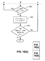
三角形分割マップは、三角形分割マップのベクトル数に関連する線形時間において、任意の画素に対する変位の判定を可能とするため、変位を判定するために使用されてもよい。ドローネ最適三角形分割は、他の三角形分割方式よりも平滑である特性を有するため、使用されてもよい。図14(a)、図14(b)及び図14(c)を参照して、点Pの2次元配列に対する三角形分割のフィールドについて次に説明する。 The triangulation map may be used to determine the displacement to allow determination of the displacement for any pixel in the linear time associated with the number of vectors in the triangulation map. Delaunay optimal triangulation may be used because it has the property of being smoother than other triangulation schemes. Next, the triangulation field for the two-dimensional array of points P will be described with reference to FIGS. 14 (a), 14 (b), and 14 (c).
本明細書で説明される三角形分割は、一般化されたマップ、又は「G-Maps」に基づく。G-Mapsは、矢印(darts)として知られる単一のトポロジー要素の組合せに基づく。図14(a)に示すように、三角形分割G-Mapの矢印1410は、固有の3重(unique triple) d = (Vi, Ej, Tk)である。ここで、Viは頂点1420であり、Ejは辺1430であり、Tkは三角形1440である。各三角形1440に対して、矢印を形成する頂点及び辺の6つの組合せが考えられる。2つの三角形(例えば、1440)により囲まれる各辺に対して、矢印(例えば、1410)を形成する頂点及び三角形の4つの組合せが考えられる。
The triangulation described herein is based on a generalized map, or “G-Maps”. G-Maps is based on a combination of single topology elements known as arrows. As shown in FIG. 14A, the
図14(b)は、矢印α0(d)、α1 (d)及びα2 (d)に対して動作する3つの関数を示す。 FIG. 14B shows three functions that operate on arrows α 0 (d), α 1 (d), and α 2 (d).
(i)α0(d)は、異なる頂点に対して、同一の辺及び三角形を有する3重d'を判定するために、使用されてもよい。 (I) α 0 (d) may be used to determine a triple d ′ having the same side and triangle for different vertices.
(ii)α1(d)は、異なる辺に対して、同一の頂点及び三角形を有する3重d'を判定するために、使用されてもよい。 (Ii) α 1 (d) may be used to determine a triple d ′ having the same vertex and triangle for different sides.
(iii)α2 (d)は、異なる三角形に対して、同一の辺及び頂点を有する3重d'を判定するために、使用されてもよい。 (Iii) α 2 (d) may be used to determine a triple d ′ having the same side and vertex for different triangles.
ある三角形分割トポロジーにおける矢印dに対して、上述の関数(i)〜(iii)の各々は、最大1つの3重d'にマッピングし、各マッピングは、特性αi (αi(d)) = dを有する全単射(bijection)である。ある順番で、関数(i)〜(iii)を組み合わせることにより、ある三角形分割の全ての矢印に従って実行されてもよい。このため、これら関数(i)〜(iii)は、α繰返し子(α-iterators)としても知られる。関数(i)〜(iii)の上述の定義から、ある矢印d1を含む三角形の周囲を移動するために、三角形の周囲で同一の方向を指す他の矢印が、次式(33)及び(34)に従って判定される。 For an arrow d in a triangulation topology, each of the above functions (i) to (iii) maps to a maximum of one triple d ′, each mapping having the characteristic α i (α i (d)) Bijection with = d. It may be performed according to all the arrows of a certain triangulation by combining the functions (i) to (iii) in a certain order. For this reason, these functions (i) to (iii) are also known as α-iterators. From the above definition of the functions (i) to (iii), in order to move around the triangle including the arrow d 1 , another arrow pointing in the same direction around the triangle is represented by the following equations (33) and (33) 34).
dの「左側」の領域及びdの「右側」の領域が、規定されてもよい。これらは、それぞれ、三角形Tkが常にベクトルの左側に現れる平面において、線Ejに沿って、Viの始点を使用して形成されるベクトルの左側の領域及び右側の領域である。 The “left” region of d and the “right” region of d may be defined. These are the left and right regions of the vector formed using the starting point of V i along line E j in the plane where triangle T k always appears on the left side of the vector, respectively.
複数の点Pのドローネ三角形分割(Delaunay triangulation)(は、三角形の最小内角(minimum interior angles)を最大にするPの三角形分割であり、三角形分割の境界ベクトルがPの凸包であることを前提とする。各三角形の最小内角を最大にすることは、各三角形の外接円がPの任意の点を囲まない(外接円(circumcircle)チェックとして知られる)ことを保証することに等しい。そのような三角形の辺は、「局部的に最適」であるとして知られる。全ての辺が局部的に最適である場合のみ、三角形分割は、ドローネ最適(Delaunay optimal)である。非最適な三角形分割から最適な三角形分割を作成するため、一連の辺は、交換される。厳密な凸四角形(三角形分割の2つの三角形により形成される)の対角線上のある辺に対して、1つの三角形の外接円が四角形の4つ目の頂点を囲む場合、辺は、交換される。辺の交換は、四角形の1つの対角線からもう1つの対角線に辺を移動することを含む。そのような方法を三角形分割に対して繰り返し適用することにより、三角形分割は、最大N回の繰返しで最適な状態に収束する。尚、Nは、三角形分割の頂点の数を表す。 Delaunay triangulation (multiple points P is a triangulation of P that maximizes the minimum interior angles of the triangle, assuming that the boundary vector of the triangulation is a convex hull of P Maximizing the minimum interior angle of each triangle is equivalent to ensuring that the circumcircle of each triangle does not enclose any point in P (known as a circumcircle check). Triangular edges are known to be “locally optimal.” Triangulation is Delaunay optimal only if all edges are locally optimal. To create an optimal triangulation, a series of edges are swapped: one triangular circumscribed circle for a diagonal side of a strictly convex quadrilateral (formed by two triangles of the triangulation) Is the fourth square When enclosing a point, the sides are swapped, which involves moving the sides from one diagonal of the quadrangle to the other, applying such a method to the triangulation repeatedly. Thus, the triangulation converges to an optimum state after a maximum of N iterations, where N represents the number of vertices of the triangulation.
最適化されたドローネ三角形分割(を複数の点Pから作成するため、増分アルゴリズムが使用されてもよい。増分三角形分割アルゴリズムを使用するために、初期三角形分割が作成され、Pからの各点がΔに挿入される。ここで、Δは、各挿入の後、再最適化される。使用された初期三角形分割は、Pの全ての点を囲む四角形を対角線状に分割することにより生成された三角形分割である。1つの実現方法において、境界点がPの全ての点から遠距離であるようにするため、この四角形は、画像のサイズより10倍大きくなるように選択されてもよい。これは、境界点からの影響が最小限であることを示す。PのN個のノードを含む三角形分割ΔNに、Pからのノードpを追加するために、pを含むΔNの三角形Tiの位置が特定され、三角形Tiは、3つのサブ三角形に分割される。三角形Tiは、点pから開始し、Tiの3つの頂点まで拡張する辺を作成することにより、3つのサブ三角形に分割される。頂点交換方法2800(図28を参照)は、3つのサブ三角形に適用される。方法2800は、全ての辺が局部的に最適となるまで、外接円チェックを非最適な辺に対して適用する。従って、三角形分割ΔN+1は、ドローネ最適である。Pからのノードpの三角形分割ΔNへの追加について、以下に更に説明する。
An incremental algorithm may be used to create an optimized Delaunay triangulation (from multiple points P. To use the incremental triangulation algorithm, an initial triangulation is created and each point from P is Is inserted into Δ, where Δ is re-optimized after each insertion, and the initial triangulation used was generated by diagonally dividing the rectangle surrounding all points in P In one implementation, this quadrilateral may be selected to be 10 times larger than the size of the image so that the boundary points are far from all points in P. Indicates that the influence from the boundary points is minimal: to add the node p from P to the triangulation Δ N containing N nodes of P, the triangle T i of Δ N containing p is is located, the triangle T i has three sub Is divided into square. Triangle T i starts from point p, by creating an edge that extends to the three vertices of T i, a. Vertexes exchange method 2800 (FIG. 28 which is divided into three sub-triangles Is applied to three sub-triangles, and
点pが存在するΔNの三角形Tiの位置を特定するため、三角形分割の各三角形がチェックされる。図27を参照して、ある三角形Tiに点pが存在するかを判定する方法2700を次に説明する。方法2700は、ハードディスクドライブ110に常駐し、且つ、実行の際には、プロセッサ105により制御されるソフトウェアとして実現されてもよい。
To identify the position of the triangle T i of delta N of point p is present, each triangle of the triangulation is checked. With reference to FIG. 27, a
方法2700は、ステップ2710において、変数iを0に初期化することにより開始する。次のステップ2720において、三角形Tiの初期矢印が選択され、変数diに割り当てられる。ステップ2720において、三角形Tiのいずれの矢印が、選択されてもよい。次のステップ2730において、プロセッサ105が、pがdiの「左側」(先に規定したように)に位置すると判定すると、ステップ2740に進む。あるいは、pがdiの左側に位置しない場合、pはTi内に位置せず、方法2700は終了する。
ステップ2740において、変数iは、1増分され、ステップ2750に進む。プロセッサ105が、ステップ2750において、iが3に等しいと判定すると、三角形Tiの全ての3辺は、ある方向で考慮され、pは、三角形Tiの全ての辺の左側にある。pが三角形Tiの全ての辺の「左側」にある場合、pは三角形Ti内に位置し、方法2700は終了する。プロセッサ105が、ステップ2750において、iが3に等しくないと判定する場合、ステップ2780に進み、次に検査されるべき矢印が判定される。次に検査されるべき矢印は、次式(35)を使用して判定されてもよい。
In
![]()
![]()
ステップ2780の後、ステップ2730に戻り、ステップ2720において選択された次の矢印に対して、pがチェックされる。pが存在する三角形(すなわち、Ti)が判定されるまで、方法2700は、三角形分割ΔNの各三角形に適用される。以下に説明するように、方法2700は、ある点における補間に対して使用される三角形を判定するために、使用されてもよい。
After
三角形の周囲に続くパスは、diの2周分として知られる。上述の方法2700は、以下に説明するように、補間に対して使用されるべき三角形を判定するために使用されてもよい。
The path that goes around the triangle is known as d i two rounds. The
pから三角形Tiの3つの頂点に対して辺を作成することにより、Tiを3つのサブ三角形に分割し、Tiの点を使用して3つの新しい辺を作成する。これにより、3つの新しい三角形を生成する。例えば、図14(c)に示すように、三角形Tiを3つのサブ三角形に分割することにより、3つの矢印d0、d0'及びd0"を生成する。この3つの矢印d0、d0'及びd0"は、新しい辺のうち1つの辺の左側に現れ、頂点交換方法(vertex swapping method)2800で使用するために、pの逆側に向かっている。矢印d0、d0'及びd0"の任意の1つの矢印が、交換方法2800において使用される。
By creating edges from p for the three vertices of triangle T i , T i is divided into three sub-triangles and the points of T i are used to create three new edges. This generates three new triangles. For example, as shown in FIG. 14C, by dividing the triangle T i into three sub-triangles, three arrows d 0 , d 0 ′ and d 0 ″ are generated. The three arrows d 0 , d 0 ′ and d 0 ″ appear on the left side of one of the new sides and are directed to the opposite side of p for use in the
頂点交換方法2800は、三角形分割ΔNが最適であることを保証する。頂点交換方法2800は、図14(c)に示すように、三角形Ti(点pが挿入された)の辺、Tiの頂点及びTiを囲む3つの三角形の3重を表し、且つ時計方向を向く3つの矢印d1、d2及びd3から開始する頂点を、再帰的に検索及び交換する。3つの矢印d1、d2及びd3は、次式(36)、(37)及び(38)を使用して、上述のd0から判定されてもよい。ここで、明確にするため、α関数の括弧は省略した。
The
図14(c)に示す矢印d1、d2及びd3は、矢印d1、d2及びd3を判定するために、矢印d0が使用されることを前提とする。しかし、矢印d1、d2及びd3は、矢印d1、d2及びd3の定義を交換する他の矢印d0'及びd0"のいずれか一方を使用して判定されてもよい。 The arrows d 1 , d 2, and d 3 shown in FIG. 14C are based on the assumption that the arrow d 0 is used to determine the arrows d 1 , d 2, and d 3 . However, the arrows d 1 , d 2 and d 3 may be determined using any one of the other arrows d 0 ′ and d 0 ″ which exchange the definitions of the arrows d 1 , d 2 and d 3 .
矢印d1、d2及びd3は、各々、頂点交換方法2800に対する入力矢印diとして使用される。図28を参照して、頂点交換方法2800を説明する。方法2800は、ステップ2810で開始する。ステップ2810において、プロセッサ105が、外接円チェックを使用して、矢印diに関連付けられた辺Eiが局部的に最適であると判定すると、方法2800は、矢印diに対して完了し、方法2800が終了する。辺Eiがステップ2810において局部的に最適でない場合、方法2800は、ステップ2820に継続し、次式(39)及び(40)を使用して、2つの新しい矢印が定義される。
Arrow d 1, d 2 and d 3 are each used as input arrow d i for the
その後、ステップ2830に進み、辺Eiは、辺Eiを局部的に最適にするために交換される。次のステップ2840において、プロセッサ105は、新しい矢印di,1に対して、方法2800を繰り返し実行する。その後、ステップ2850に進み、プロセッサ105は、新しい矢印di,2に対して、方法2800を繰り返し実行する。ステップ2850の後、方法2800は、矢印diに対して終了する。
Thereafter, proceeding to step 2830, edge E i is exchanged to locally optimize edge E i . At
最適ドローネ三角形分割が変位マップDに対して生成されると、ある点を含む三角形は、三角形分割における点の数に対して、線形時間において発見される。方法2700が、ある点を含む三角形を判定するために使用されてもよい。最初に配置された境界点は、変位0が与えられ、変位マップDの中心から遠距離の位置に配置された。従って、描画済ページ画像311内にあるが変位マップDの点の外側にある点の補間に対する境界点の影響は、最小限となる。
When an optimal Delaunay triangulation is generated for the displacement map D, the triangle containing a point is found in linear time with respect to the number of points in the triangulation.
図13の方法1300に戻ると、ステップ1340において、プロセッサ105は、画像の各位置x,yに対する補間された値を判定し、補間された変位マップDresidualを判定する。ステップ1340において、点x,yを含む三角形の位置が特定される。三角形の頂点n0、n1、n2が判定されると、次式(41)を使用して、補間が実行される。
Returning to the
式中、nix及びniyは、それぞれ、頂点niのx座標及びy座標である。Diは、頂点niにおいて比較された変位を表す。 In the equation, n i x and n i y are the x coordinate and y coordinate of the vertex n i , respectively. D i represents the displacement compared at vertex n i .
方法1300は、次のステップ1350において終了する。ステップ1350において、プロセッサ105は、除去された最も適合する1次変換を補間された変位マップDresidualに対して再適用し、次式(42)を使用して歪マップDfine (x, y)を形成する。
The
方法600のステップ605において判定されたように、マップDfine (x, y)は、粗位置合わせ走査済ページ画像312の各画素を、対応する描画済ページ画像311の座標空間の画素に関連付ける歪マップを形成する。
As determined in
方法1000に戻ると、次のステップ1007において、プロセッサ105は、走査済ページ画像320の粗位置合わせがまだ実行されていない走査済ページ画像312にアクセスする。プロセッサ105は、粗位置合わせ処理により生成されたパラメータ及び歪マップDfine(x, y)を使用し、図3に示すように、精細位置合わせページ画像を、複数の精細位置合わせページ画像340に対して出力する。精細位置合わせページ画像340の各ページ(例えば、313)は、描画済ページ画像310の対応する描画済ページ画像(例えば、311)に対して位置合わせされる。
Returning to the
ステップ1007において、プロセッサ105は、歪マップDfine(x, y)が描画済ページ画像310の画素を走査済ページ画像320の画素に関連付ける変位マップを形成するように、歪マップDfine(x, y)を変更する。プロセッサ105は、次式(43)に従って、粗位置合わせ中に判定した線形平行移動パラメータを、歪マップDfine(x, y)に追加する。
In
対応する描画済ページ画像311の画素に対応する特定の走査済ページ画像312の画素は、変位マップDを使用して、描画済ページ画像311の点に対応する走査済ページ画像312上のサブピクセルの場所を判定し、且つその場所において走査済ページ画像312の色値を補間することにより発見されてもよい。そのような補間は、3次補間法(bicubic)であってもよい。
The pixels of the particular scanned
ステップ1007を実行するために、特定の描画済ページ画像(例えば、311)に対して、空の画像が、メモリ106又はハードディスクドライブ110に生成される。空の画像の各画素に対して、座標(x, y)が、ワープマップDwarp(x, y)の対応する画素から取得される。この座標(x, y)は、描画済ページ画像311に対応する走査済ページ画像312の値を補間により判定するために、使用されてもよい。補間された値、及びワープされた画像は、特定の赤、緑、青(RGB)の強度成分において、いくつかの成分を含む。補間された値は、作成された画像に格納され、精細位置合わせページ画像340を形成してもよい。
To perform
方法200に戻ると、方法200のステップ250における精細位置合わせページ画像340の形成後、次のステップ260において、プロセッサ105は、精細位置合わせページ画像340の色を、描画済ページ画像310の色に色合わせする。
Returning to the
文書300の色は、文書300の印刷及び走査を介して、大きく変更される可能性がある。2つの画像間の有効な差異のみを抽出するため、2つの画像の色が、合わされてもよい。
The color of the
色合わせは、ステップ260において、位置合わせページ画像340を描画済ページ画像310と比較し、画像間における異なる色成分の変化を判定することにより実行される。色合わせを実行する際、位置合わせページ画像340の色は、特定のモデルに従った予測可能な方法で変化すると考えられる。色合わせは、モデルのパラメータを判定し、予測される誤差を最小限にする。本明細書で説明するように、位置合わせページ画像340の色は、アフィン変換(すなわち、1次多項式モデル)が実行されると考えられる。しかし、他のモデルが使用されてもよい。例えば、ガンマ修正モデル又はn次多項式モデルが、ステップ260において、色合わせを実行するために使用されてもよい。
Color matching is performed in
描画済ページ画像(例えば、311)の画素の色が走査又は印刷を介してアフィン変換された場合、画素の色は、次式(44)に従って変換される。 When the pixel color of the rendered page image (for example, 311) is affine transformed through scanning or printing, the pixel color is transformed according to the following equation (44).
式中、Pi predictedは、アフィン変換モデル(affine transformation model)に従って予測された元の色成分(color components)を表し、Pi originalは、描画済画像(rendered image)の色成分を表す。色成分P1、P2、P3は、それぞれ、赤、緑及び青(RGB)成分を示す。 Where P i predicted represents the original color components predicted according to the affine transformation model, and P i original represents the color component of the rendered image. The color components P 1 , P 2 , and P 3 indicate red, green, and blue (RGB) components, respectively.
ステップ260において、プロセッサ105は、予測された色における誤差が最小限となるように、行列A、Cを判定する。誤差は、次式(45)に従って判定されてもよい。
In
式中、総和は、位置合わせページ画像340の精細位置合わせページ画像(例えば、313)の全ての画素を合計し、Pi predictedは、合計された精細位置合わせページ画像313の画素の色成分を表す。
Wherein the sum is finely registered page images of registered page image 340 (e.g., 313) sums all the pixels of the P i predicted, the total color components of the pixel of finely registered
E2が最小化されるようにA、Cの各要素のパラメータを発見するために、A、Cの要素に対するe2の導関数は、以下のように、ゼロ(0)となることが必要とされる。 In order to find the parameters of each element of A and C so that E 2 is minimized, the derivative of e 2 for the elements of A and C must be zero (0) as follows: It is said.
式中、pは、使用されるモデルのパラメータである。アフィン変換の場合、使用されるパラメータは、Aij及びCiである。式(46)は、次式を与えるように書き換えられてもよい。 Where p is a parameter of the model used. For affine transformation, the parameters used are A ij and C i . Equation (46) may be rewritten to give:
アフィン色変換の場合: For affine color conversion:
次式(50)、(51)に従って、2つの新しい行列M、Lが定義される場合、全ての総和が全ての画素に渡ることを前提とする。 When two new matrices M and L are defined according to the following equations (50) and (51), it is assumed that all the sums are over all the pixels.
次式(52)は、誤差e2を最小化するA、Cに対する値を発見するために使用されてもよい。 Following equation (52), A to minimize the error e 2, it may be used to find a value for C.
ステップ260において実行されたように、精細位置合わせページ画像340の色を描画済ページ画像310に色合わせする方法1500を、図15を参照して、次に説明する。方法1500は、ハードディスクドライブ110に常駐し、且つ、実行の際には、プロセッサ105により制御されるソフトウェアとして実現されてもよい。
A
方法1500は、ステップ1510で開始し、プロセッサ105は、精細位置合わせページ画像(例えば、313)及び対応する描画済ページ画像(例えば、311)にアクセスする。次のステップ1520において、プロセッサ105は、メモリ106内に構成される4つの構成を、ゼロを含むように初期化する(構成は、0に索引付けされる)。これらの構成の第1の構成は、4×3の行列Lである。第2の構成は、4×4の行列Mである。第3の構成は、4要素ベクトルRであり、第4の構成は、3要素ベクトルOである。次のステップ1530において、描画済ページ画像313の未処理の各画素Pi originalに対して、対応する未処理の画素Pi registeredが、精細位置合わせページ画像313から選択される。未処理の画素Pi originalは、処理のために、x,yの順に選択されてもよい。Pi originalに最も類似し、且つPi originalと同一位置に中央が位置決めされた5画素×5画素の四角形内に存在する画素を選択することにより、対応する未処理の画素Pi registeredが選択されてもよい。類似度(similarity)は、これに関して、次式(53)を使用して評価される。
式(53)は、2つの画素が同一である場合、si = 0という結果になる。2つの画素が類似していない程、siの値は低くなる。 Equation (53) results in si = 0 when the two pixels are identical. The less similar the two pixels are, the lower the value of si.
方法1500は、次のステップ1540に継続し、未処理の画素Pi registeredの赤、青及び緑(RGB)の色成分は、メモリ106内に構成される4要素ベクトルRに格納される。赤、青及び緑の色成分は、それぞれ、R[1]、R[2]及びR[3]に格納され、R[0]は、1に設定される。
The
方法1500は、次のステップ1550に継続し、未処理の画素Pi originalの赤、緑及び青(RGB)の色成分は、メモリ106内に構成される3要素ベクトルOに格納される。未処理の画素Pi originalの赤、緑及び青の色成分(RGB)は、それぞれ、O[0]、O[1]及びO[2]に格納される。
The
方法1500は、次のステップ1560に継続し、行列Mの各要素は、次式(54)を使用して変更される。
The
![]()
![]()
次のステップ1570において、行列Lの各要素は、次式(55)を使用して変更される。
In the
![]()
![]()
方法1500は、次のステップ1580に継続し、プロセッサ105が、位置合わせページ画像313に未処理の画素が存在すると判定する場合、ステップ1530に戻る。あるいは、位置合わせページ画像313の全ての画素が処理された場合、ステップ1590に進む。ステップ1590において、プロセッサ105は、式(52)を使用して、行列A及びCを判定する。行列A及びCは、メモリ106又はハードディスクドライブ110に格納されてもよい。
The
行列A及びCが判定されると、色合わせは、実行されてもよい。式(44)は、複数の描画済ページ画像310の描画済ページ画像312の各画素に対して適用され、色合わせされた描画済ページ画像を形成する。方法1500は、描画済ページ画像310及び精細位置合わせページ画像340の対応する画像の各対(例えば、311及び313)に対して、繰り返されてもよい。
Once the matrices A and C are determined, color matching may be performed. Equation (44) is applied to each pixel of the rendered
ステップ260において、方法1500に従った色合わせを実行した後、ステップ270に進む。ステップ270において、変更リストAは、メモリ106又はハードディスクドライブ110に生成される。変更リストAは、図3に示すように、変更済ページ350を生成するために使用されてもよい。精細位置合わせページ画像340の精細位置合わせページ画像(例えば、313)の各画素に対して、色合わせされた描画済ページ画像の最小限必要とされる画素のエネルギー変化(ΔEmin)が、隣接する画素における変化に基づいて判定される。例えば、場所x1,y1及びx2,y2に各々位置する2つの画素P1及びP2の場合、赤、緑及び青(RGB)の色空間において、画素P1に対して、R1、G1及びB1の−1と1との間の色値を有し、画素P2に対しては、R2、G2及びB2の−1と1との間の色値を有する。2つの画素P1及びP2間のエネルギー差ΔEは、次式(56)に従って定義される。
After performing color matching according to
![]()
![]()
場所x,yにおける画素に対するΔE minの値は、次式(57)を使用して、領域に対する最小のΔEの値を見つけることにより判定されてもよい。 The value of ΔE min for the pixel at location x, y may be determined by finding the minimum ΔE value for the region using equation (57):
式中、Pf [x,y]は、場所x,yにおける精細位置合わせ画像(例えば、313)の画素を表し、Pc [x',y']は、場所x',y'における対応する色合わせされた描画済ページ画像(例えば、311)の画素を表す。また、KBは、四角形のサイズを表す。例えば、KBは、2に設定されてもよい。ΔEminの値は、精細位置合わせ画像313全体(すなわち、x,y及びx',y'の全ての有効な組合せ)に対して判定される。ΔEminの値が精細位置合わせ画像313全体に対して判定されると、各画素に対して判定された値は、精細位置合わせページ画像313の左上の画素から開始する閾値ΔElift(例えば、ΔEliftは、0.4になるように選択されてもよい)と比較される。ある場所x,yに対するΔEminの値がΔEliftを超える場合、変更は、その場所における画素に対して、メモリ206内に構成される変更リストAに追加される。
Where P f [x, y] represents the pixel of the finely aligned image (eg, 313) at location x, y and P c [x ′, y ′] is the corresponding at location x ′, y ′ The color-matched drawn page image (for example, 311) is represented. Also, K B denotes the size of the rectangle. For example, K B may be set to 2. The value of ΔE min is determined for the entire finely aligned image 313 (ie, all valid combinations of x, y and x ′, y ′). When the value of ΔE min is determined for the entire
ステップ270において実行されたように、変更リストAを生成する方法1600を、図16を参照して、次に説明する。方法1600は、ハードディスクドライブ110に常駐し、且つ、実行の際には、プロセッサ105により制御されるソフトウェアとして実現されてもよい。
The
方法1600は、変更リストAに追加される変更Anewを生成する。変更リストAは、最初は空である。リスト中の各変更は、後述する更なるデータに加え、精細位置合わせページ画像313のある画素の場所から抽出された画素群を含む。
The
方法1600は、ステップ1610で開始し、プロセッサ105は、精細位置合わせページ画像(例えば、313)から画素Pinitを選択する。次のステップ1620において、新しい変更Anewは、メモリ106に構成され、画素Pinitは、新しい変更Anewに追加される。また、ステップ1620において、メモリ106内に構成される探索点のキューQliftの末尾に、画素Pinitの場所x,yを追加することにより、幅優先探索(breadth-first-search)が開始される。探索は、ステップ1630において、キューQliftから場所(x, y)を選択することにより開始する。次のステップ1640において、座標x',y'を有するステップ1630で選択された場所は、x-KG < x' < x+KG且つy-KG < y' < y+KGである場合、場所のリストに追加され、リフトLcheckに対してチェックされる。KGは、KB(すなわち、2)と同一の値に設定されてもよい。しかし、KGの値及びKBの値は、同一である必要はない。次のステップ1650において、場所が、Lcheckから選択される。次のステップ1660において、ステップ1650で選択された場所における画素は、選択された画素に対するΔEminの値が最小閾値ΔEstop(例えば、0.016)を超えるかを判定するために、解析される。ステップ1660において選択された画素に対するΔEminの値が最小閾値ΔEstopを超える場合、ステップ1670に進む。ステップ1670において、画素は、新しい変更Anewにコピーされ、画素の場所は、次のステップ1680において、探索点のキューQliftの末尾に追加される。ステップ1660において、ステップ1660において選択された画素に対するΔEminの値が最小閾値ΔEstop以下である場合、ステップ1685に進む。次のステップ1683において、ステップ1670で選択された画素に対するΔEminの値は、否定演算され、画素は、画素に対応する場所の後の探索において、合致しない。
The
ステップ1685において、Lcheckに更に場所が残されている場合、ステップ1650に戻る。そうでなければ、ステップ1690に進む。ステップ1690において、Qliftに場所が残されている場合、ステップ1630に戻り、探索のために、別の場所がキューから取得される。
In
探索点のキューQliftに探索する画素が存在しない場合、変更Anewのバウンディングボックス(bounding box)が、ビットマップとして、メモリ106に記録され、変更Anewは、方法1600のステップ1695において、変更リストAに追加される。バウンディングボックスは、変更Anewを生成するためにステップ1660において判定された画素の場所に対する最小値x'及びy'、並びに最大値x'及びy'を表す。これらの値は、方法1600の実行中に収集される。次のステップ1697において、精細位置合わせページ画像313に未処理の画素が存在する場合、ステップ1610に戻る。そうでなければ、方法1600は、終了する。ΔEminがΔEliftより大きい画像に点が残されていない場合、変更リストAは、完成する。
When the pixel to be searched in the queue Q lift the search points are not present, the change A new new bounding box (bounding box), as a bitmap, recorded in the
図3は、変更リストAに含まれる変更(例えば、317)を含む変更済ページ350を示す。リストAの変更は、ずれによる雑音、及び描画済ページ画像311と精細位置合わせページ画像313との間の他の小さな相違点を含む可能性がある。
FIG. 3 shows a modified
変更リストAが完成すると、方法200は、マージステップ290に進み、物理的に分離された変更を論理的にマージし、且つリストAからわずかな変更を除去する。マージステップ290は、4つのサブステップを含む。第1のサブステップ205において、図3に示すように、ホットスポット画像330は、プロセッサ105により生成される。ホットスポット画像330は、テキスト又は図形を既に有するページのエリア(すなわち、「対象」エリア)を表す2値画像である。ステップ205において実行されたように、ホットスポット画像330を生成する方法1700を、図17を参照して、以下に詳細に説明する。
When change list A is complete,
方法200は、次のステップ215に継続し、プロセッサ105は、対象変更を検出する。ステップ215において実行されたように、対象変更を検出する方法1800を、図18を参照して、以下に詳細に説明する。
方法200の次のステップ225において、変更は、ホットスポット画像330を使用してマージされる。ステップ225において実行されたように、変更をマージする方法1900を、図19を参照して、以下に説明する。方法200は、マージ済変更の最終リストがプロセッサ105により生成される次のステップ235で終了する。次に、ステップ205、215、225及び235を詳細に説明する。
In the
上述のように、ホットスポット画像330は、テキスト又は図形を既に有するページのエリア(すなわち、「対象」エリア)を表す2値画像である。1の値が、文書300のページ(例えば、301)上の対象エリアを表現するために使用されてもよい。更に、0の値は、文書300のページ301上の非対象エリアを表現するために使用されてもよい。変更がページ301の生成された1つ以上の対象エリアに大きく交差する場合、文書300のページ301に対する変更は、対象であると考えてもよい。変更が対象エリアに交差する量は、本明細書において、「対象性」と呼ぶ。変更の対象性又は変更が対象エリアに交差する量は、変更が参照するテキストの識別を可能にする。
As described above, the
ステップ205において実行されたように、ホットスポット画像(hotspot images)330を生成する方法1700を、図17を参照して、次に詳細に説明する。方法1700は、ハードディスクドライブ110に常駐し、且つ、実行の際には、プロセッサ105により制御されるソフトウェアとして実現されてもよい。
The
方法1700は、ステップ1701で開始し、描画済ページ画像のうちの1つの画像(例えば、311)は、プロセッサ105により、メモリ106又はハードディスクドライブ110からアクセスされ、説明の目的のため、現在の描画済ページ画像となる。次のステップ1703において、プロセッサ105は、現在の描画済ページ画像311の第1の画素(すなわち、現在の画素)を解析する。その後、ステップ1705において、現在の画素に対するYUV色値のY色成分が所定の白の閾値Wminより小さい場合、あるいは、U又はV色成分がゼロでない場合、次のステップ1707において、現在の画素及びその画素の水平方向に隣接する画素(すなわち、左右に均等に分配される隣接する画素)のKhotは、対象としてマークされる。そうでなければ、ステップ1709に直接進む。現在の描画済ページ画像311の対象画素にマークする情報は、現在の描画済ページ画像311に対するホットスポット画像(例えば、314)として、メモリ106又はハードディスクドライブ110に格納される。1つの実現方法において、Wminは、Y値の最大である可能性のある0.8の値に設定されてもよく、Khotは、16になるように選択されてもよい。ステップ1709において、現在の描画済ページ画像311に処理されるべき画素が残されている場合、ステップ1701に戻り、現在の描画済ページ画像311の次の画素を処理する。そうでなければ、ステップ1711に進む。ステップ1711において、処理されるべき描画済ページ画像が存在する場合、ステップ1701に戻る。そうでなければ、方法1700は終了する。
The
方法1700に従うホットスポット画像330の生成は、描画済ページ画像310のみを必要とし、上述の位置合わせ及び色のマッチングとは無関係である。従って、ホットスポット画像330の生成は、位置合わせ及び色のマッチングの前に実行されてもよい。これにより、ページ画像(例えば、301、302、303等)は、1度のみロードされる必要があり、その後、変更されてもよい。
Generation of the
次に、図18を参照して、対象変更を検出する方法1800を詳細に説明する。方法1800は、ハードディスクドライブ110に常駐し、且つ、実行の際には、プロセッサ105により制御されるソフトウェアとして実現されてもよい。方法1800において、プロセッサ105は、変更リストAの各変更に対して、繰り返し処理を行う。変更リストAの各変更に対して、対象エリアが判定される。
Next, a
方法1800は、最初のステップ1810で開始し、プロセッサ105は、変更リストAから変更Aを選択する。次のステップ1820において、未処理の画素Pcheckが、選択された変更Aから選択される。変更A及び画素Pcheckは、ホットスポット画像330の特定のホットスポット画像(例えば、314)に対応する。次のステップ1830において、プロセッサ105が、画素Pcheckが対応するホットスポット画像314において対象であるとマークされると判定すると、ステップ1840に進む。ステップ1840において、プロセッサ105は、変更Aに対して、新しい候補対象エリアを作成する。次のステップ1850において、画素Pcheckの隣接する画素(水平方向及び垂直方向に)は、探索点のキューQsearchに追加される。
方法1800は、次のステップ1860に継続し、プロセッサ105は、探索点のキューQsearchから画素Pを選択する。その後、ステップ1870において、ステップ1860で選択された画素が変更Aにコピーされ、且つ対応するホットスポット画像314において対象であるとマークされた場合、ステップ1875に進む。そうでなければ、ステップ1880に進む。ステップ1875において、候補対象エリアは、画素Pを含むように拡張され、画素Pの隣接する画素は、探索点のキューQsearchに追加される。また、ステップ1875において、プロセッサ105は、画素Pに対して、もう対象ではないことをマークする。次のステップ1880において、プロセッサ105が、キューQsearchに画素が更に残されていると判定する場合、ステップ1860に戻り、別の画素が検査される。そうでなければ、ステップ1885に進み、対象エリアは、メモリ106内に構成される候補対象エリアのリスト中の変更Aと共に、メモリ106に格納される。
The
方法1800は、次のステップ1890に継続し、未処理の画素が変更Aに残されている場合、ステップ1820に戻る。そうでなければ、候補エリアのリストは完成し、ステップ1895に進む。ステップ1895において、候補対象エリアのリスト中の各候補対象エリアに対して、ステップ1870の条件を満足する対象エリアの画素数が、閾値Aminと比較される。ステップ1870の条件を満足する対象エリアの画素数がAminより小さい場合、対象エリアは、廃棄される。候補対象エリアが候補対象エリアのリストに追加される前に、ステップ1885において、ステップ1895が、代わりに実行されてもよい。ステップ1870の条件を満足する特定の対象エリアの画素数を閾値Aminと比較することは、騒音の影響を減少し、また、対象となるために、変更及び変更に対するテキスト又は図の有効なオーバーラップを必要とする。画素数がAminより大きい場合、対象エリアは、候補対象エリアのリスト中に保持される。Aminは、150に設定されてもよい。従って、候補対象エリアに対するバウンディングボックスは、変更が対応するホットスポット画像314の対象画素にオーバーラップする場所毎に判定される。全ての候補対象エリアが特定の変更に対して判定されると、バウンディングボックスにより囲まれる最大エリアを有する候補対象エリアは、変更に対する対象エリアとなるように選択され、変更は、対象であるとしてマークされる。候補対象エリアが候補対象エリアのリストに残されていない場合、変更は、対象とならないことがマークされる。
The
変更リストAの変更の対象性が、方法200のステップ215において判定されると、方法200の次のステップ225において、変更は、クラスタリングアルゴリズムを使用してマージされる。変更の複数の対の各々に対するコスト関数のコスト値を判定し、且つ所定の閾値よりも小さいコスト値を有する変更の対をマージすることにより、変更がマージされてもよい。
Once the relevance of change list A is determined in
ステップ225において実行されたように、変更をマージする方法1900を、図19を参照して、次に詳細に説明する。方法1900は、ハードディスクドライブ110に常駐し、且つ、実行の際には、プロセッサ105により制御されるソフトウェアとして実現されてもよい。
The
方法1900は、ステップ1901で開始し、プロセッサ105は、メモリ106又はハードディスクドライブ110内に、変更の対のリストを生成する。変更の対のリストは、可能性のある全ての変更の対を含む。次のステップ1903において、変更の対のリスト中にある変更の各対に対して、プロセッサ105は、コストを表すコスト値を判定し、その対における変更をマージする。ステップ1903において実行されたように、2つの変更をマージするためのコスト値を判定する方法2300を、図23を参照して、以下に説明する。
方法1900は、次のステップ1905に継続し、プロセッサ105は、マージするためのコストが最低である変更の対が最初にマージされるように、変更の対のリストをソートする。次のステップ1907において、最低関連コスト値を有する変更の対が、マージされる。変更の対がマージされると、その対は、2つのサブ変更を有する単一の変更となる。その結果、追加の変更をマージするコストは、変化する可能性がある。これは、変更が、全体のバウンディングボックスを有し、また、各々が自身のバウンディングボックスを有する任意の数のサブ変更を含んでもよいからである。サブ変更を含む変更のバウンディングボックスは、全てのサブ変更バウンディングボックスを含むことができる最小の矩形である。全体の変更が変化するため、変更の対がマージされる度に、その変更の対を残りの変更に結び付けるコストは、再判定される。従って、次のステップ1909において、プロセッサ105が、所定のマージ閾値CMERGE(例えば、CMERGE = 2)より小さい関連コスト値を有する変更の対が存在すると判定すると、ステップ1903に戻る。そうでなければ、方法1900は、終了する。方法1900は、新しくマージされた変更の対を含む変更の対毎に、繰り返される。
方法1900は、ページ単位(例えば、ホットスポット画像314毎、及び対応する変更済ページ画像352毎)で実行される。例えば、異なる変更済ページ350からの変更をマージするコストは、暗黙的に無限であり、考慮されない。しかし、1つの実現方法において、異なる変更済ページ350からの変更をマージするコストが、判定されてもよい。変更(例えば、331及び333)をマージするコストは、対象性、変更の形状、及びサブ変更のバウンディングボックス間の最小距離に基づいて判定される。マージ方法1900は、2度実行されてもよい。方法1900の第1の実行において、非対象変更が、考慮されマージされてもよい。方法1900の第2の実行において、対象及び非対象の双方の変更が、考慮されマージされてもよい。方法1900を2度実行することにより、非対象変更がマージされ、コスト判定は、単に、変更の形状及び場所に基づく。方法1900の第2の実行において、最大1つの非対象変更が、各対象変更にマージされてもよく、2つの対象変更は、マージされない。最低コストのマージが最初に実行されるため、対象変更は、隣接する最低コストの変更にマージされ、他の変更にはマージされない。
The
2つの非対象変更をマージする場合、変更をマージするコストの判定は、2つの変更の隣接する2つのサブ変更の間の距離に基づく。ここで、x方向及びy方向の距離は、存在するサブ変更の形状により変倍される。変倍は、同一の方向で変更を好適にマージし、手書きのテキストの語句を好適にマージするために使用される。例えば、変更の幅が変更の高さよりも相当大きい場合、変更は、水平方向に書かれたと仮定される。その結果、その変更を水平方向の別の変更とマージするコストは、その変更を上下同一の距離の別の変更とマージするコストよりも低い。1つの実現方法において、2つの対象変更は、マージされない。従って、以下に詳細に説明するように、少なくとも1つの対象サブ変更を含む2つの変更をマージするコストは、マージ閾値CMERGEよりも大きいある値になるように定義される。 When merging two non-target changes, the cost determination of merging changes is based on the distance between two adjacent sub-changes of the two changes. Here, the distance in the x direction and the y direction is scaled according to the existing sub-change shape. Scaling is used to preferably merge changes in the same direction and preferably merge words of handwritten text. For example, if the change width is significantly greater than the change height, the change is assumed to have been written horizontally. As a result, the cost of merging the change with another change in the horizontal direction is lower than the cost of merging the change with another change of the same distance up and down. In one implementation, the two target changes are not merged. Thus, as will be described in detail below, the cost of merging two changes including at least one target sub-change is defined to be some value greater than the merge threshold C MERGE .
ステップ1903において実行されたように、2つの変更A1及びA2(この2つは、異なり、且つ非対象であると仮定される)をマージするためのコスト値を判定する方法2000を、図20を参照して、以下に説明する。方法2000は、最初のステップ2001で開始し、プロセッサ105が、変更A1及びA2のバウンディングボックスのうち大きい方の幅Mxが変更A1及びA2のバウンディングボックスのうち大きい方の高さMyよりも小さいと判定する場合(すなわち、Mx < Myの場合)、ステップ2003に進む。そうでなければ、ステップ2007に進む。次のステップ2003において、A1又はA2からのサブ変更のうち最大の幅Cxが、A1又はA2からのサブ変更のうち最大の高さCyよりも小さい場合、ステップ2005に進む。そうでなければ、ステップ2013に進む。ステップ2005において、プロセッサ105は、Cy = Cx/KFONTを設定する。式中、KFONT = 1.6である。次のステップ2013において、プロセッサ105は、Cx = Cx/KPを設定する。式中、KP = 2である。
A
ステップ2007において、A1又はA2からのサブ変更のうち最大の幅CyがA1又はA2からのサブ変更のうち最大の高さCxよりも小さい場合、ステップ2009に進む。そうでなければ、ステップ2011に進む。ステップ2009において、プロセッサ105は、Cx = Cy/KFONTを設定する。式中、KFONT = 1.6である。ステップ2011において、プロセッサ105は、Cy = Cy/KPを設定する。式中、KP = 2である。
In
次のステップ2014において、Cx及びCyの値は、定数CMINとCMAXとの間になるように固定される。ここで、CMIN = 15及びCMAX = 200である。次のステップ2015において、プロセッサ105は、Costの値(すなわち、変更をマージするコスト)を無限大に初期化する。次のステップ2017において、プロセッサ105は、A1及びA2中のサブ変更A'1及びA'2の対を選択する。次のステップ2019において、プロセッサ105は、Cost = min(Cost, Dweighted (A'1, A'2, Cx, Cy))を設定する。式中、Dweightedは、A'1及びA'2の変倍されたバウンディングボックス間の最短距離を表す。図21を参照して、サブ変更A'1、A'2に対して、Dweightedの値を判定する方法2100を、以下に説明する。次のステップ2021において、A1及びA2中にサブ変更が更に存在する場合、ステップ2017に戻る。そうでなければ、方法2000は終了する。
In the
図21を参照して、サブ変更A'1、A'2に対して、Dweightedの値を判定する方法2100を、以下に説明する。方法2100は、ハードディスクドライブ110に常駐し、且つ、実行の際には、プロセッサ105により制御されるソフトウェアとして実現されてもよい。
With reference to FIG. 21, a
方法2100は、最初のステップ2101において開始する。ステップ2101において、プロセッサ105は、サブ変更A'1、A'2のバウンディングボックスのコピーを判定し、そのコピーを、メモリ106又はハードディスクドライブ110に格納する。次のステップ2103において、プロセッサ105は、バウンディングボックスのコピーのx及びyの値を、1/Cx及び1/Cyで変倍する。次のステップ2105において、プロセッサ105は、変倍された2つのバウンディングボックス間の最短距離Dweightedを判定する。
The
全ての変更が上述のようにマージされると、方法200は、プロセッサ105がマージ済変更の最終リストを生成する次のステップ235で終了する。マージ済変更の最終リストは、メモリ106又はハードディスクドライブ110に格納されてもよい。マージ済変更の各々は、変更済ページ350の1つのページ(例えば、352、353)に関連付けられ、変更済ページ350の各々は、元のデジタル文書300の対応するページ(例えば、301)に関連付けられる。図3は、複数のページ360を示し、複数のページ360のページ315は、マージ済変更316、317、319及び321を示す。
Once all changes have been merged as described above, the
上述のように、方法200は、ワードプロセシングアプリケーションの1つ以上のソフトウェアモジュールとして実現されてもよい。しかし、描画済ページ画像310及び走査済ページ画像320が生成されると、デジタル文書300は、必要とされない。従って、変更のリフト及びマージは、MFP(複合機)装置等の1つ以上の個別のアプリケーション又は異なる場所で判定されてもよい。
As described above, the
マージ済変更316、317、319及び321は、デジタル文書300とは無関係に、文書独立ファイル形式で、メモリ106又はハードディスクドライブ110に格納されてもよい。あるいは、マージ済変更316、317、319及び321は、マージ済変更316、317、319及び321が必要とされるまで、MFPにより格納されてもよい。1つの実現方法において、マージ済変更316、317、319及び321は、デジタル文書300と共に、文書ファイルにメタデータとして格納されてもよい。
図22を参照して、アンカーポイントTn,bestにおいて、変更Anをデジタル文書300に挿入する方法2200を、次に説明する。アンカーポイントは、文書中の画像が「流れる」デジタル文書における場所である。他のテキスト又は画像がデジタル文書において変化した場合、ドキュメントフローは、デジタル文書のページ上のテキスト及び画像の再位置付けを参照する。例えば、テキストで満たされたページの最上部に、空の行を挿入する場合、テキストは、1行下に流れ、一部のテキストは、次のページに流れる。ユーザが一部のテキストを変更した(例えば、注釈付け/又は補正する)場合、変更は、変更が参照するテキストと共に流れることが好ましい。方法2200は、ハードディスクドライブ110に常駐し、且つ、実行の際には、プロセッサ105により制御されるソフトウェアとして実現されてもよい。
With reference to FIG. 22, the
方法2200は、最初のステップ2201で開始し、プロセッサ105は、デジタル文書300についての情報を判定する。この情報は、文書300中の全ての語句の中間点のページ番号及びページの場所(すなわち、ページの左上を基準として)を含む。次のステップ2203において、ステップ2201で収集された情報は、メモリ106内に構成される文書テキストの場所のリストTに格納される。リストTのテキストの場所は、各変更を固定する最適なテキストTn,bestを発見するために使用されてもよい。
方法2200は、次のステップ2205に継続し、変数Dminは、無限大に初期化される(すなわち、Dmin = ()。次のステップ2207において、プロセッサ105が、変更Anが対象として識別されたと判定すると、ステップ2209に進む。そうでなければ、ステップ2211に進む。ステップ2209において、プロセッサ105は、所望のアンカーポイントCnを、変更Anに関連付けられた対象エリアの中心(すなわち、x、y座標において)に設定する。ステップ2211において、プロセッサ105は、所望のアンカーポイントCnを、変更Anのバウンディングボックスの中心(すなわち、x、y座標において)に設定する。次のステップ2213において、プロセッサ105は、文書テキストの場所のリストTから現在のテキストTmを選択する。次のステップ2215において、プロセッサ105が、選択したテキストTmが変更Anと同一の変更済ページ(例えば、352)上にあると判定する場合、ステップ2217に進む。そうでなければ、ステップ2225に進む。ステップ2217において、プロセッサ105は、以下のように、CnとTmとの間の変更済平方距離Dn,mを判定する。
The
式中、Kは、水平方向の距離よりも垂直方向の距離を「長く」するために選択される定数である(例えば、Kは、10として選択される)。水平方向の距離よりも垂直方向の距離を長くするようにKを選択することにより、文書300のページ(例えば、301)上のテキストの不適切な行に変更が固定される可能性は減少される。そのような方法によるKの選択は、テキストの行が文書300のページ(例えば、301)を水平方向に流れることを前提とする。あるいは、縦書き方式が文書300で使用されている場合、Kは、逆に設定されてもよい。変更は、変更の上下の行ではなく、最も近傍のテキストの行に固定されるのが好ましく、これにより、テキストの単一段落内で、より適切な流れが生じる。
Where K is a constant selected to make the vertical distance “longer” than the horizontal distance (eg, K is selected as 10). By choosing K to make the vertical distance longer than the horizontal distance, the possibility of fixing changes to inappropriate lines of text on a page (eg, 301) of the
方法2200は、次のステップ2219に継続し、変更済平方距離Dn,m(
modified square distance)が最短変更済距離Dmin(shortest modified distance)より小さい場合、ステップ2223に進む。そうでなければ、ステップ2225に進む。次のステップ2223において、プロセッサ105は、所定の最短変更済距離Dminを、ステップ2217で判定された変更済平方距離Dn,mに設定する。また、ステップ2223において、プロセッサ105は、アンカーポイントTn,bestをTmに設定する。次のステップ2225において、文書テキストの場所のリストTにテキストTmの場所が更に存在する場合、ステップ2213に戻る。そうでなければ、ステップ2227に進み、プロセッサ105は、変更Anに対するアンカーポイント(anchor point) Tn,bestから変更Anの左上角までのxの距離(すなわち、Δx)及びyの距離(すなわち、Δy)を判定する。次のステップ2229において、プロセッサ105は、判定されたアンカーポイントTn,bestに位置するアンカーを使用して、Δx及びΔyのオフセットで、変更の画像をデジタル文書300に挿入する。方法2200は終了する。
The
If the modified square distance) is smaller than the shortest modified distance D min (shortest modified distance), the process proceeds to step 2223. Otherwise, go to
文書300及び挿入された変更Anのテキストの視覚的オーバーラップ(visual overlap)による混乱を減少するため、変更Anの画像は、文書300のテキストの背後に挿入されてもよく、また、画像の色は、ホワイトニング因子(whitening factor) Wにより白に近付けてもよい。このホワイトニング因子Wは、0.1に設定されてもよい。各色は、赤、緑及び青の色チャネルにおいて、色値により表現されてもよい。各チャネルが0(すなわち、黒)とCMAX(すなわち、最大彩度)との間の値を有する場合、より白い各色値cwhiteは、次式(59)を使用して、元の色corigから判定されてもよい。
To reduce confusion by visual overlap of text in the
![]()
![]()
CMAXは、255に設定されてもよく、これは、8ビット色深さ(8-bitc color depth)として知られる。 C MAX may be set to 255, which is known as 8-bit color depth.
方法200の実現に使用するツールバー2305(図23を参照)、ドキュメントウィンドウ(不図示)、変更リストウィンドウ2410(図24を参照)及びページサマリビューウィンドウ2510(図25を参照)を次に説明する。ツールバー2305、変更リストウィンドウ2410及びページサマリビューウィンドウ2510は、方法200を実現するユーザインタフェースを形成してもよい。ツールバー2305、変更リストウィンドウ2410及びページサマリビューウィンドウ2510は、ハードディスクドライブ110に常駐し、且つ、実行の際には、プロセッサ105により制御される1つ以上のソフトウェアモジュールとして実現されてもよい。
The toolbar 2305 (see FIG. 23), document window (not shown), change list window 2410 (see FIG. 24), and page summary view window 2510 (see FIG. 25) used to implement the
ドキュメントウィンドウ(不図示)は、印刷バージョンの文書300上の変更が現れた場所に固定される変更を有するデジタル文書300を示すWhat You See Is What You Get(「WYSIWYG」)エディタとして実現されてもよい。1つの実現方法において、ドキュメントウィンドウは、MicrosoftTM WordTMを使用して実現されてもよく、変更は、MicrosoftTM WordTMの形態として追加されてもよい。各形態は、文書に固有の形態識別子を使用して、選択され制御されてもよく、これは、各変更と共にメモリ106に格納されてもよい。あるいは、他のワードプロセシングソフトウェア又は単独の文書編集機能を利用する実現が使用されてもよい。
The document window (not shown) may be implemented as a What You See Is What You Get (“WYSIWYG”) editor showing the
ツールバー2305を図23に示す。ツールバー2305は、文書300の変更を制御するためのインタフェースを提供する。ツールバー2305は、上述の方法を開始するためのボタン2310を含む。ツールバー2305は、変更リストウィンドウ2410の可視性を制御するボタン2320と、ページサマリウィンドウ2510の可視性を制御するボタン2330とを更に含む。また、ツールバー2305は、現在の変更に基づいて実行された文書300に対する変更を受け入れ、且つ完了したことを変更にマークするボタン2360を含む。ツールバー2305は、現在の変更を削除し、文書300に対して変更を行わないためのボタン2370を更に含む。完了した変更をクリアするボタン2380が、ツールバー2305に含まれてもよい。ツールバー2305は、完了せずに残されている(すなわち、保留中の)変更数及び完了した変更数を示す表示器2390を更に含んでもよい。ツールバー2305は、保留中の変更のリストの前の変更及び次の変更を選択するボタン2340及び2350を更に含む。ここで、図24に示されるように、保留中の変更は、変更リストウィンドウ2410に示される。変更リストウィンドウ2410は、文書300の保留中の変更及び完了した変更のリストを表示する。後述するように、変更がまだユーザにより受け入れられていない場合、変更は保留中であり、文書300に統合される。リスト中の各変更は、識別子(id)、サイズ及び場所2430等の他の情報と共に、サムネール画像2420として示される。
A
上述の方法が終了すると、表示器2390は、文書300において検出された変更数を示すように構成されてもよい。
When the above method ends,
変更リストウィンドウ2410及びツールバー2305は、検出された変更を受け入れるため又は拒否するために使用されてもよい。例えば、変更は、変更リストウィンドウ2410及びマウス103を従来の方法で使用して、保留中の変更のリストから選択されてもよい。選択された変更は、現在選択されている変更であると考えられる。そのような変更の選択に応答して、プロセッサ105は、選択された変更が対象である場合、選択された変更の対象エリアの下、テキストを選択してもよい。図26を参照して、選択された変更の対象エリアの下、テキストを選択する方法2600を、以下に説明する。方法は、ハードディスクドライブ110に常駐し、且つ、実行の際には、プロセッサ105により制御されるソフトウェアとして実現されてもよい。
The
方法2600は、最初のステップ2603で開始する。ステップ2603において、プロセッサ105は、文書300の固定された変更の場所まで、ドキュメントウィンドウ(不図示)をスクロールし、カーソルは、変更が文書300中に固定された場所に位置付けられる。次のステップ2605において、方法200のステップ215のように、変更が対象であると判定された場合、ステップ2607に進む。そうでなければ、方法2600は終了する。ステップ2607において、プロセッサ105は、選択された変更の対象エリアの下、テキストを選択する。メモリ106に格納され、選択された変更に関連付けられた対象エリアは、変更の場所が移動した可能性があるため、文書300に正確に一致しない可能性がある。この例において、選択された変更に対する対象エリアの場所は、変更に対する現在のアンカーポイントに基づいて、プロセッサ105により、再び判定されてもよい。方法2600は、ステップ2607の後、終了する。
The
ユーザが選択された変更に基づく変更を行わないと決定する場合、例えば、選択された変更が文書300のページ301のハードコピー上に偶然についたペンの跡であり、実際の変更(例えば、注釈又は補正)を表していない場合、ユーザは、削除ボタン2370を使用して、保留中の変更のリストから選択された変更を削除してもよい。この例において、変更は、保留中の変更のリストから削除されると同時に、文書300から除去されてもよい。ユーザが、選択された変更に対応して、選択された文書に変更を行うことを選択する場合、例えば、ユーザは、キーボード102を使用して、変更を入力してもよい。文書に対して変更が行われると、ユーザは、マウス103を使用して、ツールバー2305の受入れボタン2360をクリックすることにより、文書に対する変更を受け入れてもよい。ユーザが選択された変更を受け入れることを選択する場合、選択された変更を表す画像は、方法2200に従って、文書300から除去されてもよい。この例において、選択された変更は、完了した変更のリストに移動し、変更は、変更リストウィンドウ2410に灰色で示される。ユーザが完了した変更(すなわち、灰色にされた変更)を、マウスを従来の方法で使用して、ダブルクリックする場合、プロセッサ105は、選択された完了した変更を文書300に戻し、もう1度、保留中として変更をマークするように構成されてもよい。
If the user decides not to make a change based on the selected change, for example, the selected change is a trace of a pen accidentally placed on the hard copy of
プロセッサ105が、ユーザがツールバー2350の変更リストクリアボタン2380を選択したと判定すると、プロセッサ105は、完了した変更のリストから完了した全ての変更をクリアする。
If
現在の可視ページが複数の描画済ページ画像310に現れる時のページサマリビューウィンドウ2510を、現在の可視ページ2520の画像と共に、図25に示す。ここで、変更(例えば、2531)が、最上部にある現在の可視ページ2520に追加されている。各変更2531は、変更を囲む薄い四角形で描画され、変更2531の場所を示してもよい。保留中の変更は、完了した変更に対して異なる色の四角形が与えられてもよい。現在選択されている変更は、明るい色の四角形で強調されてもよい。ユーザがドキュメントウィンドウの現在選択されているページ以外のページを参照したい場合、ユーザは、リスト2530から表示するページを選択してもよい。また、ユーザは、変更リストウィンドウ2410をクリックし、ページサマリウィンドウ2510に、選択された変更を含む文書300のページを表示させてもよい。この例において、新しく選択された変更は、現在選択されている変更となる。
FIG. 25 shows a page
上述の方法は、デジタル文書300中に複数のページ(例えば、301、302及び303)が存在する前提で説明された。上述の方法は、単一のページのみを含むデジタル文書にも、同様に適用可能である。
The above-described method has been described on the assumption that a plurality of pages (eg, 301, 302, and 303) exist in the
前述の好適な方法は、特定の制御フローを含む。本発明の趣旨の範囲から逸脱せずに、異なる制御フローを使用する好適な方法を変形した他の方法が多く存在する。更に、好適な方法の1つ以上のステップは、順次に実行されるのではなく、並列に実行されてもよい。 The preferred method described above involves a specific control flow. There are many other ways of modifying the preferred method of using different control flows without departing from the scope of the present invention. Further, one or more steps of the preferred method may be performed in parallel rather than sequentially.
上述においては、本発明のいくつかの実施形態を説明したにすぎない。本発明の趣旨の範囲から逸脱せずに、変形及び/又は変更が可能であり、また、これら実施形態は、例証するものであり、制限するものではない。例えば、1つの実現方法において、描画済ページ画像310を生成する場合、プリンタ115は、画像が印刷される時に文書ページの画像を格納し、文書と共に格納される固有の識別子を生成するように構成されてもよい。文書ページの画像が必要とされると、プロセッサ105は、その固有の識別子を使用して、プリンタ115から画像を要求してもよい。
In the foregoing, only some embodiments of the present invention have been described. Modifications and / or changes may be made without departing from the scope of the present invention, and these embodiments are illustrative and not limiting. For example, in one implementation, when generating the rendered
他の実現方法において、描画済ページ画像310又は走査済ページ画像320のいずれかが、PDF等の複数のページ画像を保持できる形式を使用して、単一ディスクファイルに収集されてもよい。単一ディスクファイルは、MFP複合機により、MFP装置の給紙装置のページから自動的に生成されてもよい。
In other implementations, either the rendered
他の実現方法において、MFP装置内の専用ソフトウェアが、MFP装置の給紙装置中の文書300の印刷バージョンから走査済画像320を生成し、上述の方法に従って、走査済画像を処理するために使用されてもよい。
In another implementation, dedicated software in the MFP device generates a scanned
他の実現方法において、異なる変更がされ印刷された文書300のコピーを走査し、複数の走査済ページ画像を各描画済ページ画像(例えば、311)と関連付けることにより、変更が、走査済ページ画像320の複数の作成者から収集されてもよい。
In another implementation, the change is made by scanning a copy of the
Claims (4)
前記カラーデジタル文書を第1のカラーデジタル画像に変換するステップと、
前記カラーデジタル文書の変更済みのハードコピーをスキャンすることにより、第2のカラーデジタル画像を生成するステップと、
前記第1のカラーデジタル画像と前記第2のカラーデジタル画像とを関連付ける回転パラメータ、変倍パラメータおよび平行移動変換パラメータを求め、求められたそれぞれのパラメータを用いて、粗位置合わせされた第2のカラーデジタル画像を生成するステップと、
前記第1のカラーデジタル画像と、前記粗位置合わせされた第2のカラーデジタル画像とを比較して、前記粗位置合わせされた第2のカラーデジタル画像の画素を前記第1のカラーデジタル画像にマッピングするために必要とされる変位を示す変位マップを生成するステップと、
前記粗位置合わせされた第2のカラーデジタル画像の各画素の位置を、前記変位マップから求められる線形平行移動変換パラメータを用いて補間する値を算出して前記各画素の位置を補間する補間変位マップを生成し、前記変位マップと前記補間変位マップとを加算して求められる歪マップを生成するステップと、
前記粗位置合わせされた第2のカラーデジタル画像の画素を、前記粗位置合わせにおいて求められた前記回転パラメータ、変倍パラメータおよび平行移動変換パラメータを前記歪マップに加算して求められるワープマップを用いて、前記第1のカラーデジタル画像の画素に対応付けて、前記第1のカラーデジタル画像に対して精細位置合わせされた第2のカラーデジタル画像を生成するステップと、
前記精細位置合わせされた第2のカラーデジタル画像の色を、前記第1のカラーデジタル画像の色に、画素レベルで色合わせを行い、色合わせされた第2のカラーデジタル画像を生成するステップと、
前記カラーデジタル文書のハードコピーに対して実行された変更を判定するために、前記第1のデジタル画像を、前記色合わせされた第2のカラーデジタル画像と比較するステップと、
前記判定された変更に基づいて、前記カラーデジタル文書を変更するステップと、
を備えることを特徴とする方法。 A method for modifying a color digital document, the method comprising:
Converting the color digital document into a first color digital image;
By scanning a hardcopy of changed the color digital document, and generating a second color digital image,
A rotation parameter, a variable magnification parameter, and a translation conversion parameter for associating the first color digital image and the second color digital image are obtained, and the second coarsely aligned second parameter is obtained using the obtained parameters. Generating a color digital image;
The first color digital image and the coarsely aligned second color digital image are compared, and the pixels of the coarsely aligned second color digital image are converted into the first color digital image. Generating a displacement map indicating the displacements required for mapping;
Interpolation displacement for interpolating the position of each pixel by calculating a value for interpolating the position of each pixel of the coarsely aligned second color digital image using a linear translation conversion parameter obtained from the displacement map Generating a map, generating a distortion map obtained by adding the displacement map and the interpolated displacement map ;
Pixels of the second color digital images the rough alignment, the coarse position the rotary obtained in registration parameters, the warp map obtained by adding the scaling parameters and translation transformation parameters to the distortion map using Generating a second color digital image finely aligned with respect to the first color digital image in association with the pixels of the first color digital image ;
Color-matching the color of the second color digital image finely aligned with the color of the first color digital image at a pixel level to generate a color-matched second color digital image; ,
Comparing the first digital image with the color-matched second color digital image to determine changes made to the hard copy of the color digital document;
Changing the color digital document based on the determined change;
A method comprising the steps of:
前記カラーデジタル文書を第1のカラーデジタル画像に変換する手段と、
前記カラーデジタル文書の変更済みのハードコピーをスキャンすることにより、第2のカラーデジタル画像を生成する手段と、
前記第1のカラーデジタル画像と前記第2のカラーデジタル画像とを関連付ける回転パラメータ、変倍パラメータおよび平行移動変換パラメータを求め、求められたそれぞれのパラメータを用いて、粗位置合わせされた第2のカラーデジタル画像を生成する手段と、
前記第1のカラーデジタル画像と、前記粗位置合わせされた第2のカラーデジタル画像とを比較して、前記粗位置合わせされた第2のカラーデジタル画像の画素を前記第1のカラーデジタル画像にマッピングするために必要とされる変位を示す変位マップを生成する手段と、
前記粗位置合わせされた第2のカラーデジタル画像の各画素の位置を、前記変位マップから求められる線形平行移動変換パラメータを用いて補間する値を算出して前記各画素の位置を補間する補間変位マップを生成し、前記変位マップと前記補間変位マップとを加算して求められる歪マップを生成する手段と、
前記粗位置合わせされた第2のカラーデジタル画像の画素を、前記粗位置合わせにおいて求められた前記回転パラメータ、変倍パラメータおよび平行移動変換パラメータを前記歪マップに加算して求められるワープマップを用いて、前記第1のカラーデジタル画像の画素に対応付けて、前記第1のカラーデジタル画像に対して精細位置合わせされた第2のカラーデジタル画像を生成する手段と、
前記精細位置合わせされた第2のカラーデジタル画像の色を、前記第1のカラーデジタル画像の色に、画素レベルで色合わせを行い、色合わせされた第2のカラーデジタル画像を生成する手段と、
前記カラーデジタル文書のハードコピーに対して実行された変更を判定するために、前記第1のデジタル画像を、前記色合わせされた第2のカラーデジタル画像と比較する手段と、
前記判定された変更に基づいて、前記カラーデジタル文書を変更する手段と、
を備えることを特徴とする装置。 An apparatus for changing a color digital document, wherein the apparatus
Means for converting the color digital document into a first color digital image;
By scanning a hardcopy of changed the color digital document, and means for generating a second color digital image,
A rotation parameter, a variable magnification parameter, and a translation conversion parameter for associating the first color digital image and the second color digital image are obtained, and the second coarsely aligned second parameter is obtained using the obtained parameters. Means for generating a color digital image;
The first color digital image and the coarsely aligned second color digital image are compared, and the pixels of the coarsely aligned second color digital image are converted into the first color digital image. Means for generating a displacement map indicating the displacements required for mapping;
Interpolated displacement for interpolating the position of each pixel by calculating a value for interpolating the position of each pixel of the coarsely aligned second color digital image using a linear translation conversion parameter obtained from the displacement map Means for generating a map, and generating a distortion map obtained by adding the displacement map and the interpolated displacement map ;
Pixels of the second color digital images the rough alignment, the coarse position the rotary obtained in registration parameters, the warp map obtained by adding the scaling parameters and translation transformation parameters to the distortion map using Means for generating a second color digital image finely aligned with respect to the first color digital image in association with the pixels of the first color digital image ;
Means for color-adjusting the color of the second color digital image finely aligned with the color of the first color digital image at a pixel level to generate a color-matched second color digital image; ,
Means for comparing the first digital image with the color-matched second color digital image to determine changes made to the hard copy of the color digital document;
Means for changing the color digital document based on the determined change;
A device comprising:
前記カラーデジタル文書を第1のカラーデジタル画像に変換するステップと、
前記カラーデジタル文書の変更済みのハードコピーをスキャンすることにより、第2のカラーデジタル画像を生成するステップと、
前記第1のカラーデジタル画像と前記第2のカラーデジタル画像とを関連付ける回転パラメータ、変倍パラメータおよび平行移動変換パラメータを求め、求められたそれぞれのパラメータを用いて、粗位置合わせされた第2のカラーデジタル画像を生成するステップと、
前記第1のカラーデジタル画像と、前記粗位置合わせされた第2のカラーデジタル画像とを比較して、前記粗位置合わせされた第2のカラーデジタル画像の画素を前記第1のカラーデジタル画像にマッピングするために必要とされる変位を示す変位マップを生成するステップと、
前記粗位置合わせされた第2のカラーデジタル画像の各画素の位置を、前記変位マップから求められる線形平行移動変換パラメータを用いて補間する値を算出して前記各画素の位置を補間する補間変位マップを生成し、前記変位マップと前記補間変位マップとを加算して求められる歪マップを生成するステップと、
前記粗位置合わせされた第2のカラーデジタル画像の画素を、前記粗位置合わせにおいて求められた前記回転パラメータ、変倍パラメータおよび平行移動変換パラメータを前記歪マップに加算して求められるワープマップを用いて、前記第1のカラーデジタル画像の画素に対応付けて、前記第1のカラーデジタル画像に対して精細位置合わせされた第2のカラーデジタル画像を生成するステップと、
前記精細位置合わせされた第2のカラーデジタル画像の色を、前記第1のカラーデジタル画像の色に、画素レベルで色合わせを行い、色合わせされた第2のカラーデジタル画像を生成するステップと、
前記カラーデジタル文書のハードコピーに対して実行された変更を判定するために、前記第1のデジタル画像を、前記色合わせされた第2のカラーデジタル画像と比較するステップと、
前記判定された変更に基づいて、前記カラーデジタル文書を変更するステップと、
を備えることを特徴とするコンピュータプログラム。 A computer program for causing a computer to execute a method for changing a color digital document, the method comprising:
Converting the color digital document into a first color digital image;
By scanning a hardcopy of changed the color digital document, and generating a second color digital image,
A rotation parameter, a variable magnification parameter, and a translation conversion parameter for associating the first color digital image and the second color digital image are obtained, and the second coarsely aligned second parameter is obtained using the obtained parameters. Generating a color digital image;
The first color digital image and the coarsely aligned second color digital image are compared, and the pixels of the coarsely aligned second color digital image are converted into the first color digital image. Generating a displacement map indicating the displacements required for mapping;
Interpolation displacement for interpolating the position of each pixel by calculating a value for interpolating the position of each pixel of the coarsely aligned second color digital image using a linear translation conversion parameter obtained from the displacement map Generating a map, generating a distortion map obtained by adding the displacement map and the interpolated displacement map ;
Pixels of the second color digital images the rough alignment, the coarse position the rotary obtained in registration parameters, the warp map obtained by adding the scaling parameters and translation transformation parameters to the distortion map using Generating a second color digital image finely aligned with respect to the first color digital image in association with the pixels of the first color digital image ;
Color-matching the color of the second color digital image finely aligned with the color of the first color digital image at a pixel level to generate a color-matched second color digital image; ,
Comparing the first digital image with the color-matched second color digital image to determine changes made to the hard copy of the color digital document;
Changing the color digital document based on the determined change;
A computer program comprising:
前記カラーデジタル文書を第1のカラーデジタル画像に変換するステップと、
前記カラーデジタル文書の変更済みのハードコピーをスキャンすることにより、第2のカラーデジタル画像を生成するステップと、
前記第1のカラーデジタル画像と前記第2のカラーデジタル画像とを関連付ける回転パラメータ、変倍パラメータおよび平行移動変換パラメータを求め、求められたそれぞれのパラメータを用いて、粗位置合わせされた第2のカラーデジタル画像を生成するステップと、
前記第1のカラーデジタル画像と、前記粗位置合わせされた第2のカラーデジタル画像とを比較して、前記粗位置合わせされた第2のカラーデジタル画像の画素を前記第1のカラーデジタル画像にマッピングするために必要とされる変位を示す変位マップを生成するステップと、
前記粗位置合わせされた第2のカラーデジタル画像の各画素の位置を、前記変位マップから求められる線形平行移動変換パラメータを用いて補間する値を算出して前記各画素の位置を補間する補間変位マップを生成し、前記変位マップと前記補間変位マップとを加算して求められる歪マップを生成するステップと、
前記粗位置合わせされた第2のカラーデジタル画像の画素を、前記粗位置合わせにおいて求められた前記回転パラメータ、変倍パラメータおよび平行移動変換パラメータを前記歪マップに加算して求められるワープマップを用いて、前記第1のカラーデジタル画像の画素に対応付けて、前記第1のカラーデジタル画像に対して精細位置合わせされた第2のカラーデジタル画像を生成するステップと、
前記精細位置合わせされた第2のカラーデジタル画像の色を、前記第1のカラーデジタル画像の色に、画素レベルで色合わせを行い、色合わせされた第2のカラーデジタル画像を生成するステップと、
前記カラーデジタル文書のハードコピーに対して実行された変更を判定するために、前記第1のデジタル画像を、前記色合わせされた第2のカラーデジタル画像と比較するステップと、
前記判定された変更に基づいて、前記カラーデジタル文書を変更するステップと、
を備えることを特徴とする記憶媒体。 A computer-readable storage medium storing a computer program for causing a computer to execute a method for changing a color digital document, the method comprising:
Converting the color digital document into a first color digital image;
By scanning a hardcopy of changed the color digital document, and generating a second color digital image,
A rotation parameter, a variable magnification parameter, and a translation conversion parameter for associating the first color digital image and the second color digital image are obtained, and the second coarsely aligned second parameter is obtained using the obtained parameters. Generating a color digital image;
The first color digital image and the coarsely aligned second color digital image are compared, and the pixels of the coarsely aligned second color digital image are converted into the first color digital image. Generating a displacement map indicating the displacements required for mapping;
Interpolation displacement for interpolating the position of each pixel by calculating a value for interpolating the position of each pixel of the coarsely aligned second color digital image using a linear translation conversion parameter obtained from the displacement map Generating a map, generating a distortion map obtained by adding the displacement map and the interpolated displacement map ;
Pixels of the second color digital images the rough alignment, the coarse position the rotary obtained in registration parameters, the warp map obtained by adding the scaling parameters and translation transformation parameters to the distortion map using Generating a second color digital image finely aligned with respect to the first color digital image in association with the pixels of the first color digital image ;
Color-matching the color of the second color digital image finely aligned with the color of the first color digital image at a pixel level to generate a color-matched second color digital image; ,
Comparing the first digital image with the color-matched second color digital image to determine changes made to the hard copy of the color digital document;
Changing the color digital document based on the determined change;
A storage medium comprising:
Applications Claiming Priority (3)
| Application Number | Priority Date | Filing Date | Title |
|---|---|---|---|
| AU2004905260A AU2004905260A0 (en) | 2004-09-13 | A Method of Determining the Difference Between Images | |
| AU2004905261A AU2004905261A0 (en) | 2004-09-13 | A Method of Inserting Modification into a Digital Document | |
| AU2004905259A AU2004905259A0 (en) | 2004-09-13 | Modifying Digital Documents |
Publications (3)
| Publication Number | Publication Date |
|---|---|
| JP2006129454A JP2006129454A (en) | 2006-05-18 |
| JP2006129454A5 JP2006129454A5 (en) | 2008-10-30 |
| JP4630777B2 true JP4630777B2 (en) | 2011-02-09 |
Family
ID=36073587
Family Applications (1)
| Application Number | Title | Priority Date | Filing Date |
|---|---|---|---|
| JP2005265895A Expired - Fee Related JP4630777B2 (en) | 2004-09-13 | 2005-09-13 | Method, apparatus, computer program and storage medium for changing digital document |
Country Status (2)
| Country | Link |
|---|---|
| US (1) | US20060061777A1 (en) |
| JP (1) | JP4630777B2 (en) |
Families Citing this family (11)
| Publication number | Priority date | Publication date | Assignee | Title |
|---|---|---|---|---|
| AU2003903511A0 (en) * | 2003-07-08 | 2003-07-24 | Canon Kabushiki Kaisha | Image registration method improvement |
| JP4742976B2 (en) * | 2006-05-12 | 2011-08-10 | 富士ゼロックス株式会社 | Remote instruction system, remote instruction method and program |
| JP2007335920A (en) * | 2006-06-12 | 2007-12-27 | Fuji Xerox Co Ltd | Image processing apparatus and image processing program |
| US8990681B2 (en) * | 2007-01-24 | 2015-03-24 | Bluebeam Software, Inc. | Method for aligning a modified document and an original document for comparison and difference highlighting |
| JP5142836B2 (en) * | 2007-07-02 | 2013-02-13 | オセ−テクノロジーズ ビーブイ | Scanning image element alignment method |
| KR101073938B1 (en) * | 2009-12-31 | 2011-10-17 | 전자부품연구원 | Method for encoding image using estimation of color space |
| JP5589749B2 (en) * | 2010-10-15 | 2014-09-17 | コニカミノルタ株式会社 | Calibration apparatus and calibration control program |
| US10853319B2 (en) * | 2010-11-29 | 2020-12-01 | Workshare Ltd. | System and method for display of document comparisons on a remote device |
| US8942512B2 (en) * | 2011-12-24 | 2015-01-27 | Ecole De Technologie Superieure | Methods and systems for processing a first image with reference to a second image |
| US10623606B2 (en) * | 2017-02-15 | 2020-04-14 | Hewlett-Packard Development Company, L.P. | Linearizing print outputs for a printing system |
| CN112926590B (en) * | 2021-03-18 | 2023-12-01 | 上海晨兴希姆通电子科技有限公司 | Segmentation recognition method and system for characters on cable |
Citations (2)
| Publication number | Priority date | Publication date | Assignee | Title |
|---|---|---|---|---|
| US4827330A (en) * | 1987-07-20 | 1989-05-02 | Litton Industrial Automation Systems, Inc. | Automatic document image revision |
| JP2003265408A (en) * | 2002-03-19 | 2003-09-24 | Mitsubishi Electric Corp | Endoscope guide device and method |
Family Cites Families (18)
| Publication number | Priority date | Publication date | Assignee | Title |
|---|---|---|---|---|
| JPH032979A (en) * | 1989-05-31 | 1991-01-09 | Toshiba Corp | Method and device for correction of image |
| US5272764A (en) * | 1989-12-08 | 1993-12-21 | Xerox Corporation | Detection of highlighted regions |
| US5737740A (en) * | 1994-06-27 | 1998-04-07 | Numonics | Apparatus and method for processing electronic documents |
| US6081261A (en) * | 1995-11-01 | 2000-06-27 | Ricoh Corporation | Manual entry interactive paper and electronic document handling and processing system |
| US6298149B1 (en) * | 1996-03-21 | 2001-10-02 | Cognex Corporation | Semiconductor device image inspection with contrast enhancement |
| JP3753279B2 (en) * | 1997-03-17 | 2006-03-08 | 富士写真フイルム株式会社 | Method and system for creating print with message |
| JP3606430B2 (en) * | 1998-04-14 | 2005-01-05 | 松下電器産業株式会社 | Image consistency determination device |
| US6560620B1 (en) * | 1999-08-03 | 2003-05-06 | Aplix Research, Inc. | Hierarchical document comparison system and method |
| US6671684B1 (en) * | 2000-09-01 | 2003-12-30 | Ricoh Co., Ltd. | Method and apparatus for simultaneous highlighting of a physical version of a document and an electronic version of a document |
| US7006254B2 (en) * | 2001-05-03 | 2006-02-28 | International Business Machines Corporation | Method and system for data hiding and authentication via halftoning and coordinate projection |
| US6819548B2 (en) * | 2001-06-25 | 2004-11-16 | Applied Minds, Inc. | Modular stand for laptop computer |
| US20030004991A1 (en) * | 2001-06-29 | 2003-01-02 | Keskar Dhananjay V. | Correlating handwritten annotations to a document |
| US6968085B2 (en) * | 2001-09-10 | 2005-11-22 | Xerox Corporation | Document matching and annotation lifting |
| US6983084B2 (en) * | 2002-05-17 | 2006-01-03 | Hewlett-Packard Development Company, Lp. | Method of aligning page images |
| CN1543096A (en) * | 2003-04-30 | 2004-11-03 | ���µ�����ҵ��ʽ���� | Equipment and method for automatic detection of television advertisement |
| US20040223648A1 (en) * | 2003-05-05 | 2004-11-11 | Keith Hoene | Determining differences between documents |
| US7111230B2 (en) * | 2003-12-22 | 2006-09-19 | Pitney Bowes Inc. | System and method for annotating documents |
| US20060044576A1 (en) * | 2004-07-30 | 2006-03-02 | Kabushiki Kaisha Toshiba | Apparatus for image processing |
-
2005
- 2005-09-13 US US11/224,007 patent/US20060061777A1/en not_active Abandoned
- 2005-09-13 JP JP2005265895A patent/JP4630777B2/en not_active Expired - Fee Related
Patent Citations (2)
| Publication number | Priority date | Publication date | Assignee | Title |
|---|---|---|---|---|
| US4827330A (en) * | 1987-07-20 | 1989-05-02 | Litton Industrial Automation Systems, Inc. | Automatic document image revision |
| JP2003265408A (en) * | 2002-03-19 | 2003-09-24 | Mitsubishi Electric Corp | Endoscope guide device and method |
Also Published As
| Publication number | Publication date |
|---|---|
| US20060061777A1 (en) | 2006-03-23 |
| JP2006129454A (en) | 2006-05-18 |
Similar Documents
| Publication | Publication Date | Title |
|---|---|---|
| JP4630777B2 (en) | Method, apparatus, computer program and storage medium for changing digital document | |
| US6549681B1 (en) | Image synthesization method | |
| Ablameyko et al. | Machine Interpretation of Line Drawing Images: Technical Drawings, Maps and Diagrams | |
| US6738154B1 (en) | Locating the position and orientation of multiple objects with a smart platen | |
| US7593961B2 (en) | Information processing apparatus for retrieving image data similar to an entered image | |
| US7424672B2 (en) | System and method of specifying image document layout definition | |
| US8472753B2 (en) | Method and system of adaptive reformatting of digital image | |
| EP2221764B1 (en) | Method of creating a composite image | |
| US8488181B2 (en) | Preserving user applied markings made to a hardcopy original document | |
| KR101737338B1 (en) | System and method for clean document reconstruction from annotated document images | |
| JP4785655B2 (en) | Document processing apparatus and document processing method | |
| JP4535584B2 (en) | Digital image processing method | |
| JPH0750483B2 (en) | How to store additional information about document images | |
| US20090274369A1 (en) | Image processing device, image processing method, program, and storage medium | |
| JP2010009509A (en) | Image processor, image processing method, program thereof, and storage medium | |
| JP4772819B2 (en) | Image search apparatus and image search method | |
| JP4859054B2 (en) | Image processing apparatus, image processing method, program, and recording medium | |
| JP2006065866A (en) | Matching key generation method for image | |
| JP4456304B2 (en) | Distortion correction method | |
| JP5020698B2 (en) | Image processing apparatus, image processing method, and image processing program | |
| US6823081B2 (en) | Generation of a color dropout function for use in electronic color dropout | |
| EP0975146B1 (en) | Locating the position and orientation of multiple objects with a smart platen | |
| AU2005209670B2 (en) | Modifying digital documents | |
| JP2004334340A (en) | Image processing method and device | |
| JP4243577B2 (en) | Similar image retrieval apparatus, method and program |
Legal Events
| Date | Code | Title | Description |
|---|---|---|---|
| A521 | Request for written amendment filed |
Free format text: JAPANESE INTERMEDIATE CODE: A523 Effective date: 20080916 |
|
| A621 | Written request for application examination |
Free format text: JAPANESE INTERMEDIATE CODE: A621 Effective date: 20080916 |
|
| A977 | Report on retrieval |
Free format text: JAPANESE INTERMEDIATE CODE: A971007 Effective date: 20100525 |
|
| A131 | Notification of reasons for refusal |
Free format text: JAPANESE INTERMEDIATE CODE: A131 Effective date: 20100528 |
|
| A521 | Request for written amendment filed |
Free format text: JAPANESE INTERMEDIATE CODE: A523 Effective date: 20100727 |
|
| A131 | Notification of reasons for refusal |
Free format text: JAPANESE INTERMEDIATE CODE: A131 Effective date: 20100813 |
|
| A521 | Request for written amendment filed |
Free format text: JAPANESE INTERMEDIATE CODE: A523 Effective date: 20101012 |
|
| TRDD | Decision of grant or rejection written | ||
| A01 | Written decision to grant a patent or to grant a registration (utility model) |
Free format text: JAPANESE INTERMEDIATE CODE: A01 Effective date: 20101101 |
|
| A01 | Written decision to grant a patent or to grant a registration (utility model) |
Free format text: JAPANESE INTERMEDIATE CODE: A01 |
|
| A61 | First payment of annual fees (during grant procedure) |
Free format text: JAPANESE INTERMEDIATE CODE: A61 Effective date: 20101115 |
|
| FPAY | Renewal fee payment (event date is renewal date of database) |
Free format text: PAYMENT UNTIL: 20131119 Year of fee payment: 3 |
|
| R150 | Certificate of patent or registration of utility model |
Free format text: JAPANESE INTERMEDIATE CODE: R150 |
|
| LAPS | Cancellation because of no payment of annual fees |