JP4630421B2 - Process cartridge - Google Patents
Process cartridge Download PDFInfo
- Publication number
- JP4630421B2 JP4630421B2 JP2000170481A JP2000170481A JP4630421B2 JP 4630421 B2 JP4630421 B2 JP 4630421B2 JP 2000170481 A JP2000170481 A JP 2000170481A JP 2000170481 A JP2000170481 A JP 2000170481A JP 4630421 B2 JP4630421 B2 JP 4630421B2
- Authority
- JP
- Japan
- Prior art keywords
- process cartridge
- drum
- photosensitive drum
- electrophotographic photosensitive
- flange
- Prior art date
- Legal status (The legal status is an assumption and is not a legal conclusion. Google has not performed a legal analysis and makes no representation as to the accuracy of the status listed.)
- Expired - Fee Related
Links
Images


Landscapes
- Electrophotography Configuration And Component (AREA)
Description
【0001】
【発明の属する技術分野】
本発明は、電子写真方式、静電記録方式等によって像担持体上に形成された静電潜像を現像して可視画像を形成する複写機、プリンタ、記録画像表示装置、ファクシミリ等の電子写真画像形成装置におけるプロセスカートリッジ及びその組立方法に関するものである。
【0002】
ここで、電子写真画像形成装置とは、電子写真画像形成方式を用いて記録媒体に画像を形成するものである。そして、電子写真画像形成装置の例としては、例えば電子写真複写機、電子写真プリンタ(例えばレーザービームプリンタ、LEDプリンタ等)ファクシミリ装置及びワードプロセッサ等が含まれる。
【0003】
また、プロセスカートリッジとは、帯電手段、現像手段またはクリーニング手段と電子写真感光体ドラムとを一体的にカートリッジ化し、このカートリッジを画像形成装置本体に対して着脱可能とするものである。及び帯電手段、現像手段、クリーニング手段の少なくとも1つと電子写真感光体ドラムとを一体的にカートリッジ化して画像形成装置本体に着脱可能とするものである。更に、少なくとも現像手段と電子写真感光体ドラムとを一体的にカートリッジ化して装置本体に着脱可能とするものをいう。
【0004】
【従来の技術】
従来、この種の画像形成装置においては、感光体ドラムなどの消耗部品をオペレータが交換可能なように構成し、その寿命がきた場合には、オペレータが新しいものと交換することによって、継続的に品位の安定した画像が得られるように構成されている。
【0005】
一方、現像装置としては、高品位の画質に対する要求から、トナー粒子と磁性キャリアとが一定の割合で混合された現像剤を使用する、二成分方式の現像装置が用いられる。二成分現像方式にあたっては、磁性キャリアが耐久により劣化して画質の品位が低下するため、従来から現像剤のみを交換することが行われていたが、メンテナンス作業の効率向上のため現像装置そのものを消耗部品として交換するように構成されるようになってきた。
【0006】
更には、電子写真画像形成プロセスを用いた画像形成装置においては、電子写真感光体及び前記電子写真感光体に作用するプロセス手段を一体的にカートリッジ化して、このカートリッジを画像形成装置本体に着脱可能とするプロセスカートリッジ方式が採用されている。このプロセスカートリッジ方式によれば、装置のメンテナンスをサービスマンによらずにユーザー自身で行うことができるので、格段に操作性を向上させることができた。そこでのこのプロセスカートリッジ方式は、画像形成装置において広く用いられている。
【0007】
このようなプロセスカートリッジにおいては良好な現像特性を維持するために現像スリーブ表面と感光体表面の間を高精度な微小間隔に保つ必要がある。そこで従来から、現像スリーブの軸方向両端に現像スリーブよりも大径のコロを夫々設け、このコロを感光体ドラムの表面に突き当てて間隔を保つものが実用化されてきた。
【0008】
しかしながらスペーサコロを当接させた構成では、現像スリーブの駆動時に発生する振動が感光体ドラムに伝わるなどして、様々な画像不良を引き起こす要因となっていた。そこで、画像形成装置本体に感光体ドラムを軸支する支持軸を設け、プロセスカートリッジを装置本体に装着した際に、前記支持軸に対して感光体ドラムと現像装置とが各々位置決めされて高精度に間隔を維持する構成が採られるようになってきた(特開平07−077849号公報参照)。
【0009】
このような構成のプロセスカートリッジは特に、複数のプロセスカートリッジを用いて色合わせを行うフルカラーの画像形成装置に対して、色ムラや色ズレの改善に有効である。
【0010】
【発明が解決しようとする課題】
上述したような構成のプロセスカートリッジにおいては、装置本体に装着しない状態では感光体ドラムの位置が定まらないために、感光体表面が現像スリーブ表面等に接触したりする危険が生じる。近年、装置本体の小型化に伴ってプロセスカートリッジ自体の小型化も進み、非常に小さなスペースに感光体ドラムを設けており、特に組立時に感光体ドラムが他の部品に接触しないように組み付けることは、非常に困難になってきた。
【0011】
【課題を解決するための手段】
上述の課題を解決するため本発明は、電子写真感光体ドラムと、キャリアを担持してドラムと非接触に配置される帯電スリーブを有し前記電子写真感光体ドラムを帯電する帯電部材と、キャリアを担持してドラムと非接触に配置される現像スリーブを有し前記電子写真感光体ドラム上に形成された静電潜像を現像する現像手段と、前記電子写真感光体ドラムを遊合して支持する支持部材と、を有し、前記電子写真感光体ドラムを挿脱可能な保持軸を有する画像形成装置本体に対して着脱可能なプロセスカートリッジにおいて、
前記支持部材には前記電子写真感光体ドラムのフランジを保持するフランジ保持部と、前記フランジ保持部に連続しており前記フランジを挟んで前記電子写真感光体ドラムの着脱を案内するガイド部が設けられ、前記ガイド部間の間隔は前記フランジの外径よりも小さく、前記フランジ支持部の間隔は前記フランジの外径よりも大きく、前記フランジと前記フランジ支持部のクリアランスは、前記プロセスカートリッジが前記画像形成装置本体に装着された状態で、前記現像スリーブと前記電子写真感光体ドラムのクリアランスより小さく、前記帯電スリーブと前記電子写真感光体ドラムのクリアランスより小さいように設定されることを特徴とする。
【0016】
【発明の実施の形態】
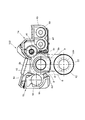
図1は本発明に係るプロセスカートリッジ100の断面図である。
【0017】
また、図6は本発明に係るプロセスカートリッジ100a〜100dを画像形成装置本体に装着した状態を示した断面図である。ここでのa,b,c,dとは周知の画像形成部を並列した画像形成装置におけるイエロー、マゼンタ、シアン、ブラックを示し、説明として必要のない場合は省略することがある。
【0018】
感光体ドラム12はプロセスカートリッジ100のカートリッジ枠体13に、ドラムホルダ2によって回転自在に支持されていて、装置本体に装着された際には図示しない駆動手段によって図中時計回りに回転し、周知の画像形成プロセスに従って画像を形成する(図1には、感光体ドラム12が外れた状態を示してある)。
【0019】
また、プロセスカートリッジ100には現像装置14と帯電装置15とが、カートリッジ枠体13に支持され固定されている。現像装置14の現像容器45と帯電装置15の帯電容器55間は下方に向って転写開口3が設けてある。転写開口3は前フランジ21、後フランジ22を取り付けた感光体ドラム12の長さよりも長手方向で大きい。転写開口3の幅は感光体ドラム12の直径よりも大きい。
【0020】
現像装置14には現像スリーブ41が現像容器45に対して回転可能に支持され、感光体ドラム12と300〜600μm程度の所定のクリアランスを保つような位置に配置されている。現像容器45には、さらにスクリュー42及びスクリュー43が配され、トナーと磁性キャリアとが所定の割合で混合された現像剤を撹拌搬送するようになっている。また、現像ブレード44が、現像スリーブ41とのクリアランスが300〜500μm程度となるように固定されていて、現像剤が現像スリーブ41の表面にコートされる量を規制する。現像スリーブ41は、装置本体に装着された際には図示しない駆動手段によって図中時計回りに回転するとともに高圧電圧が印加され、内部に設けられた磁石に保持された現像剤が感光体ドラム12に対向するニップ部分に搬送され、周知の現像プロセスに供するようになる。
【0021】
帯電装置15には帯電スリーブ51が帯電容器55に対して回転可能に支持され、感光体ドラム12と400〜700μm程度の所定のクリアランスを保つような位置に配置されている。帯電容器55には磁性キャリアからなる帯電剤が収容されている。また、帯電ブレード54が、帯電スリーブ51とのクリアランスが500〜700μm程度となるように固定されていて、帯電剤が帯電スリーブ51の表面にコートされる量を規制する。帯電スリーブ51は、装置本体に装着された際には図示しない駆動手段によって図中時計回りに回転するとともに高圧電圧が印加され、内部に設けられた磁石に保持された帯電剤が感光体ドラム12に対向するニップ部分に搬送され、周知の帯電プロセスに供するようになる。
【0022】
図6において、給紙ローラ206によって搬送された記録媒体である記録紙205は転写ベルト202に吸着されて、イエロー、マゼンタ、シアン、ブラックの各色のプロセスカートリッジ100a〜100dを通過する。イエローのステーションについて代表して説明すると、図示しない露光装置により送られたレーザ光である画像データ201aは感光体ドラム12の表面に潜像を形成し、現像装置14によって現像され、さらには転写ブレード203aで記録紙205に画像が転写される。このプロセスを各ステーションで各色について順次行い、4色の重ね合わせが行われフルカラーのトナー像が形成される。次に、記録紙205は定着装置207を通過しトナー像を定着させ、排紙ローラ208によって機外へ排出される。
【0023】
プロセスカートリッジ100a〜100dは、プロセスカートリッジを支持する支持枠体16(図7参照)の右側板68及び左側板69に夫々取り付けられたアキュライドレール66,67によって装置本体の手前側へ引き出すことが可能である。オペレータがプロセスカートリッジ100を交換する際には、図7に示すように支持枠体16を手前側に引き出した状態で支持枠体16に対してプロセスカートリッジ100の載せ替えを行う。この際、電子写真感光体ドラム12を保持していた保持軸であるドラム軸11は装置本体5側に残されており、支持枠体16を装置本体内に収容することにより、感光体ドラム12及びカートリッジ枠体13が各々独立してドラム軸11に位置決めされる。一方、現像スリーブ41及び帯電スリーブ51は、カートリッジ枠体13に対して図示しないベアリングによって位置決め支持されていて、カートリッジ枠体13がドラム軸11に位置決めされた結果、感光体ドラム12に対して各々前述したようなクリアランスを保って保持されるようになる。
【0024】
図4はプロセスカートリッジ100が装置本体内に収容された状態の断面図であり、図5は非装着状態の断面図である。
【0025】
装置本体の後側板72に設けたベアリング74とベアリング74よりも装置本体奥側に設けた不図示のベアリングでドラム軸11は回転自在に支持され、不図示の駆動源に連結されている。
【0026】
感光体ドラム12の前フランジ21及び後フランジ22の内径がドラム軸11に嵌合し位置決めされる。前フランジ21に設けられた溝部21aはドラム軸11に設けられた突起部11aと係合し、回転方向及び軸方向の移動が規制される。一方、ノブ83の内部に設けた圧縮コイルばねである押圧ばね82によって押しピン81が前フランジ21を図中左方向に押圧し突起部11aとの係合部を固定している。ここで、ドラム軸11の端部には直径をわたって、すり割り溝11eが設けられている。このすり割り溝11eに前フランジ21の内周に設けた突起21eが嵌まり込んでいる。また、すり割り溝11eには押しピン81の先端のヨーク部81eが移動自在に嵌合している。押しピン81の軸部81fはドラム軸11先端の中心穴11fに挿入されていて一部手前側へ突出している。押しピン81のこの突出部には直径をわたって平行ピン81gが打ち込まれている。平行ピン81gの手前側には、押しピン81の軸部81fに座金状のばね座部材81hが嵌合している。ドラム軸11の端部外周に設けた溝11gに先端が係合するフック部83eを有するノブ83が設けてある。ノブ83の穴の底83fとばね座部材81hとの間に押圧ばね82は縮設して押しピン81の軸部81fに挿入されている。
【0027】
プロセスカートリッジ100のカートリッジ枠体13をなす前側板31及び後側板32には各々ベアリング33,34が固定され、夫々がドラム軸11に嵌合しカートリッジ枠体13が装置本体に対して位置決めされている。また、前側板31に設けたピン35が支持枠体16の前側板61の穴に、プロセスカートリッジ100の後側板32に設けたピン36が装置本体の後側板72の穴に夫々嵌合して回り止めをなし、プロセスカートリッジ100のドラム軸11を中心とする回転を防止している。更に、図示しない付勢手段によりプロセスカートリッジ100が図中右側に付勢されることにより、前側板31に設けた突起37が支持枠体16の前側板61に当接し、カートリッジ枠体13のスラスト位置が規制される。これにより、現像装置14及び帯電装置15の感光体ドラム12に対する相対的なスラスト位置関係が所定の位置に定まる。
【0028】
支持枠体16の前側板61にはピン65が設けられ、装置本体の前側板71の穴に嵌合し位置決めされる。一方、支持枠体16の前側板61にはベアリング63が固定され、ドラム軸11の先端を支持している。支持枠体16の後側板62には軸受64が固定されており、ドラム軸11にぶら下がる形になっている。軸受64は、支持枠体16が引き出される際のガイドとしての機能を有していれば良く、軸受64とドラム軸11の嵌め合いはガタが生ずる程度の隙間があっても構わない。この場合には、別途、支持枠体16の後端板62に設けた図示しない位置決めピンを装置本体後側板72に対して嵌合させることが好ましい。
【0029】
一方、プロセスカートリッジ100の前側板31及び後側板32には、ドラムホルダ1及び2が夫々設けられている。
【0030】
ドラムホルダ1及び2は、前側に取り付くか後側に取り付くかのみの違いであり、構成は同一であるため、ここではドラムホルダ2について説明する。感光体ドラム12は感光層を外周に有するアルミ中空のドラム筒の両端にドラムフランジとして前フランジ21、後フランジ22を嵌入固定してある。
【0031】
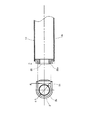
図2は説明のために、ドラムホルダ2の正面図に対して感光体ドラム12の軸方向の断面図を合わせて描いたものである。ドラムホルダ2はドラム支持部2bを有していて、プロセスカートリッジ100が非装着状態の時には、感光体ドラム12をガタを有する状態で保持している。即ち、ドラム支持部2bの内径φDがドラム後フランジ22の先端部22eの外径φdよりも若干大きくなるようにしておく。このガタ量は、プロセスカートリッジ100が装置本体に装着された際の感光体ドラム12と現像スリーブ14e、あるいは感光体ドラム12と帯電スリーブ15eのクリアランスよりも小さく設定してある。例えば、該クリアランスが500μmならば、ガタ量として200μmを設定する。従って、プロセスカートリッジ100が非装着状態の時であってドラム軸11に位置決めがなされていない状態でも、感光体ドラム11が現像スリーブ41あるいは帯電スリーブ51と接触して感光体表面を傷つけてしまうといったことが無い。一方、ガタが存在することにより、ドラムホルダ2の取り付け位置に誤差が生じてしまっても、プロセスカートリッジ100が装置本体に装着された際にドラム後フランジ22とドラム支持部2bが干渉することもない。
【0032】
またドラムホルダ2には、ドラムガイド2aが図1の図中下方向に向って溝状に延設されている。即ち、保持軸であるドラム軸11に対して垂直な方向で転写開口3の方向に内部側から外部側へ向って延設されている。このドラムガイド2aの溝幅Wは、ドラム支持部2bの内径φDよりも狭く、ドラム後フランジ22の先端部22eの外径φdよりもごく僅かに狭くしてあるか、ごく僅かに広くしてあるかの間にある。従って、ドラム後フランジ22の先端部22eはドラムガイド2aを軽く押してドラムガイド2aを通過させて通過できるものの、図1の図中左右方向の移動は規制され、感光体ドラム12を組み込む際の感光体表面が移動する軌跡は、図1の破線A及びBで示した領域に限定される。ゆえに、感光体ドラム12を組み込む際に、挿入開口が狭いにもかかわらず作業者が誤って現像装置14や帯電装置15の構成部品に感光体表面を接触させ傷つけてしまう危険がない。
【0033】
ここで、導電性ブラシ52は、導電性の柔らかい素材で植毛されたものであって、感光体ドラム12を組み込む際に接触したとしても問題は無い。
【0034】
一方、図3に示すようにドラムホルダ2にはドラムストッパー4が取り付けられ、組み込まれた感光体ドラム12が抜けてこないように保持している。
【0035】
図3は、プロセスカートリッジ100を非装着の状態で装置本体の機外の平坦面301においた状態を示している。カートリッジ枠体13の後側板32には脚部32aが設けられている一方、感光体ドラム12はドラムストッパー4によって所定の高さ以下には落ちてこないため、感光体表面が平坦面301に接触することは無い。このドラムストッパー4の固定位置におけるドラムストッパー4に対する後フランジ22の先端部22eのガタ量は、後フランジ22の先端部22eの外径φdに対して、ドラム支持部2bの内径φDが有するのと同等のガタ量である。
【0036】
図3に示すドラムストッパー4はドラムホルダ2のドラムガイド2aの対向面間に圧入されるヨーク状で先端部には夫々外方へ向って逆爪4eが設けられている。この逆爪4eがドラムガイド2aの対向面の溝に嵌入することによってドラムストッパー4の外方への移動を止められている。
【0037】
そこで、ドラムストッパー4は樹脂製であって、ドラムガイド2aの内面に設けた溝に逆爪4eを引っかけて固定してあるため、爪先端をたわませることによって比較的簡単に取り外すことが可能である。従って、プロセスカートリッジ100の寿命よりも早くに感光体ドラム12の交換が必要になった場合には、ドラムストッパー4を取り外して使用済みの感光体ドラム12を抜き去り、新たに感光体ドラム12′をドラムガイド2aに沿って組み込むこともできる。
【0038】
【発明の効果】
上述したように本発明においては、プロセスカートリッジに電子写真感光体ドラムを組み付ける際には、前記ガイド部材に沿って前記電子写真感光体ドラムを挿入することにより、感光体表面に傷を付けることなく電子写真感光体ドラムの組込みが可能となった。
【図面の簡単な説明】
【図1】本発明に係る実施の形態のプロセスカートリッジの縦断面図である。
【図2】ドラムガイドとドラムフランジの寸法関係を説明する図面である。
【図3】プロセスカートリッジを平坦面に置いたときの縦断面図である。
【図4】プロセスカートリッジが装置本体内に収容された状態の水平断面図である。
【図5】プロセスカートリッジが非装着状態の水平断面図である。
【図6】本発明に係る実施の形態の画像形成装置の一部を示す縦断面図である。
【図7】図6の画像形成装置の斜視図である。
【符号の説明】
1…ドラムホルダ
2…ドラムホルダ 2a…ドラムガイド 2b…ドラム支持部
3…転写開口
4…ドラムストッパー 4e…逆爪
5…装置本体
11…ドラム軸 11a…突起部 11e…すり割り溝
12,12′…感光体ドラム
13…カートリッジ枠体
14…現像装置
15…帯電装置
16…支持枠体
21…前フランジ 21a…溝部
22…後フランジ 22e…先端部
31…カートリッジ枠体の前側板
32…カートリッジ枠体の後側板 32a…脚部
33…ベアリン
34…ベアリング
35…ピン
37…突起
41…現像スリーブ
42…スクリュー
43…スクリュー
44…現像ブレード
45…現像容器
51…帯電スリーブ
52…導電性ブラシ
54…帯電ブレード
55…帯電容器
61…支持枠体の前側板
62…支持枠体の後側板
63…ベアリング
64…軸受
65…ピン
66…アキュライドレール
67…アキュライドレール
68…右側板
69…左側板
71…装置本体の前側板
72…装置本体の後側板
74…ベアリング
81…押しピン 81e…ヨーク部 81f…軸部 81g…平行ピン 81h…ばね座部材
82…押圧ばね
83…ノブ
100…プロセスカートリッジ 100a〜100d…プロセスカートリッジ
201a…画像データ
202…転写ベルト
203a…転写ブレード
205…記録紙
206…給紙ローラ
207…定着装置
208…排紙ローラ
301…平坦面[0001]
BACKGROUND OF THE INVENTION
The present invention relates to an electrophotographic apparatus such as a copying machine, a printer, a recorded image display apparatus, and a facsimile machine that develops an electrostatic latent image formed on an image carrier by an electrophotographic system, an electrostatic recording system, and the like to form a visible image. The present invention relates to a process cartridge and an assembling method thereof in an image forming apparatus.
[0002]
Here, the electrophotographic image forming apparatus forms an image on a recording medium using an electrophotographic image forming system. Examples of the electrophotographic image forming apparatus include an electrophotographic copying machine, an electrophotographic printer (for example, a laser beam printer, an LED printer, etc.), a facsimile machine, a word processor, and the like.
[0003]
The process cartridge is a cartridge in which a charging unit, a developing unit or a cleaning unit and an electrophotographic photosensitive drum are integrally formed, and the cartridge can be attached to and detached from the image forming apparatus main body. In addition, at least one of the charging unit, the developing unit, and the cleaning unit and the electrophotographic photosensitive drum are integrally formed into a cartridge that can be attached to and detached from the main body of the image forming apparatus. Further, it means that at least the developing means and the electrophotographic photosensitive drum are integrally formed into a cartridge so as to be detachable from the apparatus main body.
[0004]
[Prior art]
Conventionally, in this type of image forming apparatus, a consumable part such as a photosensitive drum is configured to be replaceable by an operator, and when the life of the image forming apparatus reaches the end of life, the operator replaces it with a new one. An image with stable quality can be obtained.
[0005]
On the other hand, as a developing device, a two-component developing device using a developer in which toner particles and a magnetic carrier are mixed at a certain ratio is used because of a demand for high-quality image quality. In the two-component development method, the magnetic carrier deteriorates due to durability and the quality of the image deteriorates.Therefore, only the developer has been exchanged, but the development device itself has to be replaced to improve the efficiency of maintenance work. It has come to be configured to be replaced as a consumable part.
[0006]
Further, in an image forming apparatus using an electrophotographic image forming process, the electrophotographic photosensitive member and the process means acting on the electrophotographic photosensitive member are integrally formed into a cartridge, and the cartridge can be attached to and detached from the image forming apparatus main body. The process cartridge method is adopted. According to this process cartridge system, the apparatus can be maintained by the user himself / herself without depending on the service person, so that the operability can be remarkably improved. Therefore, this process cartridge system is widely used in image forming apparatuses.
[0007]
In such a process cartridge, it is necessary to keep a fine gap between the surface of the developing sleeve and the surface of the photosensitive member at a high precision in order to maintain good development characteristics. Therefore, conventionally, a roller having a larger diameter than that of the developing sleeve is provided at both ends in the axial direction of the developing sleeve, and the roller is abutted against the surface of the photosensitive drum so as to maintain a space.
[0008]
However, in the configuration in which the spacer roller is in contact, vibration generated when the developing sleeve is driven is transmitted to the photosensitive drum, which causes various image defects. Therefore, the image forming apparatus main body is provided with a support shaft for pivotally supporting the photosensitive drum, and when the process cartridge is mounted on the apparatus main body, the photosensitive drum and the developing device are respectively positioned with respect to the support shaft so that the high accuracy In order to maintain the interval, a configuration has been adopted (see Japanese Patent Application Laid-Open No. 07-077849).
[0009]
The process cartridge having such a configuration is particularly effective in improving color unevenness and color misregistration for a full-color image forming apparatus that performs color matching using a plurality of process cartridges.
[0010]
[Problems to be solved by the invention]
In the process cartridge having the above-described configuration, the position of the photosensitive drum is not determined when the process cartridge is not attached to the apparatus main body, so that the surface of the photosensitive member may come into contact with the surface of the developing sleeve or the like. In recent years, along with miniaturization of the main body of the apparatus, the process cartridge itself has also been miniaturized, and the photosensitive drum is provided in a very small space. In particular, the assembly of the photosensitive drum so that it does not come into contact with other parts during assembly It has become very difficult.
[0011]
[Means for Solving the Problems]
In order to solve the above-described problems, the present invention provides an electrophotographic photosensitive drum, a charging member that carries a carrier and is disposed in non-contact with the drum, and a charging member that charges the electrophotographic photosensitive drum, and a carrier And a developing means for developing an electrostatic latent image formed on the electrophotographic photosensitive drum, and having a developing sleeve disposed in a non-contact manner with the drum, and the electrophotographic photosensitive drum A process cartridge that can be attached to and detached from an image forming apparatus main body having a holding shaft into which the electrophotographic photosensitive drum can be inserted and removed.
The support member is provided with a flange holding portion that holds a flange of the electrophotographic photosensitive drum, and a guide portion that is continuous with the flange holding portion and guides attachment / detachment of the electrophotographic photosensitive drum across the flange. The gap between the guide portions is smaller than the outer diameter of the flange, the gap between the flange support portions is larger than the outer diameter of the flange, and the clearance between the flange and the flange support portion is determined by the process cartridge. The image forming apparatus main body is set to be smaller than a clearance between the developing sleeve and the electrophotographic photosensitive drum and smaller than a clearance between the charging sleeve and the electrophotographic photosensitive drum. .
[0016]
DETAILED DESCRIPTION OF THE INVENTION
FIG. 1 is a cross-sectional view of a
[0017]
FIG. 6 is a cross-sectional view showing a state in which the
[0018]
The
[0019]
Further, a developing
[0020]
A developing
[0021]
A charging
[0022]
In FIG. 6, the
[0023]
The
[0024]
FIG. 4 is a cross-sectional view of the
[0025]
The drum shaft 11 is rotatably supported by a
[0026]
The inner diameters of the
[0027]
[0028]
A
[0029]
On the other hand,
[0030]
Since the
[0031]
For the sake of explanation, FIG. 2 shows a sectional view in the axial direction of the
[0032]
In the
[0033]
Here, the
[0034]
On the other hand, as shown in FIG. 3, a drum stopper 4 is attached to the
[0035]
FIG. 3 shows a state in which the
[0036]
The drum stopper 4 shown in FIG. 3 has a yoke shape that is press-fitted between the opposing surfaces of the
[0037]
Therefore, the drum stopper 4 is made of resin and is fixed by hooking the reverse claw 4e in the groove provided on the inner surface of the
[0038]
【The invention's effect】
As described above, in the present invention, when the electrophotographic photosensitive drum is assembled to the process cartridge, the electrophotographic photosensitive drum is inserted along the guide member, so that the surface of the photosensitive member is not damaged. An electrophotographic photosensitive drum can be incorporated.
[Brief description of the drawings]
FIG. 1 is a longitudinal sectional view of a process cartridge according to an embodiment of the present invention.
FIG. 2 is a diagram illustrating a dimensional relationship between a drum guide and a drum flange.
FIG. 3 is a longitudinal sectional view when a process cartridge is placed on a flat surface.
FIG. 4 is a horizontal sectional view showing a state in which a process cartridge is accommodated in the apparatus main body.
FIG. 5 is a horizontal sectional view of a process cartridge that is not attached.
FIG. 6 is a longitudinal sectional view showing a part of the image forming apparatus according to the embodiment of the present invention.
7 is a perspective view of the image forming apparatus in FIG. 6. FIG.
[Explanation of symbols]
DESCRIPTION OF
Claims (7)
前記支持部材には前記電子写真感光体ドラムのフランジを保持するフランジ保持部と、前記フランジ保持部に連続しており前記フランジを挟んで前記電子写真感光体ドラムの着脱を案内するガイド部が設けられ、前記ガイド部間の間隔は前記フランジの外径よりも小さく、前記フランジ支持部の間隔は前記フランジの外径よりも大きく、
前記フランジと前記フランジ支持部のクリアランスは、前記プロセスカートリッジが前記画像形成装置本体に装着された状態で、前記現像スリーブと前記電子写真感光体ドラムのクリアランスより小さく、前記帯電スリーブと前記電子写真感光体ドラムのクリアランスより小さいように設定されることを特徴とするプロセスカートリッジ。An electrophotographic photosensitive drum, a charging sleeve that carries a carrier and is disposed in non-contact with the drum , a charging member that charges the electrophotographic photosensitive drum, and a carrier that is disposed in non-contact with the drum. has a developing means for developing the electrostatic latent image formed on the developing sleeve having the electrophotographic photosensitive member drum, a support member for supporting and loosely fitted to said electrophotographic photosensitive drum, the that the In a process cartridge that can be attached to and detached from an image forming apparatus main body having a holding shaft into which an electrophotographic photosensitive drum can be inserted and removed,
Wherein the flange holding portion for holding a flange of said electrophotographic photosensitive drum to the support member, the guide portion for guiding the attachment and detachment of said electrophotographic photosensitive drum across the flange is continuous with the flange holding section provided is the spacing between the guide portion the small fence than the outer diameter of the flange, distance of the flange support portion is larger than the outer diameter of the flange,
The clearance between the flange and the flange support portion is smaller than the clearance between the developing sleeve and the electrophotographic photosensitive drum in a state where the process cartridge is mounted on the image forming apparatus main body, and the charging sleeve and the electrophotographic photosensitive member. A process cartridge which is set to be smaller than a clearance of a body drum .
Priority Applications (1)
| Application Number | Priority Date | Filing Date | Title |
|---|---|---|---|
| JP2000170481A JP4630421B2 (en) | 2000-06-07 | 2000-06-07 | Process cartridge |
Applications Claiming Priority (1)
| Application Number | Priority Date | Filing Date | Title |
|---|---|---|---|
| JP2000170481A JP4630421B2 (en) | 2000-06-07 | 2000-06-07 | Process cartridge |
Publications (3)
| Publication Number | Publication Date |
|---|---|
| JP2001350393A JP2001350393A (en) | 2001-12-21 |
| JP2001350393A5 JP2001350393A5 (en) | 2007-07-19 |
| JP4630421B2 true JP4630421B2 (en) | 2011-02-09 |
Family
ID=18673194
Family Applications (1)
| Application Number | Title | Priority Date | Filing Date |
|---|---|---|---|
| JP2000170481A Expired - Fee Related JP4630421B2 (en) | 2000-06-07 | 2000-06-07 | Process cartridge |
Country Status (1)
| Country | Link |
|---|---|
| JP (1) | JP4630421B2 (en) |
Families Citing this family (5)
| Publication number | Priority date | Publication date | Assignee | Title |
|---|---|---|---|---|
| JP4488786B2 (en) * | 2004-04-28 | 2010-06-23 | 京セラミタ株式会社 | Image forming apparatus |
| KR100633070B1 (en) | 2004-12-14 | 2006-10-11 | 삼성전자주식회사 | Developing apparatus |
| JP4872464B2 (en) * | 2006-05-31 | 2012-02-08 | ブラザー工業株式会社 | Image forming apparatus |
| JP5081547B2 (en) * | 2007-09-10 | 2012-11-28 | 株式会社リコー | Image forming apparatus and process cartridge |
| JP5282061B2 (en) * | 2010-03-23 | 2013-09-04 | 京セラドキュメントソリューションズ株式会社 | Image forming apparatus |
Citations (4)
| Publication number | Priority date | Publication date | Assignee | Title |
|---|---|---|---|---|
| JPS6388874U (en) * | 1986-11-27 | 1988-06-09 | ||
| JPH01237588A (en) * | 1987-11-27 | 1989-09-22 | Ricoh Co Ltd | Image carrying body handling device |
| JPH04321069A (en) * | 1991-04-22 | 1992-11-11 | Minolta Camera Co Ltd | Image forming device |
| JPH0792883A (en) * | 1993-09-22 | 1995-04-07 | Oki Electric Ind Co Ltd | Electrophotographic recording device |
Family Cites Families (1)
| Publication number | Priority date | Publication date | Assignee | Title |
|---|---|---|---|---|
| JPS6388874A (en) * | 1986-10-01 | 1988-04-19 | Sumitomo Electric Ind Ltd | Package of semiconductor device |
-
2000
- 2000-06-07 JP JP2000170481A patent/JP4630421B2/en not_active Expired - Fee Related
Patent Citations (4)
| Publication number | Priority date | Publication date | Assignee | Title |
|---|---|---|---|---|
| JPS6388874U (en) * | 1986-11-27 | 1988-06-09 | ||
| JPH01237588A (en) * | 1987-11-27 | 1989-09-22 | Ricoh Co Ltd | Image carrying body handling device |
| JPH04321069A (en) * | 1991-04-22 | 1992-11-11 | Minolta Camera Co Ltd | Image forming device |
| JPH0792883A (en) * | 1993-09-22 | 1995-04-07 | Oki Electric Ind Co Ltd | Electrophotographic recording device |
Also Published As
| Publication number | Publication date |
|---|---|
| JP2001350393A (en) | 2001-12-21 |
Similar Documents
| Publication | Publication Date | Title |
|---|---|---|
| US7366441B2 (en) | Method and apparatus for image forming having a predetermined gap formed between an image bearing member and a developing member | |
| EP1202135B1 (en) | Process cartridge, load producing member and electrophotographic image forming apparatus | |
| US8160478B2 (en) | Process cartridge and image forming apparatus | |
| JP3315560B2 (en) | Process cartridge, electrophotographic image forming apparatus, and method of mounting electrophotographic photosensitive drum | |
| US7068965B2 (en) | Developing cartridge, side cover mounting method and electrophotographic image forming apparatus | |
| EP0822469B1 (en) | Process cartridge and image forming apparatus to which process cartridge can detachably be mounted | |
| US9188945B2 (en) | Cartridge and image forming apparatus | |
| JP3684195B2 (en) | Process cartridge and electrophotographic image forming apparatus | |
| EP0549400A2 (en) | Developing apparatus and process cartridge having same | |
| JP2004012523A (en) | Developing device, developing cartridge, process cartridge, and image forming apparatus | |
| JP2006091652A (en) | Cartridge, process cartridge and electrophotographic image forming apparatus | |
| US6671477B2 (en) | Developing device, process cartridge and image forming apparatus | |
| KR100338203B1 (en) | Developing apparatus | |
| JP2002189401A (en) | Process cartridge and electrophotographic image forming device | |
| JP4630421B2 (en) | Process cartridge | |
| US6654583B2 (en) | Developing apparatus | |
| JP3608767B2 (en) | Image forming apparatus | |
| US6952543B2 (en) | Image forming apparatus, process cartridge, and electrode member | |
| JP2603117B2 (en) | Multicolor image forming device | |
| JP2006337725A (en) | Process cartridge and electrophotographic image forming apparatus | |
| US11467528B2 (en) | Universal coupler with coupler holder and driving coupler elastically combined with each other | |
| JPH06130799A (en) | Developing device | |
| KR0123924B1 (en) | Process cartridge and image forming system on which process cartridge is mountable | |
| JP7001353B2 (en) | Image forming device | |
| JP2006039139A (en) | Process cartridge and image forming apparatus |
Legal Events
| Date | Code | Title | Description |
|---|---|---|---|
| RD01 | Notification of change of attorney |
Free format text: JAPANESE INTERMEDIATE CODE: A7421 Effective date: 20060106 |
|
| A521 | Written amendment |
Free format text: JAPANESE INTERMEDIATE CODE: A523 Effective date: 20070601 |
|
| A621 | Written request for application examination |
Free format text: JAPANESE INTERMEDIATE CODE: A621 Effective date: 20070601 |
|
| RD04 | Notification of resignation of power of attorney |
Free format text: JAPANESE INTERMEDIATE CODE: A7424 Effective date: 20100201 |
|
| A977 | Report on retrieval |
Free format text: JAPANESE INTERMEDIATE CODE: A971007 Effective date: 20100308 |
|
| A131 | Notification of reasons for refusal |
Free format text: JAPANESE INTERMEDIATE CODE: A131 Effective date: 20100316 |
|
| A521 | Written amendment |
Free format text: JAPANESE INTERMEDIATE CODE: A523 Effective date: 20100517 |
|
| RD01 | Notification of change of attorney |
Free format text: JAPANESE INTERMEDIATE CODE: A7421 Effective date: 20100630 |
|
| TRDD | Decision of grant or rejection written | ||
| A01 | Written decision to grant a patent or to grant a registration (utility model) |
Free format text: JAPANESE INTERMEDIATE CODE: A01 Effective date: 20101109 |
|
| A01 | Written decision to grant a patent or to grant a registration (utility model) |
Free format text: JAPANESE INTERMEDIATE CODE: A01 |
|
| A61 | First payment of annual fees (during grant procedure) |
Free format text: JAPANESE INTERMEDIATE CODE: A61 Effective date: 20101115 |
|
| FPAY | Renewal fee payment (event date is renewal date of database) |
Free format text: PAYMENT UNTIL: 20131119 Year of fee payment: 3 |
|
| R150 | Certificate of patent or registration of utility model |
Free format text: JAPANESE INTERMEDIATE CODE: R150 |
|
| LAPS | Cancellation because of no payment of annual fees |