JP4628637B2 - Biopsy equipment - Google Patents
Biopsy equipment Download PDFInfo
- Publication number
- JP4628637B2 JP4628637B2 JP2001577847A JP2001577847A JP4628637B2 JP 4628637 B2 JP4628637 B2 JP 4628637B2 JP 2001577847 A JP2001577847 A JP 2001577847A JP 2001577847 A JP2001577847 A JP 2001577847A JP 4628637 B2 JP4628637 B2 JP 4628637B2
- Authority
- JP
- Japan
- Prior art keywords
- blade
- tissue
- biopsy device
- blades
- biopsy
- Prior art date
- Legal status (The legal status is an assumption and is not a legal conclusion. Google has not performed a legal analysis and makes no representation as to the accuracy of the status listed.)
- Expired - Fee Related
Links
Images


Classifications
-
- A—HUMAN NECESSITIES
- A61—MEDICAL OR VETERINARY SCIENCE; HYGIENE
- A61B—DIAGNOSIS; SURGERY; IDENTIFICATION
- A61B10/00—Other methods or instruments for diagnosis, e.g. instruments for taking a cell sample, for biopsy, for vaccination diagnosis; Sex determination; Ovulation-period determination; Throat striking implements
- A61B10/02—Instruments for taking cell samples or for biopsy
- A61B10/0233—Pointed or sharp biopsy instruments
- A61B10/0266—Pointed or sharp biopsy instruments means for severing sample
-
- A—HUMAN NECESSITIES
- A61—MEDICAL OR VETERINARY SCIENCE; HYGIENE
- A61B—DIAGNOSIS; SURGERY; IDENTIFICATION
- A61B10/00—Other methods or instruments for diagnosis, e.g. instruments for taking a cell sample, for biopsy, for vaccination diagnosis; Sex determination; Ovulation-period determination; Throat striking implements
- A61B10/02—Instruments for taking cell samples or for biopsy
- A61B2010/0208—Biopsy devices with actuators, e.g. with triggered spring mechanisms
Abstract
Description
【0001】
本発明は一般的に、ヒト及び動物の組織から生検試料を採取する装置及び方法に係る。より詳細には、本発明は、リンパ節組織といった軟組織の採取における改善に係る。
【0002】
医療及び外科的な実施において、軟組織の生検採取は一般的であり、且つ、重要な検査である。生検試料は一般的に、中空の丸い針又はカニューレ設計に基づいた生検装置を使用して得られる。その結果、円筒状の組織のセクションが採取される。この生検装置は、組織の奥深くまで入ることができるが、しばしば採取される試料は細いか又は小さく、これは正確な診断を下すことが困難になる。更に、生検試料が円筒状でなければならない理由は本質的にはない。というのは、組織病理学者は、試料を一般的に0.004ミリメートルの厚さを有する非常に薄いセクション又はスライスに切断し、その後、切断されたセクション又はスライスを次なる染色及び顕微鏡検査のためにガラスのスライドに載せて試料を処理するからである。従って、円筒状の試料は、その非常に小さな一部の組織のみが検査されるので、無駄が多くなってしまう。更に、円筒状の装置によってできる傷は、その傷の側面が互いにくっつきにくいので出血し易い。
【0003】
同様の問題がリンパ節生検の専門分野においても発生する。リンパ節は、感染、又は、腫瘍による浸潤によって表在領域において拡大し、一般的に、診断を行うにはリンパ節検査が必要となる。針によってリンパ節を吸入することにより、細胞学的検査を行うための細胞を採取することはできるが、この技法は一般的に良性状態と悪性状態とを識別するには有用ではあるが、特に、悪性腫瘍があると思われる場所を決定するための完全な診断はすることができない。従来の円筒状の生検針を使用して、患者の一部における拡大したリンパ節の診断を得ることも可能ではあるが、得られる試料は細く、組織病理学者が完全な診断を下すのは困難となる。特に、点在する異常性を見逃してしまう場合があり、また、リンパ節の構造を容易に確認することができない場合がある。多くの組織病理学者は、完全なリンパ節(1乃至5センチメートルの直径に達するもの)が摘出できる開リンパ節切除法を推奨している。このリンパ節切除法は、患者を必要以上の外科的処置にさらす(一般的にリンパ節の非常に薄いスライスが検査されるのに比較して)ことになり、また、手術は一般的に、局部麻酔ではなく全身麻酔で行われる。全身麻酔は、患者及び医者に対し不便さをかなり増加し、また、患者に対する危険性を増加し、それにより、診断を下すのが遅れ、処置にかかる費用が増加するので、回避されることが望ましい。
【0004】
これらの問題の一部に対処しようとする生検装置が、US3,800,783 Jamshidiから公知である。この文献には、テーパにされた切断遠位端を有する略矩形のブレードと、覆い被さるようにある試料固定刺を有するフックを形成し、ブレードに設けられた後方に向けられるスロットを含む筋生検装置が説明される。試料がスロット内に捕捉された後、ブレードの上にシースが被せられ、生検装置を引出す際に試料が保護される。しかし、この装置は、実施の際に幾つかの問題がある。例えば、フックの先端は、刺が正しい点において試料組織と係合するために採取されるべき組織より奥に挿入されなければならず、また、フック型の設計は採取される生検試料は比較的小さい点である。
【0005】
この問題を対処するもう1つの試みが、US4,926,877 Bookwalterに説明され、この文献には、大部分が従来と同様ではあるが、側部が平たくされたカニューラと、生検試料の端を周りの組織から切り離す為の伸張可能で且つ弾性のあるブレードを有する装置が開示される。しかし、この装置は依然として上述したような従来の設計に関連した同様の欠点を有する。
【0006】
FR2,493,137に、皮膚試料を得るためにパラレルブレードが設けられた生検装置が説明される。しかし、この装置では、ブレードは1乃至3ミリメートルの深さまで入り、最大で5マイクロメートル離され、また、ブレードは組織試料を切断するよう互いに向けて曲げられている。従って、この装置の有用性は非常に限られている。
【0007】
他の様々な種類の生検装置は、US4,971,067、US4,168,698、EP0919192A、EP0235489A、US4832045、WO93/19675、及び、GB1,084,640に説明される。
【0008】
従って、現行より大きい寸法の試料を採取することができ、更に、より平たく、従って、公知の装置で入手可能であるものよりもより効率的なセクションである生検試料を採取することができる改善された生検装置が必要である。
【0009】
本発明では、組織採取器を含む生検装置を提供する。組織採取器は、向かい合わせに配置され、互いに略平行であり、略平らである1対のブレードと、生検装置が挿入された後に、組織から組織試料を切り離す切断手段とを含む。1対のブレードは、採取されるべき組織を受容する空間の2つの面を画成する。1対のブレードは、生検装置の先端において、装置が組織に挿入されるに従って採取されるべき試料を切断する前縁部を有する。
【0010】
本発明の第2の面によると、略平行なツインブレードと、略平行なツインブレードに沿って摺動可能に前進するよう構成される切離しブレードを含む生検装置を提供する。略平行なツインブレードは組織内に入れられると、略平行なツインブレード間で組織生検試料の薄い平らなセクションを切断する。切離しブレードは、略平行なツインブレードに沿って摺動可能に前進して、組織生検試料の少なくとも遠位端を切り取る。
【0011】
本発明のもう1つの面によると、向かい合わせに配置され、互いに略平行であり、略平らである1対のブレードを含む組織採取器を提供する。1対のブレードは、採取されるべき組織を受容する空間の2つの面を画成する。1対のブレードは、生検装置の先端において、生検装置が組織に挿入されるに従って採取されるべき試料を切断する前縁部を有する。1対のブレードは、互いに対し可動である第1のブレード及び第2のブレードを含む。
【0012】
本発明の更なる面によると、略平行なツインブレードを含む生検装置を提供する。略平行なツインブレードは、組織面を通るよう前進されると、略平行なツインブレード間で組織生検試料の薄い平らな一部を切断する。この生検装置は、ツインブレードの各ブレードが別々に前進するよう構成される。
【0013】
本発明は更に、生検試料を採取する方法を提供する。本発明の方法は、i)生検装置を、採取されるべき組織内に挿入して、生検試料の上端面と下端面を切断する段階と、ii)生検装置を使用して、生検試料の側端面を切断する段階とを含む。
【0014】
本発明は更に、本発明の生検装置と、キャリア媒体上の命令との組合せを提供する。命令は、生検試料を採取する方法を説明する。生検試料を採取する方法は、生検装置を、採取されるべき組織内に挿入して、生検試料の上端面と下端面を切断する段階と、生検装置を使用して、生検試料の少なくとも1つの側端面切断する段階とを含む。
【0015】
生検装置が挿入されるに従い、採取されるべき組織を切断する前縁部を有する向かい合わせに配置される1対のブレードを使用することにより、周りの組織から比較的大きく且つ平らな組織試料を切断する生検装置を提供することが可能である。従って、本発明の生検装置は、完全且つ効率のよい組織学的検査を行うのに十分な寸法を有する組織のセクションを提供し、その一方で、患者の傷を最小限にし、処理後の出血の可能性を低くすることができる。組織採取器のブレードは、互いに別個又は互いから識別されることが好適である。2つのブレードは、組織を受容するための大きい空間を画成し、周りの組織に対し影響をほとんど与えないように構成され、最適な大きさを有する試料を容易に得ることを可能にする。本発明は更に、単純且つ安価で製造でき、簡単に動作することのできる生検装置の構成を可能にする。
【0016】
本発明の生検装置は、軟組織に挿入されるとき、2つの鋭くされたブレードは、2つのブレード間で組織試料のスライス又はセクションを、試料を傷めることなく切断することができるという認識に基づいている。本発明の生検装置は、生きている又は死んでいるヒト又は動物の皮膚、肝臓、腎臓、又は、腫瘍組織といった軟組織を病理学的な研究のために採取するよう使用されうる。本発明の装置は特に、患者に集中的又は異例な外科処置が施される必要なく、及び、人体に大きい開口を形成する必要なく、例えば、拡大したリンパ節といった表在領域からの試料を得るのに適している。
【0017】
比較的大きく且つ平らな生検試料の収集は、関連技術の一般的に円筒状である組織試料に比べて多数の利点を有する。生検試料の形状が、試料の検査の責任者である組織病理学者によって所望される形状により適合するので、試料のより大きい部分が分析可能である。即ち、構造的な又は点在する異常性を検出する可能性が大きくなる。なぜなら、より大きい連続する表面領域が検査され、正しい診断を行うのを支援するからである。また、組織採取器のブレードによりつけられる傷の2つの表面は、外部から圧力を加えることにより容易にくっつくので出血の可能性も低くなる。大きい検査試料を入手する必要があり、特に、関心の組織が表在性であるか又は容易に到達することが可能である(例えば、観血療法又は死後検査時)場合に特に有利である。
【0018】
軟組織用の一般的な生検装置は、約1ミリメートルの内径を有するカニューレを有する。大きい直径を有する装置は、最大で2.5ミリメートルの試料を提供する場合もある。試料の長さは一般的に1乃至2センチメートルである。これらと比較して、本発明の実施例は、3乃至15ミリメートルの幅と、1乃至2ミリメートルの厚さと、1乃至3センチメートルの長さを有する試料を容易に提供することができる。本発明の好適な実施例では、約4ミリメートルの幅と、1ミリメートルの厚さを有する試料を提供するが、これらの値は、特定の適用の要件に合わせて容易に調節することができる。例えば、1センチメートル以下の長さ、及び/又は、1ミリメートル以下(最小約0.5ミリメートル)の厚さを有する小さい試料も、実際にはこのように小さい試料はほどんど必要ではないが、提供することができる。
【0019】
組織を受容する空間は、1つの又は両方の側面に沿って開いていることが好適である。従って、ブレードには、ブレードの平面に対し略垂直に延在し、それぞれ向かい合わせにされる縁部が設けられる。それにより、組織を受容する空間に、1つ又は2つの長手方向の開口が画成される。これは、従来のカニューレタイプの装置において側壁が生検試料を取り囲む場合よりもかなり薄いセクションを切断することを可能にするので有利である。生検装置が最初に挿入されると、採取される組織は、開口部分において周りの組織とつながった状態に保たれ、これにより、採取される組織は支持され、より品質のよい試料が提供される。このことは特に、採取される組織が繊維質である場合に、生検装置の挿入時に側面において組織が保持されることが有用である。装置を挿入した後に、試料の側面は、従来の外科的手段又は生検装置の機械的構造によって、以下に詳細に説明するように、周りの組織から切り離される。
【0020】
ブレードは、互いに略平行であり、平らであることが好適である。このことは、生検装置内において大きく且つ平らな組織試料を固定することを支援し、採取されるべき組織への損傷を少なくする。
【0021】
好適な実施例では、生検装置の1対のブレードは同時に挿入される。1対のブレードをステンレススチールから製造することにより、採取されるべき組織内に単純に手動で押されて入るのに必要な要求される鋭さと剛性を有するブレードを形成可能であることが分かっている。しかし、切断するのが特に困難である組織の場合、ブレードは、互いに対し順次挿入することができるよう可動であるよう形成されることも可能であり、従って、1対のブレードは互いに対し、振動する又は揺動する(或いは、両方のブレードはタンデムに揺動するようにされてもよい)。このような生検装置の変形の1つにおいて、ブレードは、互いに対し、小さくハサミのように開閉する動作を行うようピボットする。ブレードは、モータ又はバイブレータによって高い振動数で駆動されることが好適である。ブレードは、例えば、電気発振器又は超音波振動子を使用して超音波周波数で駆動されることが有利である。
【0022】
ブレードは、生検装置を採取されるべき組織内に挿入し易くするために生検装置の先端に向かって細くされることが好適である。このように細くされることにより、以下に説明するように、周囲の組織から組織試料の端を切断し易くする。好適な実施例では、ブレードは点となるよう細くされる。
【0023】
生検装置は更に、生検装置が挿入された後に、組織から生検試料を切断する切断手段を含むことが有利である。これにより、試料を周囲の組織から段階的に切断することを可能にする。即ち、最初に試料の上面及び下面が切断され、次に、周囲の組織につながっている残りの点が切断される。これにより、生検試料の形態が保たれ易くなるので、より大きい使用可能な試料が提供される。このことは更に、生検装置を挿入する度に、有用な試料が得易くなるので、費用及び時間を節約でき、患者の不快感を軽減することができる。
【0024】
切断手段は、組織を受容する空間の側面に沿って切断することが好適である。1つの実施例では、切断手段は、ブレードの面に対し略垂直に切断する。切断手段は、装置の先端に隣接する組織から試料の端を切断することが好適である。好適な構成では、このことは、生検装置上に試料切離しブレードを摺動可能に取り付け、組織採取器の向かい合わせに配置されたブレードのどちらの側面も切断することにより達成される。試料の端を切断するには、切離しブレードの一部は弾力があり、切離しブレードが前進されるに従い、生検装置の先端の周りで内側に曲がるようにされることが好適である。このことは、2つの向かい合わせに配置されたブレードの先端に向かって曲がるよう付勢されるスプラング切断延長部を有するブレードガイドをその両側に取付けられるキャリッジを設けることにより達成できる。この実施例において、切離しブレードの切断部の要求される弾力による付勢は、切断延長部を、スプラングニッケルチタン合金から形成することにより達成しうる。このような構成により、試料切離しブレードのスプラング延長部は、試料の側面及び端部が切断された後に、生体検査の先端の周りで曲がり、生検装置が引出される際に、試料を保護し且つ固定することを支援する。
【0025】
別の実施例において、別個の試料切離しブレードが、2つの向かい合わせに配置される1次ブレードのどちらかの側面に沿って前進される。追加として、又は、代替として、1次ブレードの上面に切断ブレードが挿入されて試料の先端を切断することも可能である。この切断ブレードには、1次ブレードの側面に沿って切断するよう各側部に切断延長部が設けられうる。
【0026】
切離しブレードは作動手段に接続され、組織から試料を切断するよう制御可能であることが好適である。1つの実施例では、作動手段は、生検装置上の、ガイドスロットに沿って動作するボタンに接続されることにより、生検装置が挿入された後に、試料切離しブレードが前進される。作動手段は、キャリッジを生検装置の先端から離すよう弾力があるように付勢されうる。生検装置は、片手で動作させるのに適していることが好適であり、例えば、試料切離しブレードを動作させるピストルグリップ及びトリガを有しうる。
【0027】
特に好適な実施例において、リンパ節生検装置は、平行な面において向かい合わせに置かれるツインブレードを有する。ツインブレードは、組織への貫入を支援するために鋭くされた先端を有する。リンパ節生検装置は更に、内側に曲げられ、弾力があり、鋭くされた遠位先端を有する切離しブレードを有する。切離しブレードは、トラックによって、ツインブレードに沿って摺動可能に動くことができ、それにより、切離しブレードが引き込められた位置では、ツインブレードのみが採取されるべき試料に対し露出しており、ツインブレードを組織に当てて、生検試料の上面と下面を切断することができる。切離しブレードを前進させることにより、生検試料の側壁と遠位端を切断することができる。ツインブレード及び切離しブレードは、a)外科医の手に好都合に嵌る寸法を有するハンドルに固定することが可能である。より具体的には、ツインブレードはハンドルに取付けられ、切離しブレードはボタンに取付けられ、ボタンをトラックに沿って前後に動かすことにより、切離しブレードがツインブレードに沿って前後に動かされる。或いは、ツインブレード及び切離しブレードは、b)ハンドル、トリガ、押し棒、及び、バレルを有する銃状の装置に固定することが可能である。ツインブレードは、バレルの端に取付けられる。この構成では、切離しブレードは、引き込められた位置にあるときは、バレル内にあることが好適である。押し棒を、バレル内のトラックに沿って前進させる(トリガに圧力を加えることにより達成される)と、切離しブレードは、ツインブレードの側部に沿ってバレルの外へ出るよう前進される。従って、ツインブレードの間で優しく圧縮され挟まれることにより、生検試料が固定されると、切離しブレードの先端は、生検試料の側壁と遠位端を切断する。完全に前に出された位置では、切離しブレードの先端は、ツインブレードの遠位端に重なる。銃の本体内には、トリガに圧力を加えることにより、切離しブレードを前進させ、バネを伸張させ、また、トリガへの圧力を解除することにより、バネを元に戻し、切離しブレードを引込ませる機械的又は電気機械的手段を与えるレバー、ピボット、バネ、又は、他の同様の構成が配置される。
【0028】
本発明の上述した面及び他の面は、添付図面を参照しながら、例示的に以下に説明する。
【0029】
最初に図1A乃至図1Fを参照するに、これらの図面は、組織採取器の向かい合わせに配置される1対の1次ブレード1を示す。1次ブレードは、試料を受容する容積又は空間の上面及び底面は画成する。各1次ブレードの端は、点となるようテーパにされる鋭くされたエッジ2を有する。先端における点について成される角度は、切り取って調べられる組織に応じて選択され得る。一般的には、30°乃至60°の角度であり、約45°が好適である。エッジ2は、切り取って調べられる軟組織に容易に貫入し易いよう十分に鋭くあるべきである。向かい合わせに配置される1次ブレード1は、ハンドル(図1には図示せず)に取付けられ、所望される場合には、違う組織に対し異なるブレードセットを使用する、及び/又は、消毒又は使用後に処分することを容易にすることができるよう取替え可能であるよう構成され得る。
【0030】
図1G乃至図1Lは、試料切離しブレード9のバージョンを示す。図1H及び図1Iに示すように、切離しブレード9は、1対の1次ブレード1の上に合わせられ、タブ3によって1次ブレードの裏面まで回り込んで挟む側面切断ブレード又はブレードガイド部5が取付けられる。各ブレードガイド部5は弾性のある切断延長部4を有する。延長部4は、1次ブレードの側縁に接触する。延長部4は、1次ブレード1間の試料受容容積に向かって内側に付勢されるよう構成される。これは、例えば、自然に内側に曲がるよう延長部4を構成することにより実現される。このようにすると、図1Hに示すように試料切離しブレードが引込まれた状態では、延長部4の前縁が1対の1次ブレードの側縁に接触し、切離しブレードが前に出されるに従って、側縁に沿って切断する。延長部4の端が、生検装置の先端の内側に向かって細くされるテーパ部に到達すると、延長部の端は内側に曲げられているので、切離しブレードが更に前に進められると、生検装置の先端の輪郭に沿うように内側に曲がる。従って、延長部4の端は、図1Iに示すように周りの組織から生検試料の端を切断するよう機能する。
【0031】
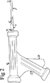
図2を参照するに、図1に示す構成要素が生検銃に組み立てられた図を示す。生検銃は、バレル8、ハンドル11、及び、トリガ10を含む。トリガ10に手動で圧力を加えることにより、切離しブレード9が生検装置の試料採取先端に向かって前進する。
【0032】
図3A及び図3Bは、トリガに圧力をかけることにより切離しブレード9を前進させる機械手段を説明する。ツインブレード1は、バレル8の遠位端(即ち、試料採取先端に最も近い端)に固定され、切離しブレード9はトラック15に沿って自由に摺動可能である。切離しブレードの近位端(即ち、ハンドルに最も近い端)は、押し棒14に固定される。押し棒14の遠位端16は、押し棒14を切離しブレード9に固定するスタッドを有する。押し棒14もトラック15内に入れられ、押し棒14の近位端は、固定ビボット軸19について回転するレバー13に取付けられる。トリガに圧力を加えることにより、レバーがピボット軸19について回転し、それにより、押し棒14及び切離しブレード9が前進する。一端がレバー13の点21に接続され、他端がバレルの近位端の点20に接続されるバネ12が固定される。バネ12は、トリガ10に圧力が加えられると伸張し、トリガ10への圧力が解除されたときには、トリガ12と、押し棒14と、切離しブレード9がもとの位置に戻ることを確実にする。
【0033】
図4A乃至図4Dは、本発明の装置の別の可能な実施例を示す。この実施例は、前の実施例と同じようにハンドル6に固定されるツインブレードを有するが、切離しブレード9は、押し棒14とボタン7に取付けられ、ハンドルの内部トラック15に摺動可能に取付けられる。従って、ボタン7を内部トラック15に沿って前後に摺動させることにより、ツインブレード1に対し押し棒14と切離しブレード9を前後に動かすことができる。
【0034】
図6を参照して説明する実施例における可動式ブレードも、上述した機構と同様の機構を使用しうる。
【0035】
図5A乃至図5Dは、本発明の装置(本発明の装置のハンドルは図5A乃至図5Dには図示せず)を使用して軟組織試料を採取する手順を概略的に示す。軟組織は、皮膚22及び皮下組織23として表し、図面では皮下組織を採取することを目的とする。
【0036】
図5Aにおいて、生検銃(図示せず)は引込まれた位置に設定される。即ち、トリガ10には圧力が加えられておらず、ツインブレードは露出しており、切離しブレードは装置の先端からは引き込められている。この位置において、切離しブレード9の弾性があり内側に曲がるよう鋭くされる先端4は、ツインブレード1の側壁によって、先端4の定位置から離されている。局部麻酔が施され、皮膚が切開され、目的の軟組織に到達することができるようにされる。
【0037】
施術者は、片方の手の指で目的の軟組織を固定し、もう片手の手の指で、目的の軟組織に当てられている露出しているツインブレード1を有する生検銃を保持する。1回の優しい差込動作で、本発明の装置は、要求される深さ(図5A参照)まで入れられる。この時、生検組織の上面及び底面は切断されており、ツインブレードの間に挟まれる試料組織は、その試料組織の側面と遠位端が周りの組織からまだ切り離されていないことにより定位置に保持される。
【0038】
トリガに圧力が加えられて切離しブレード9が前進し、それにより、試料組織の側壁及び遠位端が切断される(図5B参照)。切離しブレード9の内側に曲がる弾性のある鋭くされた先端4が、前進するに従って、ツインブレード先端2の遠位端に回り込んで曲がる。
【0039】
図5Cは、生検装置全体を引抜くことにより無傷の試料が採取される様子を示す。試料24は切離しブレード9が前に出された位置にあることによって保護される。
【0040】
図5Dは、切離しブレード9がもとの位置に戻され、試料を、例えば、ツインブレード1を優しく斜めに離すことにより取り出す様子を示す。
【0041】
図6を参照するに、ツインブレードを有する設計を示す。ここでは、下ブレード26が最初に関心の組織内に入れられ、次に、第2の、即ち、上ブレード25が下のブレード26の先端に合うように入れられる。下ブレードはその先端近くに、内側に向けられた刺又は縁部といった鋭くされた隆起部を有し、これは、2つのブレードが完全に挿入されたときに、装置の遠位端における試料の切断及び保持を支援する。上ブレード25はその先端近く及び側縁に鋭くされた隆起部を有し、これは、上ブレードが前進されるに従って生検試料の側壁を切断する。
【0042】
図7は、1つの1次ブレード28が3面を有し、その1次ブレード28が前に進められるに従って生検組織試料の上面、下面、及び、1つの側壁を切断するツインブレードを有する設計を示す。2次切離しブレード27は、1次ブレードに沿って前進されることにより、生検試料のもう一方の側面及び遠位端を切断する。
【0043】
上述した生検装置は、現行の生検装置に対し多くの改善点を提供する。即ち、ダブルブレードを有する設計は製造するのが単純且つ経済的であり、また、本発明の装置は、組織病理学者が所望する形状により近い形状の組織試料が得られるので無駄のほとんどない高品質の試料をもたらすことができる。本発明の装置は、生検試料の上面及び下面をツインブレードによって切断し、その後、生検試料の1つの側壁又は両方の側壁及び遠位端を切離しブレードによって切断して段階的に切断するので、効率よく生検試料を捕捉する。本発明の装置を使用することにより、出血する可能性が低くなるので患者の安全性が高く、全身麻酔又は大きい外科手術の必要を回避しうる。本発明を利用しての手術は、失敗する可能性が低くなるので患者の痛みが少なくなる。更に、このより効果的なダブルブレード設計により、より大きい試料を採取することができる。本発明の装置を使用しての採取方法は、施術者の負担も軽くする。なぜなら、1回の挑戦で試料を採取できる可能性が高くなり、また、組織の本体から試料を切り離すのにそれほど労力を必要としなくなるからである。
【0044】
当業者には本発明の装置の多くの有効な変形を思いつくことは明らかであり、本発明は上述される実施例に制限されるものではない。例えば、ブレードの遠位端の形状やハンドル形式は、使用目的に応じて変更してもよい。本発明及び本発明の面は、リンパ節生体検査以外にも、他の軟組織の生体検査、特に、その関心の組織が容易に到達可能である場合は適用することができる。このような状況は、皮膚、乳房、筋肉、肝臓、肺、及び、他の軟組織が生体検査を必要とする場合に、切開外科手術の際に行われる生体検査において特に適用され得る。本発明の装置は更に、生検試料が取られる死体解剖時にも適用される。本発明の方法及び装置は、生体内及び死後適用として動物にも適用することができる。
【図面の簡単な説明】
【図1A】 組織採取器のブレードを上から見た斜視図である。
【図1B】 組織採取器のブレードを下から見た斜視図である。
【図1C】 生検装置の組織採取器のツインブレードを示す斜視図である。
【図1D】 生検装置の組織採取器のツインブレードを示す平面図である。
【図1E】 生検装置の組織採取器のツインブレードを示す底面図である。
【図1F】 生検装置の組織採取器のツインブレードを示す側面図である。
【図1G】 試料切離しブレードを下から見た斜視図である。
【図1H】 1対の1次ブレードと引込まれた位置にある試料切離しブレードを含む組織採取器組立体を示す斜視図である。
【図1I】 1対の1次ブレードと前に出された位置にある試料切離しブレードを含む組織採取器組立体を示す斜視図である。
【図1J】 試料切離しブレードを示す側面図である。
【図1K】 試料切離しブレードを示す平面図である。
【図1L】 試料切離しブレードを示す底面図である。
【図2】 生検銃を示す側面図である。
【図3A】 前に出された位置にある試料切離しブレードを有する図2に示す生検銃の断面図である。
【図3B】 引込まれた位置にある試料切離しブレードを有する図2に示す生検銃の断面図である。
【図4A】 引込まれた位置にある試料切離しブレードを有する生検装置を示す平面図である。
【図4B】 引込まれた位置にある試料切離しブレードを有する生検装置を示す側面図である。
【図4C】 前に出された位置にある試料切離しブレードを有する生検装置を示す平面図である。
【図4D】 前に出された位置にある試料切離しブレードを有する生検装置を示す側面図である。
【図5A】 組織試料を採取する生検装置の使用段階の1つを示す図である。
【図5B】 組織試料を採取する生検装置の使用段階の1つを示す図である。
【図5C】 組織試料を採取する生検装置の使用段階の1つを示す図である。
【図5D】 組織試料を採取する生検装置の使用段階の1つを示す図である。
【図6A】 生検装置の上ブレード及び下ブレードを前から見た斜視図である。
【図6B】 生検装置の上ブレード及び下ブレードを後ろから見た斜視図である。
【図6C】 上ブレードの底面図と平面図である。
【図6D】 下ブレードの底面図と平面図である。
【図7A】 生検装置の1次ブレードを前から見た斜視図である。
【図7B】 生検装置の1次ブレードを後ろから見た斜視図である。
【図7C】 生検装置の切離しブレードを前から見た斜視図である。
【図7D】 1次ブレードと切離しブレードを前から見た斜視図である。
【図7E】 1次ブレードの平面図である。
【図7F】 1次ブレードの底面図である。
【図7G】 1次ブレードを示す側面図である。[0001]
The present invention generally relates to an apparatus and method for collecting biopsy samples from human and animal tissues. More particularly, the present invention relates to improvements in the collection of soft tissue such as lymph node tissue.
[0002]
In medical and surgical practice, soft tissue biopsy is a common and important examination. Biopsy samples are typically obtained using a biopsy device based on a hollow round needle or cannula design. As a result, a section of cylindrical tissue is collected. This biopsy device can penetrate deep into the tissue, but often the sample taken is thin or small, which makes it difficult to make an accurate diagnosis. Furthermore, there is essentially no reason why the biopsy sample must be cylindrical. This is because the histopathologist cuts the sample into very thin sections or slices, typically having a thickness of 0.004 millimeters, and then cuts the cut sections or slices for subsequent staining and microscopy. This is because the sample is processed on a glass slide. Therefore, the cylindrical sample is wasteful because only a very small part of the tissue is examined. Furthermore, wounds created by cylindrical devices are prone to bleeding because the sides of the wounds are less likely to stick together.
[0003]
Similar problems occur in the specialized field of lymph node biopsy. Lymph nodes expand in the superficial area due to infection or infiltration by a tumor, and generally a lymph node examination is required to make a diagnosis. Although cells can be collected for cytological examination by inhaling lymph nodes with a needle, this technique is generally useful for distinguishing between benign and malignant conditions, A complete diagnosis cannot be made to determine where a malignant tumor appears to be. Although it is possible to obtain a diagnosis of enlarged lymph nodes in a part of a patient using a conventional cylindrical biopsy needle, the resulting sample is thin and difficult for a histopathologist to make a complete diagnosis It becomes. In particular, there may be cases where scattered abnormalities are missed, and the structure of lymph nodes may not be easily confirmed. Many histopathologists recommend an open lymphadenectomy that can remove complete lymph nodes (those that reach a diameter of 1 to 5 centimeters). This lymphadenectomy exposes the patient to more surgical procedures than necessary (typically compared to examining very thin slices of the lymph nodes), and surgery generally It is performed with general anesthesia rather than local anesthesia. General anesthesia can be avoided because it significantly increases inconvenience for the patient and doctor and also increases the risk to the patient, thereby delaying diagnosis and increasing the cost of the procedure. desirable.
[0004]
A biopsy device that attempts to address some of these problems is known from US 3,800,783 Jamshidi. In this document, a muscle having a generally rectangular blade having a tapered cutting distal end and a hook having a sample fixing stab to be covered and having a slot directed rearward provided in the blade. The inspection device is described. After the sample is captured in the slot, a sheath is placed over the blade to protect the sample when the biopsy device is withdrawn. However, this device has several problems in implementation. For example, the tip of the hook must be inserted deeper than the tissue to be taken to engage the sample tissue at the correct point, and the hook-type design is comparable to the biopsy sample taken It is a small point.
[0005]
Another attempt to address this problem is described in US Pat. No. 4,926,877 Bookwalter, which is mostly similar to the prior art but with a flattened cannula and an end of a biopsy sample. Disclosed is a device having an extensible and resilient blade for detaching the device from surrounding tissue. However, this device still has similar drawbacks associated with conventional designs as described above.
[0006]
FR2,493,137 describes a biopsy device provided with a parallel blade to obtain a skin sample. However, in this device, the blades go to a depth of 1 to 3 millimeters and are separated by up to 5 micrometers, and the blades are bent towards each other to cut the tissue sample. Therefore, the usefulness of this device is very limited.
[0007]
Various other types of biopsy devices are described in US Pat. No. 4,971,067, US Pat. No. 4,168,698, EP0919192A, EP0235489A, US4832045, WO93 / 19675, and GB1,084,640.
[0008]
Thus, it is possible to take a sample with a size larger than the current one, and also to obtain a biopsy sample which is a flatter and therefore more efficient section than that available with known devices. A biopsy device is required.
[0009]
In the present invention, a biopsy device including a tissue collector is provided. The tissue harvester includes a pair of blades that are arranged face to face, substantially parallel to each other, and substantially flat, and a cutting means for separating the tissue sample from the tissue after the biopsy device is inserted. A pair of blades defines two sides of the space that receives the tissue to be harvested. The pair of blades has a leading edge at the tip of the biopsy device that cuts the sample to be collected as the device is inserted into the tissue.
[0010]
According to a second aspect of the present invention, a biopsy device is provided that includes a substantially parallel twin blade and a cutting blade configured to slidably advance along the substantially parallel twin blade. When the generally parallel twin blades are placed in the tissue, a thin flat section of the tissue biopsy sample is cut between the approximately parallel twin blades. The cutting blade is slidably advanced along the substantially parallel twin blades to cut at least the distal end of the tissue biopsy sample.
[0011]
According to another aspect of the present invention, a tissue harvester is provided that includes a pair of blades that are positioned face to face, substantially parallel to each other, and substantially flat. A pair of blades defines two sides of the space that receives the tissue to be harvested. The pair of blades has a leading edge at the tip of the biopsy device that cuts the sample to be collected as the biopsy device is inserted into the tissue. The pair of blades includes a first blade and a second blade that are movable relative to each other.
[0012]
According to a further aspect of the invention, a biopsy device is provided that includes substantially parallel twin blades. When the generally parallel twin blades are advanced through the tissue surface, they cut a thin flat portion of the tissue biopsy sample between the generally parallel twin blades. The biopsy device is configured so that each blade of the twin blade is advanced separately.
[0013]
The present invention further provides a method for obtaining a biopsy sample. The method of the present invention comprises the steps of i) inserting a biopsy device into the tissue to be collected and cutting the top and bottom surfaces of the biopsy sample, and ii) using the biopsy device to Cutting the side end face of the test sample.
[0014]
The present invention further provides a combination of the biopsy device of the present invention and instructions on a carrier medium. The instructions describe how to take a biopsy sample. A method for collecting a biopsy sample includes inserting a biopsy device into a tissue to be collected, cutting the upper end surface and the lower end surface of the biopsy sample, and using the biopsy device. Cutting at least one side edge of the sample.
[0015]
As the biopsy device is inserted, a relatively large and flat tissue sample from surrounding tissue by using a pair of blades arranged face to face with a leading edge that cuts the tissue to be harvested Can be provided. Thus, the biopsy device of the present invention provides a section of tissue having sufficient dimensions to perform a complete and efficient histological examination, while minimizing patient injury and post-treatment. The possibility of bleeding can be reduced. The tissue extractor blades are preferably distinct from each other or distinguished from each other. The two blades define a large space for receiving tissue and are configured to have little effect on the surrounding tissue, making it possible to easily obtain a sample having an optimal size. The present invention further allows the construction of a biopsy device that is simple and inexpensive to manufacture and that can operate easily.
[0016]
The biopsy device of the present invention is based on the recognition that when inserted into soft tissue, two sharpened blades can cut a slice or section of a tissue sample between the two blades without damaging the sample. ing. The biopsy device of the present invention may be used to collect soft tissue, such as live or dead human or animal skin, liver, kidney, or tumor tissue, for pathological studies. In particular, the device of the present invention does not require the patient to undergo intensive or unusual surgical procedures and does not require large openings in the human body, for example obtaining samples from superficial areas such as enlarged lymph nodes. Suitable for
[0017]
The collection of relatively large and flat biopsy samples has a number of advantages over the generally cylindrical tissue samples of the related art. Since the shape of the biopsy sample matches the shape desired by the histopathologist responsible for examining the sample, a larger portion of the sample can be analyzed. That is, the possibility of detecting structural or scattered anomalies is increased. This is because larger continuous surface areas are inspected to help make a correct diagnosis. Also, the two surfaces of the wound made by the tissue extractor blade are easily stuck together by applying pressure from the outside, thus reducing the possibility of bleeding. It is particularly advantageous if a large test sample needs to be obtained, especially if the tissue of interest is superficial or can be easily reached (eg during open therapy or post-mortem examination).
[0018]
A typical biopsy device for soft tissue has a cannula having an inner diameter of about 1 millimeter. Devices with large diameters may provide samples up to 2.5 millimeters. The length of the sample is generally 1 to 2 centimeters. Compared to these, embodiments of the present invention can easily provide a sample having a width of 3 to 15 millimeters, a thickness of 1 to 2 millimeters, and a length of 1 to 3 centimeters. Although the preferred embodiment of the present invention provides a sample having a width of about 4 millimeters and a thickness of 1 millimeter, these values can be easily adjusted to the requirements of a particular application. For example, a small sample having a length of 1 centimeter or less and / or a thickness of 1 millimeter or less (minimum of about 0.5 millimeters) may not need such a small sample in practice, Can be provided.
[0019]
The space for receiving tissue is preferably open along one or both sides. Thus, the blades are provided with edges that extend substantially perpendicular to the plane of the blades and face each other. Thereby, one or two longitudinal openings are defined in the space for receiving tissue. This is advantageous because it allows a much thinner section to be cut in conventional cannula type devices than if the sidewalls surround the biopsy sample. When the biopsy device is first inserted, the collected tissue is kept connected to the surrounding tissue at the opening, thereby supporting the collected tissue and providing a better quality sample. The This is particularly useful when the tissue to be collected is fibrous and that the tissue is retained on the side when the biopsy device is inserted. After inserting the device, the side of the sample is separated from the surrounding tissue, as described in detail below, by conventional surgical means or the mechanical structure of the biopsy device.
[0020]
The blades are preferably substantially parallel to each other and flat. This assists in securing large and flat tissue samples within the biopsy device and reduces damage to the tissue to be harvested.
[0021]
In the preferred embodiment, a pair of blades of a biopsy device are inserted simultaneously. It has been found that by manufacturing a pair of blades from stainless steel, it is possible to form a blade with the required sharpness and stiffness needed to be simply manually pushed into the tissue to be harvested. Yes. However, for tissues that are particularly difficult to cut, the blades can also be configured to be movable so that they can be inserted sequentially relative to each other, so that a pair of blades vibrate relative to each other. (Or both blades may be made to oscillate in tandem). In one such biopsy device variant, the blades pivot relative to each other to perform a small scissor-like opening and closing action. The blade is preferably driven at a high frequency by a motor or vibrator. The blade is advantageously driven at an ultrasonic frequency using, for example, an electric oscillator or an ultrasonic transducer.
[0022]
The blade is preferably tapered toward the tip of the biopsy device to facilitate insertion of the biopsy device into the tissue to be collected. This thinning facilitates cutting the end of the tissue sample from the surrounding tissue as will be described below. In the preferred embodiment, the blade is thinned to a point.
[0023]
The biopsy device further advantageously includes a cutting means for cutting the biopsy sample from the tissue after the biopsy device is inserted. This allows the sample to be cut in stages from the surrounding tissue. That is, the top and bottom surfaces of the sample are first cut and then the remaining points connected to the surrounding tissue are cut. This makes it easier to maintain the form of the biopsy sample, thus providing a larger usable sample. This further saves money and time by reducing the patient's discomfort by making it easier to obtain useful samples each time a biopsy device is inserted.
[0024]
The cutting means is preferably cut along the side of the space that receives the tissue. In one embodiment, the cutting means cuts substantially perpendicular to the face of the blade. The cutting means preferably cuts the end of the sample from the tissue adjacent to the tip of the device. In a preferred configuration, this is accomplished by slidably mounting a sample detachment blade on the biopsy device and cutting either side of the blade located opposite the tissue collector. To cut the end of the sample, it is preferred that a portion of the detachment blade is resilient and bends inwardly around the tip of the biopsy device as the detachment blade is advanced. This can be accomplished by providing a carriage that can be mounted on either side of a blade guide having a sprung cutting extension that is biased to bend toward the tip of two opposingly disposed blades. In this embodiment, the required elastic biasing of the cutting part of the separating blade can be achieved by forming the cutting extension from a sprung nickel titanium alloy. With such a configuration, the sprung extension of the sample separation blade bends around the tip of the biopsy after the side and end of the sample are cut, and protects the sample when the biopsy device is pulled out. And help fix.
[0025]
In another embodiment, a separate sample detachment blade is advanced along either side of the two opposed primary blades. Additionally or alternatively, a cutting blade can be inserted on the upper surface of the primary blade to cut the tip of the sample. The cutting blade may be provided with a cutting extension on each side to cut along the side of the primary blade.
[0026]
The detachment blade is preferably connected to the actuation means and is controllable to cut the sample from the tissue. In one embodiment, the actuating means is connected to a button on the biopsy device that operates along a guide slot so that the sample detachment blade is advanced after the biopsy device is inserted. The actuating means may be biased so as to be resilient to move the carriage away from the tip of the biopsy device. The biopsy device is preferably suitable for operation with one hand, and may include, for example, a pistol grip and trigger for operating the sample detachment blade.
[0027]
In a particularly preferred embodiment, the lymph node biopsy device has twin blades placed face to face in parallel planes. Twin blades have a sharpened tip to assist penetration into the tissue. The lymph node biopsy device further includes a cutting blade having a distal tip that is bent inward, resilient, and sharpened. The separating blade can be slidably moved along the twin blade by the track, so that in the position where the separating blade is retracted, only the twin blade is exposed to the sample to be collected, A twin blade can be applied to the tissue to cut the top and bottom surfaces of the biopsy sample. By advancing the cutting blade, the side wall and the distal end of the biopsy sample can be cut. The twin blades and detachment blades can be a) fixed to a handle having dimensions that fits conveniently in the surgeon's hand. More specifically, the twin blade is attached to the handle, the release blade is attached to the button, and the release blade is moved back and forth along the twin blade by moving the button back and forth along the track. Alternatively, the twin blade and the cutting blade can be fixed to a gun-like device having b) a handle, a trigger, a push rod, and a barrel. Twin blades are attached to the end of the barrel. In this configuration, the cutting blade is preferably in the barrel when in the retracted position. As the push bar is advanced along the track in the barrel (achieved by applying pressure to the trigger), the release blade is advanced out of the barrel along the sides of the twin blades. Thus, when the biopsy sample is fixed by being gently compressed and pinched between the twin blades, the tip of the detachment blade cuts the side wall and the distal end of the biopsy sample. In the fully advanced position, the tip of the cutting blade overlaps the distal end of the twin blade. Inside the gun body, by applying pressure to the trigger, the cutting blade is advanced, the spring is stretched, and by releasing the pressure on the trigger, the spring is restored and the cutting blade is retracted A lever, pivot, spring, or other similar arrangement is provided that provides a mechanical or electromechanical means.
[0028]
The above and other aspects of the present invention will now be described by way of example with reference to the accompanying drawings.
[0029]
Referring initially to FIGS. 1A-1F, these drawings show a pair of primary blades 1 positioned opposite to a tissue harvester. The primary blade defines the top and bottom surfaces of the volume or space that receives the sample. The end of each primary blade has a sharpened
[0030]
1G to 1L show a version of the sample separating blade 9. As shown in FIGS. 1H and 1I, the separating blade 9 is fitted on the pair of primary blades 1, and a side cutting blade or blade guide portion 5 sandwiched around the back surface of the primary blade by the tab 3. Mounted. Each blade guide 5 has an elastic cutting extension 4. The extension 4 contacts the side edge of the primary blade. The extension 4 is configured to be biased inward toward the sample receiving volume between the primary blades 1. This is realized, for example, by configuring the extension 4 to bend inward naturally. In this way, in the state where the sample separating blade is retracted as shown in FIG. 1H, the leading edge of the extension 4 comes into contact with the side edges of the pair of primary blades, and as the separating blade is put forward, Cut along the side edges. When the end of the extension 4 reaches a tapered portion that is tapered toward the inside of the tip of the biopsy device, the end of the extension is bent inward, so that when the separating blade is advanced further, Bend inward to follow the contour of the tip of the inspection device. Thus, the end of the extension 4 functions to cut the end of the biopsy sample from the surrounding tissue as shown in FIG. 1I.
[0031]
Referring to FIG. 2, a view of the components shown in FIG. 1 assembled into a biopsy gun is shown. The biopsy gun includes a barrel 8, a
[0032]
3A and 3B illustrate mechanical means for advancing the detaching blade 9 by applying pressure to the trigger. The twin blade 1 is fixed to the distal end of the barrel 8 (that is, the end closest to the sampling tip), and the separating blade 9 is freely slidable along the track 15. The proximal end of the detachment blade (ie, the end closest to the handle) is secured to the
[0033]
4A-4D show another possible embodiment of the device of the present invention. This embodiment has twin blades fixed to the handle 6 as in the previous embodiment, but the detaching blade 9 is attached to the
[0034]
The movable blade in the embodiment described with reference to FIG. 6 can also use the same mechanism as described above.
[0035]
5A-5D schematically illustrate a procedure for collecting a soft tissue sample using the device of the present invention (the handle of the device of the present invention is not shown in FIGS. 5A-5D). The soft tissue is represented as
[0036]
In FIG. 5A, the biopsy gun (not shown) is set to the retracted position. That is, no pressure is applied to the
[0037]
The practitioner secures the target soft tissue with the finger of one hand and holds the biopsy gun with the exposed twin blade 1 applied to the target soft tissue with the finger of the other hand. With one gentle plug-in operation, the device of the present invention is inserted to the required depth (see FIG. 5A). At this time, the top and bottom surfaces of the biopsy tissue are cut, and the sample tissue sandwiched between the twin blades is positioned in place because the side and distal ends of the sample tissue are not yet separated from the surrounding tissue. Retained.
[0038]
Pressure is applied to the trigger and the cutting blade 9 is advanced, thereby cutting the side wall and distal end of the sample tissue (see FIG. 5B). As the elastic sharpened tip 4 that bends inside the detaching blade 9 advances, it wraps around the distal end of the
[0039]
FIG. 5C shows how an intact sample is taken by pulling out the entire biopsy device. The sample 24 is protected by the detaching blade 9 being in the previously extended position.
[0040]
FIG. 5D shows how the cutting blade 9 is returned to its original position and the sample is removed, for example, by gently releasing the twin blade 1 diagonally.
[0041]
Referring to FIG. 6, a design with twin blades is shown. Here, the lower blade 26 is first placed in the tissue of interest, and then the second or upper blade 25 is placed to fit the tip of the lower blade 26. The lower blade has a sharpened ridge near its tip, such as an inwardly directed stab or edge, which allows the sample at the distal end of the device to be fully inserted when the two blades are fully inserted. Support cutting and holding. Upper blade 25 has a ridge sharpened near its tip and on the side edges, which cuts the side wall of the biopsy sample as the upper blade is advanced.
[0042]
FIG. 7 shows a design with one
[0043]
The biopsy device described above provides many improvements over current biopsy devices. That is, the design with double blades is simple and economical to manufacture, and the device of the present invention provides a tissue sample with a shape closer to the shape desired by the histopathologist, so that there is little waste and high quality. Samples can be produced. The device of the present invention cuts the upper and lower surfaces of the biopsy sample with twin blades, and then cuts one or both of the side walls and the distal end of the biopsy sample and cuts with the blade in stages. Capture biopsy samples efficiently. By using the device of the present invention, the patient's safety is increased because the possibility of bleeding is reduced, and the need for general anesthesia or major surgery can be avoided. Surgery using the present invention reduces the patient's pain because it is less likely to fail. In addition, this more effective double blade design allows larger samples to be taken. The sampling method using the apparatus of the present invention reduces the burden on the operator. This is because it is more likely that a sample can be collected in a single challenge, and less effort is required to separate the sample from the body of the tissue.
[0044]
It will be apparent to those skilled in the art that many effective variations of the apparatus of the present invention can be envisaged and the present invention is not limited to the embodiments described above. For example, the shape of the distal end of the blade and the handle type may be changed according to the purpose of use. In addition to lymph node biopsy, the present invention and aspects of the present invention can be applied to other soft tissue biopsy, especially when the tissue of interest is easily reachable. Such a situation can be especially applied in biopsy performed during open surgery where skin, breast, muscle, liver, lungs, and other soft tissues require biopsy. The device of the present invention is also applied during autopsy when a biopsy sample is taken. The method and apparatus of the present invention can also be applied to animals as in vivo and post-mortem applications.
[Brief description of the drawings]
FIG. 1A is a perspective view of a blade of a tissue collector as viewed from above.
FIG. 1B is a perspective view of the blade of the tissue collector seen from below.
FIG. 1C is a perspective view showing a twin blade of a tissue collector of a biopsy device.
1D is a plan view showing a twin blade of a tissue collector of a biopsy device. FIG.
FIG. 1E is a bottom view showing a twin blade of a tissue collector of a biopsy device.
FIG. 1F is a side view showing a twin blade of a tissue collector of a biopsy device.
FIG. 1G is a perspective view of a sample cutting blade as seen from below.
FIG. 1H is a perspective view showing a tissue extractor assembly including a pair of primary blades and a sample detachment blade in a retracted position.
FIG. 1I is a perspective view of a tissue harvester assembly that includes a pair of primary blades and a sample detachment blade in a previously extended position.
FIG. 1J is a side view showing a sample cutting blade.
FIG. 1K is a plan view showing a sample cutting blade.
FIG. 1L is a bottom view showing a sample cutting blade.
FIG. 2 is a side view showing a biopsy gun.
3A is a cross-sectional view of the biopsy gun shown in FIG. 2 having a sample detachment blade in a previously extended position.
3B is a cross-sectional view of the biopsy gun shown in FIG. 2 having a sample detachment blade in a retracted position.
FIG. 4A is a plan view showing a biopsy device having a sample detaching blade in a retracted position.
FIG. 4B is a side view showing a biopsy device having a sample detachment blade in a retracted position.
FIG. 4C is a plan view showing a biopsy device having a sample detachment blade in a previously extended position.
FIG. 4D is a side view of a biopsy device having a sample detachment blade in a previously extended position.
FIG. 5A is a diagram illustrating one of the stages of use of a biopsy device for collecting tissue samples.
FIG. 5B is a diagram illustrating one of the stages of use of a biopsy device for collecting tissue samples.
FIG. 5C illustrates one of the stages of use of a biopsy device that collects a tissue sample.
FIG. 5D is a diagram illustrating one of the stages of use of a biopsy device that collects a tissue sample.
FIG. 6A is a perspective view of an upper blade and a lower blade of the biopsy device as viewed from the front.
FIG. 6B is a perspective view of the upper blade and the lower blade of the biopsy device as viewed from behind.
FIG. 6C is a bottom view and a plan view of the upper blade.
FIG. 6D is a bottom view and a plan view of the lower blade.
FIG. 7A is a perspective view of the primary blade of the biopsy device as seen from the front.
FIG. 7B is a perspective view of the primary blade of the biopsy device as seen from behind.
FIG. 7C is a perspective view of the cutting blade of the biopsy device as seen from the front.
FIG. 7D is a perspective view of the primary blade and the separating blade as seen from the front.
FIG. 7E is a plan view of the primary blade.
FIG. 7F is a bottom view of the primary blade.
FIG. 7G is a side view showing the primary blade.
Claims (37)
該組織採取器は、採取されるべき組織への該組織採取器の挿入の方向によって画定される長手方向軸を有する一般的に長手方向の形状を有し、
該組織採取器は、互いに対して平行に向かい合わせに配置され且つ平らである、1対のブレードを有し、
該1対のブレードは、前記長手方向軸に沿って互いに対して可動である第1及び第2のブレードを有し、採取されるべき組織を受容する組織受容空間の2つの側面を画定し、当該生検装置の先端において当該生検装置が組織へと挿入される際に採取される組織を切断する前縁部を有し、
前記組織採取器は、当該生検装置が挿入された後に組織から試料を切断する切断手段を更に有する、
生検装置。A biopsy device having a tissue collector,
The tissue harvester has a generally longitudinal shape having a longitudinal axis defined by the direction of insertion of the tissue harvester into the tissue to be harvested;
The tissue harvester has a pair of blades that are positioned parallel and opposite to each other and are flat,
The pair of blades have first and second blades that are movable relative to each other along the longitudinal axis and define two sides of a tissue receiving space that receives tissue to be harvested; Having a leading edge that cuts the tissue collected when the biopsy device is inserted into the tissue at the tip of the biopsy device;
The tissue collector further has a cutting means for cutting the sample from the tissue after the biopsy device is inserted.
Biopsy device.
請求項1記載の生検装置。The cutting means has a third blade;
The biopsy device according to claim 1.
請求項2記載の生検装置。The third blade is disposed outside a space for receiving the tissue to be harvested;
The biopsy device according to claim 2.
請求項1乃至3のうちいずれか一項記載の生検装置。A space for receiving the tissue to be harvested opens along a third side, the third side having an edge defined by an edge of the blade disposed oppositely;
The biopsy device according to any one of claims 1 to 3.
請求項4記載の生検装置。A space for receiving the tissue to be harvested opens along a fourth side opposite the third side, the fourth side being defined by an edge of the blade disposed oppositely. Having an edge,
The biopsy device according to claim 4.
請求項4又は5記載の生検装置。The cutting means is configured to cut tissue adjacent to at least one side edge of the blade;
The biopsy device according to claim 4 or 5.
請求項1乃至6のうちいずれか一項記載の生検装置。The first blade and the second blade are configured to be sequentially advanced into the harvested tissue;
The biopsy device according to any one of claims 1 to 6.
請求項7記載の生検装置。Drive means for swinging one blade of the pair of blades with respect to the other blade;
The biopsy device according to claim 7.
請求項1乃至8のうちいずれか一項記載の生検装置。And further comprising at least one side cutting blade to cut a side of the harvested tissue adjacent to a side defined by one blade of the pair of opposed blades. The side cutting blade is attached to one blade of the pair of blades arranged facing each other.
The biopsy device according to any one of claims 1 to 8.
請求項1乃至9のうちいずれか一項記載の生検装置。One blade of the pair of blades disposed opposite each other has a stab that is directed inward near the tip of the biopsy device to assist in holding the sample.
The biopsy device according to any one of claims 1 to 9.
請求項1乃至10のうちいずれか一項記載の生検装置。In a plane defined by the blades, the width of at least one of the pair of blades arranged opposite to each other is narrowed toward the tip of the biopsy device;
The biopsy device according to any one of claims 1 to 10.
請求項11記載の生検装置。The cutting means comprises a blade for cutting along at least one open side of a space for receiving the tissue to be harvested;
The biopsy device according to claim 11.
請求項12記載の生検装置。The cutting means is configured to cut across the end of the sample adjacent to the tip of the biopsy device;
The biopsy device according to claim 12.
請求項12又は13記載の生検装置。The cutting means is configured to cut along both sides of the space receiving the tissue to be harvested;
The biopsy device according to claim 12 or 13.
請求項1記載の生検装置。The cutting means is configured to cut the harvested tissue along one or both sides of the space that receives the tissue to be harvested defined by the pair of blades arranged face to face. A movable sample detaching blade slidably attached to the tissue collector.
The biopsy device according to claim 1.
請求項15記載の生検装置。A portion of the movable sample detachment blade is elastic and is inward toward a space that receives the sample to be collected to assist in cutting the end of the tissue sample adjacent to the biopsy device tip. Energized by
The biopsy device according to claim 15.
請求項15又は16記載の生検装置。The movable sample separating blade has a pair of blade portions arranged to face each other.
The biopsy device according to claim 15 or 16.
請求項1記載の生検装置。The space for receiving the tissue to be collected has a third side closed, and a movable blade is provided for cutting along the fourth side of the space for receiving the tissue to be collected.
The biopsy device according to claim 1.
前記可動ブレードは、前記組織試料の前記端にわたって切断することを容易にするよう前記第3の側面に向かって付勢される、
請求項18記載の生検装置。The pair of blades arranged opposite each other is narrowed toward the third side surface,
The movable blade is biased toward the third side to facilitate cutting across the end of the tissue sample;
The biopsy device according to claim 18.
請求項15乃至19のうちいずれか一項記載の生検装置。Further comprising actuating means for moving the movable blade to facilitate separation of the sample;
The biopsy device according to any one of claims 15 to 19.
請求項20記載の生検装置。Configured to be operated with one hand,
21. The biopsy device according to claim 20.
前記作動手段は、トリガにより動作されるバネを有する、
請求項20又は21記載の生検装置。Further comprising a handle attached to the tissue harvester;
The actuating means has a spring operated by a trigger,
The biopsy device according to claim 20 or 21.
該ツインブレードは、長手方向において組織を前進する際に、前記ツインブレードの間において組織生検の薄く平らなセクションを切断及び保持し、前記ブレードの第1のブレードは、前記組織生検の保持を支援するよう前記ブレードにわたる段階を有し、前記ブレードの第2のブレードは、前記組織生検の側面を切断するよう2つの側面切断部を有し、
前記第2のブレードは、前記長手方向において前記第1のブレードに対して可動であり、前記第1のブレードが前記組織生検の前記平らなセクションの第1の面を切断するよう前記組織へと前進した後に、前記第2のブレードは、前記組織生検の前記側面、及び前記第1の面に対向する前記組織の前記平らなセクションの第2の面を切断するよう前進可能であるようにされる、
生検装置。A biopsy device having parallel twin blades,
The twin blades cut and hold a thin, flat section of tissue biopsy between the twin blades as the tissue is advanced in the longitudinal direction, and the first blade of the blade holds the tissue biopsy The second blade of the blade has two side cuts to cut the side of the tissue biopsy; and
The second blade is movable relative to the first blade in the longitudinal direction, and the first blade is adapted to cut the first surface of the flat section of the tissue biopsy into the tissue. The second blade is advanceable to cut the side surface of the tissue biopsy and the second surface of the flat section of the tissue opposite the first surface. ,
Biopsy device.
請求項23記載の装置。The first blade of the blade has a tip and is tapered toward the tip;
24. The apparatus of claim 23.
前記平行なツインブレードは、該ハンドル上に取り付けられ、
更には、前記ブレードの前記第2のブレードを前進させるようトリガを有する、
請求項23乃至24のうちいずれか一項記載の装置。Has a handle,
The parallel twin blades are mounted on the handle;
And a trigger to advance the second blade of the blade;
25. Apparatus according to any one of claims 23 to 24.
請求項25記載の装置。The second blade of the blade is attached with a spring;
26. The apparatus of claim 25.
前記平行なツインブレードは、該ハンドル上に取り付けられ、
前記第2のブレードは、前記ハンドルの内部トラックに摺動可能に取り付けられる、
請求項23乃至24のうちいずれか一項記載の装置。Has a handle,
The parallel twin blades are mounted on the handle;
The second blade is slidably attached to an internal track of the handle;
25. Apparatus according to any one of claims 23 to 24.
請求項27記載の装置。On the track, a push rod and a button are slidably attached, and by moving the button back and forth, the second blade of the blade is moved back and forth.
28. The apparatus of claim 27.
該組織採取器は、採取されるべき組織への該組織採取器の挿入の方向によって画定される長手方向軸を有する一般的に長手方向の形状を有し、
該組織採取器は、互いに対して平行に向かい合わせに配置され且つ平らである、1対のブレードを有し、前記ブレードは、採取されるべき組織を受容する組織受容空間の2つの側面を画定し、当該装置の先端において、当該装置が前記組織へと挿入される際に前記採取される組織を切断する前縁部を有し、前記1対のブレードは、第1のブレード及び第2のブレードを有し、前記第1及び第2のブレードは、前記長手方向軸に沿って互いに対して長手方向に可動であり、前記採取される組織へと順次長手方向に前進されるよう構成される、
生検装置。A biopsy device having a tissue collector,
The tissue harvester has a generally longitudinal shape having a longitudinal axis defined by the direction of insertion of the tissue harvester into the tissue to be harvested;
The tissue harvester has a pair of blades arranged parallel and opposite to each other and flat, said blades defining two sides of a tissue receiving space for receiving the tissue to be harvested. And having a leading edge for cutting the tissue to be collected when the device is inserted into the tissue at the tip of the device, wherein the pair of blades includes a first blade and a second blade Having a blade, wherein the first and second blades are longitudinally movable relative to each other along the longitudinal axis and configured to be sequentially advanced longitudinally into the harvested tissue ,
Biopsy device.
請求項29記載の生検装置。A space for receiving the tissue to be harvested opens along a third side, the third side having an edge defined by an edge of the blade disposed oppositely;
30. A biopsy device according to claim 29.
請求項30記載の生検装置。A space for receiving the tissue to be harvested opens along a fourth side substantially opposite the third side, the fourth side being an edge of the blade disposed oppositely Having an edge defined by
The biopsy device according to claim 30.
請求項29乃至31のうちいずれか一項記載の生検装置。The at least one side cutting blade further comprising at least one side cutting blade that cuts one side of the sample tissue adjacent to a side defined by one of the pair of blades disposed opposite to each other. Is attached to one blade of the pair of blades arranged face to face,
32. A biopsy device according to any one of claims 29 to 31.
請求項29乃至32のうちいずれか一項記載の生検装置。One of the pair of blades arranged face-to-face has a stab or inward projection near the tip of the biopsy device that is directed inward to assist in holding the sample tissue.
The biopsy device according to any one of claims 29 to 32.
請求項32又は33記載の生検装置。It further has drive means for swinging one blade with respect to the other blade,
The biopsy device according to claim 32 or 33.
請求項29乃至31のうちいずれか一項記載の生検装置。Further comprising a cutting means for cutting the sample from the tissue after the biopsy device is inserted;
32. A biopsy device according to any one of claims 29 to 31.
請求項35記載の生検装置。The cutting means is configured to cut along at least one open side of the space receiving the tissue to be harvested;
36. A biopsy device according to claim 35.
該実質的に平行なツインブレードは、組織の平面を通って前進される際に、前記実質的に平行なツインブレード間で組織生検の薄く平らなセクションを切断し、当該生検装置は、前記ツインブレードの各ブレードが別々に前進するよう構成される、
生検装置。A biopsy device having substantially parallel twin blades,
When the substantially parallel twin blades are advanced through the tissue plane, they cut a thin flat section of tissue biopsy between the substantially parallel twin blades, the biopsy device comprising: Each blade of the twin blade is configured to advance separately,
Biopsy device.
Applications Claiming Priority (3)
| Application Number | Priority Date | Filing Date | Title |
|---|---|---|---|
| GB0009927.5 | 2000-04-20 | ||
| GBGB0009927.5A GB0009927D0 (en) | 2000-04-20 | 2000-04-20 | Biopsy device |
| PCT/GB2001/001674 WO2001080743A1 (en) | 2000-04-20 | 2001-04-12 | Biopsy device |
Publications (3)
| Publication Number | Publication Date |
|---|---|
| JP2003530942A JP2003530942A (en) | 2003-10-21 |
| JP2003530942A5 JP2003530942A5 (en) | 2008-06-05 |
| JP4628637B2 true JP4628637B2 (en) | 2011-02-09 |
Family
ID=9890388
Family Applications (1)
| Application Number | Title | Priority Date | Filing Date |
|---|---|---|---|
| JP2001577847A Expired - Fee Related JP4628637B2 (en) | 2000-04-20 | 2001-04-12 | Biopsy equipment |
Country Status (8)
| Country | Link |
|---|---|
| US (1) | US7722548B2 (en) |
| EP (1) | EP1276420B1 (en) |
| JP (1) | JP4628637B2 (en) |
| AT (1) | ATE406841T1 (en) |
| AU (1) | AU4854901A (en) |
| DE (1) | DE60135644D1 (en) |
| GB (1) | GB0009927D0 (en) |
| WO (1) | WO2001080743A1 (en) |
Families Citing this family (13)
| Publication number | Priority date | Publication date | Assignee | Title |
|---|---|---|---|---|
| US9414855B1 (en) * | 2007-11-05 | 2016-08-16 | Cardica, Inc. | Anvil knife for anastomosis tool |
| GB2469082A (en) * | 2009-03-31 | 2010-10-06 | Nhs Innovations South East | Surgical Instrument for Biopsy |
| US8535240B2 (en) * | 2010-03-30 | 2013-09-17 | Siteselect Medical Technologies, Inc. | Tissue excision device with a retracting stylet blade |
| EP2598037B1 (en) * | 2010-07-30 | 2016-11-02 | Cook Medical Technologies LLC | Coaxial incisional full-core biopsy needle |
| KR101471465B1 (en) * | 2012-11-27 | 2014-12-10 | (주)티엔티리써치 | Biopsy Apparatus for Large Animals |
| US9427378B2 (en) | 2013-04-30 | 2016-08-30 | Avent, Inc. | Gastric jejunal tube with an enlarged jejunal lumen |
| US20150088137A1 (en) * | 2013-09-26 | 2015-03-26 | Misonix Incorporated | Ultrasonic surgical instrument with dual end effector |
| US10028762B1 (en) * | 2013-10-14 | 2018-07-24 | Percutaneous Cosmetic Devices LLC | Method of cutting soft tissue under facial skin |
| WO2015191749A1 (en) * | 2014-06-10 | 2015-12-17 | Indiana University Research & Technology Corporation | System and method for extracting tissue samples |
| US10376248B2 (en) | 2016-07-15 | 2019-08-13 | Tissuegrab Biopsy Systems Llc | Mammal and fish biopsy dart |
| UY4636S (en) * | 2017-09-08 | 2018-10-31 | Snpshot Trustee Ltd | SAMPLING DEVICE |
| USD869677S1 (en) * | 2017-09-08 | 2019-12-10 | Snpshot Trustee Limited | Sampler device |
| USD885572S1 (en) * | 2018-03-12 | 2020-05-26 | Olympus Corporation | Biopsy needle |
Family Cites Families (21)
| Publication number | Priority date | Publication date | Assignee | Title |
|---|---|---|---|---|
| GB1084640A (en) | 1966-04-04 | 1967-09-27 | John James Demarco | Surgical instrument |
| US3683892A (en) * | 1970-07-13 | 1972-08-15 | Battelle Development Corp | Device for the extraction of core samples |
| US3800783A (en) | 1972-06-22 | 1974-04-02 | K Jamshidi | Muscle biopsy device |
| US3998229A (en) * | 1974-11-15 | 1976-12-21 | Barton Richard T | Surgical margin blade |
| US4168698A (en) | 1977-06-16 | 1979-09-25 | Professional Staff Association Of The Los Angeles County Harbor General Hospital | Endocervical strip biopsy instrument |
| FR2493137A1 (en) * | 1980-11-05 | 1982-05-07 | Mahuzier Francois | Biopsy instrument for obtaining skin sample - comprises pair of parallel blades sliding in fixed frame and mounted on spring-loaded plunger |
| US4667684A (en) | 1985-02-08 | 1987-05-26 | Bio-Medical Resources, Inc. | Biopsy device |
| US4651752A (en) * | 1985-03-08 | 1987-03-24 | Fuerst Erwin J | Biopsy needle |
| US4832045A (en) | 1988-03-18 | 1989-05-23 | Goldberger Robert E | Biopsy instrument |
| US4971067A (en) | 1988-05-05 | 1990-11-20 | Lee Bolduc | Biopsy instrument with a disposable cutting blade |
| US4926877A (en) | 1989-04-24 | 1990-05-22 | Bookwalter John R | Biopsy needle with completely closable cutting end bore |
| US5462062A (en) * | 1991-12-13 | 1995-10-31 | Rubinstein; Daniel B. | Bone marrow biopsy needle with cutting and/or retaining device at distal end |
| US5471992A (en) * | 1994-02-08 | 1995-12-05 | Boston Scientific Corporation | Multi-motion cutter multiple biopsy sampling device |
| US5570700A (en) * | 1994-10-03 | 1996-11-05 | Vogeler; Douglas M. | Elliptical biopsy punch |
| AU7112696A (en) * | 1995-09-18 | 1997-04-09 | Exatech, Inc. | Counter-balanced oscillating surgical saw |
| US5922000A (en) * | 1997-11-19 | 1999-07-13 | Redfield Corp. | Linear punch |
| AU9326698A (en) | 1997-11-24 | 1999-06-10 | Johnson & Johnson Research Pty. Limited | Biopsy instrument including tip for tissue dilation |
| US6517498B1 (en) * | 1998-03-03 | 2003-02-11 | Senorx, Inc. | Apparatus and method for tissue capture |
| US6264668B1 (en) * | 1998-09-16 | 2001-07-24 | Arnold S. Prywes | Ophthalmologic instrument for producing a fistula in the sclera |
| JP3596340B2 (en) * | 1999-03-18 | 2004-12-02 | 株式会社日立製作所 | Surgical insertion device |
| FR2791433A1 (en) | 1999-03-24 | 2000-09-29 | Oreal | Instrument for capturing and collecting dead skin cells, comprises two blades with negative edges fixed side by side within a moulded handle and pumped collection tool with reduced section tube |
-
2000
- 2000-04-20 GB GBGB0009927.5A patent/GB0009927D0/en not_active Ceased
-
2001
- 2001-04-12 AU AU48549/01A patent/AU4854901A/en not_active Abandoned
- 2001-04-12 WO PCT/GB2001/001674 patent/WO2001080743A1/en active IP Right Grant
- 2001-04-12 AT AT01921575T patent/ATE406841T1/en not_active IP Right Cessation
- 2001-04-12 EP EP01921575A patent/EP1276420B1/en not_active Expired - Lifetime
- 2001-04-12 DE DE60135644T patent/DE60135644D1/en not_active Expired - Lifetime
- 2001-04-12 JP JP2001577847A patent/JP4628637B2/en not_active Expired - Fee Related
- 2001-04-12 US US10/258,323 patent/US7722548B2/en not_active Expired - Fee Related
Also Published As
| Publication number | Publication date |
|---|---|
| GB0009927D0 (en) | 2000-06-07 |
| ATE406841T1 (en) | 2008-09-15 |
| WO2001080743A1 (en) | 2001-11-01 |
| US20030171766A1 (en) | 2003-09-11 |
| US7722548B2 (en) | 2010-05-25 |
| EP1276420A1 (en) | 2003-01-22 |
| EP1276420B1 (en) | 2008-09-03 |
| AU4854901A (en) | 2001-11-07 |
| DE60135644D1 (en) | 2008-10-16 |
| JP2003530942A (en) | 2003-10-21 |
Similar Documents
| Publication | Publication Date | Title |
|---|---|---|
| US5127419A (en) | Biopsy instrument with slotted driving member | |
| JP3647863B2 (en) | Multiple biopsy specimen extraction device | |
| USRE38776E1 (en) | Surgical biopsy instrument | |
| EP2303153B1 (en) | Biopsy device | |
| US7491177B2 (en) | Biopsy needle and method | |
| US8936557B2 (en) | Punch biopsy device | |
| JP5686448B2 (en) | Hair follicle unit removal device having a rotation holding member | |
| JP4628637B2 (en) | Biopsy equipment | |
| US20150335319A1 (en) | Flexible biopsy collection device and related methods of use | |
| US7278971B2 (en) | Endoscopic multiple biopsy forceps with swing member | |
| US20040215187A1 (en) | Apparatus and method for accessing a body site | |
| JP2004507291A (en) | Percutaneous biopsy instrument | |
| JP2005520617A (en) | Biopsy needle | |
| US20080045858A1 (en) | Device for Transcutaneous Biopsy of Tissues | |
| JPH09503404A (en) | Multiple biopsy sample collection device | |
| US20060084885A1 (en) | Endoscopic multiple biopsy forceps with swing member | |
| CN107205733B (en) | Distal tip tissue sampling arrangement | |
| JP4175675B2 (en) | Continuous biopsy tool | |
| JP5775866B2 (en) | Medical instruments | |
| US11172912B2 (en) | Biopsy needle and medical device incorporating the same | |
| JP2001070307A (en) | Tissue collecting apparatus | |
| JPH03139340A (en) | Treating implement for endoscope | |
| US20160095584A1 (en) | Endoscopic needle with rotary jaw for lateral acquisition | |
| JP4373536B2 (en) | Endoscopic biopsy forceps with needle | |
| KR102595500B1 (en) | Endoscopic forcep |
Legal Events
| Date | Code | Title | Description |
|---|---|---|---|
| A521 | Request for written amendment filed |
Free format text: JAPANESE INTERMEDIATE CODE: A523 Effective date: 20080410 |
|
| A621 | Written request for application examination |
Free format text: JAPANESE INTERMEDIATE CODE: A621 Effective date: 20080410 |
|
| TRDD | Decision of grant or rejection written | ||
| A01 | Written decision to grant a patent or to grant a registration (utility model) |
Free format text: JAPANESE INTERMEDIATE CODE: A01 Effective date: 20101012 |
|
| A01 | Written decision to grant a patent or to grant a registration (utility model) |
Free format text: JAPANESE INTERMEDIATE CODE: A01 |
|
| A61 | First payment of annual fees (during grant procedure) |
Free format text: JAPANESE INTERMEDIATE CODE: A61 Effective date: 20101110 |
|
| FPAY | Renewal fee payment (event date is renewal date of database) |
Free format text: PAYMENT UNTIL: 20131119 Year of fee payment: 3 |
|
| R150 | Certificate of patent or registration of utility model |
Ref document number: 4628637 Country of ref document: JP Free format text: JAPANESE INTERMEDIATE CODE: R150 Free format text: JAPANESE INTERMEDIATE CODE: R150 |
|
| R250 | Receipt of annual fees |
Free format text: JAPANESE INTERMEDIATE CODE: R250 |
|
| S111 | Request for change of ownership or part of ownership |
Free format text: JAPANESE INTERMEDIATE CODE: R313113 |
|
| R350 | Written notification of registration of transfer |
Free format text: JAPANESE INTERMEDIATE CODE: R350 |
|
| R250 | Receipt of annual fees |
Free format text: JAPANESE INTERMEDIATE CODE: R250 |
|
| R250 | Receipt of annual fees |
Free format text: JAPANESE INTERMEDIATE CODE: R250 |
|
| R250 | Receipt of annual fees |
Free format text: JAPANESE INTERMEDIATE CODE: R250 |
|
| R250 | Receipt of annual fees |
Free format text: JAPANESE INTERMEDIATE CODE: R250 |
|
| R250 | Receipt of annual fees |
Free format text: JAPANESE INTERMEDIATE CODE: R250 |
|
| LAPS | Cancellation because of no payment of annual fees |