JP4628152B2 - Floor-mounted air conditioner - Google Patents
Floor-mounted air conditioner Download PDFInfo
- Publication number
- JP4628152B2 JP4628152B2 JP2005080112A JP2005080112A JP4628152B2 JP 4628152 B2 JP4628152 B2 JP 4628152B2 JP 2005080112 A JP2005080112 A JP 2005080112A JP 2005080112 A JP2005080112 A JP 2005080112A JP 4628152 B2 JP4628152 B2 JP 4628152B2
- Authority
- JP
- Japan
- Prior art keywords
- floor
- air conditioner
- drain
- heat exchanger
- drain pan
- Prior art date
- Legal status (The legal status is an assumption and is not a legal conclusion. Google has not performed a legal analysis and makes no representation as to the accuracy of the status listed.)
- Expired - Fee Related
Links
Images
Description
本発明は、床置き式空気調和機に関し、特に熱交換器から出たドレイン(排水)が電気部品等に掛かることがなく、また製造コストの低い床置き式空気調和機に関する。 The present invention relates to a floor-standing air conditioner, and more particularly to a floor-standing air conditioner in which a drain (drainage) from a heat exchanger is not applied to an electrical component or the like and has a low manufacturing cost.
床置き式空気調和機では、ドレインパン(排水の受け皿)の排水口がつまった場合等に、ドレインパンより水が溢れ出してしまうことがある。従来の床置き式空気調和機では、このような場合に、ドレインパンの下方に配置された電気部品等に水が掛からないように、安全性確保のためのシールを電気部品収納箱の外郭に設けて水の浸入を防止する対策を施していた。 In a floor-mounted air conditioner, water may overflow from the drain pan when the drain port of the drain pan (drainage tray) is clogged. In such a floor-standing air conditioner, in such a case, a seal for ensuring safety is provided on the outer shell of the electrical component storage box so that water does not splash on the electrical components disposed below the drain pan. A measure was taken to prevent water from entering.
また従来の空気調和機の室内機では、熱交換器の下部の吹出口の天板を兼用する露受皿を設け、露受皿のリブの上端中央に設けられた凹部から溢水を流下させる一方、この凹部の下方に位置する露受皿先端部の低位置に設けられた通水孔から溢水を吹出口の前方に滴下させていた(例えば、特許文献1参照)。
しかし従来の床置き式空気調和機では、一般的にドレインパンの縁が同じ高さであるため、水が溢れ出す位置が本体ユニットの据え付け状態による傾きや、製品の組立バラツキ等によって変化してしまい、水がどこから溢れ出すか予測ができなかった。このため電気部品収納箱の外郭は、どこから水が溢れ出ても水分が浸入しないように厳重にシールする必要が有り、このシール材が製造コストを増加させる原因となっていた。 However, in conventional floor-mounted air conditioners, the edge of the drain pan is generally the same height, so the position where the water overflows changes depending on the inclination of the main unit installation state, product assembly variations, etc. I couldn't predict where the water would overflow. For this reason, the outer shell of the electrical component storage box needs to be tightly sealed so that water does not enter wherever water overflows, and this sealing material increases the manufacturing cost.
また従来の空気調和機の室内機では(例えば、特許文献1参照)、露受皿先端部の低位置に設けられた通水孔から溢水を吹出口の前方に滴下させて、使用者が溢水を早期に発見できるようにしているものの、溢水は空気調和機の外部に滴下するため、衛生的に問題があり、また滴下した溢水を清掃しなければならない等の問題点があった。 Further, in a conventional air conditioner indoor unit (see, for example, Patent Document 1), overflowing water is dripped in front of the air outlet from a water passage hole provided at a low position of the tip of the dew tray, and the user overflows the water. Although it was made possible to detect it at an early stage, the overflowing water dropped outside the air conditioner, so there was a problem in terms of hygiene, and the dripping overflow had to be cleaned.
本発明は、上記のような問題がなく、電気部品等に水が掛からないようにして安全性を確保することができ、また収容箱をシールするシール材が不要で製造コストを抑制できる床置き式空気調和機を提供することを目的とする。 The present invention eliminates the above-mentioned problems, can ensure safety by preventing water from splashing on electrical components, etc., and does not require a sealing material that seals the storage box, and can suppress the manufacturing cost. It aims at providing a type air conditioner.
本発明に係る床置き式空気調和機は、熱交換器と、該熱交換器の下部に設けられ、熱交換器から発生したドレインを収容するドレインパンと、熱交換器から発生した冷風又は温風を前面下方に設けられた吹出口から送風するための送風ファンと、ドレインパンの下部に設けられ送風ファンを収容するファンケーシングと、前記ドレインパンの直下で床置き式空気調和機の前面側に設けられ、前記熱交換器及び前記送風ファンを制御する電気部品とを備え、ドレインパンが、床置き式空気調和機本体の背面側に形成された切り欠き状の溢流口を有し、ファンケーシングが、前記ファンケーシングの側面を凹状に加工して形成され溢流口から溢れ出た水を流下させる水路を有するものである。 The floor-standing air conditioner according to the present invention includes a heat exchanger, a drain pan provided in a lower portion of the heat exchanger, and containing a drain generated from the heat exchanger, and a cold air or a temperature generated from the heat exchanger. A blower fan for blowing air from an outlet provided below the front surface, a fan casing provided at the lower part of the drain pan and containing the blower fan, and the front side of the floor-mounted air conditioner directly under the drain pan An electrical part that controls the heat exchanger and the blower fan , and the drain pan has a notch-shaped overflow port formed on the back side of the floor-standing air conditioner body , The fan casing has a water channel that is formed by processing the side surface of the fan casing into a concave shape and allows water that has overflowed from the overflow port to flow down.
本発明に係る床置き式空気調和機は、ドレインパンが切り欠き状の溢流口を有し、ファンケーシングが溢流口から溢れ出た水を流下させる水路を有するため、ドレインパンの下部に設けられた電気部品や送風ファンへの水着を防止することができ、水に対する安全性が確保できる。また水の浸入を防止するための電気部品収容箱に貼付されたシール材を省略することができるため、コストが抑えられ安価な床置き式空気調和機を提供することが可能となる。 In the floor-mounted air conditioner according to the present invention, the drain pan has a notch-like overflow port, and the fan casing has a water channel for flowing down the water overflowing from the overflow port. It is possible to prevent the swimsuit from being provided on the provided electrical parts and the blower fan, and to ensure safety against water. Moreover, since the sealing material affixed to the electrical component storage box for preventing water from entering can be omitted, it is possible to provide an inexpensive floor-standing air conditioner with reduced cost.
実施形態1.
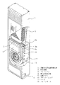
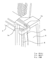
図1は、本発明の実施形態1に係る床置き式空気調和機の内部構成を示す斜視図である。また図2は、図1に示す床置き式空気調和機のドレインパンに設けられた溢流口の周辺部を示す拡大斜視図である。なお図1及び図2では、床置き式空気調和機の内部が見えるように一部を透明にしており、また溢流口の周辺部が見えるように一部を点線で示している。
図1に示す床置き式空気調和機は、床置き式空気調和機本体1の内部上方に熱交換器2を備え、その下方に熱交換器2から発生したドレイン(排水)を収容するドレインパン3が設けられている。また本実施形態1では、ドレインパン3の直下に電気部品を収容する電気部品収容箱4が備えられている。なおこの電気部品は、熱交換器2や以下に示す送風ファン5等を制御するためのものである。
FIG. 1 is a perspective view showing an internal configuration of a floor-standing air conditioner according to
The floor-standing air conditioner shown in FIG. 1 is provided with a
さらにドレインパン3の下部には、熱交換器2から発生した冷風又は温風を送風するための送風ファン5を収容するファンケーシング6が備えられている。なお本実施形態1では、図1に示すように、電気部品収容箱4が床置き式空気調和機本体1内部の前面側に設けられ、ファンケーシング6が床置き式空気調和機本体1内部の背面側に設けられているものとする。また、床置き式空気調和機本体1の最下部には、底面を形成するベース7が設けられている。なお送風ファン5は、例えば電動モータにより回転して熱交換器2から発生した冷風又は温風を送風するようになっている。
Furthermore, a
図1に示す床置き式空気調和機は、床置き式空気調和機本体1の前面上方に設けられた吸込口(符号なし)から送風ファン5によって空気を吸引し、その空気が熱交換器2を通過する。この際、熱交換器2は空気を冷却又は加熱することにより冷風又は温風を発生する。熱交換器2で発生した冷風又は温風は、送風ファン5によって床置き式空気調和機本体1の前面下方に設けられた吹出口(符号なし)から送風される。
The floor-standing air conditioner shown in FIG. 1 sucks air by a
図2に示すように、本実施形態1に係る床置き式空気調和機のドレインパン3の底面には、排水口3aが設けられており、この排水口3aにはドレインホース8が接続されている。またドレインパン3の側壁の上方には、切り欠き状の溢水口3bが設けられている。なお本実施形態1では、溢水口3bは床置き式空気調和機本体1の背面側に設けられているものとする。また溢水口3bの切り欠きの形状は、任意の形状でよい。
またファンケーシング6の側面には、ファンケーシング6を凹状に加工した水路6aが形成されており、この水路6aはドレインパン3に設けられた溢水口3bと繋がるように配置されている。なお従来の一般的な床置き式空気調和機では、溢水口3b及び水路6aに相当するものは設けられていない。
As shown in FIG. 2, a
Further, a
本実施形態1に係る床置き式空気調和機では、床置き式空気調和機本体1の内部上方に備えられた熱交換器2から発生したドレインが、熱交換器2の下部に設けられたドレインパン3に流下する。通常の場合、ドレインパン3に流下したドレインは、排水口3aからドレインホース8を通って床置き式空気調和機本体1の外部に排出される。
しかし、排水口3aやドレインホース8に詰まりが発生した場合には、ドレインパン3に水(ドレイン)が溜まり、この水がドレインパン3に設けられた溢水口3bから流出する。流出した水は、ファンケーシンング6の側面に凹状に形成された水路6aに沿って流下し、床置き式空気調和機本体1の最下部を形成するベース7に流れ落ちる。
In the floor-standing air conditioner according to the first embodiment, the drain generated from the
However, when the
なお本実施形態1では、電気部品を収容する電気部品収容箱4が床置き式空気調和機本体1の前面側に設けられ、溢水口3bが床置き式空気調和機本体1の背面側に設けられているが、電気部品を収容する電気部品収容箱4を床置き式空気調和機本体1の背面側に設け、溢水口3bを床置き式空気調和機本体1の前面側に設けるようにしてもよい。このように、溢水口3bと電気部品を収容する電気部品収容箱4を離れた位置に配置することで、電気部品への水着を確実に防止することができる。
In the first embodiment, the electrical
本実施形態1では、ドレインパン3が切り欠き状の溢流口3bを有し、ファンケーシング6が溢流口3bから溢れ出た水を流下させる水路6aを有するため、ドレインパン3の下部に設けられた電気部品や送風ファン6への水着を防止することができ、水に対する安全性が確保できる。また水の浸入を防止するための電気部品収容箱4に貼付されたシール材を省略することができるため、コストが抑えられ安価な床置き式空気調和機を提供することが可能となる。
また、溢水口3bから溢れ出た水を流下させる水路6aがファンケーシング6の側面に凹状に形成されているため、溢水口3bから溢れ出た水がファンケーシング6の側面に沿って流下し、水が送風ファン5に掛かるのを防止することができる。
さらに電気部品収容箱4がドレインパン3の直下に設けられているため、溢水口3bから溢れ出た水が電気部品に掛かる危険性を低減することができる。
In the first embodiment, the
Further, since the
Furthermore, since the electrical
なお本発明に係る床置き式空気調和機は、上記の実施形態に限定されるものではなく、本発明の思想の範囲内において変更することが可能である。例えば、ファンケーシング6に設けられた水路6aは、ホース状のものであってもよい。
The floor-standing air conditioner according to the present invention is not limited to the above-described embodiment, and can be changed within the scope of the idea of the present invention. For example, the
1 床置き式空気調和機本体、2 熱交換器、3 ドレインパン、3a 排水口、3b 溢水口、4 電気部品収容箱、5 送風ファン、6 ファンケーシング、6a 水路、7 ベース、8 ドレインホース。
1 floor-mounted air conditioner body, 2 heat exchanger, 3 drain pan, 3a drainage port, 3b overflow port, 4 electrical component storage box, 5 blower fan, 6 fan casing, 6a waterway, 7 base, 8 drain hose.
Claims (4)
前記ドレインパンは、床置き式空気調和機本体の背面側に形成された切り欠き状の溢流口を有し、前記ファンケーシングは、前記ファンケーシングの側面を凹状に加工して形成され前記溢流口から溢れ出た水を流下させる水路を有することを特徴とする床置き式空気調和機。 A heat exchanger, a drain pan provided in a lower portion of the heat exchanger, which accommodates a drain generated from the heat exchanger, and a blowout port provided with cool air or hot air generated from the heat exchanger below the front surface A blower fan for blowing air from, a fan casing provided at a lower part of the drain pan and containing the blower fan, and provided on a front side of a floor-standing air conditioner directly under the drain pan, the heat exchanger And an electrical component for controlling the blower fan ,
The drain pan has a notch-shaped overflow port formed on the back side of the floor-standing air conditioner body, and the fan casing is formed by processing a side surface of the fan casing into a concave shape. A floor-standing air conditioner characterized by having a water channel for flowing down water overflowing from an outlet.
前記排水口にはドレインホースが接続されていることを特徴とする請求項1〜3のいずれかに記載の床置き式空気調和機。 The floor-standing air conditioner according to any one of claims 1 to 3, wherein a drain hose is connected to the drain port.
Priority Applications (2)
| Application Number | Priority Date | Filing Date | Title |
|---|---|---|---|
| JP2005080112A JP4628152B2 (en) | 2005-03-18 | 2005-03-18 | Floor-mounted air conditioner |
| CNB2005101160969A CN100417872C (en) | 2005-03-18 | 2005-10-28 | Floor type air-conditioner |
Applications Claiming Priority (1)
| Application Number | Priority Date | Filing Date | Title |
|---|---|---|---|
| JP2005080112A JP4628152B2 (en) | 2005-03-18 | 2005-03-18 | Floor-mounted air conditioner |
Publications (3)
| Publication Number | Publication Date |
|---|---|
| JP2006258405A JP2006258405A (en) | 2006-09-28 |
| JP2006258405A5 JP2006258405A5 (en) | 2008-03-27 |
| JP4628152B2 true JP4628152B2 (en) | 2011-02-09 |
Family
ID=37002396
Family Applications (1)
| Application Number | Title | Priority Date | Filing Date |
|---|---|---|---|
| JP2005080112A Expired - Fee Related JP4628152B2 (en) | 2005-03-18 | 2005-03-18 | Floor-mounted air conditioner |
Country Status (2)
| Country | Link |
|---|---|
| JP (1) | JP4628152B2 (en) |
| CN (1) | CN100417872C (en) |
Families Citing this family (3)
| Publication number | Priority date | Publication date | Assignee | Title |
|---|---|---|---|---|
| JP2008175456A (en) * | 2007-01-18 | 2008-07-31 | Sanyo Electric Co Ltd | Air conditioner installed on floor |
| WO2017017814A1 (en) * | 2015-07-29 | 2017-02-02 | 三菱電機株式会社 | Heat exchanger and refrigeration cycle apparatus |
| CN109520112A (en) * | 2018-11-13 | 2019-03-26 | 珠海格力电器股份有限公司 | Drip tray and air conditioner |
Citations (3)
| Publication number | Priority date | Publication date | Assignee | Title |
|---|---|---|---|---|
| JPS63110834U (en) * | 1987-01-09 | 1988-07-16 | ||
| JPH06201149A (en) * | 1992-12-28 | 1994-07-19 | Sanyo Electric Co Ltd | Air-conditioner |
| JPH09269138A (en) * | 1996-03-29 | 1997-10-14 | Mitsubishi Heavy Ind Ltd | Wall recessed type air-conditioner |
Family Cites Families (4)
| Publication number | Priority date | Publication date | Assignee | Title |
|---|---|---|---|---|
| US5511386A (en) * | 1994-11-23 | 1996-04-30 | Carrier Corporation | Adjustable pitch condensate drain with integral overflow |
| KR100191532B1 (en) * | 1996-09-12 | 1999-06-15 | 윤종용 | Drain water sense device and method by room temperature sensor of airconditioner |
| CN2374791Y (en) * | 1999-01-12 | 2000-04-19 | 广东美的集团股份有限公司 | Air conditioner with condensed water guider |
| CN1356515A (en) * | 2001-12-26 | 2002-07-03 | 乐金电子(天津)电器有限公司 | Water discharge unit of seiling-tyupe air conditioner |
-
2005
- 2005-03-18 JP JP2005080112A patent/JP4628152B2/en not_active Expired - Fee Related
- 2005-10-28 CN CNB2005101160969A patent/CN100417872C/en active Active
Patent Citations (3)
| Publication number | Priority date | Publication date | Assignee | Title |
|---|---|---|---|---|
| JPS63110834U (en) * | 1987-01-09 | 1988-07-16 | ||
| JPH06201149A (en) * | 1992-12-28 | 1994-07-19 | Sanyo Electric Co Ltd | Air-conditioner |
| JPH09269138A (en) * | 1996-03-29 | 1997-10-14 | Mitsubishi Heavy Ind Ltd | Wall recessed type air-conditioner |
Also Published As
| Publication number | Publication date |
|---|---|
| JP2006258405A (en) | 2006-09-28 |
| CN1834547A (en) | 2006-09-20 |
| CN100417872C (en) | 2008-09-10 |
Similar Documents
| Publication | Publication Date | Title |
|---|---|---|
| JP4862814B2 (en) | Air conditioner outdoor unit | |
| JP2011094926A (en) | Outdoor unit for air conditioner | |
| JP4628152B2 (en) | Floor-mounted air conditioner | |
| TWI674381B (en) | Refrigeration unit heat source unit | |
| JP4761894B2 (en) | Drain drainage device for heat exchange unit for heat pump water heater | |
| JP2007322103A (en) | Air conditioner | |
| JP2010281461A (en) | Outdoor unit for air conditioner | |
| KR20070028884A (en) | Air conditioner incorporated evaporator and condenser in one body | |
| KR100654729B1 (en) | Front cover guide panel for preventing flooding a display control box of a package air-conditioner | |
| JP2011112336A (en) | Ceiling embedded type air conditioner | |
| KR20030042713A (en) | Airguide-assembly for airconditioner | |
| JP5511414B2 (en) | Hot water supply outdoor unit | |
| JP4984646B2 (en) | Air conditioner indoor unit | |
| KR100575305B1 (en) | Drain Pan for air conditioner | |
| JPH1068535A (en) | Integral type air conditioner | |
| CN213334892U (en) | Shell assembly and dehumidifier | |
| KR100389422B1 (en) | A saturation water drain structure for air conditioner | |
| CN218784379U (en) | Pot subassembly and kitchen equipment | |
| JP3831880B2 (en) | Cooling unit | |
| KR20030000209A (en) | Saturation water drain structure for air conditioner | |
| CN111837002B (en) | Indoor unit of air conditioner | |
| JP5232667B2 (en) | Embedded ceiling air conditioner | |
| JP2002276977A (en) | Floor-type air conditioner | |
| WO2019142462A1 (en) | Ceiling-embedded air conditioner | |
| KR100564485B1 (en) | Indoor unit for air conditioner |
Legal Events
| Date | Code | Title | Description |
|---|---|---|---|
| A521 | Written amendment |
Free format text: JAPANESE INTERMEDIATE CODE: A523 Effective date: 20080213 |
|
| A621 | Written request for application examination |
Free format text: JAPANESE INTERMEDIATE CODE: A621 Effective date: 20080213 |
|
| A977 | Report on retrieval |
Free format text: JAPANESE INTERMEDIATE CODE: A971007 Effective date: 20100707 |
|
| A131 | Notification of reasons for refusal |
Free format text: JAPANESE INTERMEDIATE CODE: A131 Effective date: 20100713 |
|
| A521 | Written amendment |
Free format text: JAPANESE INTERMEDIATE CODE: A523 Effective date: 20100908 |
|
| TRDD | Decision of grant or rejection written | ||
| A01 | Written decision to grant a patent or to grant a registration (utility model) |
Free format text: JAPANESE INTERMEDIATE CODE: A01 Effective date: 20101102 |
|
| A01 | Written decision to grant a patent or to grant a registration (utility model) |
Free format text: JAPANESE INTERMEDIATE CODE: A01 |
|
| A61 | First payment of annual fees (during grant procedure) |
Free format text: JAPANESE INTERMEDIATE CODE: A61 Effective date: 20101109 |
|
| FPAY | Renewal fee payment (event date is renewal date of database) |
Free format text: PAYMENT UNTIL: 20131119 Year of fee payment: 3 |
|
| R150 | Certificate of patent or registration of utility model |
Free format text: JAPANESE INTERMEDIATE CODE: R150 |
|
| R250 | Receipt of annual fees |
Free format text: JAPANESE INTERMEDIATE CODE: R250 |
|
| R250 | Receipt of annual fees |
Free format text: JAPANESE INTERMEDIATE CODE: R250 |
|
| R250 | Receipt of annual fees |
Free format text: JAPANESE INTERMEDIATE CODE: R250 |
|
| LAPS | Cancellation because of no payment of annual fees |