JP4628126B2 - Round sash mounting structure - Google Patents
Round sash mounting structure Download PDFInfo
- Publication number
- JP4628126B2 JP4628126B2 JP2005033177A JP2005033177A JP4628126B2 JP 4628126 B2 JP4628126 B2 JP 4628126B2 JP 2005033177 A JP2005033177 A JP 2005033177A JP 2005033177 A JP2005033177 A JP 2005033177A JP 4628126 B2 JP4628126 B2 JP 4628126B2
- Authority
- JP
- Japan
- Prior art keywords
- sash
- round
- opening
- frame
- mounting structure
- Prior art date
- Legal status (The legal status is an assumption and is not a legal conclusion. Google has not performed a legal analysis and makes no representation as to the accuracy of the status listed.)
- Expired - Lifetime
Links
Images
Landscapes
- Load-Bearing And Curtain Walls (AREA)
- Door And Window Frames Mounted To Openings (AREA)
Description
本発明は、建物の開口部に取り付けられてなる丸形サッシの取付構造に関する。 The present invention relates to a mounting structure for a round sash attached to an opening of a building.
例えば、建物の外壁に丸形窓を取り付ける場合、円形状にくり抜かれた開口部が形成された壁面材を間柱と水平材との間に設置して、その円形状の開口部に円筒状の取付枠を取
り付け、さらに、その取付枠に円筒状の丸窓を嵌め込むことによって取り付けている(例えば、特許文献1参照)。また、取付枠の端面と壁面材との間の境界部分には止水材(防水シート等)を設けて水密にしており、さらに、取付枠と丸窓との間の境界部分にも止水材を設けて水密にしている。
しかしながら、上記特許文献1に記載の丸形窓の取付構造において、壁面材の開口部に取り付けられる取付枠と、この取付枠に嵌め込まれる丸形窓とは、ともに円筒状をなしているので、壁面材と取付枠との間の境界部分及び取付枠と丸形窓との間の境界部分に、それぞれ止水材を円形状に設けなければならず、止水材を矩形状に設ける場合に比して、その作業が煩雑で手間がかかるという問題があった。
本発明は、上記事情に鑑みてなされたもので、施工が容易で、防水性能に優れた丸形サッシの取付構造を提供することを目的としている。
However, in the mounting structure of the round window described in Patent Document 1, since the mounting frame attached to the opening of the wall material and the round window fitted into the mounting frame are both cylindrical, When the water stop material must be provided in a circular shape at the boundary portion between the wall material and the mounting frame and the boundary portion between the mounting frame and the round window, respectively, when the water stop material is provided in a rectangular shape In comparison, there is a problem that the work is complicated and time-consuming.
The present invention has been made in view of the above circumstances, and an object thereof is to provide a mounting structure for a round sash that is easy to construct and excellent in waterproof performance.
上記課題を解決するため、請求項1の発明は、例えば、図1〜図4に示すように、建物1の開口部Kに取り付けられてなる丸形サッシ3の取付構造であって、
前記開口部Kが矩形状をなしており、
この開口部Kに固定される矩形枠状のサッシ枠部4と、該サッシ枠部4の内側に一体に形成されて内部に窓部材6が嵌め込まれる円環状の窓支持部5とを有する丸形サッシ3が、前記サッシ枠部4を前記開口部Kに固定することによって取り付けられ、
前記サッシ枠部4が、矩形枠状の枠体部41の表面にフランジ部42が一体形成されたものであり、
前記フランジ部42が、前記開口部Kが形成された壁パネル2の外壁面2aに当接し、
前記フランジ部42と前記壁パネル2の外壁面2との境界部分に、該境界部分を覆うように防水シート11が矩形枠状に設けられていることを特徴とする。
In order to solve the above problems, the invention of claim 1 is an attachment structure for a round sash 3 attached to an opening K of a building 1, for example, as shown in FIGS.
The opening K has a rectangular shape;
A round frame having a rectangular frame-shaped
The
The
The waterproof sheet 11 is provided in a rectangular frame shape so as to cover the boundary portion between the
請求項1の発明によれば、矩形状の開口部Kに固定される矩形枠状のサッシ枠部4と、サッシ枠部4の内側に形成されて内部に窓部材6が嵌め込まれる円環状の窓支持部5とを有する丸形サッシ3が、サッシ枠部4を開口部Kに固定することによって取り付けられ、開口部K周囲の壁面2aとサッシ枠部4との境界部分に、該境界部分を覆うように防水部材11が設けられているので、矩形状の開口部Kに矩形枠状のサッシ枠部4を取り付け、開口部K周囲の壁面2aとサッシ枠部4との間に防水シート11等の防水部材を矩形枠状に設ければ良いため、その作業が容易で施工を短縮でき、防水性能に優れた構造とすることができる。
According to the invention of claim 1, a rectangular frame-shaped
請求項2の発明は、例えば、図1〜図4に示すように、請求項1に記載の丸形サッシ3の取付構造において、
前記サッシ枠部4と前記窓支持部5とは樹脂製であることを特徴とする。
As for invention of
The
請求項2の発明によれば、サッシ枠部4と窓支持部5とは樹脂製であるので、成形が容易で、また、一体成形が可能となる。しかも、アルミニウム製に比べて断熱性能に優れる。
According to the invention of
請求項3の発明は、例えば、図2、図3に示すように、請求項1又は2に記載の丸形サッシ3の取付構造において、
前記開口部Kに、前記丸形サッシ3の裏面から前記開口部K周囲の内壁面2bに跨るように化粧枠9が取り付けられていることを特徴とする。
The invention of claim 3 is, for example, as shown in FIGS. 2 and 3, in the mounting structure of the round sash 3 according to
A decorative frame 9 is attached to the opening K so as to straddle the inner wall surface 2b around the opening K from the back surface of the round sash 3.
請求項3の発明によれば、開口部Kに丸形サッシ3の裏面から開口部K周囲の内壁面2bに跨るように化粧枠9が取り付けられているので、この化粧枠9によって丸形サッシ3が覆われて室内側から見えることがなく、意匠面で優れる。 According to the invention of claim 3, the decorative frame 9 is attached to the opening K so as to straddle the inner wall surface 2 b around the opening K from the back surface of the round sash 3. 3 is covered and is not visible from the indoor side, and is excellent in terms of design.
請求項4の発明は、例えば、図5に示すように、請求項1〜3のいずれか一項に記載の丸形サッシ3の取付構造において、
前記丸形サッシ3の裏面に断熱材Dが設けられていることを特徴とする。
The invention of
A heat insulating material D is provided on the back surface of the round sash 3.
請求項4の発明によれば、丸形サッシ3の裏面に断熱材Dが設けられているので、断熱性に非常に優れた構造とすることができる。
According to invention of
請求項5の発明は、例えば、図2〜図3に示すように、請求項1〜4のいずれか一項に記載の丸形サッシ3の取付構造において、
前記開口部Kを形成する内周面Kaと前記サッシ枠部4との間に調整材14が設けられていることを特徴とする。
The invention of
An
請求項5の発明によれば、開口部Kを形成する内周面Kaとサッシ枠部4との間に調整材14が設けられているので、この調整材14によって丸形サッシ3を取り付けた際のがたつきを防止することができ、丸形サッシ3を開口部Kに強固でかつ確実に取り付けることができる。
According to the invention of
本発明に係る丸形サッシの取付構造によれば、矩形状の開口部に、円環状の窓支持部が形成された矩形枠状のサッシ枠部を取り付け、防水部材を開口部周囲の壁面とサッシ枠部との間の境界部分に矩形枠状に設ければ良いため、その作業が容易で施工を短縮でき、防水性能に優れた構造とすることができる。 According to the mounting structure of the round sash according to the present invention, a rectangular frame-shaped sash frame portion in which an annular window support portion is formed is attached to the rectangular opening portion, and the waterproof member is attached to the wall surface around the opening portion. Since it suffices to provide a rectangular frame at the boundary between the sash frame and the sash frame, the work is easy, the construction can be shortened, and a waterproof structure can be obtained.
以下、本発明の実施の形態について図面を参照しながら説明する。
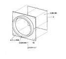
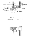
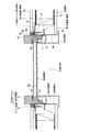
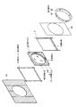
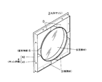
図1は、本発明の実施の形態の丸形サッシの斜視図、図2は丸形サッシの取付構造を示した縦断面図、図3は、丸形サッシの取付構造を示した横断面図、図4は、図2及び図3における分解斜視図である。
図1〜図3に示すように、本実施の形態における建物1は、パネル工法により構築されており、パネル工法とは、予め工場等で製造された木質パネルを現場で基礎に組み付けていくことにより、住宅の床、壁、屋根等を構築するものである。そして、この建物1を構成する壁パネル2には矩形状の開口部Kが形成され、開口部Kに丸形サッシ3が取り付けられている。
Hereinafter, embodiments of the present invention will be described with reference to the drawings.
1 is a perspective view of a round sash according to an embodiment of the present invention, FIG. 2 is a longitudinal sectional view showing a mounting structure of the round sash, and FIG. 3 is a transverse sectional view showing a mounting structure of the round sash. 4 is an exploded perspective view of FIGS. 2 and 3.
As shown in FIGS. 1-3, the building 1 in this Embodiment is constructed | assembled by the panel construction method, and the panel construction method assemble | attaches the wood panel manufactured beforehand by the factory etc. to the foundation on the spot. Thus, the floor, wall, roof, etc. of the house are constructed. A rectangular opening K is formed in the
丸形サッシ3は、開口部Kに固定される矩形枠状のサッシ枠部4と、このサッシ枠部4の内側に一体に形成されて内部に丸形状の窓部材6が嵌め込まれる円環状の窓支持部5とを有している。
これらサッシ枠部4及び窓支持部5は、ともにFRP樹脂等の樹脂を材料とし、この樹脂材料を押出成形することによって一体成形されている。
The round sash 3 is an annular
Both the
サッシ枠部4は、矩形枠状の枠体部41の表面に板状のフランジ部42が一体に形成されてなり(図4参照)、フランジ部42が壁パネル2の外壁面2aに当接するとともに、枠体部41が開口部Kの内周面Kaに当接するように開口部Kに配置されている。そして、フランジ部42から壁パネル2の外壁面2aに向けてネジNがねじ込まれ、枠体部41から開口部Kの内周面Kaに向けてネジNがねじ込まれることによって、丸形サッシ3が開口部Kに固定されている。なお、枠体部41と開口部Kの上面、左右側面との間には、調整材14が介されてネジ止めされている。
The
また、このサッシ枠部4の内側に一体に形成された窓支持部5は、フランジ部42の表面及び裏面からそれぞれ突出して設けられている。
窓支持部5の中央には円形状の嵌合穴51が形成されており、この嵌合穴51に丸形状の窓部材6が嵌め込まれている。
Further, the
A
窓部材6は、窓フレーム61と窓ガラス62とを備え、窓ガラス62は二重ガラスとなっている。
この窓部材6は、窓支持部5の裏面側から嵌合穴51に嵌め込まれて、断面視略L字型の取付部材7を介して窓支持部5にネジ止めされている。また、嵌合穴51に嵌め込まれた窓部材6は、その表面側の周縁部が窓支持部5に覆われて、さらに、その窓部材6の表面側の周縁部と窓支持部5との間には、防水をとるためのパッキン材8aが充填されている。
The window member 6 includes a
The window member 6 is fitted into the
このようにして丸形サッシ3が取り付けられた開口部Kには、丸形サッシ3の裏面から壁パネル2の内壁面2bに跨って、丸形サッシ3を覆うように化粧枠9が取り付けられている。
化粧枠9は、円環状の化粧枠体部91の裏面に化粧フランジ部92が一体に形成されてなり(図4参照)、化粧枠体部91の先端部が窓部材6に当接するとともに、化粧フランジ部92の先端部が壁パネル2の内壁面2bである石膏ボード10に当接している。
A decorative frame 9 is attached to the opening K to which the round sash 3 is attached in this manner so as to cover the round sash 3 from the back surface of the round sash 3 to the inner wall surface 2b of the
The decorative frame 9 is formed by integrally forming a decorative flange portion 92 on the back surface of the annular decorative frame body portion 91 (see FIG. 4), the front end portion of the decorative frame body portion 91 abuts the window member 6, and The front end portion of the decorative flange portion 92 is in contact with the
一方、壁パネル2の外壁面2aに固定されたサッシ枠部41におけるフランジ部42と外壁面2aとの境界部分に、該境界部分を覆うようにして防水シート(防水部材)11がフランジ部42の周縁部に沿って矩形枠状に貼り付けられている。
防水シート11としては、例えば、両面ゴムアステープ等を使用することが好ましい。 そして、この防水シート11の表面に胴縁12が取り付けられ、胴縁12の表面に外装材13が取り付けられている。この外装材13の開口部K側の端部には、丸形サッシ3の窓支持部5との防水をとるためのパッキン材8bが充填されている。
On the other hand, the waterproof sheet (waterproof member) 11 is provided at the boundary portion between the
As the waterproof sheet 11, it is preferable to use, for example, double-sided rubber as tape. A
次に、上述の丸形サッシ3を開口部Kに取り付ける丸形サッシ3の取付方法について説明する。
図2〜図4に示すように、予め、窓支持部5の嵌合穴51に窓部材6を嵌め込み、取付部材7を介してネジ止めすることによって窓部材6を丸形サッシ3に固定しておく。
次いで、この丸形サッシ3を、サッシ枠部4のフランジ部42を壁パネル2の外壁面2aに、枠体部41を開口部Kの内周面Kaに当接させて配置する。そして、フランジ部42から壁パネル2の外壁面2aに、枠体部41から開口部Kの内周面Kaに向けてネジNをねじ込むことによって丸形サッシ3を開口部Kに固定する。なお、枠体部41を開口部Kの上面及び左右側面に固定する場合には、調整材14を介してネジ止めする。
その後、丸形サッシ3の裏面から開口部Kの内壁面Kaに跨って、丸形サッシ3を覆うように化粧枠10を取り付ける。
Next, a method for attaching the round sash 3 for attaching the round sash 3 to the opening K will be described.
As shown in FIG. 2 to FIG. 4, the window member 6 is previously fitted in the
Next, the round sash 3 is disposed with the
Thereafter, the
一方、室外側において、サッシ枠部4のフランジ部42の表面に、外壁面2aに跨るようにして矩形枠状に防水シート11を貼り付ける。さらに、この防水シート11の表面に胴縁12を取り付け、胴縁12の表面に外装材13を取り付ける。この際に、外装材13の開口部K側の端部と窓支持部5との間にパッキン材8bを充填する。パッキン材8bは、防水シート11上に接着剤等を塗布することにより充填する。
On the other hand, on the outdoor side, the waterproof sheet 11 is attached to the surface of the
以上、本発明の実施の形態における丸形サッシ3の取付構造によれば、壁パネル2の矩形状の開口部Kに、矩形枠状のサッシ枠部4と、サッシ枠部4の内側に一体に形成された円環状の窓支持部5とを有する丸形サッシ3が、サッシ枠部4のフランジ部42及び枠体部41を開口部Kにそれぞれ固定することによって取り付けられ、外壁面2aとフランジ部42との境界部分に、その境界部分を覆うようにして防水シート11が貼り付けられているので、従来と異なり、防水シート11をその境界部分に矩形枠状に貼り付ければ良く、その作業が容易で施工を短縮でき、防水性能に優れた構造とすることができる。
As described above, according to the mounting structure of the round sash 3 in the embodiment of the present invention, the rectangular opening K of the
また、サッシ枠部4と窓支持部5とは樹脂製で一体成形されていることから、これらサッシ枠部4と窓支持部5とを同時に製造でき、サッシ枠部4に窓支持部5を嵌め込んで設置するといった作業を省くことができる。また、サッシ枠部4と窓支持部5とが別体である場合に比べて、サッシ枠部4と窓支持部5との嵌め込み部分等の複雑な部分の防水が完全になり、嵌め込み部分に防水シート11を貼り付ける必要もない。よって、サッシ枠部4と外壁面2aとの境界部分のみに矩形枠状に防水シート11を貼り付ければ良く、この点においても施工が非常に容易となる。
また、樹脂材料からなるので、その成形も容易で、コストを低減できる。さらに、アルミニウム製に比べて断熱性能に優れる。
Further, since the
Moreover, since it consists of a resin material, the shaping | molding is easy and can reduce cost. Furthermore, it has excellent heat insulation performance compared to aluminum.
開口部Kに丸形サッシ3の裏面から壁パネル2の内壁面2bに跨るように化粧枠9が取り付けられているので、この化粧枠9によって丸形サッシ3が覆われて室内側から見えることがなく、意匠面で優れる。
また、開口部Kの上面及び左右側面とサッシ枠部4のフランジ部42との間に調整材14が設けられているので、丸形サッシ3を取り付けた際のがたつきを防止することができ、丸形サッシ3を開口部Kに強固でかつ確実に取り付けることができる。
Since the decorative frame 9 is attached to the opening K so as to straddle the back surface of the round sash 3 from the inner wall surface 2b of the
Further, since the adjusting
なお、本発明は、上記実施の形態に限定されるものではなく、その要旨を逸脱しない範囲で適宜変更可能である。
例えば、上記実施の形態における丸形サッシ3の断熱性能を向上させるために、図5に示すように、丸形サッシ3の裏面、すなわち、サッシ枠部4のフランジ部42の裏面で枠体部41の内部に、窓部材6を囲むように断熱材Dを設けても良い。
In addition, this invention is not limited to the said embodiment, In the range which does not deviate from the summary, it can change suitably.
For example, in order to improve the heat insulation performance of the round sash 3 in the above embodiment, as shown in FIG. A heat insulating material D may be provided inside 41 so as to surround the window member 6.
また、サッシ枠部4はフランジ部42と枠体部41とから構成され、フランジ部42が壁パネル2の外壁面2aに固定され、枠体部41が開口部Kの内周面Kaに固定され、丸形サッシ3のうちの2箇所を開口部Kに固定するとしたが、これに限らず、例えば、サッシ枠部4をフランジ部42のみから構成し、フランジ部42の1箇所で固定するものとしても良いし、サッシ枠部4を枠体部41のみから構成し、枠体部41の1箇所で固定するものとしても良い。
The
さらに、上記サッシ枠部4と窓支持部5とは樹脂材料を押出成形により一体成形するとしたが、サッシ枠部4と窓支持部5とは別体としても構わない。
Further, although the
1 建物
2a 外壁面(壁面)
2b 内壁面(壁面)
3 丸形サッシ
4 サッシ枠部
5 窓支持部
6 窓部材
9 化粧枠
11 防水シート(防水部材)
14 調整材
D 断熱材
K 開口部
Ka 内周面
1 Building 2a Exterior wall (wall)
2b Inner wall surface (wall surface)
DESCRIPTION OF SYMBOLS 3
14 Adjustment material D Heat insulation material K Opening part Ka Inner peripheral surface
Claims (5)
前記開口部が矩形状をなしており、
この開口部に固定される矩形枠状のサッシ枠部と、該サッシ枠部の内側に一体に形成されて内部に窓部材が嵌め込まれる円環状の窓支持部とを有する丸形サッシが、前記サッシ枠部を前記開口部に固定することによって取り付けられ、
前記サッシ枠部が、矩形枠状の枠体部の表面にフランジ部が一体形成されたものであり、
前記フランジ部が、前記開口部が形成された壁パネルの外壁面に当接し、
前記フランジ部と前記壁パネルの外壁面との境界部分に、該境界部分を覆うように防水シートが矩形枠状に設けられていることを特徴とする丸形サッシの取付構造。 A mounting structure of a round sash attached to the opening of a building,
The opening has a rectangular shape;
A round sash having a rectangular frame-shaped sash frame portion fixed to the opening, and an annular window support portion integrally formed inside the sash frame portion and into which a window member is fitted. It is attached by fixing the sash frame to the opening,
The sash frame portion is formed by integrally forming a flange portion on the surface of a rectangular frame-shaped frame body portion,
The flange portion is in contact with the outer wall surface of the wall panel in which the opening is formed;
A mounting structure for a round sash, wherein a waterproof sheet is provided in a rectangular frame shape so as to cover the boundary portion between the flange portion and the outer wall surface of the wall panel .
前記サッシ枠部と前記窓支持部とは樹脂製であることを特徴とする丸形サッシの取付構造。 In the mounting structure of the round sash of Claim 1,
The mounting structure for a round sash, wherein the sash frame portion and the window support portion are made of resin.
前記開口部に、前記丸形サッシの裏面から前記開口部周囲の内壁面に跨るように化粧枠が取り付けられていることを特徴とする丸形サッシの取付構造。 In the mounting structure of the round sash of Claim 1 or 2,
A mounting structure for a round sash, wherein a decorative frame is attached to the opening so as to straddle the inner wall surface around the opening from the back surface of the round sash.
前記丸形サッシの裏面に断熱材が設けられていることを特徴とする丸形サッシの取付構造。 In the mounting structure of the round sash as described in any one of Claims 1-3,
A mounting structure for a round sash, wherein a heat insulating material is provided on the back surface of the round sash.
前記開口部を形成する内周面と前記サッシ枠部との間に調整材が設けられていることを特徴とする丸形サッシの取付構造。 In the mounting structure of the round sash as described in any one of Claims 1-4,
A mounting structure for a round sash, wherein an adjusting material is provided between an inner peripheral surface forming the opening and the sash frame.
Priority Applications (1)
| Application Number | Priority Date | Filing Date | Title |
|---|---|---|---|
| JP2005033177A JP4628126B2 (en) | 2005-02-09 | 2005-02-09 | Round sash mounting structure |
Applications Claiming Priority (1)
| Application Number | Priority Date | Filing Date | Title |
|---|---|---|---|
| JP2005033177A JP4628126B2 (en) | 2005-02-09 | 2005-02-09 | Round sash mounting structure |
Publications (2)
| Publication Number | Publication Date |
|---|---|
| JP2006219873A JP2006219873A (en) | 2006-08-24 |
| JP4628126B2 true JP4628126B2 (en) | 2011-02-09 |
Family
ID=36982378
Family Applications (1)
| Application Number | Title | Priority Date | Filing Date |
|---|---|---|---|
| JP2005033177A Expired - Lifetime JP4628126B2 (en) | 2005-02-09 | 2005-02-09 | Round sash mounting structure |
Country Status (1)
| Country | Link |
|---|---|
| JP (1) | JP4628126B2 (en) |
Families Citing this family (1)
| Publication number | Priority date | Publication date | Assignee | Title |
|---|---|---|---|---|
| JP2007146576A (en) * | 2005-11-30 | 2007-06-14 | Ykk Ap株式会社 | Window equipment |
Family Cites Families (3)
| Publication number | Priority date | Publication date | Assignee | Title |
|---|---|---|---|---|
| JPS4412358Y1 (en) * | 1965-03-27 | 1969-05-23 | ||
| JP3835733B2 (en) * | 2000-12-15 | 2006-10-18 | 今井 淑夫 | Finishing method and structure of interior materials |
| JP2003184434A (en) * | 2001-12-20 | 2003-07-03 | Sekisui House Ltd | Round window structure |
-
2005
- 2005-02-09 JP JP2005033177A patent/JP4628126B2/en not_active Expired - Lifetime
Also Published As
| Publication number | Publication date |
|---|---|
| JP2006219873A (en) | 2006-08-24 |
Similar Documents
| Publication | Publication Date | Title |
|---|---|---|
| JP4628126B2 (en) | Round sash mounting structure | |
| JP6487199B2 (en) | Decorative material | |
| KR101819716B1 (en) | Assembling awning | |
| JP4046344B2 (en) | Combination window | |
| JP2006348672A (en) | Building eaves | |
| KR102018426B1 (en) | Dividing window being easy to adjust and assemble | |
| JP3994972B2 (en) | Fence body and fence | |
| JP3211059B2 (en) | Window frame made of synthetic resin | |
| JP2018016992A (en) | Independent structure | |
| JP4111496B2 (en) | Sash mounting structure | |
| JP6367028B2 (en) | Mounting structure of support member | |
| JP5074263B2 (en) | Decorative frame mounting structure and decorative frame | |
| JP3155117B2 (en) | Corner store front | |
| JP4981710B2 (en) | Heat insulation fittings | |
| KR200283678Y1 (en) | Composition window frame | |
| JP7059142B2 (en) | Continuous windows | |
| JP3174714B2 (en) | Framework system for decorative unit frame | |
| JP2818093B2 (en) | Outer wall panel waterproof structure | |
| JP3812893B2 (en) | Composite window frame connection structure | |
| JPS597991Y2 (en) | Assembly structure of small window with muntins | |
| JP4246860B2 (en) | Panel mounting structure for buildings, etc. | |
| JP4099280B2 (en) | Building opening member and its construction method | |
| JPH0516344Y2 (en) | ||
| JP2006138131A (en) | Corner member for ceiling cornice part | |
| JP3972339B2 (en) | Outdoor structure |
Legal Events
| Date | Code | Title | Description |
|---|---|---|---|
| A621 | Written request for application examination |
Free format text: JAPANESE INTERMEDIATE CODE: A621 Effective date: 20070706 |
|
| A711 | Notification of change in applicant |
Free format text: JAPANESE INTERMEDIATE CODE: A712 Effective date: 20080121 |
|
| RD04 | Notification of resignation of power of attorney |
Free format text: JAPANESE INTERMEDIATE CODE: A7424 Effective date: 20080208 |
|
| A977 | Report on retrieval |
Free format text: JAPANESE INTERMEDIATE CODE: A971007 Effective date: 20100203 |
|
| A131 | Notification of reasons for refusal |
Free format text: JAPANESE INTERMEDIATE CODE: A131 Effective date: 20100727 |
|
| A521 | Request for written amendment filed |
Free format text: JAPANESE INTERMEDIATE CODE: A523 Effective date: 20100914 |
|
| TRDD | Decision of grant or rejection written | ||
| A01 | Written decision to grant a patent or to grant a registration (utility model) |
Free format text: JAPANESE INTERMEDIATE CODE: A01 Effective date: 20101026 |
|
| A01 | Written decision to grant a patent or to grant a registration (utility model) |
Free format text: JAPANESE INTERMEDIATE CODE: A01 |
|
| A61 | First payment of annual fees (during grant procedure) |
Free format text: JAPANESE INTERMEDIATE CODE: A61 Effective date: 20101109 |
|
| FPAY | Renewal fee payment (event date is renewal date of database) |
Free format text: PAYMENT UNTIL: 20131119 Year of fee payment: 3 |
|
| R150 | Certificate of patent or registration of utility model |
Ref document number: 4628126 Country of ref document: JP Free format text: JAPANESE INTERMEDIATE CODE: R150 Free format text: JAPANESE INTERMEDIATE CODE: R150 |
|
| R250 | Receipt of annual fees |
Free format text: JAPANESE INTERMEDIATE CODE: R250 |
|
| R250 | Receipt of annual fees |
Free format text: JAPANESE INTERMEDIATE CODE: R250 |
|
| S531 | Written request for registration of change of domicile |
Free format text: JAPANESE INTERMEDIATE CODE: R313531 |
|
| R350 | Written notification of registration of transfer |
Free format text: JAPANESE INTERMEDIATE CODE: R350 |
|
| R250 | Receipt of annual fees |
Free format text: JAPANESE INTERMEDIATE CODE: R250 |
|
| R250 | Receipt of annual fees |
Free format text: JAPANESE INTERMEDIATE CODE: R250 |
|
| R250 | Receipt of annual fees |
Free format text: JAPANESE INTERMEDIATE CODE: R250 |
|
| R250 | Receipt of annual fees |
Free format text: JAPANESE INTERMEDIATE CODE: R250 |
|
| R250 | Receipt of annual fees |
Free format text: JAPANESE INTERMEDIATE CODE: R250 |
|
| R250 | Receipt of annual fees |
Free format text: JAPANESE INTERMEDIATE CODE: R250 |
|
| R250 | Receipt of annual fees |
Free format text: JAPANESE INTERMEDIATE CODE: R250 |
|
| R250 | Receipt of annual fees |
Free format text: JAPANESE INTERMEDIATE CODE: R250 |
|
| EXPY | Cancellation because of completion of term |