JP4627112B2 - Agglomerated substance detection method, agglomerated substance detection apparatus, fluidized bed olefin polymerization reaction apparatus equipped with the apparatus, and olefin polymerization method - Google Patents
Agglomerated substance detection method, agglomerated substance detection apparatus, fluidized bed olefin polymerization reaction apparatus equipped with the apparatus, and olefin polymerization method Download PDFInfo
- Publication number
- JP4627112B2 JP4627112B2 JP2000367145A JP2000367145A JP4627112B2 JP 4627112 B2 JP4627112 B2 JP 4627112B2 JP 2000367145 A JP2000367145 A JP 2000367145A JP 2000367145 A JP2000367145 A JP 2000367145A JP 4627112 B2 JP4627112 B2 JP 4627112B2
- Authority
- JP
- Japan
- Prior art keywords
- mixed phase
- agglomerate
- detection
- detection rod
- magnet
- Prior art date
- Legal status (The legal status is an assumption and is not a legal conclusion. Google has not performed a legal analysis and makes no representation as to the accuracy of the status listed.)
- Expired - Fee Related
Links
Images


Description
【0001】
【発明の属する技術分野】
本発明は、流動床オレフィン重合反応容器等の混合相容器内に生成される塊化物の検出方法及びその塊化物の検出装置、並びに該装置を備えた流動床オレフィン重合反応装置及びオレフィンの重合方法に関するものである。
【0002】
【従来の技術】
流動床オレフィン重合反応容器等の混合相容器内で生成される塊化物を検出する方法として、放射線を利用したものが知られている(例えば、特公昭62−28961号公報等参照)。これは、放射線源を容器の中心に配置するとともに、容器の外周に複数個の放射線探知器を配置し、放射能源と検知器との間に存在する混合相の密度変化を検知して塊化物の存在及びその大きさを知るようにしたものである。
【0003】
また他の方法として、混合相容器の内壁に静電容量検知手段を配置したものがある(特開平4−361150号公報)。これは、塊化物の密度が混合相の密度に比べて大きく、混合相容器内の内壁面にジェル状の塊化物が生成・付着すると内壁面の静電容量が変化するので、その変化量を計測することにより塊化物の生成状態を検出しようとするものである。
【0004】
更に別の方法として、歪み検知手段を備えた検出棒を混合相容器内に配置したものがある(特開平10−36447号公報)。これは、生成した塊化物が検出棒に衝突した時に発生する歪み量から塊化物の存在及びその大きさを知るようにしたものである。即ち、混合相容器の内部に検出棒を配置し、該検出棒に歪みゲージを設けることによって、塊化物の衝突による検出棒の歪みを計測し、塊化物の存在及びその大きさを知るようにしたものである。
【0005】
【発明が解決しようとする課題】
しかしながら、上述の放射線を利用した塊化物の検出方法では、例えば、流動床オレフィン重合反応容器にあっては、一般に直径数メートル、高さ数十メートルといった巨大な略円筒形状をしており、容器内に閉塞が生じた場合や定期点検時等には、作業者が容器内に入って閉塞物の除去や点検作業等を行う必要がある。従って、容器内に放射線源を配置すると、容器内作業の安全確保に十分な配慮をする必要が生じる。
【0006】
また、静電容量検知手段を利用した検出方法では、上記安全確保に関する問題はなく、混合相容器の内周壁に付着した塊化物の検出に適しているものの、容器内を移動している塊化物の検出に対しては十分ではない。更に、生成された塊化物がまだ小さい場合には、正常なオレフィン重合物と塊化物との密度差が小さく、容器内壁面に付着した塊化物の検出も十分とはいえない。
【0007】
一方、歪み検知手段を利用した検出方法では、これらの問題はないが、検出棒に対して塊化物を有効に衝突させなければならない。生成された塊化物は混合相内部のガス又は粒子の流れに沿って移動するため、予め混合相内部のガス又は粒子の流れが把握されていないと、検出棒に対して塊化物衝突による有効な衝撃を与えられず、検出感度が著しく低下する場合がある。
【0008】
また、歪みゲージを利用するものであるため、計測される値は検出棒の歪み量の比例値である。従って、衝突する塊化物が小さい場合には、計測値はわずかな変化しかせず、これを検出するのが難しい。即ち、塊化物の検出感度が十分ではなく、一般に500g以下の塊化物に対しては検出が困難である。
更に、塊化物が大きい場合、検出棒の部分に塊化物が滞留することがあるが、歪みゲージを利用する場合、検出棒の部分に塊化物が滞留すると、歪んだ状態が継続し、検出棒から信号が出力され続け、新たな塊化物の発生や混合相内の変化を検出できなくなる。
【0009】
本発明は、このような従来技術の問題点に鑑みてなされたもので、安全性が高く、小さな塊化物でも検出でき、高感度かつ高精度の検出を行うことができる塊化物検出方法及び塊化物検出装置、並びに該装置を備えた流動床オレフィン重合反応装置及びオレフィンの重合方法を提供することを目的とする。
【0010】
【課題を解決するための手段】
このような従来技術における問題点を解決するために、請求項1に記載の本発明は、気体及び粉体で混合相が形成され流動化している混合相容器内の塊化物を検出する塊化物検出方法であって、上記混合相容器の内部に、一端を上記混合相容器に固定し他端をフリーとした保護管を配置するとともに、上記保護管のフリーとした一端に検出棒を挿入してその一部を固定し、上記検出棒の他端に磁石を取り付け該磁石を均一な磁束の中に配置するとともに、該磁石を上記検出棒の一点を支点として移動させ、上記磁石の移動に伴う上記磁束の変化を計測して塊状の塊化物の存在を検知することを特徴とするものである。これにより、塊化物の衝突に伴う永久磁石の移動速度の比例値を基準に塊化物の生成状態を検出することができる。
【0011】
また本発明の他の形態においては、上記混合相容器の内部に、一部を上記混合相容器に固定し一端をフリーとした検出棒を配置し、上記検出棒の他端に磁石を取り付け均一な磁束の中に配置するとともに、該磁石を上記検出棒の一点を支点として移動させ、上記磁石の移動に伴う上記磁束の変化を計測して塊状の塊化物の存在を検知することを特徴とするものである。
【0012】
更に、上記混合相容器の内部下方に粒子旋回型分散板を配置して循環ガスを水平方向に吹き出し、上記検出棒を上記粒子旋回型分散板の上方所定の高さの位置に設置したことを特徴とするものでもある。これにより混合相容器内部のガス又は粒子の流れをコントロールすることができ、検出棒に対して塊化物を有効に衝突させることができる。
【0013】
また、本発明に係る塊化物検出装置は、気体及び粉体で混合相が形成され流動化している混合相容器内の塊状の塊化物を検出する塊化物検出装置であって、上記混合相容器の内部に、一端を上記混合相容器に固定し他端をフリーとした保護管を配置するとともに、上記保護管のフリーとした一端に検出棒を挿入し、その一部を固定し、上記検出棒の他端には上記検出棒の一点を支点として均一な磁束の中を移動する磁石を取付け、上記磁石の移動に伴う上記磁束の変化を検知する磁束検知手段を設けたことを特徴とするものである。これにより、塊化物の衝突に伴う永久磁石の移動速度の比例値を基準に塊化物の生成状態を検出することができる。
【0014】
また、上記混合相容器の底部に循環ガスを水平かつ円周方向に吹き出す粒子旋回型分散板を配置し、上記検出棒を上記粒子旋回型分散板の上方所定の高さの位置に設置したことを特徴とするものでもある。これにより混合相容器内部のガス又は粒子の流れをコントロールすることができ、検出棒に対して塊化物を有効に衝突させることができる。
【0015】
本発明に係る流動床オレフィン重合反応装置は、上述した塊化物検出装置を備えたことを特徴とするものである。
【0016】
また本発明に係るオレフィンの重合方法は、上述した塊化物検出方法によって混合相容器内の塊化物を検出し、該塊化物を上記混合相容器から抜き出し排除することを特徴とするものである。
【0017】
【発明の実施の形態】
以下、混合相容器として流動床オレフィン重合反応容器に適用した本発明の実施の形態を図面を参照して説明する。
【0018】
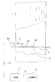
図1は、流動床オレフィン重合反応容器及びその周辺配管系統を示す図である。混合相容器としての流動床オレフィン重合反応容器1の内部では、気体と粉体の混合相が形成されて流動化しており、この状態で重合反応が進行している。流動床オレフィン重合反応容器1内の圧力は、1〜3MPa程度、温度は70〜100℃程度である。
【0019】
流動床オレフィン重合反応容器1内には、触媒とエチレンガス等のオレフィンガスとが注入口4から供給され、循環ガスブロワ5により、循環ガスがガスライン7を経由して常時循環している。循環ガス経路中にある熱交換器6は、循環ガスの温度調整を行うためのものである。
【0020】
流動床オレフィン重合反応容器1内で重合反応により生成された紛状のポリエチレンやポリプロピレン等の製品は、排出バルブ8、排出ライン9を経て、一次サイロ10に送られて一時的に蓄えられる。製品は、更にロータリバルブ11によって空送ライン13に切り出され、空送ブロワ12の風力により所望の場所に送られる。
【0021】
図2は、流動床オレフィン重合反応容器1の底部分の拡大図であり、内部構造が判るようにその一部を切り欠いてある。流動床オレフィン重合反応容器1の下方部から送り込まれた循環ガスは、分散板2に多数設けられたそれぞれの開口孔21から上方に吹き出し、これにより、流動床オレフィン重合反応容器1内は、気体と粉体の混合相が形成される。そして、その中で重合反応が進行する。
【0022】
その過程において、混合相の状態変化などにより塊状の塊化物20が生成される。この生成プロセスは未だ十分には解明されていない。
生成された塊化物が小さい間においては、塊化物は混合相内部の粒子の流れに伴って浮遊した状態で混合相内部を循環する。塊化物が成長して大きくなると、塊化物はもはや粒子とともに流動化されず混合相内を沈降する。このような塊化物は、一般には分散板の近傍で、滞留するか又は分散板開口孔からの循環ガスにより不規則な運動をすることになる。
【0023】
ここで、本件出願人は、このような大きな塊化物を分散板2上で移動させるために、分散板2の開口孔21からの循環ガスに指向性を持たせ、例えば同一円周方向にそれぞれの開口孔21を向けることにより、分散板上に円周方向のガス及び粒子の流れを発生させる粒子旋回型分散板を開発し、特許出願を行った(特開平6−136013号公報参照)。本実施形態では、分散板2としてこの粒子旋回型分散板を用いている。
【0024】
図3に示すように、この粒子旋回型分散板2は、ガスを吹き出すための開口孔21を容器断面と同心円をなす円周上に配置し、該開口孔21の上に流線型をしたキャップ22を配設したものである。これにより、ガスは粒子旋回型分散板2の開口孔21に沿って水平方向に吹き出される。図3においては、反時計回りのガスの流れが生ずることになる。
従って、上述したような大きな塊化物であっても、そのガスの流れに乗せて粒子旋回型分散板2上を一定の方向(図3では反時計回り)に旋回移動させることができる。なお、この塊化物の混合相内部での挙動は、その大きさだけでなく、操作条件、例えばガス流速等に依存するが、高ガス流速とすればこのような大きな塊化物でも移動させ得る。
【0025】
ところで、流動床オレフィン重合反応容器1の内部には、図2に示すように、オレフィン重合物同士が付着・成長して生成される上記塊化物20を検出する塊化物検出装置を構成する検出棒60及び保護管51が設けられている。以下、この検出棒60及び保護管51の詳細について説明する。
【0026】
図4は検出棒60及び保護管51の内部構造を示す側断面図、図5は図4のA−A線拡大断面図である。
保護管51は、その一端を流動床オレフィン重合反応容器1の周壁に固定し、他端をフリーとした、いわゆる片持ち支持状態で、流動床オレフィン重合反応容器1内に突き出しており、上述した粒子旋回型分散板2から所定の高さ位置に設置される。検出棒60は、このステンレス製の中空円筒状の保護管51内に基本的に納められている。
【0027】
上記保護管51は大径の固定部52(例えば、外径48mm、内径15mm)と小径の突出部53(外径22mm、内径12mm)とから構成されている。検出棒60は、この保護管51内に基本的に納められており、この保護管51の固定部52を流動床オレフィン重合反応容器1の周壁に貫通させた状態で、フランジ54を介して流動床オレフィン重合反応容器1に固定されている。
流動床オレフィン重合反応容器1内には、保護管51の突出部53が突出している。これにより反応容器1内で生成された塊化物20は、旋回流に乗って反応容器1の内部を移動して保護管51に衝突することとなる。この衝突によって保護管51は衝突方向に撓む。
【0028】
上記検出棒60は保護管51のほぼ全長に亘って挿入され、その一部が固定されるもので、その一端(保護管51の突出部53側の端部)は、図4のF1、F2で示す2点で保護管51にネジ止めされ、保護管51に固定されている。また反対側の一端はフリーとされ、検出棒60はいわゆる片持ち支持状態で保護管51に挿入され固定されている。
【0029】
ここで、検出棒60の外径(例えば、10mm)は、保護管51の固定部52の内径及び突出部53の内径よりも小さく形成されているので、検出棒60と保護管51との間には間隙が生ずる。従って、検出棒60は、保護管51の突出部53の移動(撓み)に従って、上記ネジ止め点F1を支点とし、上記間隙内を移動するようになっている。
【0030】
図4及び図5に示すように、上記フリーとされた検出棒60の一端には、2個の円筒状の永久磁石61が互いに直交する方向に取り付けられており、これらの永久磁石61は、保護管51の基部に設けられた部屋55の内部に格納される。
【0031】
また、上記部屋55の下面及び左側面(図5における下、左を指す)には、上記検出棒60の永久磁石61に対応して、磁束検知手段としてのコイル70が設置されている。即ち、コイル70の軸と上記円筒状永久磁石61の軸とがほぼ一致するようにコイル70が設置される。また、本実施形態では、通常の状態において永久磁石61の先端の一部がコイル70内に挿入されるように配置されている。
【0032】
上述のように塊化物20が保護管51に衝突すると、該保護管51及びその保護管51に固定された検出棒60が衝突方向に撓み、検出棒60が上記間隙内を移動する。上記検出棒60に取り付けられた永久磁石61もこれに伴って移動する。
そして、この永久磁石61の移動によって、対応するコイル70内の磁束が変化する。この磁束の変化を磁束検知手段としてのコイル70によって計測することで、容器内の塊化物20の存在及び大きさを知ることができる。
【0033】
この各磁束検知手段(コイル70)からの出力信号はケーブル16から変換器17に入力され、ここで、例えば、4〜20mAの電流信号に変換された後、ケーブル18を介して記録警報部19に伝送されてモニタリングされる。
なお、上述のように、2組の永久磁石61及びコイル70は、互いに直交するように設けられているので、保護管51にいずれかの方向から塊化物20が衝突しても、いずれかのコイル70によって磁束の変化を計測できるようになっている。
【0034】
より詳細に説明すると、コイル70内の磁束が変化すると、以下に示す誘導起電力eが発生する。
e=−N×dΦ/dt=NBlv
ここに、N:コイル70の巻数、dΦ/dt:単位時間あたりの磁束の変化、B:コイル70の磁束密度、l:コイル70のエレメントの長さ、v:永久磁石の移動速度で表される。
【0035】
つまり、塊化物20の衝突により保護管51及びその保護管51に固定された検出棒60が撓むと、検出棒60に取り付けられた永久磁石61が移動し、コイル70には永久磁石61の移動速度に比例した誘導起電力が生じる。従って、コイル70の電圧の変化を計測することにより、塊化物20の生成状態を知ることができる。
【0036】
このように、検出棒60に取り付けられた永久磁石61が移動することによって生じる磁束の変化に基づいて、流動床オレフィン重合反応容器1内の塊化物20の生成状態を検出することができ、コイル70の電圧の変化量とこの周期から塊化物20の保護管51への衝突頻度及びその大きさを特定することができる。
【0037】
ここで、この誘電起電力は永久磁石61の移動速度の比例値である。従って、比較的小さな塊化物の衝突により永久磁石61の移動量が微少であったとしても、検出棒の先端が移動し、これにより磁石が移動すると誘導起電力が生じ、これを計測することができる。即ち、小さな塊化物20の衝突であっても検出することができ、流動床オレフィン重合反応容器1内の塊化物20の検出感度を高めることができる。本実施形態では、500g以下の塊化物20であっても検出することができるようになった。
【0038】
なお、上記検出棒60は、流動床オレフィン重合反応容器1の側面に取り付けられており、その粒子旋回型分散板2からの高さh(図2参照)、即ち、所定の高さは、排出バルブ8から塊化物20を抜き出すことができる大きさの塊化物20を検出することが可能な高さであればよく、例えば、5〜15cmとされる。
【0039】
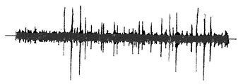
図6は、上記構成の検出棒60を実際に流動床オレフィン重合反応容器1内に配置し、反応容器1内に生成された塊化物20の検出を行った時の実験結果を示すものである。横軸が時間、縦軸が電圧の変化量、即ち磁束の変化量を示している。正常な状態においては、保護管51に流動床オレフィン重合反応容器1内の旋回流によりある程度の負荷がかかっているが、同図において電圧の変化量が安定している部分はこの正常な状態を示している。一方、電圧の変化量が突出している部分は塊化物20が保護管51に衝突したことを示している。
【0040】
なお、上述した粒子旋回型分散板を使用した場合でも、粒子又は塊化物は厳密に水平方向ばかりではなく、垂直方向にも移動するものと考えられるが、検出棒60の垂直方向についても磁束検知手段60が設けられているので、かかる垂直方向に移動する粒子又は塊化物をも捕捉することができる。
【0041】
また、ガス又は粒子の流れに沿って移動してきた塊化物が保護管51に引っかかり、そのまま滞留する場合があるので、上記保護管51をその挿入角がガス及び粒子の流れに対して20度から70度になるように傾斜させて配置することとすれば、混合相容器内で生成された塊化物が保護管51に引っかかることを少なくすることができる。これにより、更に高感度かつ高精度の検出を行うことができる。
【0042】
ここで、本発明の他の態様である検出棒60の側断面図を図7に示す。
本態様においては上述した保護管は設けられていない。検出棒60の一部62を流動床オレフィン重合反応容器1の周壁に前記混合相容器に固定し、一端をフリーとしており、検出棒60は流動床オレフィン重合反応容器1内に露出している。また、磁束検知手段としてのコイル70は流動床オレフィン重合反応容器1に対して固定的に設けられている。
これにより上記実施例と同様に上記検出棒60の一端に取り付けられた永久磁石61の移動による磁束の変化を計測することができ、従って、図7の構成によっても、容器内の塊化物20の存在及び大きさを知ることができる。
【0043】
【発明の効果】
上述したように本発明は、塊化物が保護管及びその保護管に固定された検出棒に衝突することにより、該検出棒に取り付けられた磁石が均一な磁束の中を移動し、この磁石の移動による上記磁束の変化に基づいて塊化物の生成状態を検出するものであるため、塊化物の衝突に伴う永久磁石の移動速度の比例値を基準に塊化物の生成状態を検出するため、小さな塊化物の衝突であっても容易に検出することができる。従って、混合相容器内の塊化物の検出感度を高めることができる。
【0044】
更に、混合相容器の底部に粒子旋回型分散板を配置して循環ガスを水平方向に吹き出し、検出棒を粒子旋回型分散板の上方所定の高さの位置に設置したことにより、混合相容器内部のガス又は粒子の流れをコントロールすることができ、検出棒に対して塊化物を有効に衝突させることができる。従って、より高感度の検出を行うことができる。
【図面の簡単な説明】
【図1】流動床オレフィン重合反応容器及びその周辺配管系統を示す系統図である。
【図2】本発明の一実施例が適用される流動床オレフィン重合反応容器の部分拡大図である。
【図3】図2に示す粒子旋回型分散板の平面図である。
【図4】本発明の一実施例における検出棒及び保護管の側断面図である。
【図5】図4のA−A線拡大断面図である。
【図6】検出棒を設置してコイルの電圧を測定した時の実験結果を示すグラフである。
【図7】本発明の他の実施例における検出棒の側断面図である。
【符号の説明】
1 流動床オレフィン重合反応容器(混合相容器)
2 (粒子旋回型)分散板
20 塊化物
21 開口孔
22 キャップ
51 保護管
60 検出棒
61 永久磁石
70 コイル(磁束検知手段)
F1 ネジ止め点(支点)[0001]
BACKGROUND OF THE INVENTION
The present invention relates to a method for detecting an agglomerate produced in a mixed phase vessel such as a fluidized bed olefin polymerization reaction vessel, an apparatus for detecting the agglomerate, a fluidized bed olefin polymerization reaction device equipped with the device, and an olefin polymerization method. It is about.
[0002]
[Prior art]
As a method for detecting an agglomerate produced in a mixed phase vessel such as a fluidized bed olefin polymerization reaction vessel, a method utilizing radiation is known (for example, see Japanese Examined Patent Publication No. 62-28961). This is because the radiation source is arranged at the center of the container, and a plurality of radiation detectors are arranged on the outer periphery of the container to detect the density change of the mixed phase existing between the radioactive source and the detector, and to agglomerate It is to know the existence and the size of.
[0003]
As another method, there is a method in which capacitance detection means is arranged on the inner wall of the mixed phase container (Japanese Patent Laid-Open No. 4-361150). This is because the density of the agglomerate is larger than the density of the mixed phase, and when the gel-like agglomerate is generated and adhered to the inner wall surface in the mixed phase container, the capacitance of the inner wall surface changes. It is intended to detect the production state of the agglomerate by measuring.
[0004]
As another method, there is a method in which a detection rod provided with strain detection means is arranged in a mixed phase container (Japanese Patent Laid-Open No. 10-36447). In this case, the presence and the size of the agglomerate are known from the amount of distortion generated when the produced agglomerate collides with the detection rod. That is, by arranging a detection rod inside the mixed phase container and providing a strain gauge on the detection rod, the strain of the detection rod due to the collision of the agglomerates is measured, and the presence and size of the agglomerates are known. It is a thing.
[0005]
[Problems to be solved by the invention]
However, in the above-described method for detecting agglomerates using radiation, for example, in a fluidized bed olefin polymerization reaction vessel, the vessel generally has a huge substantially cylindrical shape with a diameter of several meters and a height of several tens of meters. When a blockage occurs in the interior or when a periodic inspection is performed, it is necessary for an operator to enter the container and remove the blockage or perform an inspection operation. Therefore, when a radiation source is arranged in the container, it is necessary to give sufficient consideration to ensuring the safety of the work in the container.
[0006]
Further, in the detection method using the capacitance detection means, there is no problem regarding ensuring the safety, and the agglomerated material moving in the container is suitable for detection of the agglomerated material adhering to the inner peripheral wall of the mixed phase container. It is not enough for detection. Furthermore, when the generated agglomerated material is still small, the density difference between the normal olefin polymer and the agglomerated material is small, and detection of the agglomerated material adhering to the inner wall surface of the container is not sufficient.
[0007]
On the other hand, the detection method using the strain detection means does not have these problems, but the agglomerate must collide with the detection rod effectively. Since the generated agglomerated material moves along the flow of gas or particles inside the mixed phase, if the flow of the gas or particles inside the mixed phase is not known in advance, it is effective for the detection rod due to the agglomeration collision. There is a case where the detection sensitivity is remarkably lowered without being given an impact.
[0008]
In addition, since a strain gauge is used, the measured value is a proportional value of the strain amount of the detection rod. Therefore, when the agglomerated material that collides is small, the measured value does not change slightly and it is difficult to detect this. That is, the detection sensitivity of the agglomerates is not sufficient, and it is generally difficult to detect agglomerates of 500 g or less.
Furthermore, when the agglomerate is large, the agglomerate may stay in the detection rod part. However, when the strain gauge is used, if the agglomerate stays in the detection bar part, the distorted state continues and the detection rod The signal continues to be output from and the generation of new agglomerates and changes in the mixed phase cannot be detected.
[0009]
The present invention has been made in view of the problems of the prior art as described above, and is an agglomerated substance detection method and an agglomerated substance that are highly safe, capable of detecting even small agglomerated substances, and capable of performing highly sensitive and highly accurate detection. It is an object of the present invention to provide a compound detection apparatus, a fluidized bed olefin polymerization reaction apparatus equipped with the apparatus, and an olefin polymerization method.
[0010]
[Means for Solving the Problems]
In order to solve such a problem in the prior art, the present invention according to claim 1 is configured to detect an agglomerate in a mixed phase container in which a mixed phase is formed by gas and powder and fluidized. In the detection method, a protective tube with one end fixed to the mixed phase vessel and the other end free is disposed inside the mixed phase vessel, and a detection rod is inserted into the free end of the protective tube. The magnet is attached to the other end of the detection rod, the magnet is placed in a uniform magnetic flux, and the magnet is moved using one point of the detection rod as a fulcrum to move the magnet. The change of the magnetic flux accompanying it is measured, and presence of a lump-like agglomerate is detected. Thereby, the production | generation state of an agglomerate is detectable on the basis of the proportional value of the moving speed of the permanent magnet accompanying the collision of an agglomerate.
[0011]
In another embodiment of the present invention, a detection rod having a part fixed to the mixed phase vessel and free at one end is disposed inside the mixed phase vessel, and a magnet is attached to the other end of the detection rod to be uniform. And the magnet is moved with one point of the detection rod as a fulcrum, and the change of the magnetic flux accompanying the movement of the magnet is measured to detect the presence of a lump-like agglomerate. To do.
[0012]
Furthermore, a particle swirl type dispersion plate is arranged below the inside of the mixed phase container, the circulating gas is blown out horizontally, and the detection rod is installed at a predetermined height above the particle swirl type dispersion plate. It is also a feature. Thereby, the flow of gas or particles inside the mixed phase container can be controlled, and the agglomerate can be effectively collided with the detection rod.
[0013]
An agglomerated substance detection apparatus according to the present invention is an agglomerated substance detection device for detecting agglomerated agglomerated substance in a mixed phase container in which a mixed phase is formed and fluidized with gas and powder, and the mixed phase container A protective tube with one end fixed to the mixed-phase container and the other end free is disposed inside, and a detection rod is inserted into the free end of the protective tube, a part of which is fixed, and the detection A magnet that moves in a uniform magnetic flux with one point of the detection rod as a fulcrum is attached to the other end of the rod, and magnetic flux detection means for detecting a change in the magnetic flux accompanying the movement of the magnet is provided. Is. Thereby, the production | generation state of an agglomerate is detectable on the basis of the proportional value of the moving speed of the permanent magnet accompanying the collision of an agglomerate.
[0014]
In addition, a particle swirl type dispersion plate that blows circulating gas horizontally and circumferentially is disposed at the bottom of the mixed phase container, and the detection rod is installed at a predetermined height above the particle swirl type dispersion plate. It is also a feature. Thereby, the flow of gas or particles inside the mixed phase container can be controlled, and the agglomerate can be effectively collided with the detection rod.
[0015]
The fluidized bed olefin polymerization reaction apparatus according to the present invention is characterized by including the agglomerate detection apparatus described above.
[0016]
The olefin polymerization method according to the present invention is characterized in that the agglomerated material in the mixed phase vessel is detected by the agglomerated material detection method described above, and the agglomerated material is extracted and removed from the mixed phase vessel.
[0017]
DETAILED DESCRIPTION OF THE INVENTION
Hereinafter, an embodiment of the present invention applied to a fluidized bed olefin polymerization reaction vessel as a mixed phase vessel will be described with reference to the drawings.
[0018]
FIG. 1 is a diagram showing a fluidized bed olefin polymerization reaction vessel and its surrounding piping system. Inside the fluidized bed olefin polymerization reaction vessel 1 as a mixed phase vessel, a mixed phase of gas and powder is formed and fluidized, and the polymerization reaction proceeds in this state. The pressure in the fluidized bed olefin polymerization reaction vessel 1 is about 1 to 3 MPa, and the temperature is about 70 to 100 ° C.
[0019]
In the fluidized bed olefin polymerization reaction vessel 1, a catalyst and an olefin gas such as ethylene gas are supplied from an
[0020]
A product such as powdered polyethylene or polypropylene produced by the polymerization reaction in the fluidized bed olefin polymerization reaction vessel 1 is sent to the
[0021]
FIG. 2 is an enlarged view of the bottom portion of the fluidized bed olefin polymerization reaction vessel 1, with a part thereof cut away so that the internal structure can be seen. The circulating gas fed from the lower part of the fluidized bed olefin polymerization reaction vessel 1 is blown upward from the respective opening holes 21 provided in a large number in the dispersion plate 2. And a mixed phase of powder is formed. And polymerization reaction advances in it.
[0022]
In the process, a lump-like agglomerated
While the generated agglomerated material is small, the agglomerated material circulates inside the mixed phase in a floating state with the flow of particles inside the mixed phase. As the agglomerates grow and grow, the agglomerates are no longer fluidized with the particles and settle in the mixed phase. Such agglomerates generally stay in the vicinity of the dispersion plate or move irregularly due to the circulating gas from the openings of the dispersion plate.
[0023]
Here, in order to move such a large agglomerate on the dispersion plate 2, the applicant assigns directivity to the circulating gas from the opening holes 21 of the dispersion plate 2, for example, in the same circumferential direction. A particle swirl type dispersion plate that generates a flow of gas and particles in the circumferential direction on the dispersion plate by directing the
[0024]
As shown in FIG. 3, the particle swirl type dispersion plate 2 has an
Therefore, even a large agglomerate as described above can be swung on the particle swirl type dispersion plate 2 in a certain direction (counterclockwise in FIG. 3) on the gas flow. The behavior of the agglomerate inside the mixed phase depends not only on the size but also on the operating conditions such as the gas flow rate, but even a large agglomerate can be moved at a high gas flow rate.
[0025]
By the way, in the fluidized bed olefin polymerization reaction vessel 1, as shown in FIG. 2, as shown in FIG. 60 and a
[0026]
4 is a side sectional view showing the internal structure of the
One end of the
[0027]
The
A protruding
[0028]
The
[0029]
Here, since the outer diameter (for example, 10 mm) of the
[0030]
As shown in FIGS. 4 and 5, two cylindrical
[0031]
In addition, on the lower surface and the left side surface of the chamber 55 (pointing to the lower side and the left side in FIG. 5), coils 70 serving as magnetic flux detection means are installed corresponding to the
[0032]
When the agglomerated
The movement of the
[0033]
The output signal from each magnetic flux detection means (coil 70) is input from the
As described above, the two
[0034]
If it demonstrates in detail, if the magnetic flux in the
e = −N × dΦ / dt = NBlv
Here, N: number of turns of
[0035]
That is, when the
[0036]
Thus, based on the change in the magnetic flux generated by the movement of the
[0037]
Here, this dielectric electromotive force is a proportional value of the moving speed of the
[0038]
The
[0039]
FIG. 6 shows an experimental result when the
[0040]
Even when the particle swirl type dispersion plate described above is used, it is considered that particles or agglomerates move not only in the horizontal direction but also in the vertical direction. Due to the provision of
[0041]
In addition, since the agglomerated material that has moved along the flow of the gas or particles may be caught by the
[0042]
Here, FIG. 7 shows a side sectional view of a
In this embodiment, the protective tube described above is not provided. A
As a result, the change in magnetic flux due to the movement of the
[0043]
【The invention's effect】
As described above, according to the present invention, the agglomerated material collides with the protective tube and the detection rod fixed to the protective tube, so that the magnet attached to the detection rod moves in a uniform magnetic flux. Since the agglomerate generation state is detected based on the change in the magnetic flux due to the movement, the agglomerate generation state is detected based on the proportional value of the moving speed of the permanent magnet accompanying the agglomerate collision. Even an agglomeration collision can be easily detected. Therefore, the detection sensitivity of the agglomerates in the mixed phase container can be increased.
[0044]
Further, the particle swirl type dispersion plate is disposed at the bottom of the mixed phase container, the circulating gas is blown out in the horizontal direction, and the detection rod is installed at a predetermined height above the particle swirl type dispersion plate. The flow of gas or particles inside can be controlled, and the agglomerate can be effectively collided with the detection rod. Therefore, detection with higher sensitivity can be performed.
[Brief description of the drawings]
FIG. 1 is a system diagram showing a fluidized bed olefin polymerization reaction vessel and its surrounding piping system.
FIG. 2 is a partially enlarged view of a fluidized bed olefin polymerization reaction vessel to which one embodiment of the present invention is applied.
3 is a plan view of the particle swirl type dispersion plate shown in FIG. 2. FIG.
FIG. 4 is a side sectional view of a detection rod and a protective tube in one embodiment of the present invention.
5 is an enlarged sectional view taken along line AA in FIG.
FIG. 6 is a graph showing experimental results when a detection rod is installed and the coil voltage is measured.
FIG. 7 is a side sectional view of a detection rod in another embodiment of the present invention.
[Explanation of symbols]
1 Fluidized bed olefin polymerization reaction vessel (mixed phase vessel)
2 (particle swirl type)
F1 Screw fixing point (fulcrum)
Claims (8)
前記混合相容器の内部に、一端を前記混合相容器に固定し他端をフリーとした保護管を配置するとともに、前記保護管のフリーとした一端に検出棒を挿入してその一部を固定し、
前記検出棒の他端に磁石を取り付け該磁石を均一な磁束の中に配置するとともに、該磁石を前記検出棒の一点を支点として移動させ、
前記磁石の移動に伴う前記磁束の変化を計測して塊状の塊化物の存在を検知することを特徴とする塊化物検出方法。An agglomerate detection method for detecting an agglomerate in a mixed phase container in which a mixed phase is formed and fluidized with gas and powder,
A protective tube with one end fixed to the mixed phase vessel and the other end free is disposed inside the mixed phase vessel, and a detection rod is inserted into the free end of the protective tube and a part thereof is fixed. And
A magnet is attached to the other end of the detection rod, the magnet is placed in a uniform magnetic flux, and the magnet is moved using one point of the detection rod as a fulcrum,
A method for detecting an agglomerate, comprising: measuring a change in the magnetic flux accompanying the movement of the magnet to detect the presence of an agglomerate.
前記混合相容器の内部に、一部を前記混合相容器に固定し一端をフリーとした検出棒を配置し、
前記検出棒の他端に磁石を取り付け該磁石を均一な磁束の中に配置するとともに、該磁石を前記検出棒の一点を支点として移動させ、
前記磁石の移動に伴う前記磁束の変化を計測して塊状の塊化物の存在を検知することを特徴とする塊化物検出方法。An agglomerate detection method for detecting an agglomerate in a mixed phase container in which a mixed phase is formed and fluidized with gas and powder,
Inside the mixed phase container, a detection rod having a part fixed to the mixed phase container and free at one end is arranged,
A magnet is attached to the other end of the detection rod, the magnet is placed in a uniform magnetic flux, and the magnet is moved using one point of the detection rod as a fulcrum,
A method for detecting an agglomerate, comprising: measuring a change in the magnetic flux accompanying the movement of the magnet to detect the presence of an agglomerate.
前記混合相容器の内部に、一端を前記混合相容器に固定し他端をフリーとした保護管を配置するとともに、前記保護管のフリーとした一端に検出棒を挿入してその一部を固定し、
前記検出棒の他端には、前記検出棒の一点を支点として均一な磁束の中を移動する磁石を取付け、
前記磁石の移動に伴う前記磁束の変化を検知する磁束検知手段を設けたことを特徴とする塊化物検出装置。An agglomerated substance detection device for detecting an agglomerated substance in a mixed phase container in which a mixed phase is formed and fluidized with gas and powder,
A protective tube with one end fixed to the mixed phase vessel and the other end free is disposed inside the mixed phase vessel, and a detection rod is inserted into the free end of the protective tube and a part thereof is fixed. And
At the other end of the detection rod, a magnet that moves in a uniform magnetic flux with one point of the detection rod as a fulcrum is attached,
An agglomerated substance detection apparatus comprising a magnetic flux detection means for detecting a change in the magnetic flux accompanying the movement of the magnet.
前記混合相容器の内部に、一部を前記混合相容器に固定し一端をフリーとした検出棒を配置し、
前記検出棒の他端には、前記検出棒の一点を支点として均一な磁束の中を移動する磁石を取付け、
前記磁石の移動に伴う前記磁束の変化を検知する磁束検知手段を設けたことを特徴とする塊化物検出装置。An agglomerated substance detection device for detecting an agglomerated substance in a mixed phase container in which a mixed phase is formed and fluidized with gas and powder,
Inside the mixed phase container, a detection rod having a part fixed to the mixed phase container and free at one end is arranged,
At the other end of the detection rod, a magnet that moves in a uniform magnetic flux with one point of the detection rod as a fulcrum is attached,
An agglomerated substance detection apparatus comprising a magnetic flux detection means for detecting a change in the magnetic flux accompanying the movement of the magnet.
Priority Applications (1)
| Application Number | Priority Date | Filing Date | Title |
|---|---|---|---|
| JP2000367145A JP4627112B2 (en) | 1999-12-10 | 2000-12-01 | Agglomerated substance detection method, agglomerated substance detection apparatus, fluidized bed olefin polymerization reaction apparatus equipped with the apparatus, and olefin polymerization method |
Applications Claiming Priority (3)
| Application Number | Priority Date | Filing Date | Title |
|---|---|---|---|
| JP35184499 | 1999-12-10 | ||
| JP11-351844 | 1999-12-10 | ||
| JP2000367145A JP4627112B2 (en) | 1999-12-10 | 2000-12-01 | Agglomerated substance detection method, agglomerated substance detection apparatus, fluidized bed olefin polymerization reaction apparatus equipped with the apparatus, and olefin polymerization method |
Publications (2)
| Publication Number | Publication Date |
|---|---|
| JP2001228119A JP2001228119A (en) | 2001-08-24 |
| JP4627112B2 true JP4627112B2 (en) | 2011-02-09 |
Family
ID=26579497
Family Applications (1)
| Application Number | Title | Priority Date | Filing Date |
|---|---|---|---|
| JP2000367145A Expired - Fee Related JP4627112B2 (en) | 1999-12-10 | 2000-12-01 | Agglomerated substance detection method, agglomerated substance detection apparatus, fluidized bed olefin polymerization reaction apparatus equipped with the apparatus, and olefin polymerization method |
Country Status (1)
| Country | Link |
|---|---|
| JP (1) | JP4627112B2 (en) |
Citations (3)
| Publication number | Priority date | Publication date | Assignee | Title |
|---|---|---|---|---|
| JPH06109403A (en) * | 1992-01-14 | 1994-04-19 | Metro-Le:Kk | Lever-type detector |
| JPH06136013A (en) * | 1992-10-26 | 1994-05-17 | Sumitomo Chem Co Ltd | Gas diffusion plate of fluidized bed type reactor |
| JPH1036447A (en) * | 1996-07-23 | 1998-02-10 | Sumitomo Chem Co Ltd | Method and apparatus for detecting lump and polymerizer equipped with this apparatus |
Family Cites Families (3)
| Publication number | Priority date | Publication date | Assignee | Title |
|---|---|---|---|---|
| JPH0328357Y2 (en) * | 1984-12-27 | 1991-06-18 | ||
| JPS62115132U (en) * | 1985-12-20 | 1987-07-22 | ||
| JPH10319035A (en) * | 1997-03-19 | 1998-12-04 | Yaskawa Electric Corp | Acceleration sensor |
-
2000
- 2000-12-01 JP JP2000367145A patent/JP4627112B2/en not_active Expired - Fee Related
Patent Citations (3)
| Publication number | Priority date | Publication date | Assignee | Title |
|---|---|---|---|---|
| JPH06109403A (en) * | 1992-01-14 | 1994-04-19 | Metro-Le:Kk | Lever-type detector |
| JPH06136013A (en) * | 1992-10-26 | 1994-05-17 | Sumitomo Chem Co Ltd | Gas diffusion plate of fluidized bed type reactor |
| JPH1036447A (en) * | 1996-07-23 | 1998-02-10 | Sumitomo Chem Co Ltd | Method and apparatus for detecting lump and polymerizer equipped with this apparatus |
Also Published As
| Publication number | Publication date |
|---|---|
| JP2001228119A (en) | 2001-08-24 |
Similar Documents
| Publication | Publication Date | Title |
|---|---|---|
| US5572121A (en) | Metal detector including a metal screening for producing a secondary magnetic field to reduce the metal free zone | |
| WO2001014911A1 (en) | Real time monitoring of electron beam radiation dose | |
| JPH03111791A (en) | Metal detector and tester therefor | |
| US6521723B2 (en) | Method and apparatus for detecting agglomerates | |
| JP4627112B2 (en) | Agglomerated substance detection method, agglomerated substance detection apparatus, fluidized bed olefin polymerization reaction apparatus equipped with the apparatus, and olefin polymerization method | |
| WO2008028991A1 (en) | An arrangement and method for monitoring the condition of a bed of a fluidized bed reactor | |
| JP3657485B2 (en) | Agglomerated substance detection method, agglomerated substance detection apparatus, fluidized bed olefin polymerization reaction apparatus equipped with the apparatus, and olefin polymerization method | |
| AU2013257764B2 (en) | Ore analysis system | |
| EP1012628B1 (en) | Monitoring and/or detecting alpha-radiation sources | |
| US4794256A (en) | Fast neutron process measurement system | |
| US6905654B2 (en) | Method and apparatus for reducing static charges during polymerization of olefin polymers | |
| KR100686446B1 (en) | Method of measuring neutron for detecting the distribution of nuclear material and device for the same | |
| JP3313030B2 (en) | Agglomerate detection method and device, and polymerization tank equipped with the device | |
| CN116313183A (en) | Ball bed type high temperature gas cooled reactor fuel element counting device and method | |
| CN103257090A (en) | Method for detecting caking condition in stirred bed reactor | |
| KR840001664B1 (en) | Method for detecting solidification in a mixed phase container | |
| JP5317401B2 (en) | Emission clearance online monitoring system | |
| US20220397539A1 (en) | System and methods of charged particle detectors for blast furnace imaging | |
| Deboy et al. | Acoustic Measurements in the Collimation Region of the LHC | |
| Van Oost et al. | Joint experiments on small tokamaks | |
| Kovařík et al. | Measurement of safety factor using Hall probes on CASTOR tokamak | |
| Boshakova et al. | Measurement of safety factor using Hall probes on CASTOR tokamak | |
| LHCb | LHCb: Mechanical design and vacuum system of the LHCb VErtex LOcator | |
| Ogiwara et al. | The fast pressure monitoring system on JT-60 | |
| Menon et al. | Detection of low-velocity microparticles occurring in an ultra-high-vacuum test chamber |
Legal Events
| Date | Code | Title | Description |
|---|---|---|---|
| A621 | Written request for application examination |
Free format text: JAPANESE INTERMEDIATE CODE: A621 Effective date: 20070528 |
|
| A977 | Report on retrieval |
Free format text: JAPANESE INTERMEDIATE CODE: A971007 Effective date: 20090701 |
|
| A131 | Notification of reasons for refusal |
Free format text: JAPANESE INTERMEDIATE CODE: A131 Effective date: 20100706 |
|
| TRDD | Decision of grant or rejection written | ||
| A01 | Written decision to grant a patent or to grant a registration (utility model) |
Free format text: JAPANESE INTERMEDIATE CODE: A01 Effective date: 20101102 |
|
| A01 | Written decision to grant a patent or to grant a registration (utility model) |
Free format text: JAPANESE INTERMEDIATE CODE: A01 |
|
| A61 | First payment of annual fees (during grant procedure) |
Free format text: JAPANESE INTERMEDIATE CODE: A61 Effective date: 20101104 |
|
| FPAY | Renewal fee payment (event date is renewal date of database) |
Free format text: PAYMENT UNTIL: 20131119 Year of fee payment: 3 |
|
| R150 | Certificate of patent or registration of utility model |
Ref document number: 4627112 Country of ref document: JP Free format text: JAPANESE INTERMEDIATE CODE: R150 Free format text: JAPANESE INTERMEDIATE CODE: R150 |
|
| LAPS | Cancellation because of no payment of annual fees |