JP4626865B2 - Long gun for high temperature liquid or melt - Google Patents
Long gun for high temperature liquid or melt Download PDFInfo
- Publication number
- JP4626865B2 JP4626865B2 JP2001241417A JP2001241417A JP4626865B2 JP 4626865 B2 JP4626865 B2 JP 4626865B2 JP 2001241417 A JP2001241417 A JP 2001241417A JP 2001241417 A JP2001241417 A JP 2001241417A JP 4626865 B2 JP4626865 B2 JP 4626865B2
- Authority
- JP
- Japan
- Prior art keywords
- block
- melt
- gun
- support
- longitudinal direction
- Prior art date
- Legal status (The legal status is an assumption and is not a legal conclusion. Google has not performed a legal analysis and makes no representation as to the accuracy of the status listed.)
- Expired - Lifetime
Links
Images


Landscapes
- Coating Apparatus (AREA)
- Nozzles (AREA)
Description
【0001】
【発明の属する技術分野】
本発明は、例えばエアフィルタ等のフィルタの幅の広い濾材等、幅広の被塗物に高温溶融状態のホットメルト等の高温の液体又は溶融体を塗布するための長尺ガンに係り、特に、熱膨張等による熱変形に対して小型化、軽重量化し得るなどした高温の液体又は溶融体用の長尺ガン関する。
【0002】
【従来の技術】
従来から、エアフィルタ等のフィルタの多数のプリーツを備える濾材を形成する場合において、予め折り目線に沿ってひだ折り加工した後に平面状に引き伸ばした濾材の表面に液体又は溶融体としての高温のホットメルトを線状或いはビード状に断続的、或いは、連続的に塗布し、その後、該濾材を該折り目線に沿って折り曲げてプリーツ加工することにより、該濾材のプリーツのピッチ(間隔)を固定する方法がとられている。このような目的で濾材表面にホットメルトを塗布する場合に、該濾材の幅の広い幅広濾材にホットメルトを塗布する場合、或いは、幅の狭い濾材に対して塗布能率を向上させるため濾材を複数枚、横に並べて一度に塗布する場合に、ホットメルト吐出用ノズルを備えたガンモジュールを横方向に多数併置した長尺ガンが用いられている。
【0003】
このような長尺ガンは、内部の長手方向にホットメルト供給通路を貫通して形成した1本の長手方向に延びる金属製の長尺状のブロックに、該ブロックの該供給通路と連通した供給通路を通して供給されるホットメルトをビード状に吐出させるためのノズルを備えたガンモジュールが該ブロックの長手方向に所定の間隔をおいて多数併置されて取付けられることにより、構成されている。
【0004】
【発明が解決しようとする課題】
該多数のガンモジュールを取付けるための該ブロックは、該ブロックの長手方向に延びて内挿されたカートリッジヒータ等の加熱器による加熱作用を受けて内部のホットメルト供給通路を温度が例えば通常180℃、最高250℃の高温の溶融状態のホットメルトが流通される。そして、このような高温のホットメルトの流通による熱膨張によりブロック自体が変形することを極力阻止し、該ブロックに取付けられるガンモジュールの先端のノズルの吐出口位置が被塗物である濾材に対して狂わないようにするために、該ブロックに剛性を持たせることが行われている。
【0005】
しかしながら、特に該ブロックの幅(ブロックの長手方向の長さ)が、例えば500mmを超えるような長尺ガンでは、ブロックにそのように熱変形に対して剛性を保持せしめるためには、ブロック自体の幅が大きく(長く)なるに応じて、その高さ方向、或いは、奥行き方向、の長さをも長くしてやる必要があり、そのために該幅と高さと奥行きの長さを掛け合わせた該ブロックの容積は激増する。極論すれば、例えば、ブロックの幅が既存ガンの2倍の長尺ガンが必要である場合、熱変形に耐える剛性を維持するために、その高さ、その長さともに2倍の大きさにせねばならないとすれば、体積は8倍にもなってしまう。このようにブロックの幅が長くなれば、それに応じて、容積は大きいものとなり、そのため重量も過大になる。従って、ガン全体が極めて大型で大重量となってしまう。さらに、そのガンを固定支持するための支持体も剛性も大きくする必要があり、それにより大型化する必要があり、従って、ガン設備全体が極めて大型で重量大になってしまう。そして、そのために製造コストも必要以上に高くなる。
【0006】
また、1本ものの長いブロックを製作する場合においては、該ブロックに、長手方向に延びる、長さが長い主ホットメルト供給通路、及び、カートリッジヒータ等の加熱ヒータの挿入設置のためのヒータ挿入穴を形成させる必要があり、さらに該ブロックには該ブロックに長手方向に併置して取付けられる多数のガンモジュールの取付位置に対応した位置に該主ホットメルト供給通路から分岐し該各々のガンモジュールに連通させるための多数のホットメルト供給通路、さらに別に該ガンモジュールのホットメルト供給弁を作動させるための圧縮空気供給用の通路を穿孔加工せねばならず、穿孔加工が極めて困難であると共に穿孔作業能率が極めて悪く、製作が容易ではない。そして、そのために製造コストも高くなるという問題もあった。
【0007】
本発明は、以上のような1本の幅の広いブロックで構成された長尺ガンの欠点を解消するためになされたものであり、長尺ガンであっても熱膨張等による熱変形による剛性増加の必要性を排除し、小型化、軽重量化し得、また製作容易化し得、さらに製造コストを低減し得るなどした高温の液体又は溶融体用の長尺ガンを提供することを目的とする。
【0008】
【課題を解決するための手段】
上記の目的を達成するために、本発明は次のような構成とした。
(1)内部に高温の液体又は溶融体の供給通路を有し長手方向に延びた長尺のブロックに、該ブロックの該供給通路と連通した液体又は溶融体の供給通路を通して供給される該液体又は溶融体を吐出させるためのノズルを備えたガンモジュールを該ブロックの長手方向に多数併置して取付けた高温の液体又は溶融体用長尺ガンであって、該長尺ガンの該ブロックをその長手方向に複数に分割し、該分割された各々のブロックを連結部材で連結すると共に、該各々のブロックの液体または溶融体の供給通路を相互に管継ぎ手で連通させることにより、全体を一体に連結して、高温の液体又は溶融体用の長尺ガンを構成とした。
【0009】
(2)上記(1)の高温の液体又は溶融体用の長尺ガンにおいて、上記管継ぎ手は、各分割ブロックの分割端面に形成された液体又は溶融体の供給通路の端部に連通して形成された取付部に対して、嵌合され、かつ、埋設されて取付けられた構成にした。
【0010】
(3)上記(1)又は(2)の高温の液体又は溶融体用の長尺ガンにおいて、上記各々の分割ブロックは、加熱器が内装されると共に、各々の接合端面が所定の隙間を空けて連結される構成とした。
【0011】
(4)上記(1)又は(2)又は(3)の高温の液体又は溶融体用の長尺ガンにおいて、各々の分割ブロックの連結部付近、及び、該ブロックの長手方向の適宜な個所のブロックと支持体との間に、ブロックを支持体に対してノズルの液体又は溶融体の吐出方向と同一方向に引き寄せ、及び、引き離すための一対の引き寄せ手段、及び、引き離し手段を、複数対、取付け、多数のガンモジュールのノズル先端の被塗物に対する位置を調整又は補正可能な構成とした。
【0012】
(5)上記(4)の高温の液体又は溶融体用の長尺ガンにおいて、前記ブロックとの間に取付けられる一対の引き寄せ手段、及び、引き離し手段の複数対はそれぞれ個別の第1支持体に取付けられ、該それぞれの第1支持体は第2支持体に該ブロックの長手方向と同一方向に摺動可能に取付けられた構成とした。
【0013】
【作用】
上記(1)の構成では、長尺ガンのガンモジュールを保持するブロックが分割されて幅が狭く(短く)形成されることにより、該各々のブロックは内部の供給通路に高温の液体又は溶融体が流されても、各々の分割ブロックは熱変形に対する剛性を維持するために、該幅の長さに応じて、該幅と交差する方向(奥行き)の長さ、高さ方向の長さをも大きくする必要がなくされ、従って、容積を大きくする必要が排除される。このために、全体幅の大きい長尺ガンであっても、大型化せず、重量大とならず、全体的に小型化、軽量化される。そして、製造コストも安価にされる。そして、1本の長いブロックを製作する場合に比べて、各分割ブロックの液体又は溶融体の供給通路等の穿孔加工が容易で製作し易くなり、加工能率も向上する。そして、この点からも製造コストが低減される。
【0014】
上記(2)の構成では、管継ぎ手がその取付部に嵌合されることによって、管継ぎ手は、分割ブロックを端面連結部において相互の位置決め作用をすると共に、ブロック同士の連結補助部材として作用する。これにより、分割ブロックでなる長尺ガンの組立が容易化される共に、本来の連結部材による連結作用と相俟って、全体的に、より強固に連結、結合される。
【0015】
上記(3)の構成では、各々の分割されたブロックにカートリッジヒータ等の加熱器が内装され、かつ、ブロック同士はその連結部端面が所定の隙間を空けられて連結されることにより、各ブロックの加熱器で加熱された熱が他のブロックに伝達されない。従って、ブロック、即ち、ホットメルト等の液体又は溶融体の温度調整がブロック毎で独立して行われ、連結したブロック全体の温度調整が確実容易に行われる。これにより、該連結したブロック全体に亘って液体又は溶融体の粘度を均等にすることが可能にされ、多数のノズルから被塗物へ均一量の塗布が行われる。
【0016】
上記(4)の構成では、各ブロックの連結部付近、及び、該ブロックの長手方向の適宜の個所のブロックと支持体との間に、ノズルの液体又は溶融体の吐出方向と同一方向にブロックを支持体に対して引き寄せ、及び、引き離すための一対の引き寄せ手段、及び、引き離し手段を複数対、取付けたことにより、両者の間の取付距離が容易に調整可能にされる。従って、たとえ、ブロック側、及び又は、その支持体側が、ブロックが高温にされることによるブロックの熱膨張、ブロックの長手方向の部位による強度や熱負荷の不均衡、支持体に作用する負荷荷重の部位による不均衡、或いは、ブロックと支持体の組み付け強度や組み付け誤差等、に起因して、変形、変位をし、多数併置して設置された各々のガンモジュールのノズルの先端の吐出口の位置が被塗物に対して不均等な距離になったとしても、その不均等個所に対応する個所の引き寄せ手段、及び、引き離し手段によってブロックと支持体との間の距離を調整することにより、ノズル先端の吐出口と被塗物の距離が均等になるように容易に補正、調整が行われる。この場合、一対の引き寄せ手段、及び、引き離し手段が複数対、設けられているため、調整(補正)自由度が高められる。
【0017】
上記(5)の構成では、上記(4)の構成の作用に加えて、ブロックが高温になることによる熱膨張によりもたらされる長手方向への変位(伸び)が、第1支持体が第2支持体を摺動することによって吸収され(逃がされ)、ブロックと支持体との間でブロックの長手方向への熱応力による抵抗力が全く発生しない。従って、ブロック引いては支持体の変形がより少なくされ、ブロックの長手方向に多数併置して設置された各々のガンモジュールのノズル先端の吐出口と被塗物との間の距離の狂いがより少ないものとされる。
【0018】
【発明の実施の形態】
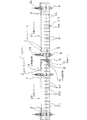
次に、図面に基づいて本発明の実施の形態を説明する。図面はいずれも本発明の実施形態を示すものであり、図1は長尺ガンの正面図、図2は図1の平面図、図3は長尺ガンのブロック連結部の部分拡大図であり右半分は正面図(一部破断図)、左半分は上下の連結プレート及び管継ぎ手の左半分を露出させて示した正面図、図4は図3の平面図(一部破断図)、図5は図3のA〜A線矢視断側面図、図6は図1に示す長尺ガンに支持体を取付けた長尺ガンの正面図、図7は図6の平面図、図8は図6の右側面図、図9は図1に示す長尺ガンに別の異なる支持体を取付けた長尺ガンを示し図1のブロックの正面及び上面をそれぞれ上面及び正面とし、かつ、ブロックの左右を逆様方向に位置させて示した斜視図である。
【0019】
図1〜図5において、長尺ガン1は全体が幅広に、即ち、図1又は図2に示すように左右方向である長手方向の長さを長くして構成されている。しかし、該長尺ガン1を構成する本体であるブロック2は、長手方向の中央部で分割されており、幅の狭い、分割ブロック2a及び分割ブロック2bから構成され、2分割構造とされている。該分割ブロック2a、2bは図5に示すように側面形状が矩形に形成され、その一表面(図1の正面)にはそれぞれ多数のガンモジュール3が長手方向に等間隔で併置されて取付ボルト5がネジ穴6に螺合されることにより取付けられている。なお、図1〜図4において、ガンモジュール3は部分的な個所においてのみ図示し、その他の設置個所は中心線CLで示した。
【0020】
分割ブロック2a、2bには、内部に、液体又は溶融体としてのホットメルト(以下、HMと称することもある)の供給通路8がその長手方向に延在されて穿設されており、さらにHM分岐通路8aがガンモジュール3の取付位置において開口を該ブロックの該モジュール3取付表面に形成させて該HM供給通路8から分岐されて形成されている。
【0021】
該HM供給通路8は、各分割ブロック2a、2bの長手方向の外側端部が図2に示すようにプラグ8bで封止されると共に、各分割ブロック2a、2bの該端部付近の背面に取付けたHMホース接手9と連通されている。一方、各々の分割ブロック2a、2bには、断面略中央部において、その長手方向に延在してヒータ挿入穴10が穿設されており、該ヒータ挿入穴10には図2に示すように細長いカートリッジヒータ11が各分割ブロックの両側から挿入されて中央部でそれぞれの先端が対向された状態で取付けられている。
【0022】
なお、図示していないが、各々のブロックには、温度センサー挿入用穴が形成されて、該穴に温度センサーが挿入設置され、温度検知が可能にされてブロックを一定の温度に維持できるように構成されている。また、分割ブロック2a、2bには該ガンモジュール3の取付位置に対応する位置の頂面(上面)に長手方向に亘って圧縮空気管取付用ねじ穴21が多数、略等間隔で形成されており、各々のネジ穴21には開口を該ブロックのモジュール3の取付表面に形成させた圧縮空気供給通路21aが接続されて形成されている。
【0023】
ガンモジュール3は所謂、ゼロキャビティタイプとされ、ガンモジュール3には、図示していないが、内部に、該HM分岐通路8aと連通し中央部の縦方向に延びて形成されたHM供給通路と、該HM供給通路の上部に形成された空気シリンダの内部に上下方向に摺動自在に設けられた空気圧作動ピストンを備え、下部分が該HM供給通路の内部で上下方向に延び下端に尖ったニードル弁を有したプランジャーとが設けられている。そして、該プランジャーはモジュール3の内部で上端をバネで下方に付勢され、常時はその下端のニードル弁がノズル4のHM排出口の弁座に着座して該ノズルの吐出口を塞ぐ構成とされている。3aはモジュール3の頂部に設けられた該プランジャーの微小のストローク調整を行うためのマイクロアジャストである。
【0024】
該ブロック2a、2bの内部に形成された圧縮空気供給通路21aは該プランジャーの作動ピストンを摺動可能に収容した空気シリンダに連通されている。この構成により、図示していない電磁弁を作動させて図示していない圧縮空気管を介して圧縮空気をブロックの圧縮空気管取付用ねじ穴21及び圧縮空気供給通路21aに供給して該プランジャーの作動ピストンに作用させてやれば、プランジャーが上方へ移動されてニードル弁が弁座から離れ、ブロックのHM供給通路8、分岐通路8a及びモジュール3のHM供給通路を通してホットメルトHMをノズル4の吐出口先端から吐出させて被塗物に塗布することができる。
【0025】
しかして、各々の分割ブロック2a、2bは、それらの内側端部のブロックの連結部Sとなる部分で、連結部材としての上下各2枚の連結板13、14が複数の皿ネジ3aで各ブロック2a、2bにネジ止めされることにより、一体的に連結結合されている。該連結板13、14は図3、図5等に示すようにその表面がブロックの表面と面一になるようにその厚み方向がブロックの内部に沈められて取付けられている。そして、詳細を図3、図4に示すように、各々の分割ブロック2a、2bの連結部Sである内側端部において、各々の分割ブロック2a、2bには、前記ホットメルト供給通路8の端部に両分割ブロック2a、2bの該供給通路8、8を連絡するための管継ぎ手15の取付部としての段付き嵌入穴20が、それぞれ同形状で供給通路8、8と連通された状態で形成されている。
【0026】
管継ぎ手15は中央部に円形の鍔(つば)部16を有し、その両側に袖(そで)部、即ち、スリーブ17を有して形成され、該スリーブ17部にはO(オー)リング取付溝18が形成されている。また、内部にはブロックのHM供給通路8と同径のHM通路15aが貫通して形成されている。該管継ぎ手15の外側形状と該段付き嵌入穴20の内側形状は全体的にほぼ相似形で同寸法に形成されるが、管継ぎ手15と嵌入穴20とは、少なくとも管継ぎ手15の鍔部16と該鍔部16が位置される嵌入穴20の部分が、鍔部16の外周が嵌入穴20の該鍔部16が位置される部分の内周に密着される嵌め合いになるような公差を持った寸法で形成される。また、該鍔部16の厚みと嵌入穴20の該鍔部16が位置する部分の幅(各ブロックの端面からのブロックの長手方向の深さ寸法)は、両方の分割ブロック2a、2bを前記連結板13、14によって連結したときに、該両方のブロックの連結部Sの両端面の隙間Cが所定の隙間、例えば1mm、が付与されるような寸法で形成される。
【0027】
以上のような構成の分割ブロック2a、2b及び管継ぎ手15は、該管継ぎ手15が各分割ブロックの連結部Sの端面の両側の該段付き嵌入穴20に挿入されて嵌合され埋設された状態で上部連結板13及び下部連結板14が両方のブロックに取付けられることにより、一体的に連結されて長尺ブロック2として形成され、全体が幅の広い長尺ガン1として形成される。そして、管継ぎ手15が両ブロック2a、2bへの取付部である段付き嵌入穴20に嵌合されることにより、管継ぎ手15は両ブロック2a、2bを連結部Sの端面において相互の位置決め作用を果すと共にブロック同士の連結補助部材として作用する。このため、長尺ガン1の組立が容易に行えると共に上下の連結板13、14による連結作用と相俟って長尺ガン1が全体としてより強固に連結、結合される。
【0028】
管継ぎ手15と該嵌入穴20との間は管継ぎ手15のOリング取付溝18にOリング19が取付けられてシールされることにより、HM供給通路8を流れるホットメルトの外部への漏洩が防止される。両ブロック2a、2bはこのように一体に連結された状態で管継ぎ手15の鍔部16の作用により、両ブロック2a、2bの連結部Sの端面の間には所定の隙間C、本実施形態では1mmが付与される。これにより、各分割ブロック2a、2bの内部のヒータ挿入穴10に挿入設置されたカートリッジヒータ11で加熱された熱量が他の分割ブロックに伝達されない。
【0029】
従って、ブロック、即ち、高温(通常180℃、最高250℃)のホットメルト、の温度調整を各分割ブロック毎に独立して行うことができる。これにより、連結したブロック全体の温度を均一に保つようにすることができ、長尺ガン全体のホットメルトの温度調整が確実容易に行われる。即ち、該連結したブロック全体に亘ってホットメルトの粘度を均等にすることが可能とされ、多数のガンモジュール3のノズル4の各々から被塗物40へ均一量の塗布が行われる。
【0030】
そして、本実施形態の長尺ガン1においては、前記のとおり長尺ガン1のガンモジュール3を保持するブロックが分割されて分割ブロック2a、2bとされ、その各々の分割ブロック2a、2bは、幅が狭く(短く)形成されることにより、該各々の分割ブロックはカートリッジヒータ11の加熱作用を受けて内部の供給通路8、分岐通路8aに高温のホットメルトが流されても、各々の分割ブロックは熱変形に対する剛性を維持するために、該幅の長さに応じて、該幅と交差する方向(奥行き)の長さ、高さ方向の長さをも大きくする必要がない。
【0031】
従って、ブロックの容積を大きくする必要が排除される。このために、全体幅の大きい長尺ガン1であっても、大型化せず、重量大とならず、全体的に小型化、軽量化される。そして、製造コストも安価にされる。そして、1本の長いブロックを製作する場合に比べて、各分割ブロックの液体又は溶融体の供給通路等の穿孔加工が容易で製作し易くなり、加工能率も向上する。そして、この点からも製造コストが低減される。
【0032】
次に、図6〜図8に基づいて、支持体35を取付けた長尺ガン1の実施形態について説明する。この実施形態では分割ブロック2a、2b等、長尺ガン本体は前述の図1〜図5に示した実施形態と同一に構成されている。支持体35は長尺状の1本のL型鋼で形成され、その直交方向の一辺の面が、一体に連結、結合された分割ブロック2a、2bの上面と対面した状態で横架している。該支持体35はその連結具取付穴36に挿通される連結具を介して図8に示すようにガン取付架台37に固定支持される。
【0033】
そして、該支持体35は分割ブロックの連結部Sを境とした各々の分割ブロックの該連結部S側の内方端部、及び、各々の分割ブロックの外方端部の合計4個所において植込みボルト31及び該植込みボルトに螺合されたナット32によって連結ブロックを連結している。該植込みボルト31は、支持体35を貫通して分割ブロック本体に螺設された雌ネジに螺合されて固設され、該ブロック本体に固設された植込みボルト31に支持体35側からナット32が螺合される。そして、該各々の植込みボルト、ナット31、32の近傍には、支持体35に螺設された雌ネジに六角穴付きボルト34が、そのネジ部を螺合されて、球面に形成された先端をブロックの上面に当接させた状態で取付けられている。
【0034】
分割ブロックの連結部Sの内方端部の該植込みボルトは上部連結板13に形成した貫通穴13bを貫通してブロック上面に螺合され、また、該六角穴付きボルト34の先端は該上部連結板13の上面に当接されている。植込みボルト31の支持体35の貫通穴のうち、図1のブロック連結部Sの右側に位置した1本の植込みボルト31の支持体35の貫通穴は該植込みボルト31の外径との隙間をほとんど無くした大きさとされて、該ブロック連結部Sの右側に位置した植込みボルト31によって左右方向の位置決めをしている。なお、図中35a、35bは支持体35の植込みボルト31及び六角穴付きボルト34の取付部に一体に取付けられた補強座であり、上記植込みボルト31の貫通穴はこの補強座と支持体35との両方に開設されると共に、六角穴付きボルト34の螺入用のネジ穴もこの補強座と支持体35との両方に螺設される。
【0035】
そして、その他の3本の植込みボルト31の支持体35の貫通穴は、分割ブロックの幅方向(長手方向)に長くなる長穴として形成されている。そして、それらの植込みボルト31についてはナット32と支持体35との間に皿バネ33が介装されている。分割ブロック2a、2bは支持体35に、隣り合う一対の、ナット32を螺合した植込みボルト31と六角穴付きボルト34によって両者の間隔(距離)h1を調整された状態で固定支持される。支持体35と分割ブロック2a、2b間の間隔h1を調整するには、間隔を狭くする場合は、図6の状態から、六角穴付きボルト34を緩めて植込みボルト31のナット32を締め込む。また、間隔h1を広げる場合は、植込みボルト31のナット32を弛めつつ六角穴付きボルト34を締め込む。
【0036】
勿論、この固定支持に当たっては四対の、ナット32を螺合した植込みボルト31と六角穴付きボルト34について、分割ブロックの上面と支持体35の間の距離h1がいずれもほぼ均等になるように行う。各対のナット32を螺合した植込みボルト31と六角穴付きボルト34はガンモジュール3のノズル4のホットメルトの吐出方向と同一方向に向けて設置されているので、この分割ブロックの上面と支持体35の間の距離h1を調整することにより、各ガンモジュール3のノズル4と被塗物40との間の距離h2を調整することができる。そして、最終的に幅広で平板状の被塗物40とガンモジュール3のノズル4の先端との距離h2が連結ブロックの長手方向に多数併置されたガンモジュール3について均等になるようにそれぞれの対毎に調整、補正する。
【0037】
しかして、該ナット32付きの植込みボルト31は、一体化された分割ブロック2a、2bを支持体35に対して引き寄せるための引き寄せ手段30として構成され、それに隣接しそれと対を成す該六角穴付きボルト34は、一体化された分割ブロック2a、2bを支持体35に対して引き離すための引き離し手段として構成される。これら一対の引き寄せ手段30及び引き離し手段34を互いに連携させて作動させて一体化された分割ブロック2a、2bの支持体35に対する距離h1を調整(補正)する。
【0038】
一体化された分割ブロック2a、2bは支持体35に対して以上のように取付けられているので、ホットメルト塗布運転中に分割ブロックが例えば180℃の高温に温度上昇され、熱膨張等による熱変形をしても、図1のブロック連結部Sの右側に位置した1本の植込みボルト31による支持体35に対する分割ブロック2a、2bの位置固定点を起点として、その幅方向(長手方向)の左右に自由に伸びることができる。
【0039】
即ち、ブロックが支持体35に対して左右方向に伸びるとき、図1のブロック連結部Sの右側に位置した1本の植込みボルト31以外の3本植込みボルト31は、ブロックの伸びとともに左右方向に移動するが、このとき支持体15の植込みボルトの貫通穴は左右方向に伸びた長穴として形成されてその左右方向の移動が許容されると共に、ナット32と支持体35の間に皿バネ33が介装されて該皿バネ33の上面とナット32下面との間でナット32が滑ることにより、その左右方向の移動が許容される。また、六角穴付きボルト34は当接した先端部が球形にされてブロックに対して点接触とされているので、摩擦による抵抗が少なく、ブロックのボルト34に対する移動が容易とされる。
【0040】
また、ブロック2a、2bは、熱膨張によって上記のように長手方向のみに変位するとは限らず、長手方向と交差する方向にも当然に変位する。しかも、そのようなブロックの変形量や変位量は、ブロック自体の部位による強度や熱負荷のバラツキ、支持体35に作用する負荷荷重の部位による不均衡、ブロックと支持体35側との結合個所の組み付け強さ、組み付け誤差等の部位による不均衡等、に起因して、ブロックの長手方向の部位によってバラツキがあったり程度が異なったりし、また、支持体35もブロックの変位や変形に影響されて変形や変位することも考えられる。従って、このようなブロックが高温になることによる不測の変形や変位に対して、運転時の実際の変位状況に応じてその変位を補正して行く必要がある。
【0041】
このような場合において、本実施形態では、一対の引き寄せ手段30及び引き離し手段34でなるブロックと支持体の間の間隔調整手段がブロックの長手方向の複数個所(4個所)に複数対(四対)設置されているので、上記のようなブロックの変位やその変位に起因する支持体35の変位によって、ブロックの長手方向に多数併置して取付けられたガンモジュール3の先端ノズル4と幅広平面状の被塗物40との間の距離h2が変位したような場合であっても、変位を補正(修正)すべく所定個所の一対或いは複数対の引き寄せ手段30及び引き離し手段34を互いに連携させて作動させてブロックの支持体35に対する距離h1を調整することにより該ノズル4と被塗物40との距離h2を補正して変位を無くすることができ、変位調整自由度を高めることができる。
【0042】
このような熱膨張によるブロックの長手方向や長手方向と交差する方向の変位(伸び)の吸収方法は、支持体35をブロック等の支持強度を持たせるために鉄製とし、ブロックを軽量化し、又切削切断加工性を良好にし安価にするためにアルミ製とする場合においては、アルミの熱膨張係数が鉄の1.5乃至2倍であり熱変形が大きいことから、特に有効となる。
【0043】
次に、図9に基づいてブロックの支持体を異なる支持体形状とした実施形態を説明する。図9は、図1に示す長尺ガンに別の異なる支持体を取付けた長尺ガンを示し、支持体を分かり易く示すため、図1のブロックの正面及び上面をそれぞれ上面及び正面とし、かつ、ブロックの左右を逆様方向に位置させて示した斜視図である。本実施形態は、前記の図6〜図8に示したL型鋼でなる一体の支持体35の代わりに、一対の引き寄せ手段30、及び、引き離し手段35でなる複数対の間隔調整手段がそれぞれ対毎にブロックとの間で個別に独立して取付けられた複数の第1支持体44と、該それぞれの第1支持体44がブロックの長手方向に摺動自在に取付けられる第2支持体50で構成したものである。
【0044】
即ち、第1支持体44は、ブロックとの間で、一対の引き寄せ手段(植込みボルト31とそれに螺合されたナット32で構成)30、引き離し手段(六角穴付きボルトで構成)34が取付けられたL型金具45と、該L型金具45とブロック2a、2bとの間で両者を相互に支持する丸鋼でなる支柱46と、該L型金具45と下部のスライダ48とを上下方向に連結する丸鋼でなる連結棒47、及び、脚部が第2支持体50のスライドレール50aにブロックの長手方向に摺動自在に嵌着された該スライダ48とで構成されている。45aはL型金具45の直交方向の2枚の板を接続する接続ボルトである。第2支持体50は、上記スライダ48が嵌着されるスライドレール50aと該スライドレール50aを支える支持本体50bで構成され、該スライドレール50aは該ブロックの長手方向に沿ってブロックの長手方向に平行に伸びている。
【0045】
第1支持体44は、前記図6〜図8の実施形態と同様に、各々の分割ブロック2a、2bの連結部S付近と外側端部の計4個所に設置されている。そして、第1支持体の図8の分割部Sの直ぐ右側のスライダ48は、該スライダ48脚部の2本のボルト49がスライダ48にねじ込まれて先端が第2支持体50のスライドレール50a側部に圧着されて左右の移動を阻止されて位置固定点とされている。その他3個所の第1支持体44のスライダ48の当該ボルト49はスライドレール50aに対してフリーとされ、スライドレール50a上を滑動可能にセットされている。従って、ブロックの熱膨張によるブロック長手方向の伸び(変位)は、該分割部Sの直ぐ右側のL型金具45の植込みボルト31取付け部を起点として左右方向に生じる。
【0046】
引き寄せ手段としての該ナット32付きの植込みボルト31はL型金具45を貫通穴を貫通して先端がブロックにねじ込まれてブロックに固定され、L型金具45表面に該ナット32が締め付けられることによりブロックがL型金具45に連結支持される。但し、本実施形態では、ブロックの熱膨張による長手方向の伸びが第1支持体44のスライダ48が第2支持体50のスライドレール50aを摺動することにより吸収される(逃がされる)ので、前記図6〜図8の実施形態のように該植込みボルト31の貫通穴はブロックの長手方向に長くなる長穴にする必要やナット32と支持体(L型金具45)との間に皿バネを介在させる必要がなく、植込みボルト31が貫通する丸穴でよい。また、引き離し手段としての六角穴付きボルト34はL型金具45にねじ込まれて先端をブロックの表面に当接される。
【0047】
このような構成においても、ブロックとの間に設けられた一対の引き寄せ手段30及び引き離し手段34でなるブロックと第1支持体44の間の間隔調整手段がブロックの長手方向の複数個所(4個所)に複数対(四対)設置されているので、前記図6〜図8の実施形態で説明したようなブロックが高温になることによるブロックの変位やその変位に起因する第1支持体44の変位によって、ブロックの長手方向に多数併置して取付けられたガンモジュール3の先端ノズル4と幅広平面状の被塗物40との間の距離が変位したような場合であっても、変位を補正(修正)すべく所定個所の第1支持44体のL型金具45に取付けられた当該一対の或いは複数対の引き寄せ手段30及び引き離し手段34を互いに連携させて作動させ、ブロックの第1支持体44の支持金具45に対する距離を調整することによりノズル4と被塗物40との距離を補正して変位を無くすることができ、変位調整自由度を高めることができる。
【0048】
そして、本実施形態では、ブロックが高温になることによる熱膨張によりもたらされるブロックの長手方向への変位(伸び)が、第1支持体44のスライダ48が第2支持体50のスライドレール50aをブロックの長手方向へ摺動することによって吸収され(逃がされ)、ブロックと支持体(第1支持体44)との間でブロックの長手方向への熱応力による抵抗力が全く発生しない。従って、ブロック引いては支持体の変形がより少なくされ、ブロックの長手方向に多数併置して設置された各々のガンモジュール3のノズル4先端の吐出口と被塗物40との間の距離の狂いが一層少ないものとされる。
【0049】
以上の実施形態では、ブロック2が分割ブロック2aと分割ブロック2bに2分割された長尺ガン1を示したが、本発明では、勿論、ブロックが3分割以上に分割されそれぞれが連結部材及び管継ぎ手で一体に連結されて全体が長尺ガンとされて構成する場合であっても良いものである。
【0050】
以上の実施形態では、ガンモジュール3としては、ゼロキャビティタイプを示したが、本発明では勿論、他のタイプの液体又は溶融体の吐出(塗布)ヘッドであっても良いものである。
【0051】
また、以上の実施態様では、液体又は溶融体がホットメルトである場合を示したが、他の高温の接着剤(例えばウレタン系反応性ホットメルト接着剤等の湿気硬化型ホットメルト接着剤)等であっても良いものである。また、被塗物40としてはフィルタの濾材に限らず、他の建材、家電、電子業界等の分野における種々の幅広の塗布面を有した被塗物であっても良いものである。
【0052】
【発明の効果】
以上の説明から明らかなように、本発明は次のような優れた効果を奏する。
【0053】
請求項1の構成では、長尺ガンのガンモジュールを保持するブロックが分割されて幅が狭く(短く)形成されることにより、該各々のブロックは内部の供給通路に高温の液体又は溶融体が流されても、各々の分割ブロックは熱変形に対する剛性を維持するために、該幅の長さに応じて、該幅と交差する方向(奥行き)の長さ、高さ方向の長さをも大きくする必要がなく、従って、容積を大きくする必要がない。このために、全体幅の大きい長尺ガンであっても、大型化せず、重量大とならず、全体的に小型化、軽量化することができる。そして、製造コストも安価にすることができる。そして、1本の長いブロックを製作する場合に比べて、各分割ブロックの液体又は溶融体の供給通路等の穿孔加工が容易で製作し易くなり、加工能率も向上させることができる。そしてこの点からも製造コストを低減させることができる
【0054】
請求項2の構成では、管継ぎ手がその取付部に嵌合されることによって、管継ぎ手は、分割ブロックを端面連結部において相互の位置決め作用をさせると共に、ブロック同士の連結補助部材として作用させることができる。これにより、分割ブロックでなる長尺ガンの組立が容易にされる共に、本来の連結部材による連結作用と相俟って、全体的に、より強固に連結、結合させることができる。
【0055】
請求項3の構成では、各々の分割されたブロックにカートリッジヒータ等の加熱器が内装され、かつ、ブロック同士はその連結部端面が所定の隙間を空けられて連結されることにより、各ブロックの加熱器で加熱された熱が他のブロックに伝達されない。従って、ブロック、即ち、ホットメルト等の液体又は溶融体の温度調整をブロック毎で独立して行うことができ、連結したブロック全体の温度調整が確実容易に行われる。これにより、該連結したブロック全体に亘って液体又は溶融体の粘度を均等にすることができ、多数のノズルから被塗物へ均一量の塗布をさせることができる。
【0056】
請求項4の構成では、ブロックと支持体との間の取付距離が容易に調整可能にされる。従って、たとえ、ブロック側、及び又は、その支持体側が、ブロックが高温とされることによるブロックの熱膨張、ブロックの長手方向の部位による強度や熱負荷の不均衡、支持体に作用する負荷荷重の部位による不均衡、或いは、ブロックと支持体の組み付け強度や組み付け誤差等、に起因して、変形、変位をし、多数併置して設置された各々のガンモジュールのノズルの先端の吐出口の位置が被塗物に対して不均等な距離になったとしても、その不均等個所に対応する個所の引き寄せ手段及び引き離し手段によってブロックと支持体との間の距離を調整することにより、ノズル先端の吐出口と被塗物の距離が均等になるように容易に補正、調整を行うことができる。そして、一対の引き寄せ手段、及び、引き離し手段が複数対、設けられているため、調整(補正)自由度を高めることができる。
【0057】
請求項5の構成では、上記請求項4による効果に加えて、ブロックが高温になることによる熱膨張によりもたらされる長手方向への変位(伸び)が、第1支持体が第2支持体を摺動することによって吸収され(逃がされ)るためブロックと支持体との間でブロックの長手方向への熱応力による抵抗力が全く発生しない。従って、ブロック引いては支持体の変形がより少ないものとされ、ブロックの長手方向に多数併置して設置された各々のガンモジュールのノズル先端の吐出口と被塗物との間の距離の狂いをより少ないものとすることができる。
【図面の簡単な説明】
【図1】本発明の一実施形態の長尺ガンの正面図である。
【図2】図1の平面図である。
【図3】図1の長尺ガンのブロック連結部の部分拡大図であり右半分は正面図(一部破断図)、左半分は上下の連結プレート及び管継ぎ手の左半分を露出させて示した正面図である。
【図4】図3の平面図(一部破断図)である。
【図5】図3のA〜A線矢視断側面図である。
【図6】図1に示す長尺ガンに支持体を取付けた長尺ガンの正面図である。
【図7】図6の平面図である。
【図8】図6の右側面図である。
【図9】図1に示す長尺ガンに別の異なる支持体を取付けた長尺ガンを示し図1のブロックの正面及び上面をそれぞれ上面及び正面とし、かつ、ブロックの左右を逆様方向に位置させて示した斜視図である。
【符号の説明】
1 長尺ガン
2 長尺ブロック
2a、2b 分割ブロック
S 連結部
3 ガンモジュール
CL ガンモジュール取付位置中心線
4 ノズル
8 ホットメルト供給通路
8a ホットメルト分岐通路
10 カートリッジヒータ挿入穴
11 カートリッジヒータ(加熱器)
13 上部連結板
14 下部連結板
15 ホットメルト供給通路の管継ぎ手
16 鍔部(管継ぎ手)
17 袖部(管継ぎ手)
18 Oリング取付溝
19 Oリング
20 管継ぎ手嵌入穴(取付部)
21 圧縮空気管取付用ネジ穴
30 引き寄せ手段
31 植込みボルト(引き寄せ手段)
32 ナット(引き寄せ手段)
33 皿バネ
34 六角穴付きボルト(引き離し手段)
35 支持体
44 第1支持体
45 L型金具(第1支持体)
46 支柱(第1支持体)
47 連結棒(第1支持体)
48 スライダ(第1支持体)
50 第2支持体
50a スライドレール(第2支持体)
50b 支持本体(第2支持体)[0001]
BACKGROUND OF THE INVENTION
The present invention relates to a long gun for applying a high-temperature liquid or melt such as a hot melt in a high-temperature melt state to a wide article to be coated, such as a wide filter medium such as an air filter. The present invention relates to a long gun for a high-temperature liquid or melt that can be reduced in size and weight with respect to thermal deformation due to thermal expansion or the like.
[0002]
[Prior art]
Conventionally, in the case of forming a filter medium having a large number of pleats of a filter such as an air filter, the surface of the filter medium that has been folded along a crease line in advance and then stretched into a flat surface is heated as a liquid or a melt. The melt is applied intermittently or continuously in the form of a line or bead, and then the filter medium is bent along the crease line and pleated to fix the pitch (interval) of the pleats of the filter medium. The method is taken. When applying a hot melt to the surface of the filter medium for such a purpose, when applying the hot melt to a wide wide filter medium, or a plurality of filter mediums to improve the coating efficiency for a narrow filter medium. A long gun in which a large number of gun modules each having a hot melt discharge nozzle are juxtaposed in the horizontal direction is used when the sheets are applied side by side.
[0003]
In such a long gun, a long metal block extending in the longitudinal direction formed through the hot melt supply passage in the longitudinal direction of the internal gun is connected to the supply passage of the block. A plurality of gun modules each having a nozzle for discharging hot melt supplied through the passage in a bead shape are mounted in parallel with a predetermined interval in the longitudinal direction of the block.
[0004]
[Problems to be solved by the invention]
The block for mounting the multiple gun modules is heated by a heater such as a cartridge heater that extends in the longitudinal direction of the block and is inserted into a hot melt supply passage. A hot melt in a high-temperature molten state at a maximum of 250 ° C. is distributed. Then, the block itself is prevented from being deformed as much as possible by the thermal expansion caused by the circulation of the high-temperature hot melt, and the discharge port position of the nozzle at the tip of the gun module attached to the block is relative to the filter medium that is the coating object. In order not to be out of order, the block is given rigidity.
[0005]
However, in particular, in the case of a long gun whose width (length in the longitudinal direction of the block) exceeds 500 mm, for example, in order to keep the block so rigid against thermal deformation, the block itself As the width becomes larger (longer), it is necessary to increase the length in the height direction or the depth direction. For this reason, the block of the block obtained by multiplying the width, the height, and the length of the depth. Volume increases dramatically. In the extreme case, for example, when a long gun whose block width is twice that of the existing gun is required, both its height and length should be doubled in order to maintain rigidity to resist thermal deformation. If it has to be, the volume will be 8 times. As the width of the block becomes longer in this way, the volume increases accordingly, and the weight also becomes excessive. Therefore, the entire gun is extremely large and heavy. Furthermore, the support for fixing and supporting the gun also needs to have high rigidity, and thus it is necessary to increase the size of the gun. Therefore, the entire gun equipment becomes very large and heavy. For this reason, the manufacturing cost becomes higher than necessary.
[0006]
When a single long block is manufactured, a main hot melt supply passage extending in the longitudinal direction and a heater insertion hole for inserting and installing a heater such as a cartridge heater are provided in the block. Furthermore, the main hot-melt supply passage is branched to a position corresponding to the mounting position of a large number of gun modules attached to the block in parallel with the block in the longitudinal direction. A number of hot melt supply passages for communication and a passage for supplying compressed air for operating the hot melt supply valve of the gun module must be drilled. The efficiency is extremely poor and the manufacture is not easy. For this reason, there is a problem that the manufacturing cost increases.
[0007]
The present invention has been made in order to eliminate the disadvantages of the long gun composed of one wide block as described above. Even if it is a long gun, the rigidity due to thermal deformation caused by thermal expansion or the like is achieved. An object of the present invention is to provide a long gun for a high-temperature liquid or melt that eliminates the need for an increase, can be reduced in size, weight, can be easily manufactured, and can further reduce manufacturing costs. .
[0008]
[Means for Solving the Problems]
In order to achieve the above object, the present invention is configured as follows.
(1) The liquid supplied through the supply passage of the liquid or the melt connected to the supply passage of the block to the long block having the supply passage of the high-temperature liquid or the melt inside and extending in the longitudinal direction Or a long gun for high-temperature liquid or melt, in which a large number of gun modules having nozzles for discharging melt are juxtaposed in the longitudinal direction of the block, the block of the long gun being By dividing into a plurality of blocks in the longitudinal direction and connecting each of the divided blocks with a connecting member, the liquid or melt supply passages of the respective blocks are connected to each other by a pipe joint so that the whole is integrated. Connected to form a long gun for high temperature liquid or melt.
[0009]
(2) In the long gun for high-temperature liquid or melt described in (1) above, the pipe joint communicates with the end of the liquid or melt supply passage formed on the split end face of each split block. It was set as the structure attached and embedded with respect to the formed attaching part.
[0010]
(3) In the long gun for high-temperature liquid or melt as described in (1) or (2) above, each of the divided blocks is provided with a heater, and each joint end face has a predetermined gap. Connected to each other.
[0011]
(4) In the long gun for a high-temperature liquid or melt as described in (1), (2) or (3) above, in the vicinity of the connecting portion of each divided block and at appropriate locations in the longitudinal direction of the block Between the block and the support, a plurality of pairs of pulling means and pulling means for pulling the block in the same direction as the discharge direction of the liquid or melt of the nozzle with respect to the support, The configuration is such that the position of the nozzle tip of a large number of gun modules relative to the object to be coated can be adjusted or corrected.
[0012]
(5) In the long gun for a high-temperature liquid or melt as described in (4) above, a plurality of pairs of pulling means attached to the block and a plurality of pairs of separating means are respectively provided on separate first supports. Each of the first supports is attached to the second support so as to be slidable in the same direction as the longitudinal direction of the block.
[0013]
[Action]
In the configuration of (1), the block for holding the gun module of the long gun is divided and formed to be narrow (short), so that each block has a high-temperature liquid or melt in the internal supply passage. In order to maintain rigidity against thermal deformation, each divided block has a length in the direction intersecting the width (depth) and a length in the height direction according to the length of the width. Need not be increased, thus eliminating the need to increase volume. For this reason, even a long gun having a large overall width does not increase in size, does not increase in weight, and is reduced in size and weight as a whole. And the manufacturing cost is also reduced. As compared with the case where one long block is manufactured, the drilling process of the liquid or melt supply passage of each divided block is easy and easy to manufacture, and the processing efficiency is improved. Also from this point, the manufacturing cost is reduced.
[0014]
In the configuration of (2) above, the pipe joint is fitted into the mounting portion, so that the pipe joint functions to position the divided blocks at the end face connecting portion and also serves as a connection assisting member between the blocks. . This facilitates the assembly of the long gun composed of the divided blocks and, in addition to the connecting action by the original connecting member, the whole is more firmly connected and coupled.
[0015]
In the configuration of (3) above, each divided block is provided with a heater such as a cartridge heater, and the end surfaces of the connecting portions are connected to each other with a predetermined gap therebetween. The heat heated by the heater is not transferred to other blocks. Therefore, the temperature of the block, that is, the liquid such as hot melt or the melt is adjusted independently for each block, and the temperature adjustment of the entire connected block is surely easily performed. Thereby, it is possible to make the viscosity of the liquid or the melt uniform throughout the connected blocks, and a uniform amount is applied from a large number of nozzles to the object to be coated.
[0016]
In the configuration of (4) above, the blocks are arranged in the same direction as the nozzle liquid or melt discharge direction in the vicinity of the connecting portion of each block and between the block at an appropriate position in the longitudinal direction of the block and the support. By attaching a plurality of pairs of pulling means and pulling means for pulling and pulling the support to and from the support, the mounting distance between them can be easily adjusted. Therefore, even if the block side and / or its support side are subjected to thermal expansion of the block due to the high temperature of the block, the strength and thermal load imbalance due to the longitudinal part of the block, the load applied to the support Due to imbalance due to the position of the part, or due to assembly strength or assembly error between the block and the support, deformation, displacement, and many of the discharge outlets at the tip of the nozzle of each gun module installed in parallel Even if the position becomes an unequal distance with respect to the object to be coated, by adjusting the distance between the block and the support by the drawing means corresponding to the unequal place and the separating means, Correction and adjustment are easily performed so that the distance between the discharge port at the tip of the nozzle and the object to be coated is uniform. In this case, since a plurality of pairs of pulling means and pulling means are provided, the degree of freedom of adjustment (correction) is increased.
[0017]
In the above configuration (5), in addition to the operation of the above configuration (4), the displacement (elongation) in the longitudinal direction caused by the thermal expansion caused by the high temperature of the block is caused by the first support being the second support. It is absorbed (released) by sliding the body, and no resistance force is generated between the block and the support due to thermal stress in the longitudinal direction of the block. Therefore, when the block is pulled, the deformation of the support is reduced, and the distance between the discharge port at the nozzle tip of each gun module installed in parallel with the longitudinal direction of the block and the object to be coated is further increased. There are few things.
[0018]
DETAILED DESCRIPTION OF THE INVENTION
Next, embodiments of the present invention will be described with reference to the drawings. FIG. 1 is a front view of a long gun, FIG. 2 is a plan view of FIG. 1, and FIG. 3 is a partial enlarged view of a block connecting portion of the long gun. The right half is a front view (partially broken view), the left half is a front view showing the upper and lower connecting plates and the left half of the pipe joint exposed, and FIG. 4 is a plan view (partially broken view) of FIG. 5 is a side view taken along line AA in FIG. 3, FIG. 6 is a front view of a long gun with a support attached to the long gun shown in FIG. 1, FIG. 7 is a plan view of FIG. FIG. 9 is a right side view of FIG. 6, FIG. 9 shows a long gun in which another long support is attached to the long gun shown in FIG. 1, and the front and top surfaces of the block in FIG. It is the perspective view which showed the right and left being located in the reverse direction.
[0019]
1 to 5, the
[0020]
In the divided
[0021]
The
[0022]
Although not shown, a temperature sensor insertion hole is formed in each block, and a temperature sensor is inserted into the hole so that the temperature can be detected so that the block can be maintained at a constant temperature. It is configured. The divided
[0023]
The
[0024]
The compressed
[0025]
Thus, each of the divided
[0026]
The pipe joint 15 has a
[0027]
The divided
[0028]
Between the pipe joint 15 and the
[0029]
Therefore, the temperature of the block, that is, the hot melt at a high temperature (normally 180 ° C., maximum 250 ° C.) can be adjusted independently for each divided block. Thereby, the temperature of the whole connected block can be kept uniform, and the temperature adjustment of the hot melt of the entire long gun can be easily and reliably performed. That is, the viscosity of the hot melt can be made uniform throughout the connected blocks, and a uniform amount is applied from the
[0030]
And in the
[0031]
Therefore, the need to increase the volume of the block is eliminated. For this reason, even the
[0032]
Next, based on FIGS. 6-8, embodiment of the
[0033]
The
[0034]
The stud bolt at the inner end of the connecting portion S of the divided block passes through a through
[0035]
And the through-hole of the
[0036]
Of course, in this fixed support, the distance h1 between the upper surface of the divided block and the
[0037]
Therefore, the
[0038]
Since the integrated divided
[0039]
That is, when the block extends in the left-right direction with respect to the
[0040]
Further, the
[0041]
In such a case, in the present embodiment, a plurality of pairs (four pairs) are provided at a plurality of locations (four locations) in the longitudinal direction of the block. ) Due to the displacement of the block and the displacement of the
[0042]
The absorption method of the displacement (elongation) in the longitudinal direction of the block or the direction crossing the longitudinal direction due to such thermal expansion is to make the
[0043]
Next, an embodiment in which the support body of the block has a different support body shape will be described with reference to FIG. FIG. 9 shows a long gun with another different support attached to the long gun shown in FIG. 1, and in order to show the support in an easy-to-understand manner, the front and top surfaces of the block of FIG. It is the perspective view which showed the right and left of the block located in the reverse direction. In this embodiment, instead of the
[0044]
That is, the
[0045]
Similar to the embodiment of FIGS. 6 to 8, the
[0046]
The
[0047]
Even in such a configuration, the distance adjusting means between the block including the pair of pulling
[0048]
In this embodiment, the displacement (elongation) of the block in the longitudinal direction caused by the thermal expansion caused by the high temperature of the block causes the
[0049]
In the above embodiment, the
[0050]
In the above embodiment, the zero cavity type is shown as the
[0051]
Moreover, although the case where the liquid or the melt was a hot melt was shown in the above embodiments, other high-temperature adhesives (for example, moisture-curable hot melt adhesives such as urethane-based reactive hot melt adhesives), etc. It may be. Further, the object to be coated 40 is not limited to the filter medium, but may be an object having various wide application surfaces in other fields such as building materials, home appliances, and the electronic industry.
[0052]
【The invention's effect】
As is clear from the above description, the present invention has the following excellent effects.
[0053]
In the first aspect of the present invention, the block for holding the gun module of the long gun is divided and formed to be narrow (short), so that each block has a high-temperature liquid or melt in the internal supply passage. In order to maintain rigidity against thermal deformation, each divided block has a length in the direction (depth) intersecting the width and a length in the height direction in accordance with the length of the width. There is no need to increase the volume, and therefore there is no need to increase the volume. For this reason, even a long gun with a large overall width does not increase in size, does not increase in weight, and can be reduced in size and weight as a whole. And manufacturing cost can also be made cheap. As compared with the case of manufacturing one long block, the drilling process of the liquid or melt supply passage of each divided block is easy and easy to manufacture, and the processing efficiency can be improved. And also from this point, the manufacturing cost can be reduced.
[0054]
In the configuration of
[0055]
In the configuration of
[0056]
In the configuration of the fourth aspect, the mounting distance between the block and the support can be easily adjusted. Therefore, even if the block side and / or the support side is the block's high temperature, the thermal expansion of the block, the imbalance of strength and thermal load due to the longitudinal part of the block, the load applied to the support Due to imbalance due to the position of the part, or due to assembly strength or assembly error between the block and the support, deformation, displacement, and many of the discharge outlets at the tip of the nozzle of each gun module installed in parallel Even if the position becomes an unequal distance with respect to the object to be coated, the nozzle tip can be adjusted by adjusting the distance between the block and the support by means of the drawing means and the separating means corresponding to the unequal place. Correction and adjustment can be easily performed so that the distance between the discharge port and the object to be coated is uniform. Since a plurality of pairs of pulling means and pulling means are provided, the degree of freedom of adjustment (correction) can be increased.
[0057]
In the configuration of
[Brief description of the drawings]
FIG. 1 is a front view of a long gun according to an embodiment of the present invention.
2 is a plan view of FIG. 1. FIG.
3 is a partially enlarged view of the block connecting portion of the long gun of FIG. 1, the right half is a front view (partially cutaway view), and the left half is exposed with the upper and lower connecting plates and the left half of the pipe joint exposed. FIG.
4 is a plan view (partially cutaway view) of FIG. 3. FIG.
FIG. 5 is a side view taken along line AA in FIG. 3;
6 is a front view of a long gun in which a support is attached to the long gun shown in FIG. 1;
7 is a plan view of FIG. 6. FIG.
FIG. 8 is a right side view of FIG.
9 shows a long gun in which another different support is attached to the long gun shown in FIG. 1, and the front and top surfaces of the block in FIG. FIG.
[Explanation of symbols]
1 Long gun
2 Long block
2a, 2b Divided block
S connecting part
3 Gun module
CL Gun module mounting position center line
4 nozzles
8 Hot melt supply passage
8a Hot melt branch passage
10 Cartridge heater insertion hole
11 Cartridge heater (heater)
13 Upper connecting plate
14 Lower connecting plate
15 Pipe joint for hot melt supply passage
16 buttock (pipe joint)
17 Sleeve (pipe joint)
18 O-ring mounting groove
19 O-ring
20 Pipe fitting insertion hole (mounting part)
21 Compressed air pipe mounting screw hole
30 means of drawing
31 Stud bolt (drawing means)
32 Nut (Drawing means)
33 disc spring
34 Hexagon socket head cap screw (detachment means)
35 Support
44 First support
45 L-shaped bracket (first support)
46 support (first support)
47 Connecting rod (first support)
48 Slider (first support)
50 Second support
50a Slide rail (second support)
50b Support body (second support)
Claims (5)
Priority Applications (1)
| Application Number | Priority Date | Filing Date | Title |
|---|---|---|---|
| JP2001241417A JP4626865B2 (en) | 2001-07-04 | 2001-07-04 | Long gun for high temperature liquid or melt |
Applications Claiming Priority (1)
| Application Number | Priority Date | Filing Date | Title |
|---|---|---|---|
| JP2001241417A JP4626865B2 (en) | 2001-07-04 | 2001-07-04 | Long gun for high temperature liquid or melt |
Publications (2)
| Publication Number | Publication Date |
|---|---|
| JP2003010758A JP2003010758A (en) | 2003-01-14 |
| JP4626865B2 true JP4626865B2 (en) | 2011-02-09 |
Family
ID=19071861
Family Applications (1)
| Application Number | Title | Priority Date | Filing Date |
|---|---|---|---|
| JP2001241417A Expired - Lifetime JP4626865B2 (en) | 2001-07-04 | 2001-07-04 | Long gun for high temperature liquid or melt |
Country Status (1)
| Country | Link |
|---|---|
| JP (1) | JP4626865B2 (en) |
Families Citing this family (6)
| Publication number | Priority date | Publication date | Assignee | Title |
|---|---|---|---|---|
| WO2004087327A2 (en) * | 2003-03-27 | 2004-10-14 | Spraying Systems Co. | Modular automatic spray gun manifold |
| US7296706B2 (en) * | 2004-02-24 | 2007-11-20 | Nordson Corporation | Method and system for supporting and/or aligning components of a liquid dispensing system |
| JP4515116B2 (en) * | 2004-03-04 | 2010-07-28 | 株式会社デュプロ | Gluing device |
| US7082262B2 (en) * | 2004-04-22 | 2006-07-25 | Nordson Corporation | Integral manifold for liquid material dispensing systems |
| US7052548B2 (en) * | 2004-04-22 | 2006-05-30 | Nordson Corporation | Angled manifold and dispensing apparatus |
| CN113771371A (en) * | 2020-12-29 | 2021-12-10 | 东莞通力塑胶制品有限公司 | Welding head is filled to melten gel and is blocked bolt |
Citations (3)
| Publication number | Priority date | Publication date | Assignee | Title |
|---|---|---|---|---|
| JP2000070818A (en) * | 1998-09-03 | 2000-03-07 | San Tool:Kk | Heating device in hot-melt adhesive spray coating apparatus |
| JP2000254561A (en) * | 1999-03-05 | 2000-09-19 | Kioritz Corp | Granular material spraying apparatus |
| JP2001299182A (en) * | 2000-04-20 | 2001-10-30 | Fuji Koatsu Flexible Hose Co Ltd | Termite-exterminating device |
Family Cites Families (2)
| Publication number | Priority date | Publication date | Assignee | Title |
|---|---|---|---|---|
| US3570725A (en) * | 1968-11-15 | 1971-03-16 | Nordson Corp | Applicator having a fixed module with static parts and a removable module with moving parts |
| JPS56106853U (en) * | 1980-01-14 | 1981-08-19 |
-
2001
- 2001-07-04 JP JP2001241417A patent/JP4626865B2/en not_active Expired - Lifetime
Patent Citations (3)
| Publication number | Priority date | Publication date | Assignee | Title |
|---|---|---|---|---|
| JP2000070818A (en) * | 1998-09-03 | 2000-03-07 | San Tool:Kk | Heating device in hot-melt adhesive spray coating apparatus |
| JP2000254561A (en) * | 1999-03-05 | 2000-09-19 | Kioritz Corp | Granular material spraying apparatus |
| JP2001299182A (en) * | 2000-04-20 | 2001-10-30 | Fuji Koatsu Flexible Hose Co Ltd | Termite-exterminating device |
Also Published As
| Publication number | Publication date |
|---|---|
| JP2003010758A (en) | 2003-01-14 |
Similar Documents
| Publication | Publication Date | Title |
|---|---|---|
| KR100591584B1 (en) | Fluid controller | |
| JP4626865B2 (en) | Long gun for high temperature liquid or melt | |
| KR20020002335A (en) | Fluid control device | |
| EP1805377B1 (en) | Shower arrangement | |
| KR20100022055A (en) | Fluid control apparatus and method for assembling the same | |
| AU2003227290A1 (en) | Liquid-cooled Permanent Mold | |
| JP5529175B2 (en) | Valve device and method for manufacturing valve device | |
| US20050005981A1 (en) | Modular fluid components and assembly | |
| US6408885B2 (en) | Staked dual valve assembly | |
| CN201802989U (en) | Pipe clamp | |
| SK81996A3 (en) | Device for connecting radiators, in particular centrally | |
| KR20100011108A (en) | Clamp for gas pipe | |
| KR200491761Y1 (en) | Apparatus for distributing heating water | |
| KR100762209B1 (en) | Radiator support for heating | |
| CN210549223U (en) | Positioning tool for welding back pressure valve flange | |
| JP2878146B2 (en) | Manifold cylinder | |
| EP1496329A2 (en) | A heat exchanger and a method of manufacturing thereof | |
| CN220102272U (en) | Electromagnetic valve bracket with self-locking riveting structure | |
| CN217664076U (en) | Paint spraying tool for right air opening trim of automobile auxiliary instrument panel | |
| KR102189289B1 (en) | Toxic gas pipe fixing bracket | |
| CN221323475U (en) | Solenoid valve convenient to fixed mounting | |
| JPS61195256A (en) | Receiver for refrigerator | |
| CN213745205U (en) | Embedded relief pressure valve mounting bracket | |
| WO2024202449A1 (en) | Clip and fluid supply device provided with clip | |
| CN109990117B (en) | Control valve and integrated pipeline with same |
Legal Events
| Date | Code | Title | Description |
|---|---|---|---|
| A621 | Written request for application examination |
Free format text: JAPANESE INTERMEDIATE CODE: A621 Effective date: 20080625 |
|
| A977 | Report on retrieval |
Free format text: JAPANESE INTERMEDIATE CODE: A971007 Effective date: 20101012 |
|
| TRDD | Decision of grant or rejection written | ||
| A01 | Written decision to grant a patent or to grant a registration (utility model) |
Free format text: JAPANESE INTERMEDIATE CODE: A01 Effective date: 20101019 |
|
| A01 | Written decision to grant a patent or to grant a registration (utility model) |
Free format text: JAPANESE INTERMEDIATE CODE: A01 |
|
| A61 | First payment of annual fees (during grant procedure) |
Free format text: JAPANESE INTERMEDIATE CODE: A61 Effective date: 20101029 |
|
| FPAY | Renewal fee payment (event date is renewal date of database) |
Free format text: PAYMENT UNTIL: 20131119 Year of fee payment: 3 |
|
| R150 | Certificate of patent or registration of utility model |
Ref document number: 4626865 Country of ref document: JP Free format text: JAPANESE INTERMEDIATE CODE: R150 Free format text: JAPANESE INTERMEDIATE CODE: R150 |
|
| R250 | Receipt of annual fees |
Free format text: JAPANESE INTERMEDIATE CODE: R250 |
|
| R250 | Receipt of annual fees |
Free format text: JAPANESE INTERMEDIATE CODE: R250 |
|
| R250 | Receipt of annual fees |
Free format text: JAPANESE INTERMEDIATE CODE: R250 |
|
| R250 | Receipt of annual fees |
Free format text: JAPANESE INTERMEDIATE CODE: R250 |
|
| R250 | Receipt of annual fees |
Free format text: JAPANESE INTERMEDIATE CODE: R250 |
|
| R250 | Receipt of annual fees |
Free format text: JAPANESE INTERMEDIATE CODE: R250 |
|
| R250 | Receipt of annual fees |
Free format text: JAPANESE INTERMEDIATE CODE: R250 |
|
| R250 | Receipt of annual fees |
Free format text: JAPANESE INTERMEDIATE CODE: R250 |
|
| EXPY | Cancellation because of completion of term |