JP4626593B2 - Wrist holder for pulse wave measuring device and pulse wave measuring device provided with the same - Google Patents
Wrist holder for pulse wave measuring device and pulse wave measuring device provided with the same Download PDFInfo
- Publication number
- JP4626593B2 JP4626593B2 JP2006243148A JP2006243148A JP4626593B2 JP 4626593 B2 JP4626593 B2 JP 4626593B2 JP 2006243148 A JP2006243148 A JP 2006243148A JP 2006243148 A JP2006243148 A JP 2006243148A JP 4626593 B2 JP4626593 B2 JP 4626593B2
- Authority
- JP
- Japan
- Prior art keywords
- wrist
- pulse wave
- holding
- measuring device
- wave measuring
- Prior art date
- Legal status (The legal status is an assumption and is not a legal conclusion. Google has not performed a legal analysis and makes no representation as to the accuracy of the status listed.)
- Expired - Fee Related
Links
Images


Classifications
-
- A—HUMAN NECESSITIES
- A61—MEDICAL OR VETERINARY SCIENCE; HYGIENE
- A61B—DIAGNOSIS; SURGERY; IDENTIFICATION
- A61B5/00—Measuring for diagnostic purposes; Identification of persons
- A61B5/02—Detecting, measuring or recording pulse, heart rate, blood pressure or blood flow; Combined pulse/heart-rate/blood pressure determination; Evaluating a cardiovascular condition not otherwise provided for, e.g. using combinations of techniques provided for in this group with electrocardiography or electroauscultation; Heart catheters for measuring blood pressure
Description
本発明は、手首の皮下に位置する動脈の周期的な内圧変動を測定するために手首の姿勢を保持することが可能な脈波測定装置用手首保持台およびこれを備えた脈波測定装置に関する。 The present invention relates to a wrist support table for a pulse wave measuring device capable of holding the posture of a wrist in order to measure periodic internal pressure fluctuations of an artery located under the wrist, and a pulse wave measuring device including the wrist holding table. .
被験者の脈波を測定することは、被験者の健康状態を知る上で非常に重要なことである。近年、被験者の脈波を測定することによって心臓負荷や動脈の硬さの変化等を把握することが頻繁に行なわれている。脈波測定装置は、手首の皮下の比較的浅いところに位置する橈骨動脈の内圧変動をセンサ等を含む脈波検出部を手首の表面に押圧することによって非侵襲に測定するものである。 Measuring the pulse wave of a subject is very important for knowing the health status of the subject. In recent years, it has been frequently performed to grasp changes in cardiac load, arterial stiffness, and the like by measuring a subject's pulse wave. The pulse wave measuring device measures the internal pressure fluctuation of the radial artery located in a relatively shallow part of the wrist under a non-invasive manner by pressing a pulse wave detecting unit including a sensor or the like against the wrist surface.
脈波を精度よく測定するためには、測定中において手首の姿勢が安定的に保持されることが必要である。このため、脈波測定装置においては、被験者の手首の姿勢を安定的に保持するための手首保持具が具備されることが多い。 In order to accurately measure the pulse wave, it is necessary to stably maintain the wrist posture during the measurement. For this reason, in the pulse wave measuring device, a wrist holder for stably holding the posture of the wrist of the subject is often provided.
上記手首保持具を具備した脈波測定装置としては、たとえば特開平11−33007号公報(特許文献1)に開示のものや特開2005−87483号公報(特許文献2)に開示のもの等がある。上記特許文献1に開示の脈波測定装置においては、手首の甲側に対応する部分から前腕にかけて跨って宛がわれる板状の部材と、この板状の部材に取り付けられた帯状の部材とによって手首の姿勢が安定的に保持されるように構成している。また、上記特許文献2に開示の脈波測定装置においては、テーブル等の載置面に載置される保持台本体の上部に設けられた溝形状の手首保持部によって手首の姿勢が安定的に保持されるように構成している。
上記特許文献1に開示の手首保持具にあっては、帯状の部材によって前腕および手が板状の部材に固定されるため、手首の姿勢が確実に保持される。しかしながら、その反面、帯状の部材を前腕および手に対して締め付ける作業が必要であり、その装着作業は非常に煩雑なものとなる。特に、被験者自らが手首保持具に手首を固定するためには片手での装着作業が強いられるため、その作業性は著しい困難を伴うものとなってしまう。 In the wrist holder disclosed in Patent Document 1, since the forearm and the hand are fixed to the plate-like member by the belt-like member, the posture of the wrist is reliably held. However, on the other hand, it is necessary to tighten the belt-shaped member against the forearm and the hand, and the mounting operation becomes very complicated. In particular, in order for the subject himself to fix the wrist to the wrist holder, the mounting work with one hand is forced, and the workability is significantly difficult.
これに対し、上記特許文献2に開示の手首保持台にあっては、保持台本体の上部に設けられた手首保持部に手首を宛がうのみで手首の姿勢が安定的に保持されるため、手首を固定する作業が非常に容易に行なえる。しかしながら、上述の帯状の部材の如くの締め付け具を有していないため、手首の甲側に対応する部分が手首保持部の溝の表面に正しく宛がわれていない場合には、手首の姿勢が安定的に保持されている状態になく、測定精度の低下を伴ってしまうものとなってしまう。
On the other hand, in the wrist holding base disclosed in the above-mentioned
したがって、本発明は、上述の問題点を解決すべくなされたものであり、装着が容易でかつ手首の姿勢を安定的に保持することが可能であるとともに脈波の測定精度が低下しない脈波測定装置用手首保持台およびこれを備えた脈波測定装置を提供することを目的とする。 Therefore, the present invention has been made to solve the above-described problems, and is a pulse wave that is easy to wear and can stably hold the posture of the wrist and does not reduce the accuracy of pulse wave measurement. An object of the present invention is to provide a wrist holder for a measuring device and a pulse wave measuring device including the same.
本発明に基づく脈波測定装置用手首保持台は、載置面に載置される保持台本体と、上記保持台本体の上部に設けられ、手首が載置されることによって手首の姿勢を保持することが可能な窪み形状の溝を含む手首保持部と、上記手首保持部に設けられ、上記溝の表面に手首が宛がわれているか否かを検出する手首検出部とを備える。上記溝は、上記手首保持部に手首が載置された状態において手首の中枢側部分が宛がわれる中枢側手首支持面と、上記手首保持部に手首が載置された状態において手首の末梢側部分が宛がわれる末梢側手首支持面とを含んでいる。上記中枢側手首支持面と上記末梢側手首支持面とは、上記溝の表面に手首が沿うように宛がわれることで手首を反らした姿勢で保持することが可能となるように互いに異なる方向を向いて配置されている。そして、上記中枢側手首支持面および上記末梢側手首支持面のそれぞれに、上記手首検出部が少なくとも1つ以上設けられている。 A wrist holding base for a pulse wave measuring device according to the present invention is provided on a mounting base body mounted on a mounting surface and an upper part of the holding base main body, and holds the posture of the wrist by placing the wrist. A wrist holding portion including a recess-shaped groove that can be formed, and a wrist detecting portion that is provided in the wrist holding portion and detects whether or not the wrist is placed on the surface of the groove. The groove includes a central wrist support surface to which a central portion of the wrist is addressed when the wrist is placed on the wrist holding portion, and a distal side of the wrist when the wrist is placed on the wrist holding portion. And a distal wrist support surface to which the portion is addressed. The central wrist support surface and the distal wrist support surface are oriented in different directions so that the wrist can be held in a warped posture by being placed so that the wrist follows the surface of the groove. It is arranged facing. Each of the central wrist support surface and the distal wrist support surface is provided with at least one wrist detection unit.
このように構成することにより、手首検出部によって手首が手首保持部の溝の表面に正しく宛がわれているか否かが検出可能となり、手首の保持状態が測定に適したものとなっているか否かを判別することが可能になる。ここで、上記構成を採用すれば、脈波測定に適した手首を反らした状態を実現することが可能になるとともに、当該状態が再現されているか手首検出部によって確実に検出することができるようになる。そのため、当該情報を利用すれば装着を容易化することができたり、手首の姿勢が安定的に保持されるように被験者に促したりすることができる。したがって、脈波測定の精度低下を効果的に防止することが可能になる。 With this configuration, it is possible to detect whether or not the wrist is correctly addressed to the surface of the groove of the wrist holding unit by the wrist detection unit, and whether or not the wrist holding state is suitable for measurement. Can be determined. Here, if the above configuration is adopted, it is possible to realize a state where the wrist is warped suitable for pulse wave measurement, and it is possible to reliably detect whether the state is reproduced by the wrist detection unit. become. Therefore, if the information is used, the wearing can be facilitated, or the subject can be encouraged to keep the wrist posture stably. Therefore, it is possible to effectively prevent a decrease in accuracy of pulse wave measurement.
上記本発明に基づく脈波測定装置用手首保持台にあっては、上記手首検出部が投光素子および受光素子を含む光学センサにて構成されていることが好ましい。また、上記本発明に基づく脈波測定装置用手首保持台にあっては、上記手首検出部が接触式のマイクロスイッチにて構成されていてもよい。 In the wrist holding base for the pulse wave measuring device according to the present invention, it is preferable that the wrist detecting unit is constituted by an optical sensor including a light projecting element and a light receiving element. Moreover, in the wrist holding base for the pulse wave measuring device according to the present invention, the wrist detecting unit may be constituted by a contact type micro switch.
このように構成することにより、手首検出部によって手首が手首保持部の溝の表面に正しく宛がわれているか否かを精度よく検出することが可能となる。 By comprising in this way, it becomes possible to detect accurately whether the wrist is correctly addressed to the surface of the groove | channel of a wrist holding part by the wrist detection part.
上記本発明に基づく脈波測定装置用手首保持台にあっては、上記溝が、上記手首保持部に手首が載置された状態において手首の周方向に沿う方向に延びかつ上記中枢側手首支持面と上記末梢側手首支持面との境となる稜線をその表面に有していることが好ましく、その場合に、上記中枢側手首支持面と上記末梢側手首支持面とが、上記稜線を境として互いに上記稜線から手首の軸方向に遠ざかるに連れて下方に向けて傾斜するように構成されていることが好ましい。 In the wrist holding base for the pulse wave measuring device according to the present invention, the groove extends in a direction along the circumferential direction of the wrist in a state where the wrist is placed on the wrist holding portion and supports the wrist on the central side. It is preferable that the surface has a ridge line which is a boundary between the peripheral wrist support surface and the distal wrist support surface, and in this case, the central wrist support surface and the distal wrist support surface are bordered by the ridge line. As described above, it is preferable to be configured so as to be inclined downward from each other in the axial direction of the wrist from the ridgeline .
上記本発明に基づく脈波測定装置用手首保持台にあっては、上記溝が、上記手首保持部に手首が載置された状態において手首の掌側に対応する部分が上方を向きかつ手首の橈骨側端部が手首の尺骨側端部よりも上方に位置するように手首を傾斜姿勢にて保持可能な形状を有していることが好ましい。 In the wrist holding table for the pulse wave measuring device according to the present invention, the groove corresponds to the palm side of the wrist in a state where the wrist is placed on the wrist holding portion, and the wrist It is preferable to have a shape that can hold the wrist in an inclined posture so that the radius side end is positioned above the ulna side end of the wrist.
このように構成することにより、手首が載置された状態において橈骨動脈の脈動が顕著に現れる手首の被測定部位を水平な状態とすることができ、脈波測定に適した手首の保持姿勢を実現することが可能になる。 By configuring in this way, the measurement site of the wrist where the pulsation of the radial artery is noticeable in a state where the wrist is placed can be in a horizontal state, and the wrist holding posture suitable for pulse wave measurement can be obtained. Can be realized.
本発明に基づく脈波測定装置は、脈波を検出する脈波検出部と、上述のいずれかに記載の脈波測定装置用手首保持台とを備える。 The pulse wave measuring device based on this invention is provided with the pulse wave detection part which detects a pulse wave, and the wrist holder for pulse wave measuring devices in any one of the above-mentioned.
このように構成することにより、装着が容易でかつ手首の姿勢を安定的に保持することが可能であるとともに脈波の測定精度が低下しない脈波測定装置とすることができる。 By configuring in this way, it is possible to provide a pulse wave measuring device that is easy to wear and can stably hold the posture of the wrist and that does not reduce the accuracy of pulse wave measurement.
上記本発明に基づく脈波測定装置においては、上記手首検出部によって得られた情報を表示可能な表示部がさらに設けられていることが好ましい。 In the pulse wave measurement device according to the present invention, it is preferable that a display unit capable of displaying information obtained by the wrist detection unit is further provided.
このように構成することにより、装着に際して被験者に正しい手首の保持姿勢を実現するように促すことができるとともに、装着作業を大幅に容易化することができる。 By configuring in this way, it is possible to prompt the subject to realize a correct wrist holding posture at the time of wearing, and the wearing work can be greatly facilitated.
本発明によれば、装着が容易でかつ手首の姿勢を安定的に保持することが可能であるとともに脈波の測定精度が低下しない脈波測定装置用手首保持台およびこれを備えた脈波測定装置とすることができる。 According to the present invention, the wrist holding base for a pulse wave measuring device that can be easily worn and can stably hold the posture of the wrist and does not reduce the measurement accuracy of the pulse wave, and the pulse wave measurement provided therewith It can be a device.
まず、図1を参照して、人体の手首近傍の構造を説明するとともに、本明細書において使用する用語の定義を行なう。図1(A)は、人体の左手首近傍を左手の掌側から見た場合の骨格図であり、図1(B)は、図1(A)におけるIB−IB線に沿った左手首の矢視断面図である。なお、図1(B)は、左手首の断面を中枢側から末梢側に向けて見た場合の図である。 First, referring to FIG. 1, the structure near the wrist of a human body will be described, and terms used in this specification will be defined. FIG. 1 (A) is a skeleton view of the vicinity of the left wrist of the human body when viewed from the palm side of the left hand, and FIG. 1 (B) is a diagram of the left wrist along the line IB-IB in FIG. It is arrow sectional drawing. In addition, FIG. 1 (B) is a figure when the cross section of the left wrist is viewed from the central side toward the distal side.
図1(A)および図1(B)に示すように、左手51と前腕53との間に位置する手首52の内部には、橈骨56と尺骨57とが位置している。橈骨56および尺骨57は、肘から手首52にかけて並行して延びている。橈骨56は、左手51の親指51a側に対応する位置の前腕53内に位置しており、尺骨57は、左手51の小指51b側に対応する位置の前腕53内に位置している。手首52の内部には、橈骨56および尺骨57のそれぞれの端部が位置している。これら橈骨56および尺骨57の端部は、それぞれ橈骨茎状突起56aおよび尺骨茎状突起57aと呼ばれる突起部分を有している。また、橈骨56と左手51の掌側に対応する部分の手首52の皮膚との間には、橈骨動脈58が位置している。この橈骨動脈58は、橈骨56の延びる方向と概ね同じ方向に向かって延びている。また、左手51の掌側に対応する部分の手首52の皮膚上には、手関節前面横紋52aが位置している。この手関節前面横紋52aは、手首52の周方向に向かって延びている。
As shown in FIGS. 1A and 1B, a
本明細書においては、図1(B)に示すように、手首52の橈骨56が位置する側の部分を「手首の橈骨側部分」と称し、手首52の尺骨57が位置する側の部分を「手首の尺骨側部分」と称する。また、手首52の左手51の掌側に対応する部分と手首52の左手51の甲側に対応する部分との体表面における境界部のうち、手首52の橈骨側部分の体表面に位置する部分を「橈骨側端部」と称し、手首52の尺骨側部分の体表面に位置する部分を「尺骨側端部」と称する。図中においては、橈骨側端部を符号PAで、尺骨側端部を符号PBでそれぞれ示している。なお、上記においては、左手の手首を例示して説明を行なったが、右手の手首に関しても橈骨、尺骨、橈骨動脈等の手首中における配置位置が左右対称になる点を除き同様であることは言うまでもない。
In this specification, as shown in FIG. 1 (B), the portion of the
以下、本発明の実施の形態について、図を参照して詳細に説明する。なお、以下に示す実施の形態においては、左手の手首を脈波測定のための被測定部位として利用することができるように構成された脈波測定装置用手首保持台およびこれを備えた脈波測定装置を例示して説明を行なう。 Hereinafter, embodiments of the present invention will be described in detail with reference to the drawings. In the embodiment described below, the wrist holding base for a pulse wave measuring device configured to be able to use the wrist of the left hand as a measurement site for pulse wave measurement and a pulse wave including the wrist holding base. The measurement apparatus will be exemplified and described.
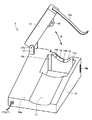
図2は、本発明の実施の形態における脈波測定装置用手首保持台の外観構造を示す図である。また、図3は、図2に示す脈波測定装置用手首保持台の手首保持部の構造を示す斜視図であり、図4は、図3に示すIV−IV線に沿った手首保持部の断面図である。 FIG. 2 is a diagram showing an external structure of the wrist holding base for the pulse wave measuring device according to the embodiment of the present invention. 3 is a perspective view showing the structure of the wrist holding portion of the wrist holding base for the pulse wave measuring device shown in FIG. 2, and FIG. 4 is a view of the wrist holding portion along the line IV-IV shown in FIG. It is sectional drawing.
まず、図2を参照して、本実施の形態における脈波測定装置用手首保持台の外観構造について説明する。図2に示すように、本実施の形態における脈波測定装置用手首保持台2は、テーブル等の載置面に載置される保持台本体10を有している。保持台本体10は、扁平な略直方体形状の外形を有しており、その上面10aはなだらかに傾斜しており、手前側(被験者側)が低く、奥側に向かうに連れて徐々にその高さが高くなるように形成されている。保持台本体10の上面10aの所定位置には、前腕を受け入れるための凹部11が設けられている。凹部11は、前腕がフィットし易いように緩やかな曲面形状を有している。
First, with reference to FIG. 2, the external structure of the wrist holding base for a pulse wave measuring device in the present embodiment will be described. As shown in FIG. 2, the wrist holding table 2 for pulse wave measuring device in the present embodiment has a holding
保持台本体10の凹部11の延びる方向の延長線上には、手首を保持するための手首保持部12が位置している。手首保持部12は、保持台本体10とは別体の部材にて構成されており、保持台本体10に着脱自在に取付けられる。より具体的には、手首保持部12は、その側面にガイド溝が設けられることによって保持台本体10に設けられた支柱部10b,10cのガイドレールに嵌め込み可能に構成されている。なお、手首保持部12の具体的な構造については後述することとする。
A
保持台本体10は、その上面10aの所定位置に回動アーム17を有している。具体的には、保持台本体10の手首保持部12が取付けられた位置の左側方に、保持台本体10の上面10aから上方に向かって軸支部16が突設されており、この軸支部16によって回動アーム17の長手方向の一方端に設けられた回動軸17aが軸支されている。これにより、回動アーム17は、保持台本体10に対して回動軸17aを中心軸として図中矢印R方向に回動することになり、保持台本体10に手首が載置された状態において手首を保持台本体10との間で挟み込むことが可能になる。なお、ここで、回動アーム17の回動軸17aは、保持台本体10に載置された手首の軸方向と平行な方向に延在するように配置される。
The holding
回動アーム17の下面の所定位置には、脈波検出部18が設けられている。脈波検出部18は、脈波を検出するための脈波センサ38(図5参照)と、この脈波センサ38を手首に向けて押圧するための押圧カフ31(図5参照)とを備えている。脈波センサ38としては、たとえば静電容量素子を具備した圧力センサや歪抵抗素子を具備した圧力センサ、生体インピーダンスを計測することが可能なインピーダンス計測センサ等が利用可能である。また、押圧カフ31としては、好適には内部に気体や液体が導入可能な流体袋が利用可能であるが、その他にもモータやソレノイド等の機械式アクチュエータを用いることも可能である。
A
回動アーム17の長手方向の他方端には、面ファスナ19aが取付けられており、保持台本体10の側面の所定位置には、上記面ファスナ19aに係合する面ファスナ19bが取付けられている。これら面ファスナ19a,19bは、互いに接触することによって係止可能であり、保持台本体10に載置された手首を回動アーム17と保持台本体10とによって挟み込んだ状態において当該状態を維持する手段として機能する。より具体的には、面ファスナ19a,19bは、保持台本体10に載置された手首を回動アーム17と保持台本体10とによって挟み込んだ状態において回動アーム17が保持台本体10から遠ざかる方向に移動することを制限する部材として機能し、これにより手首に対する脈波検出部18の適切な押圧状態を維持するものである。
A
なお、本実施の形態における脈波測定装置は、上述の脈波測定装置用手首保持台2に加え、外部端末としてのPC(personal computer)3(図5参照)を備えている。外部端末としてのPC3は、主として上述の脈波検出部18によって検出された情報を基に演算処理を行い、これによって脈波を得るための装置である。脈波測定装置用手首保持台2とPC3とは、たとえばUSB(universal serial bus)ケーブル等の接続ケーブルによって接続されるが、本実施の形態における脈波測定装置においては、脈波測定装置用手首保持台2の前面に設けられた入出力端子に上記接続ケーブルが接続されることにより、脈波測定装置用手首保持台2とPC3との結線が行なわれる。
The pulse wave measuring device according to the present embodiment includes a PC (personal computer) 3 (see FIG. 5) as an external terminal in addition to the above-described
次に、図3および図4を参照して、本実施の形態における脈波測定装置用手首保持台の手首保持部の構造について説明する。図3に示すように、手首保持部12は、略直方体形状の外形を有する箱状の部材にて構成されている。手首保持部12の上面には、左手の甲側に対応する部分の手首を受け入れ可能な窪み形状の溝13が設けられている。溝13の表面は、手首保持部12に手首が載置された状態において手首の周方向に沿う方向に延びる稜線13aを境とする2つの傾斜面を有している。
Next, with reference to FIG. 3 and FIG. 4, the structure of the wrist holding part of the wrist holding base for the pulse wave measuring device in the present embodiment will be described. As shown in FIG. 3, the
これら2つの傾斜面のうち、保持台本体10の手前側(被験者側)に位置する傾斜面は、手首保持部12に手首が載置された状態において手首の中枢側(すなわち前腕側)部分が宛がわれることによって当該部分を支持する中枢側手首支持面13bであり、保持台本体10の奥側に位置する傾斜面は、手首保持部12に手首が載置された状態において手首の末梢側部分が宛がわれることによってこれを支持する末梢側手首支持面13cである。
Of these two inclined surfaces, the inclined surface located on the front side (subject side) of the holding
それぞれの手首支持面13b,13cは、手首保持部12に手首が載置された状態において手首の軸方向と平行な方向に上記稜線13aから遠ざかるに連れてその高さが下方に向けて徐々に低くなるような形状にて形成されている。また、それぞれの手首支持面13b,13cは、手首保持部12に手首が載置された状態において手首の周方向に沿う方向に湾曲した形状を有しており、溝13内に左手の手首を受け入れた状態において手首の掌側に対応する部分が上方を向きかつ手首の橈骨側端部が手首の尺骨側端部よりも上方に位置するように手首を傾斜姿勢にて保持可能な形状に形成されている。より具体的には、溝13の表面は、手首の軸方向と交差する方向に左右非対称に(左右の曲率が異なるように)形成されている。
The respective wrist support surfaces 13b and 13c are gradually lowered in height as they move away from the
中枢側手首支持面13bの所定位置には、2つの手首検出部14A,14Bが設けられている。一方、末梢側手首支持面13cの所定位置には、1つの手首検出部14Cが設けられている。これら手首検出部14A〜14Cは、いずれも手首保持部12内に配置された投光素子としてのLED(light-emitting diode)15aと受光素子としてのPD(photodiode)15bとを含む光学センサにて構成されている。より具体的には、溝13の表面(すなわち、中枢側手首支持面13bおよび末梢側手首支持面13c)に透光性の窓部を設け、この透光性の窓部に対応して位置するように手首保持部12内にLED15aおよびPD15bが配置されている。
Two
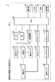
図5は、本発明の実施の形態における脈波測定装置の機能ブロックを示す図である。なお、図5においては、脈波測定装置の外部端末としてのPCについても図示している。次に、この図を参照して、本実施の形態における脈波測定装置の機能ブロックについて説明する。 FIG. 5 is a diagram showing functional blocks of the pulse wave measurement device according to the embodiment of the present invention. FIG. 5 also shows a PC as an external terminal of the pulse wave measuring device. Next, functional blocks of the pulse wave measurement device according to the present embodiment will be described with reference to this figure.
図5に示すように、脈波測定装置1は、脈波測定装置用手首保持台2とPC3とによって構成されており、それぞれに各種機能ブロックが構成されている。脈波測定装置用手首保持台2には、上述のように脈波検出部18が設けられており、当該脈波検出部18には、脈波センサ38と、この脈波センサ38が出力する複数の電圧信号を時分割多重し選択的に導出する信号抽出部としてのマルチプレクサ39と、脈波センサ38を手首に押圧するために加圧調整される押圧カフ31とが設けられている。
As shown in FIG. 5, the pulse wave measuring device 1 is composed of a pulse wave measuring
脈波測定装置用手首保持台2の保持台本体10には、上記の他に、押圧カフ31の内圧(以下、カフ圧とも言う。)を昇圧させるための加圧ポンプ32と、当該内圧を降圧させるための負圧ポンプ33と、加圧ポンプ32と負圧ポンプ33のいずれかを選択的に押圧カフ31に接続するための切替弁34と、これら加圧ポンプ32、負圧ポンプ33および切替弁34の動作を制御するための制御回路35と、押圧カフ31内の圧力を検出する圧力センサ36と、圧力センサ36から導出されたアナログ信号をデジタル信号に変換するためのA/Dコンバータ37と、脈波検出部18から導出されたアナログ信号をデジタル信号に変換するためのA/Dコンバータ40と、手首検出部14A〜14Cを構成するLED15aおよびPD15bとが設けられている。なお、図5中においては、LED15aおよびPD15bを各々1つずつしか図示していないが、実際には手首検出部の数(本実施の形態においては3つ)に対応した数だけLED15aおよびPD15bが具備されることになる。
In addition to the above, the holding
PC3は、脈波測定装置1を集中的に制御するための演算を含む各種演算処理を実行する演算処理部としてのCPU(central processing unit)41と、脈波測定装置を制御するためのデータおよびプログラムを記憶するROM(read only memory)42およびRAM(random access memory)43と、外部から操作可能に設けられて各種情報を入力するために操作される操作部44と、脈波測定結果などの各種情報を外部出力するためのLCD(liquid crystal display)などからなる表示部45とを含む。
The
図6および図7は、本発明の実施の形態における脈波測定装置用手首保持台に左手の手首をセットする手順を示すための概略斜視図である。次に、これらの図を参照して、本実施の形態における脈波測定装置用手首保持台に左手の手首をセットする手順について説明する。 6 and 7 are schematic perspective views for illustrating a procedure for setting the wrist of the left hand on the wrist holder for the pulse wave measuring device according to the embodiment of the present invention. Next, with reference to these drawings, a procedure for setting the wrist of the left hand on the wrist support base for the pulse wave measurement device according to the present embodiment will be described.
まず、脈波測定装置用手首保持台2をテーブル等の載置面上に載置する。つづいて、図6に示すように、保持台本体10の上面10aに設けられた凹部11上に肘から手首52に掛けての前腕53を載置する。このとき、左手51の甲側に対応する部分の手首52が手首保持部12の溝13に位置決めされて配置されるようにする。より具体的には、手首52の手関節前面横紋52aを目印として、この手関節前面横紋52aが溝13よりも僅かに奥側に位置するようにする。これにより、橈骨動脈の脈動が皮膚上において顕著に現れる被測定部位100が溝13上に位置するようになる。
First, the
ここで、本実施の形態における脈波測定装置用手首保持台2においては、上述のように左手51の手首52の保持に適した状態となるように手首保持部12の溝13が形成されているため、図6に示すように、保持台本体10に左手51の手首52を載置した状態において左手51の掌側に対応する部分の手首52が上方を向きかつ手首52の橈骨側端部PAが手首52の尺骨側端部PBよりも上方に位置するように、手首保持部12が手首52を傾斜姿勢にて保持する。したがって、上述の橈骨動脈の脈動が皮膚上において顕著に現れる被測定部位100がほぼ水平な状態に維持されることになる。そのため、脈波センサ38のセンサ面と被測定部位100との平行度を保つことが可能になり、測定精度の向上に資することとなる。
Here, in the
次に、図7に示すように、回動アーム17を保持台本体10側に向けて回動させ、保持台本体10の手首保持部12上に載置した手首52が回動アーム17と保持台本体10とによって挟み込まれるようにし、回動アーム17の下面に設けられた脈波検出部18を被測定部位100に接触させる。このとき、上述の位置決めが不十分であれば、凹部11に載置した前腕53および手首52の位置を微調節し、被測定部位100に脈波検出部18が接触するようにする。つづいて、回動アーム17に取付けられた面ファスナ19aを保持台本体10に取付けられた面ファスナ19bに係止させ、回動アーム17を保持台本体10に対して移動不能に固定する。以上により、左手51の手首52の脈波測定装置用手首保持台2へのセットが完了する。
Next, as shown in FIG. 7, the
図8(A)は、上述の装着手順を経ることにより正しい手首の保持姿勢が維持された場合の手首の保持状態を示す概略斜視図であり、図8(B)は、図8(A)に示すVIIIB−VIIIB線に沿った概略断面図である。なお、図8(B)は、左手首の断面を末梢側から中枢側に向けて見た場合の図である。一方、図9(A)は、正しい手首の保持姿勢となっていない場合の手首の保持状態の一例を示す概略斜視図であり、図9(B)は、図9(A)に示すXIB−XIB線に沿った概略断面図である。なお、図9(B)は、左手首の断面を末梢側から中枢側に向けて見た場合の図である。図9(A)および図9(B)に示す状態は、正しい手首の保持状態に比べて手首が被験者側にずれた場合の手首の保持状態を示すものである。以下においては、これらの図を参照して、手首の保持姿勢と手首検出部との相関関係について説明する。 FIG. 8A is a schematic perspective view showing a wrist holding state when a correct wrist holding posture is maintained through the above-described mounting procedure, and FIG. 8B is a schematic perspective view of FIG. It is a schematic sectional drawing in alignment with the VIIIB-VIIIB line | wire shown in FIG. FIG. 8B is a view when the cross section of the left wrist is viewed from the distal side toward the central side. On the other hand, FIG. 9 (A) is a schematic perspective view showing an example of a wrist holding state when the correct wrist holding posture is not taken, and FIG. 9 (B) is an XIB- shown in FIG. 9 (A). It is a schematic sectional drawing in alignment with the XIB line. In addition, FIG. 9B is a view when the cross section of the left wrist is viewed from the distal side toward the central side. The state shown in FIGS. 9A and 9B shows the wrist holding state when the wrist is displaced toward the subject as compared to the correct wrist holding state. In the following, the correlation between the wrist holding posture and the wrist detection unit will be described with reference to these drawings.
図8(A)および図8(B)に示すように、手首52が正しい保持姿勢で手首保持部12に載置された状態においては、左手51の甲側に対応する部分の手首52のうちの中枢側(前腕53側)の部分が手首保持部12の溝13の中枢側手首支持面13bに宛がわれた状態となり、左手51の甲側に対応する部分の手首52のうちの末梢側(左手51側)の部分が手首保持部12の溝13の末梢側手首支持面13cに宛がわれた状態となる。すなわち、左手51の手首52を甲側にやや傾けた状態でその姿勢が手首保持部12によって保持されることになる。
As shown in FIGS. 8A and 8B, when the
この状態において、左手51の甲側に対応する部分の手首52の表面は、中枢側手首支持面13bおよび末梢側手首支持面13cに接触し、手首検出部14A〜14Cに対応して設けられた透光性の窓部がすべて手首52によって覆われることになる。この状態においては、図8(B)に示すように、LED15aから発せられた光が左手51の手首52の表面において反射し、PD15bによってその反射光が受光されることになる。したがって、手首検出部14A〜14Cによって左手51の手首52が溝13の表面に正しく宛がわれていることが検出されることになる。
In this state, the surface of the
一方、図9(A)および図9(B)に示すように、正しい手首の保持状態に比べて手首52が被験者側にずれた場合の手首52の保持状態においては、左手51の甲側に対応する部分の手首52のうちの中枢側(前腕53側)の部分が手首保持部12の溝13の中枢側手首支持面13bに宛がわれた状態となる一方、左手51の甲側に対応する部分の手首52のうちの末梢側(左手51側)の部分が手首保持部12の溝13の末梢側手首支持面13cに宛がわれていない状態となる。すなわち、左手51の手首52が被験者側にずれることにより、図9(B)に示すように、末梢側手首支持面13cと手首52の末梢側の部分との間に距離Dが生じることになる。
On the other hand, as shown in FIGS. 9 (A) and 9 (B), in the holding state of the
この状態においては、手首検出部14CにおいてLED15aから発せられた光が散乱してしまい十分な強度の光がPD15bに到達しなくなる。したがって、手首検出部14Cにおいて左手51の手首52が溝13の表面に正しく宛がわれていないことが検出されることになる。
In this state, light emitted from the
このように、本実施の形態における脈波測定装置用手首保持台2およびこれを備えた脈波測定装置1においては、手首検出部14A〜14Cによって左手51の手首52が溝13の表面に正しく宛がわれているか否かが検出可能となり、左手51の手首52の保持状態が脈波測定に適したものとなっているか否かを判別することが可能になる。ここで、手首検出部14A〜14Cが手首保持部12の溝13の中枢側手首支持面13bおよび末梢側手首支持面13cのそれぞれに1つ以上設けられているため、脈波測定に適した手首52を反らした状態が再現されているかを手首検出部14A〜14Cによって確実に検出することができるようになる。そのため、当該情報を利用すれば装着を容易化することができたり、手首52の姿勢が安定的に保持されるように被験者に促したりすることができる。
Thus, in the pulse wave measuring
本実施の形態における脈波測定装置1においては、PC3の表示部45に当該手首検出部14A〜14Cによる左手51の手首52の検出結果を表示可能としている。以下においては、本実施の形態における脈波測定装置1の処理手順や表示部45における表示例を具体的に示すことにより、当該手首検出部における検出結果を利用した場合の一例について説明する。
In the pulse wave measuring apparatus 1 in the present embodiment, the detection result of the
図10は、本発明の実施の形態における脈波測定装置における脈波測定のための処理手順を示すフローチャートである。また、図11は、本実施の形態における脈波測定装置の表示部における表示例を示す図である。次に、これらの図を参照して、本実施の形態における脈波測定装置の処理手順および表示部における表示例について説明する。なお、図10に示すフローチャートに従うプログラムとこのプログラム実行時に参照されるデータはROM42またはRAM43に予めストアされており、CPU41がこのデータを適宜参照しながらプログラムを読出し実行することにより、脈波測定処理が進行する。
FIG. 10 is a flowchart showing a processing procedure for pulse wave measurement in the pulse wave measurement device according to the embodiment of the present invention. Moreover, FIG. 11 is a figure which shows the example of a display in the display part of the pulse-wave measuring apparatus in this Embodiment. Next, with reference to these drawings, a processing procedure of the pulse wave measurement device according to the present embodiment and a display example on the display unit will be described. The program according to the flowchart shown in FIG. 10 and the data to be referred to when executing the program are stored in the
図10に示すように、電源スイッチ(図示せず)がONされると、CPU41は制御回路35に対して負圧ポンプ33を駆動するように指示する。制御回路35は、この指示に基づいて切替弁34を負圧ポンプ33側に切替えて負圧ポンプ33を駆動する(ステップS1)。負圧ポンプ33が駆動されると切替弁34を介してカフ圧を大気圧よりも十分に低くするように作用するので、脈波センサ38は脈波検出部18内において上方に移動する。その結果、脈波センサ38が不用意に突出して誤動作や故障するのを回避できる。
As shown in FIG. 10, when a power switch (not shown) is turned ON, the
次に、被験者が前述した図6および図7に示した装着手順によって脈波検出部18を手首に装着する。このとき、CPU41は手首検出部14A〜14CとしてのLED15aおよびPD15bからなる光学センサを駆動し、左手51の手首52に向けて光を照射してその反射光が検出されるか否かを監視する(ステップS2)。
Next, the subject wears the
手首検出部14A〜14CのすべてにおいてPD15bによってLED15aから出射された光の反射光が所定量以上検出されない場合には(ステップS2でNO)、CPU41は手首が手首保持部12に正しく載置されていないと判断し、PC3の表示部45にエラー表示を行なうことによって被験者に手首が正しくセットされていないことを報知する(ステップS3)。たとえば、図11(A)は、手首検出部14A〜14Cのいずれにおても手首が検出されなかった場合の表示例であり、手首検出部14A〜14Cに対応するシグナルSA〜SCのいずれもが非点灯となることより、被験者に対して左手の手首を手首保持部12に載置するように促す。また、図11(B)は、手首検出部14A,14Bにおいて手首が検出されたものの手首検出部14Cにおいて手首が検出されなかった場合の表示例であり、手首検出部14A,14Bに対応するシグナルSA,SBは点灯するものの手首検出部14Cに対応するシグナルSCが非点灯となることにより、被験者に対して手首の保持姿勢を是正するように促す。
If the reflected light of the light emitted from the
一方、手首検出部14A〜14CのすべてにおいてPD15bによってLED15aから出射された光の反射光が所定量以上検出された場合には(ステップS2でYES)、CPU41は手首が手首保持部12に正しく載置されていると判断し、PC3の表示部45においてその旨を表示する。図11(C)は、手首の正しい保持姿勢が実現され、そのため手首検出部14A〜14Cのいずれにおても手首が検出された場合の表示例であり、手首検出部14A〜14Cに対応するシグナルSA〜SCのいずれもが点灯することにより、被験者に対して脈波測定に移行することが可能であることを報知する。
On the other hand, if the reflected light of the light emitted from the
図10に示すように、ステップS2において手首が検出された場合(ステップS2でYES)には、スタートボタン(図示せず)がONされることを待ってCPU41は制御回路35に対し加圧ポンプ32を駆動するように指示する。これにより、制御回路35はこの指示に基づいて切替弁34を加圧ポンプ32側に切替えて加圧ポンプ32を駆動する(ステップS4)。この動作に伴ってカフ圧は上昇し、脈波センサ38が手首に向かって下降して被測定部位である手首の表面に押圧される。
As shown in FIG. 10, when a wrist is detected in step S2 (YES in step S2), the
脈波センサ38が手首の表面に押圧されると、圧力センサ36からカフ圧情報が導出され、A/Dコンバータ37でデジタル情報に変換されて、CPU41に与えられる。同時に、脈波センサ38から得られる脈波信号もマルチプレクサ39を介してA/Dコンバータ40でデジタル情報に変換されてCPU41に与えられる。CPU41は、これらのデジタル情報に基づいて脈波検出のための条件が満たされたか否かを判定する(ステップS5)。脈波検出のための条件が満たされた場合には(ステップS5でYES)、押圧カフ31による脈波センサ38の被測定部位への押圧レベルが脈波検出のための最適レベルとなるように、加圧ポンプ32の出力が調整される(ステップS6)。押圧カフ31について最適圧力調整がなされる下で、脈波センサ38が出力する圧力情報、すなわち橈骨動脈の脈波の波形データは、マルチプレクサ39およびA/Dコンバータ40を介してCPU41に転送される(ステップS7)。
When the
CPU41は、波形データを受理して、受理した波形データに基づき脈波を検出する。波形データを受理して脈波検出終了の所定条件が成立したと判定するまではステップS7の脈波データの転送処理が繰り返される。なお、受理した波形データに基づく脈波検出処理は公知の手順に従うので、ここではその詳細は略す。脈波検出終了の所定条件が成立したときは(ステップS8でYES)、CPU41は切替弁34を介して負圧ポンプ33を駆動するように制御する(ステップS9)。これにより、手首に対する脈波センサ38の押圧状態は解かれて、一連の脈波検出処理は終了する。
The
なお、CPU41は、検出した脈波の情報を表示部45などを介して外部に出力する。その際、脈波の情報は、AI(Augmentation Index)値として出力されるようにしてもよい。
The
以上において説明したように、本実施の形態の如くの脈波測定装置用手首保持台2を備えた脈波測定装置1とすることにより、装着が容易でかつ手首の姿勢を安定的に保持することが可能であるとともに脈波の測定精度が低下しない脈波測定装置とすることができる。
As described above, the pulse wave measuring device 1 including the pulse wave measuring
上述の本発明の一実施の形態においては、手首検出部としてLEDおよびPDを含む光学センサを採用した場合を例示して説明を行なったが、これ以外の手段を用いることも可能である。たとえば、図12に示すように、接触式のマイクロスイッチ15cを手首検出部として利用することも可能である。この場合には、マイクロスイッチ15cが手首保持部12の溝13に載置された手首に接触するように、溝13に開口部を設けて当該開口部からスイッチの先端が溝13の表面から僅かに突出するように配置させることが必要である。
In the above-described embodiment of the present invention, the case where an optical sensor including an LED and a PD is employed as the wrist detection unit has been described as an example. However, other means may be used. For example, as shown in FIG. 12, a contact-
また、上述の本発明の一実施の形態においては、手首検出部を手首保持部に3箇所設けた場合を例示して説明を行なったが、手首検出部の数は特に制限されるものではない。また、その配置位置も適宜変更可能である。 Further, in the above-described embodiment of the present invention, the case where the wrist detecting unit is provided at three positions on the wrist holding unit has been described as an example, but the number of wrist detecting units is not particularly limited. . Further, the arrangement position can be changed as appropriate.
また、上述の本発明の一実施の形態においては、手首検出部の検出結果を表示部にてシグナルで表示させる場合を例示して説明を行なったが、表示部においてガイダンスの文章を表示させたり、音や音声等によって被験者に報知したりすることも可能である。 Further, in the above-described embodiment of the present invention, the case where the detection result of the wrist detection unit is displayed as a signal on the display unit has been described as an example, but guidance text may be displayed on the display unit. It is also possible to notify the subject by sound or voice.
また、上述の本発明の一実施の形態においては、脈波測定前において手首検出部によって手首が正しい保持姿勢となった場合にのみ脈波測定が可能となるように構成した場合を例示して説明を行なったが、測定中においても手首検出部によって手首が正しい保持姿勢にあるか否かを常時監視し、手首の保持姿勢に問題が生じた場合に脈波測定を中断して測定に失敗したことを被験者に報知したり、測定は続行するものの測定結果の信頼性に問題があることを被験者に報知するように装置を構成してもよい。 In the above-described embodiment of the present invention, a case where the pulse wave measurement is configured to be possible only when the wrist is in the correct holding posture by the wrist detection unit before the pulse wave measurement is illustrated. Although explained, the wrist detection unit constantly monitors whether the wrist is in the correct holding posture even during measurement, and if there is a problem with the wrist holding posture, the pulse wave measurement is interrupted and the measurement fails The apparatus may be configured to notify the subject that the test has been performed, or to notify the subject that there is a problem with the reliability of the measurement result although the measurement continues.
さらには、上述の本発明の一実施の形態においては、左手の手首を脈波測定のための被測定部位として利用することができるように構成された脈波測定装置用手首保持台およびこれを備えた脈波測定装置を例示して説明を行なったが、右手の手首を脈波測定のための被測定部位として利用することができるように構成された脈波測定装置用手首保持台およびこれを備えた脈波測定装置に本発明を適用することも当然に可能であるし、左手の手首および右手の手首のいずれをも脈波測定のための被測定部位として利用することができるように構成された脈波測定装置用手首保持台およびこれを備えた脈波測定装置に本発明を適用することも可能である。 Furthermore, in the above-described embodiment of the present invention, the wrist holding base for the pulse wave measuring device configured to be able to use the wrist of the left hand as a measurement site for pulse wave measurement, Although the pulse wave measuring device provided is described as an example, the wrist holding base for the pulse wave measuring device configured to be able to use the wrist of the right hand as a measurement site for pulse wave measurement and the same Naturally, it is possible to apply the present invention to a pulse wave measuring device equipped with a device such that either the wrist of the left hand or the wrist of the right hand can be used as a measurement site for pulse wave measurement. It is also possible to apply the present invention to the constructed wrist holder for a pulse wave measuring device and the pulse wave measuring device including the same.
このように、今回開示した上記一実施の形態はすべての点で例示であって、制限的なものではない。本発明の技術的範囲は特許請求の範囲によって画定され、また特許請求の範囲の記載と均等の意味および範囲内でのすべての変更を含むものである。 Thus, the one embodiment disclosed this time is illustrative in all respects and is not restrictive. The technical scope of the present invention is defined by the terms of the claims, and is intended to include any modifications within the scope and meaning equivalent to the terms of the claims.
1 脈波測定装置、2 脈波測定装置用手首保持台、3 PC、10 保持台本体、10a 上面、10b,10c 支柱部、11 凹部、12 手首保持部、13 溝、13a 稜線、13b 中枢側手首支持面、13c 末梢側手首支持面、14A〜14C 手首検出部、15a LED、15b PD、15c マイクロスイッチ、16 軸支部、17 回動アーム、17a 回動軸、18 脈波検出部、19a,19b 面ファスナ、31 押圧カフ、32 加圧ポンプ、33 負圧ポンプ、34 切替弁、35 制御回路、36 圧力センサ、37 A/Dコンバータ、38 脈波センサ、39 マルチプレクサ、40 A/Dコンバータ、41 CPU、42 ROM、43 RAM、44 操作部、45 表示部、51 左手、51a 親指、51b 小指、52a 手関節前面横紋、52 手首、53 前腕、56 橈骨、56a 橈骨茎状突起、57 尺骨、57a 尺骨茎状突起、58 橈骨動脈、100 被測定部位。
DESCRIPTION OF SYMBOLS 1 Pulse wave measuring device, 2 Wrist holder for pulse wave measuring devices, 3 PC, 10 Main body of holding base, 10a Upper surface, 10b, 10c Strut part, 11 Recessed part, 12 Wrist holding part, 13 Groove, 13a Ridge line, 13b Central side Wrist support surface, 13c distal wrist support surface, 14A to 14C wrist detection unit, 15a LED, 15b PD, 15c microswitch, 16 shaft support unit, 17 rotation arm, 17a rotation axis, 18 pulse wave detection unit, 19a, 19b surface fastener, 31 pressure cuff, 32 pressure pump, 33 negative pressure pump, 34 switching valve, 35 control circuit, 36 pressure sensor, 37 A / D converter, 38 pulse wave sensor, 39 multiplexer, 40 A / D converter, 41 CPU, 42 ROM, 43 RAM, 44 operation unit, 45 display unit, 51 left hand, 51a thumb, 51b small , 52a wrist front striated, 52 wrist, 53
Claims (7)
前記保持台本体の上部に設けられ、手首が載置されることによって手首の姿勢を保持することが可能な窪み形状の溝を含む手首保持部と、
前記手首保持部に設けられ、前記溝の表面に手首が宛がわれているか否かを検出する手首検出部とを備え、
前記溝は、前記手首保持部に手首が載置された状態において手首の中枢側部分が宛がわれる中枢側手首支持面と、前記手首保持部に手首が載置された状態において手首の末梢側部分が宛がわれる末梢側手首支持面とを含み、
前記中枢側手首支持面と前記末梢側手首支持面とは、前記溝の表面に手首が沿うように宛がわれることで手首を反らした姿勢で保持することが可能となるように互いに異なる方向を向いて配置され、
前記手首検出部が、前記中枢側手首支持面および前記末梢側手首支持面のそれぞれに少なくとも1つ以上設けられている、脈波測定装置用手首保持台。 A holding base body mounted on the mounting surface;
A wrist holding portion including a recess-shaped groove provided on the upper portion of the holding base body and capable of holding the posture of the wrist by placing the wrist;
A wrist detection unit that is provided in the wrist holding unit and detects whether or not the wrist is addressed to the surface of the groove;
The groove includes a central wrist support surface to which a central part of the wrist is addressed when the wrist is placed on the wrist holding portion, and a distal side of the wrist when the wrist is placed on the wrist holding portion. A peripheral wrist support surface to which the part is addressed,
The central wrist support surface and the distal wrist support surface are arranged in different directions so that the wrist can be held in a warped posture by being placed so that the wrist is along the surface of the groove. Placed facing
A wrist holding base for a pulse wave measurement device, wherein at least one wrist detection unit is provided on each of the central wrist support surface and the distal wrist support surface.
前記中枢側手首支持面と前記末梢側手首支持面とは、前記稜線を境として互いに前記稜線から手首の軸方向に遠ざかるに連れて下方に向けて傾斜するように構成されている、請求項1から3のいずれかに記載の脈波測定装置用手首保持台。 The groove extends in a direction along the circumferential direction of the wrist in a state where the wrist is placed on the wrist holding portion, and has a ridge line serving as a boundary between the central wrist support surface and the distal wrist support surface on a surface thereof. Have
The central wrist support surface and the distal wrist support surface are configured to incline downward from the ridge line toward the axial direction of the wrist with respect to the ridge line as a boundary. To 3. The wrist holder for the pulse wave measuring device according to any one of items 1 to 3.
請求項1から5のいずれかに記載の脈波測定装置用手首保持台とを備えた、脈波測定装置。 A pulse wave detector for detecting a pulse wave;
A pulse wave measuring device comprising the wrist holding base for the pulse wave measuring device according to claim 1.
Priority Applications (3)
| Application Number | Priority Date | Filing Date | Title |
|---|---|---|---|
| JP2006243148A JP4626593B2 (en) | 2006-09-07 | 2006-09-07 | Wrist holder for pulse wave measuring device and pulse wave measuring device provided with the same |
| PCT/JP2007/066242 WO2008029617A1 (en) | 2006-09-07 | 2007-08-22 | Wrist holding base for pulse wave measuring instrument and pulse wave measuring instrument having the same |
| TW96133012A TW200816957A (en) | 2006-09-07 | 2007-09-05 | Wrist maintenance stand for pulsometer and pulsometer with the wrist maintenance stand |
Applications Claiming Priority (1)
| Application Number | Priority Date | Filing Date | Title |
|---|---|---|---|
| JP2006243148A JP4626593B2 (en) | 2006-09-07 | 2006-09-07 | Wrist holder for pulse wave measuring device and pulse wave measuring device provided with the same |
Publications (3)
| Publication Number | Publication Date |
|---|---|
| JP2008061831A JP2008061831A (en) | 2008-03-21 |
| JP2008061831A5 JP2008061831A5 (en) | 2009-10-08 |
| JP4626593B2 true JP4626593B2 (en) | 2011-02-09 |
Family
ID=39157053
Family Applications (1)
| Application Number | Title | Priority Date | Filing Date |
|---|---|---|---|
| JP2006243148A Expired - Fee Related JP4626593B2 (en) | 2006-09-07 | 2006-09-07 | Wrist holder for pulse wave measuring device and pulse wave measuring device provided with the same |
Country Status (3)
| Country | Link |
|---|---|
| JP (1) | JP4626593B2 (en) |
| TW (1) | TW200816957A (en) |
| WO (1) | WO2008029617A1 (en) |
Families Citing this family (4)
| Publication number | Priority date | Publication date | Assignee | Title |
|---|---|---|---|---|
| KR101029785B1 (en) | 2009-09-08 | 2011-04-19 | 한국생산기술연구원 | Device for Measurement for Blood Pressure |
| DE112010003588B4 (en) | 2009-09-08 | 2018-07-19 | Korea Institute Of Industrial Technology | Device for measuring biometric information |
| TW202025962A (en) * | 2018-11-23 | 2020-07-16 | 香港商愛脈(智慧財產)有限公司 | A physiological measurement device and a method thereof |
| WO2023021970A1 (en) * | 2021-08-19 | 2023-02-23 | 株式会社村田製作所 | Biosensor and biological information measuring system |
Citations (5)
| Publication number | Priority date | Publication date | Assignee | Title |
|---|---|---|---|---|
| JPS57200203U (en) * | 1981-06-15 | 1982-12-20 | ||
| JPS61238230A (en) * | 1985-04-15 | 1986-10-23 | オムロン株式会社 | Digital hemomanometer |
| JPS63158039A (en) * | 1986-05-02 | 1988-07-01 | エドワ−ド エイチ ホン | Blood pressure measuring apparatus |
| JPH07124128A (en) * | 1993-10-29 | 1995-05-16 | Nippon Colin Co Ltd | Automatic winding device for arm band for blood pressure measurement |
| JP2005087483A (en) * | 2003-09-17 | 2005-04-07 | Omron Healthcare Co Ltd | Wrist fixing tool for pulse wave measuring device and pulse wave measuring device |
-
2006
- 2006-09-07 JP JP2006243148A patent/JP4626593B2/en not_active Expired - Fee Related
-
2007
- 2007-08-22 WO PCT/JP2007/066242 patent/WO2008029617A1/en active Search and Examination
- 2007-09-05 TW TW96133012A patent/TW200816957A/en unknown
Patent Citations (5)
| Publication number | Priority date | Publication date | Assignee | Title |
|---|---|---|---|---|
| JPS57200203U (en) * | 1981-06-15 | 1982-12-20 | ||
| JPS61238230A (en) * | 1985-04-15 | 1986-10-23 | オムロン株式会社 | Digital hemomanometer |
| JPS63158039A (en) * | 1986-05-02 | 1988-07-01 | エドワ−ド エイチ ホン | Blood pressure measuring apparatus |
| JPH07124128A (en) * | 1993-10-29 | 1995-05-16 | Nippon Colin Co Ltd | Automatic winding device for arm band for blood pressure measurement |
| JP2005087483A (en) * | 2003-09-17 | 2005-04-07 | Omron Healthcare Co Ltd | Wrist fixing tool for pulse wave measuring device and pulse wave measuring device |
Also Published As
| Publication number | Publication date |
|---|---|
| TW200816957A (en) | 2008-04-16 |
| JP2008061831A (en) | 2008-03-21 |
| WO2008029617A1 (en) | 2008-03-13 |
Similar Documents
| Publication | Publication Date | Title |
|---|---|---|
| JP5175846B2 (en) | Apparatus and method for non-invasively measuring hemodynamic parameters | |
| CN101703394B (en) | Radial pulse wave detection device | |
| CN100396234C (en) | Detector for measuring biological signal and biological measuring system including the same | |
| JP5176849B2 (en) | Blood pressure information display device, blood pressure information display system, blood pressure information display method, and blood pressure information display program | |
| JP4644993B2 (en) | Acupuncture point exploration device and treatment effect judgment device | |
| JP2008510516A (en) | Non-invasive measurement of hemodynamic parameters | |
| CN109069021B (en) | Pressure pulse wave detection device and biological information measurement device | |
| US20150196204A1 (en) | Apparatus and methods for non-invasively measuring hemodynamic parameters | |
| US20070167844A1 (en) | Apparatus and method for blood pressure measurement by touch | |
| JP6389904B2 (en) | Measuring device and sensor system | |
| JP4626593B2 (en) | Wrist holder for pulse wave measuring device and pulse wave measuring device provided with the same | |
| KR20170067131A (en) | Blood presure measurement apparatus and blood presure measuring method using the same | |
| KR102303972B1 (en) | Blood pressure pulse wave measuring device and program | |
| JP4452875B2 (en) | Arterial blood vessel detection device, pressure pulse wave detection device, and arteriosclerosis evaluation device | |
| KR101829335B1 (en) | Wrist Support united wireless mouse and stress measuring system | |
| JP2008061830A (en) | Pulse wave measuring apparatus | |
| JP2008061832A (en) | Pulse wave measuring apparatus | |
| WO2008004505A1 (en) | Pulse detecting device using sensor | |
| JP6506726B2 (en) | Biological information acquisition device | |
| KR20180108842A (en) | Blood pressure measuring device | |
| WO2019225585A1 (en) | Blood pressure measurement device | |
| JP2004113811A (en) | Pressure detector | |
| JP3835450B2 (en) | Pulse wave detector and pulsation detector | |
| JP2018143582A (en) | Blood pressure measurement device | |
| JP2009219540A (en) | Hemodynamometer |
Legal Events
| Date | Code | Title | Description |
|---|---|---|---|
| A521 | Written amendment |
Free format text: JAPANESE INTERMEDIATE CODE: A523 Effective date: 20090824 |
|
| A621 | Written request for application examination |
Free format text: JAPANESE INTERMEDIATE CODE: A621 Effective date: 20090824 |
|
| A131 | Notification of reasons for refusal |
Free format text: JAPANESE INTERMEDIATE CODE: A131 Effective date: 20100706 |
|
| A521 | Written amendment |
Free format text: JAPANESE INTERMEDIATE CODE: A523 Effective date: 20100902 |
|
| TRDD | Decision of grant or rejection written | ||
| A01 | Written decision to grant a patent or to grant a registration (utility model) |
Free format text: JAPANESE INTERMEDIATE CODE: A01 Effective date: 20101012 |
|
| A01 | Written decision to grant a patent or to grant a registration (utility model) |
Free format text: JAPANESE INTERMEDIATE CODE: A01 |
|
| A61 | First payment of annual fees (during grant procedure) |
Free format text: JAPANESE INTERMEDIATE CODE: A61 Effective date: 20101025 |
|
| FPAY | Renewal fee payment (event date is renewal date of database) |
Free format text: PAYMENT UNTIL: 20131119 Year of fee payment: 3 |
|
| R150 | Certificate of patent or registration of utility model |
Free format text: JAPANESE INTERMEDIATE CODE: R150 |
|
| LAPS | Cancellation because of no payment of annual fees |