JP4626065B2 - Deodorizing device for local body cleaning equipment - Google Patents
Deodorizing device for local body cleaning equipment Download PDFInfo
- Publication number
- JP4626065B2 JP4626065B2 JP2001046842A JP2001046842A JP4626065B2 JP 4626065 B2 JP4626065 B2 JP 4626065B2 JP 2001046842 A JP2001046842 A JP 2001046842A JP 2001046842 A JP2001046842 A JP 2001046842A JP 4626065 B2 JP4626065 B2 JP 4626065B2
- Authority
- JP
- Japan
- Prior art keywords
- deodorizing
- housing
- cartridge
- main body
- mounting
- Prior art date
- Legal status (The legal status is an assumption and is not a legal conclusion. Google has not performed a legal analysis and makes no representation as to the accuracy of the status listed.)
- Expired - Fee Related
Links
Images


Description
【0001】
【発明の属する技術分野】
この発明は、便器に設置されて人体局部を洗浄するのに使用される人体局部洗浄装置に係る。詳しくは、便器周りの臭気を脱臭する脱臭装置に関する。
【0002】
【従来の技術】
従来の人体局部洗浄装置は、洗浄ノズルによる人体局部の洗浄、洗浄後の温風ファンによる乾燥及びヒータによる便座の暖房等の主要機能の他に、使用時の便器周りの臭気を脱臭する脱臭装置による脱臭機能を備えている。この脱臭目的としては、主に、使用者自身の排便等の臭いを除去することと、直前に使用した別の使用者の臭いを除去することが挙げられる。この種の脱臭に関して、近年、関連業界では強い関心が持たれており、人体局部洗浄装置のみならず、他の家電製品でも有用視されている。
【0003】
人体局部洗浄装置の脱臭装置としては、トイレ室内や便器周りの臭気をファンにより吸引して脱臭剤を用いて物理的及び化学的に臭気成分を吸着除去する方式や、高電圧によりオゾンを発生させて臭気成分を分解除去する方式等が知られている。このうち脱臭剤を用いた方式は、構造が比較的単純で部品点数も比較的少ないことから、現在の市場での主流を占めている。この種の脱臭剤は消耗品であり、所定の使用期間毎に新しいものと交換する必要があることから、カートリッジ化されて洗浄装置本体に対して着脱自在に装着される構造のものが多く見られる。
【0004】
特開平5−202548号公報には、この種の脱臭装置の一例が開示されている。図14に示すように、この脱臭装置は、吸入口51と排出口52を有するダクト53と、ダクト53の内部に臭気を吸引するための送風機54と、ダクト53に装着されるカートリッジ化された脱臭ユニット55とを備える。脱臭ユニット55は、ダクト53の上面に設けられた投入口56に着脱自在に装着され、その装着状態では脱臭ユニット55の天板57により投入口56が塞がれるようになっている。
或いは、別のタイプとして、人体局部洗浄装置の本体ハウジングの上面や側面に投入口が設けられ、その投入口から投入された脱臭カートリッジが本体ハウジング内部に設けられた脱臭ハウジングに装着される構造の脱臭装置もある。この種のタイプでは、投入口に専用蓋が嵌め込まれている。
【0005】
【発明が解決しようとする課題】
ところが、前記従来の各脱臭装置では、脱臭ユニット55の天板57がダクト53の上面に露出したり、本体ハウジングの上面に専用蓋が露出したりすることから、これらによって人体局部洗浄装置の意匠が制約を受けることになった。又、トイレ室内での長期間の使用により、埃や汚水等が脱臭ユニット55の天板57や専用蓋の周囲の隙間に付着して汚れが目立つことがあり、人体局部洗浄装置の見栄えが損なわれることにもなった。特に、従来の各脱臭装置では、人体局部洗浄装置が通常使用される状態で、上記汚れが人目に触れることがあり、見栄えや衛生面で問題となっていた。
【0006】
この発明は上記事情に鑑みてなされたものであって、その目的は、見栄えを損なわず衛生的な人体局部洗浄装置の脱臭装置を提供することにある。
【0007】
【課題を解決するための手段】
上記目的を達成するために、請求項1に記載の発明は、便器に設置される本体ハウジングを備えた人体局部洗浄装置の脱臭装置であって、前記本体ハウジングに内蔵され、吸入口及び排出口を含む脱臭ハウジングと、前記吸入口から臭気を吸入させるために前記脱臭ハウジングに設けられる吸入ファンと、前記吸入口から吸入された臭気を脱臭するために前記脱臭ハウジングに着脱自在に装着される脱臭カートリッジと、前記脱臭カートリッジを着脱するために前記脱臭ハウジングの下側に設けられた着脱口と、前記脱臭カートリッジを装着するために前記脱臭ハウジングの上側に設けられた装着口とを備えること、前記装着口から前記脱臭カートリッジの装着を行った後、前記装着口が前記本体ハウジングにより塞がれることを趣旨とする。
【0008】
上記発明の構成によれば、脱臭カートリッジの着脱口が脱臭ハウジングの下側に設けられ、その着脱口が本体ハウジングの下面に開口されることから、本体ハウジングが便器に設置された状態で、着脱口が人目に触れることがない。また、洗浄装置の製造時には、脱臭ハウジングの上側に設けられた装着口から脱臭カートリッジを装着できるため、製造時における脱臭装置の組付作業を簡易なものにすることができる。
【0009】
上記目的を達成するために、請求項2に記載の発明は、請求項1に記載の発明において、脱臭カートリッジを脱臭ハウジングに対して選択的に係合又は離脱させるために脱臭カートリッジと脱臭ハウジングとに設けられた係脱手段を備えたことを趣旨とする。
【0010】
上記発明の構成によれば、請求項1に記載の発明の作用に加え、脱臭カートリッジが着脱口を通じて脱臭ハウジングの中に挿入されたとき、脱臭カートリッジは係脱手段の係合により脱臭ハウジングに保持されて装着される。従って、一旦装着された脱臭カートリッジが着脱口へ向けて落下することがない。一方、一旦装着された脱臭カートリッジを取り外すには、同カートリッジに力を加えて係脱手段を離脱させる。従って、保持が解かれた脱臭カートリッジが重力の作用を受けて着脱口から取り出される。
【0011】
上記目的を達成するために、請求項3に記載の発明は、請求項1又は請求項2に記載の発明において、本体ハウジングは、下面を含み脱臭ハウジングを支持する本体基盤と、脱臭ハウジングを覆い本体基盤に固定される本体カバーとから構成されることと、本体基盤から本体カバーが取り外された状態で、脱臭カートリッジを装着するために脱臭ハウジングの上側に設けられた装着口とを備えたことを趣旨とする。
【0012】
上記発明の構成によれば、請求項1又は請求項2に記載の作用に加え、製造時において、本体ハウジングの本体基盤に脱臭ハウジングが支持された状態で、その上側から装着口に脱臭カートリッジを挿入することにより、脱臭カートリッジが脱臭ハウジングに装着される。その後、本体カバーを本体基盤に取り付けることにより、脱臭ハウジングがその装着口と共に本体カバーにより覆われる。従って、製造時には、本体基盤の下面の着脱口から脱臭カートリッジを装着する必要がない。
【0013】
上記目的を達成するために、請求項4に記載の発明は、請求項3に記載の発明において、脱臭ハウジングに対する脱臭カートリッジの装着向きを規定するために脱臭カートリッジと装着口とに設けられた向き規定手段を備えたことを趣旨とする。
【0014】
上記発明の構成によれば、請求項3に記載の発明の作用に加え、脱臭カートリッジを装着口を通じて脱臭ハウジングに装着するとき、向き規定手段により脱臭ハウジングに対する脱臭カートリッジの装着向きが所要の向きに規定されることになる。従って、製造時に、向き規定手段により規定される向きで装着口から脱臭カートリッジを挿入することにより、常に所要の向きで脱臭カートリッジが脱臭ハウジングに装着されることになる。例えば、脱臭ハウジングの吸入口から排出口へ向かう臭気の流れを許容する構造が脱臭カートリッジに与えられている場合に、その構造を発揮させる向きで脱臭カートリッジを装着するために向き規定手段を構成することにより、常に必要な向きで脱臭カートリッジが脱臭ハウジングに誤りなく装着されることになる。
【0015】
【発明の実施の形態】
以下、本発明の人体局部洗浄装置の脱臭装置を具体化した一実施の形態を図面を参照して詳細に説明する。
【0016】
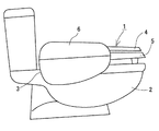
図1に人体局部洗浄装置(以下、単に「洗浄装置」と称する。)1の平面図を、図2に同装置1の側面図をそれぞれ示す。便器2の上に設置された洗浄装置1は、便器2の後部上面に設置された装置本体3と、装置本体3に回動可能に設けられた便蓋4及び便座5と、便座5の右側において装置本体3から張り出された操作装置6とを備える。便座5の後部下方において、装置本体3にはシャワーノズル7及びビデノズル8が設けられる。これらノズル7,8は、本発明の洗浄機能部品の一つに相当し、便座5に着座した使用者の局部を洗浄するために洗浄水を噴出するものである。この洗浄装置1は、両ノズル7,8による洗浄を含む洗浄関連機能の他に、温風ファン(図示略)による洗浄後の乾燥、便座ヒータ(図示略)による便座5の暖房、後述する脱臭装置9によるトイレ室内の脱臭等の洗浄に関連しない非洗浄関連機能を備えている。温水ヒータ、温風ファン及び脱臭装置9等は装置本体3に設けられる。便座ヒータは便座5の内部に設けられる。これら各機能は、主として操作装置6の操作パネル10に設けられたスイッチ類11が操作されることにより発揮される。
【0017】
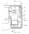
次に、脱臭装置9について説明する。図3に装置本体3の一側端部を破断して示す。図4に図3のA−A線に沿った断面図を示す。脱臭装置9は、装置本体3を構成する本体ハウジング12に内蔵された脱臭ハウジング13と、脱臭ハウジング13に内蔵された吸入ファン14と、同じく脱臭ハウジング13に着脱自在に装着された脱臭カートリッジ15とを備える。本体ハウジング12と脱臭ハウジング13は、それぞれ合成樹脂により形成される。
【0018】
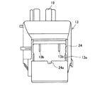
本体ハウジング12は、下面12aを含み脱臭ハウジング13を支持する本体基盤12Aと、脱臭ハウジング13を覆うと共に本体基盤12Aに固定された本体カバー12Bとから構成される。脱臭ハウジング13は、臭気を吸入するための吸入口16と、悪臭を除去した後の空気を排出するための排出口17とを含む。脱臭ハウジング13は、ネジ18等により本体基盤12Aに固定される。吸入ファン14は、吸入口16から臭気を吸入させるために作動するものでありモータ及びファン等により構成される。脱臭カートリッジ15は、吸入口16から吸入された臭気を脱臭するためのものである。脱臭ハウジング13の頂部に設けられた取付リブ19には、吸入ファン14への給電のための電源コネクタ20が接続される。吸入口16は、本体ハウジング12に設けられた所定の導入ダクト(図示略)に通じる。この導入ダクトは、便器2の内部へ開口する。
【0019】
図5に脱臭ハウジング13の平面図を、図6に図5の右側面図を、図7に図5の正面図をそれぞれ示す。図4〜7に示すように、脱臭ハウジング13の下側には、脱臭カートリッジ15を着脱するための着脱口21が設けられる。本体基盤12Aの下面12aには、着脱口21に対応して出入口22が設けられる。図4に示すように、着脱口21は出入口22を通じて本体基盤12Aの下面12aに開口される。この着脱口21は、着脱自在に装着される着脱蓋23により塞がれる。
【0020】
図4,5,7に示すように、脱臭ハウジング13の上側には、脱臭カートリッジ15を装着するだけのための装着口24が設けられる。この装着口24には蓋が設けられない。装着口24は、図4に示すように、本体カバー12Bに覆われることにより塞がれる。装着口24には、本体基盤12Aから本体カバー12Bが取り外された状態において脱臭カートリッジ15が装着されるようになっている。この装着口24の一辺には、一つの凹部24aが形成される。
【0021】
図8に脱臭カートリッジ15の斜視図を示す。図9に脱臭カートリッジ15の正面図を、図10に図9の左側面図を、図11に図9の平面図をそれぞれ示す。このカートリッジ15は、略立方体形状をなす合成樹脂製のケース25と、そのケース25に内蔵された所定の脱臭剤(図示略)とを備える。この実施の形態の脱臭カートリッジ15は、必要に応じて新品と交換することを前提に設けられたものである。しかし、この実施の形態で用いられる脱臭剤は、臭気成分を吸着するための持続力が比較的長く、一般家庭であれば数年間という長期にわたって使用することができるものである。従って、本来、脱臭カートリッジ15の交換を頻繁に行う必要はないといえる。
【0022】
ケース25の前面は、通気を許容するために、十字に形成されたリブ25aの間がメッシュ25bに形成される。ケース25の背面も前面と同様に形成される。ケース25の前面のリブ25aの中央には、上下方向に伸びる板状の摘み片25cが突設される。この摘み片25cは、使用者が脱臭カートリッジ15を取り扱う際に指先で摘まれる部分である。又、この摘み片25cは、上記装着口24の凹部24aに整合させるものでもある。即ち、脱臭カートリッジ15が装着口24から脱臭ハウジング13に装着されるとき、摘み片25cを凹部24aに整合させて案内するようになっている。これら凹部24a及び摘み片25cにより、脱臭ハウジング13に対する脱臭カートリッジ15の装着向きを規定するための本発明の向き規定手段が備される。この装着向きで脱臭カートリッジ15が脱臭ハウジング13に装着されることにより、同カートリッジ15の前面が同ハウジング13の吸入口16に向けて、その背面が吸入ファン14に向けてそれぞれ配置される。
【0023】
ケース25の左右両側面には、それぞれフック25dが一体形成される。両フック25dは自身のバネ力による可撓性を有する。ケース25の上下両側面は、それぞれ平坦に形成される。両フック25は、脱臭カートリッジ15が脱臭ハウジング13の中に装着された状態で、同カートリッジ15を同ハウジング13に対して選択的に係合又は離脱させるためのものである。脱臭ハウジング13の中の所定の部位の内壁には、両フック25dを係合させる段部13aが形成される。これらフック25d及び段部13aにより、本発明の係脱手段が構成される。
【0024】
この他、脱臭ハウジング13の内壁には、ガイドリブ13bが形成される。着脱蓋23には、同じくガイドリブ23aが形成される。これらガイドリブ13b,23aにより、脱臭カートリッジ15が所定の姿勢で案内されながら装着口24から挿入されるようになっている。又、脱臭ハウジング13に装着された脱臭カートリッジ15が、所定の姿勢で保持されるようになっている。
【0025】
以上説明したように本実施の形態の脱臭装置9によれば、所定の脱臭スイッチが操作されることにより、吸入ファン14が作動して脱臭ハウジング13の吸入口16から臭気が吸入される。この臭気は、所定の導入ダクトを通じて便器2の周りやトイレ室内から導入されるものである。吸入された臭気は、脱臭カートリッジ15をその前面から背面へ向かって流れ、その臭気成分が脱臭剤に吸着して除去される。その後、臭気成分が除去された空気は、吸入ファン14を通過して排出口17から外部へ排出される。このようにして便器2の周りやトイレ室内の臭気が好適に除去される。
【0026】
ここで、脱臭カートリッジ15を新品と交換する場合には、図12に示すように、本体ハウジング12の下面12aに位置する着脱口21から着脱蓋23を取り外す。そして、脱臭ハウジング13に装着されている古い脱臭カートリッジ15を着脱口21から取り出す。このとき、使用者は着脱口21から脱臭ハウジング13へ指を差し入れ、指先で摘み片25cを摘んで脱臭カートリッジ15を引き抜く。この引き抜きにより、脱臭ハウジング13の段部13aに係合していた脱臭カートリッジ15のフック25dが離脱して、同カートリッジ15の保持状態が解除される。
その後、新しい脱臭カートリッジ15を装着するには、摘み片25cを指先で摘みながらそのカートリッジ15を着脱口21から脱臭ハウジング13へ挿入する。このとき、両フック25dが段部13aに係合して、脱臭カートリッジ15がガイドリブ13bに当接するまで同カートリッジ15を脱臭ハウジング13の中に押し込む。これにより、脱臭カートリッジ15が脱臭ハウジング13の中で保持されて装着される。即ち、脱臭カートリッジ15は、その前面が吸入口16へ向き、その背面が吸入ファン14へ向く状態で脱臭ハウジング13に装着される。その後、着脱口21に着脱蓋23を嵌め込むことにより、同口21が塞がれて交換作業が完了する。
【0027】
この交換作業は、洗浄装置1を便器2から取り外すことにより行われる。しかし、脱臭装置9が装置本体3の一端部に配置されることから、対応する便器2の種類や大きさによっては、洗浄装置1を便器2から取り外すことなく交換作業を行うこともできる。
【0028】
この実施の形態の脱臭装置9によれば、脱臭カートリッジ15の着脱口21が脱臭ハウジング13の下側に設けられ、その着脱口21が本体ハウジング12の下面12aに開口され、着脱蓋23により塞がれている。従って、洗浄装置1の本体ハウジング12が便器2に設置された状態で、着脱口21や着脱蓋23が人目に触れることはない。このため、着脱口21や着脱蓋23の存在により洗浄装置1の意匠が制約を受けることがなく、意匠創作の自由度を高めることができる。又、トイレ室内での長期間の使用により、埃や汚水等が着脱口21と着脱蓋23との隙間に付着しても、それらが人目に触れることがない。このため、通常の使用状態で、洗浄装置1の見栄えが損なわれることがなく、本体カバー12Bの表面を常に清潔に保つことができる。たとえ、脱臭装置9に対応する部位の本体カバー12Bの表面に汚れが付着したとしても、その表面に着脱蓋がないことから、着脱蓋が外れることを心配をすることなく本体カバー12Bの表面を雑巾等で強く拭き上げることができる。このため、洗浄装置1を従来の洗浄装置に比べて衛生的なものにすることができる。
【0029】
ここで、従来の脱臭装置では、本体カバー表面の着脱口に装着される専用蓋に拭き掃除等のときの過剰な力が加わり専用蓋が外れてしまうのを防止するために、ネジ等の締結手段や、精度が要求されるスナップ嵌合手段が設けられることもあった。この場合、製造時に寸法精度を確保するために、余分な設備や時間が必要となり、洗浄装置の製造コストを高騰させることにもなった。しかし、この実施の形態の脱臭装置9によれば、脱臭カートリッジ15の交換のための着脱口21及び着脱蓋23が、本体基盤12Aの下面12aに設けられるので、通常は使用者が触れることはなく、不用意な力が加わることもないので、単純な構造により着脱蓋23を着脱口21に嵌め込むことができるようになる。
【0030】
この実施の形態の脱臭装置9によれば、既に装着され保持されている古い脱臭カートリッジ15を脱臭ハウジング13から取り外す場合には、同カートリッジ15に引き抜き力を与えて両フック25dを段部13aから離脱させる。このとき、保持が解かれた脱臭カートリッジ15が重力の作用を受けて着脱口21から落ちるように取り出されることになる。このため、使用者は着脱口21からの指の抜き出しと共に脱臭カートリッジ15を容易に取り出すことができる。
一方、新しい脱臭カートリッジ15を装着する場合には、そのカートリッジ15が着脱口21を通じて脱臭ハウジング13の中に挿入されたとき、同カートリッジ15は両フック25dと段部13aとの係合により同ハウジング13に保持されて装着されることになる。従って、一旦装着された脱臭カートリッジ15が着脱口21へ向けて落下することがない。このため、装着後に使用者が着脱口21から指を抜き出すときや、着脱口21に着脱蓋23を嵌め込むときにも、脱臭カートリッジ15が着脱口21から抜け落ちることがないので、同カートリッジ15の取り付け作業を容易なものにすることができる。
このように、脱臭カートリッジ15の取り外し作業と取り付け作業をそれぞれ容易なものにすることができ、同カートリッジ15の交換作業を容易なものにすることができるようになる。
【0031】
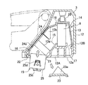
この実施の形態の脱臭装置9によれば、脱臭ハウジング13の上側に脱臭カートリッジ15を装着するための装着口24が設けられる。これにより、洗浄装置1の製造時には、図13に示すように、本体基盤12Aに本体カバー12Bが取り付けられる前に、本体基盤12Aに脱臭ハウジング13を取り付けて支持する。そして、その脱臭ハウジング13の上側から装着口24に脱臭カートリッジ15を落とし込んで挿入することにより、同カートリッジ15が同ハウジング12に装着される。その後、図4に示すように、本体カバー12Bを本体基盤12Aに取り付ければ、脱臭ハウジング13がその装着口24と共に本体カバーに覆われることになる。従って、洗浄装置1の製造時には、本体基盤12Aの下面12aの着脱口21から脱臭カートリッジ15を装着する必要がない。このため、製造時における脱臭装置9の組付作業を簡易なものにすることができる。
【0032】
この実施の形態の脱臭装置9によれば、製造時に、脱臭カートリッジ15を装着口24を通じて装着するとき、同カートリッジ15の摘み片25cと装着口24の凹部24aとの協働により、脱臭ハウジング13に対する脱臭カートリッジ15の装着向きが規定されることになる。即ち、この実施の形態では、脱臭ハウジング13の吸入口16から排出口17へ向かう臭気の流れを許容するために、脱臭カートリッジ15の前面と背面にメッシュ25bが形成されることから、そのメッシュ25bに合わせた向きで同カートリッジ15を同ハウジング13に誤りなく装着する必要がある。従って、製造時には、摘み片25cを凹部24aに整合させる向きで装着口24から脱臭カートリッジ15を挿入することにより、常に脱臭カートリッジ15が所要の向きで正確に脱臭ハウジング13に装着されることになる。このため、脱臭カートリッジ15の装着工程に失敗がなく、装着のやり直しを行う必要がなくなり、脱臭装置9の組付工程の効率化を図ることができるようになる。
【0033】
尚、本発明は前記実施の形態に限定されるものではなく、発明の趣旨を逸脱することのない範囲で構成の一部を適宜に変更して次のように実施することもできる。
【0034】
(1)前記実施の形態では、脱臭カートリッジ15に設けられるフック25dと、脱臭ハウジング13に設けられる段部13aとにより係脱手段を構成したが、その逆に脱臭カートリッジに設けられる段部と、脱臭ハウジングに設けられるフックとにより係脱手段を構成してもよい。その他、凹凸の関係で選択的に係合又は離脱する嵌合構造であれば、係脱手段はフックと段部の組み合わせには限られない。
【0035】
(2)前記実施の形態では、脱臭カートリッジ15に設けられる摘み片25cと、装着口24に設けられる凹部24aとにより向き規定手段を構成したが、脱臭カートリッジに設けられる凹部と、装着口に設けられる凸部とにより向き規定手段を構成してもよい。或いは、脱臭カートリッジの平面形状をその装着向きに合わせた特定形状とし、それに整合した着脱口の開口形状とすることにより向き規定手段を構成してもよい。
【0036】
(3)前記実施の形態では、着脱口21に専用の着脱蓋23を設けたが、着脱蓋23に代わる簡易な止め具を設けたり、着脱蓋23や止め具を省略したりすることもできる。この場合でも、着脱口が本体ハウジングの下面に位置することから、着脱口が人目に触れることがなく、洗浄装置としての見栄えを損ねることがなく、衛生面でも特に問題はないと言える。
【0037】
(4)前記実施の形態では、脱臭ハウジング13の上側に装着口24を設けたが、これを省略することもできる。
【0038】
【発明の効果】
請求項1に記載の発明によれば、通常の使用状態で洗浄装置の見栄えを損ねることがなく、本体ハウジングの表面を常に清潔に保つことができて洗浄装置を衛生的なものにすることができる。
【図面の簡単な説明】
【図1】一実施の形態に係り、人体局部洗浄装置を示す平面図である。
【図2】人体局部洗浄装置を示す側面図である。
【図3】脱臭装置を一部破断して示す平面図である。
【図4】図3のA−A線に沿った断面図である。
【図5】脱臭ハウジングを示す平面図である。
【図6】図5の右側面図である。
【図7】図5の正面図である。
【図8】脱臭カートリッジを示す斜視図である。
【図9】脱臭カートリッジを示す正面図である。
【図10】脱臭カートリッジを示す側面図である。
【図11】脱臭カートリッジを示す平面図である。
【図12】脱臭装置において脱臭カートリッジ交換時を示す断面図である。
【図13】製造時の脱臭カートリッジの装着を示す断面図である。
【図14】従来の脱臭装置を示す断面図である。
【符号の説明】
1 洗浄装置
2 便器
9 脱臭装置
12 本体ハウジング
12a 下面
12A 本体基盤
12B 本体カバー
13 脱臭ハウジング
13a 段部
14 吸入ファン
15 脱臭カートリッジ
16 吸入口
17 排出口
21 着脱口
24 装着口
24a 凹部
25c 摘み片(24a,25cは向き規定手段を構成する。)
25d フック(13a,25dは係脱手段を構成する。)[0001]
BACKGROUND OF THE INVENTION
The present invention relates to a human body local cleaning device that is installed in a toilet and used to clean a human body local part. In detail, it is related with the deodorizing apparatus which deodorizes the odor around a toilet bowl.
[0002]
[Prior art]
The conventional local body cleaning device is a deodorizing device that deodorizes the odor around the toilet in use, in addition to main functions such as cleaning of the human body with a cleaning nozzle, drying with a hot air fan after cleaning, and heating of the toilet seat with a heater. It has a deodorizing function. The purpose of this deodorization is mainly to remove the odor of the user's own defecation and the like, and to remove the odor of another user used immediately before. In recent years, there has been a strong interest in the related industries regarding this type of deodorization, and it is considered useful not only in human body local cleaning devices but also in other home appliances.
[0003]
As a deodorizing device for a human body local cleaning device, a odor component in a toilet room or around a toilet is sucked with a fan and a deodorizer is used to physically and chemically remove odorous components, or ozone is generated by high voltage. There are known methods for decomposing and removing odor components. Among them, the method using a deodorant occupies the mainstream in the current market because the structure is relatively simple and the number of parts is relatively small. This type of deodorant is a consumable item and needs to be replaced with a new one every predetermined period of use. It is done.
[0004]
Japanese Patent Laid-Open No. 5-202548 discloses an example of this type of deodorizing apparatus. As shown in FIG. 14, this deodorizing apparatus is formed into a
Alternatively, as another type, there is a structure in which a charging port is provided on the upper surface or side surface of the main body housing of the human body local cleaning device, and a deodorizing cartridge charged from the charging port is attached to a deodorizing housing provided inside the main body housing. There is also a deodorizing device. In this type of type, a dedicated lid is fitted into the inlet.
[0005]
[Problems to be solved by the invention]
However, in each of the conventional deodorizing devices, the
[0006]
This invention is made | formed in view of the said situation, The objective is to provide the deodorizing apparatus of the hygienic human body local washing | cleaning apparatus, without impairing appearance.
[0007]
[Means for Solving the Problems]
In order to achieve the above object, the invention described in
[0008]
According to the configuration of the above invention, the attachment / detachment port of the deodorization cartridge is provided on the lower side of the deodorization housing, and the attachment / detachment port is opened on the lower surface of the main body housing, so that the main body housing is installed in the toilet bowl. Escapement is not visible to the public. In addition, since the deodorizing cartridge can be mounted from the mounting port provided on the upper side of the deodorizing housing at the time of manufacturing the cleaning apparatus, the assembly work of the deodorizing apparatus at the time of manufacturing can be simplified.
[0009]
In order to achieve the above object, a second aspect of the present invention provides the deodorizing cartridge according to the first aspect of the present invention, wherein the deodorizing cartridge and the deodorizing housing are arranged to selectively engage or disengage the deodorizing cartridge with respect to the deodorizing housing. It is intended that the disengagement means provided in is provided.
[0010]
According to the configuration of the above invention, in addition to the operation of the invention described in
[0011]
In order to achieve the above object, according to a third aspect of the present invention, in the first or second aspect of the present invention, the main body housing covers a main body base including a lower surface and supporting the deodorizing housing, and the deodorizing housing. A main body cover fixed to the main body base, and a mounting opening provided on the upper side of the deodorizing housing for mounting the deodorizing cartridge with the main body cover removed from the main body base. Intended to be
[0012]
According to the configuration of the above invention, in addition to the operation of the first or second aspect, the deodorizing cartridge is attached to the mounting opening from the upper side in a state where the deodorizing housing is supported by the main body base of the main body housing at the time of manufacture. By inserting, the deodorizing cartridge is attached to the deodorizing housing. Thereafter, the main body cover is attached to the main body base, so that the deodorizing housing is covered with the main body cover together with the mounting opening. Therefore, it is not necessary to attach a deodorizing cartridge from the attachment / detachment opening on the lower surface of the main body base during manufacture.
[0013]
In order to achieve the above object, the invention described in
[0014]
According to the configuration of the above invention, in addition to the operation of the invention according to
[0015]
DETAILED DESCRIPTION OF THE INVENTION
Hereinafter, an embodiment in which a deodorizing device for a human body local cleaning device of the present invention is embodied will be described in detail with reference to the drawings.
[0016]
FIG. 1 shows a plan view of a human body local cleaning apparatus (hereinafter simply referred to as “cleaning apparatus”) 1, and FIG. 2 shows a side view of the
[0017]
Next, the
[0018]
The
[0019]
5 is a plan view of the deodorizing
[0020]
As shown in FIGS. 4, 5, and 7, a mounting
[0021]
FIG. 8 is a perspective view of the
[0022]
The front surface of the
[0023]
[0024]
In addition, a
[0025]
As described above, according to the
[0026]
Here, when replacing the
Thereafter, to install a
[0027]
This replacement operation is performed by removing the
[0028]
According to the
[0029]
Here, in the conventional deodorization device, a fastening means such as a screw is used to prevent the exclusive lid from being removed due to excessive force applied during wiping and cleaning to the dedicated lid attached to the attachment / detachment opening on the surface of the main body cover. In some cases, a snap fitting means requiring high accuracy is provided. In this case, extra equipment and time are required to ensure dimensional accuracy during manufacturing, which increases the manufacturing cost of the cleaning device. However, according to the
[0030]
According to the
On the other hand, when a
As described above, the removal operation and the attachment operation of the
[0031]
According to the
[0032]
According to the
[0033]
Note that the present invention is not limited to the above-described embodiment, and may be implemented as follows by appropriately changing a part of the configuration without departing from the spirit of the invention.
[0034]
(1) In the above embodiment, the
[0035]
(2) In the above embodiment, the direction defining means is configured by the
[0036]
(3) In the above-described embodiment, the dedicated attachment /
[0037]
(4) Although the mounting
[0038]
【The invention's effect】
According to the first aspect of the present invention, the surface of the main body housing can always be kept clean without sacrificing the appearance of the cleaning device in a normal use state, and the cleaning device can be made hygienic. it can.
[Brief description of the drawings]
FIG. 1 is a plan view showing a human body local cleaning device according to one embodiment.
FIG. 2 is a side view showing a human body local cleaning device.
FIG. 3 is a plan view showing the deodorizing apparatus with a part broken away.
4 is a cross-sectional view taken along line AA in FIG.
FIG. 5 is a plan view showing a deodorizing housing.
6 is a right side view of FIG. 5. FIG.
7 is a front view of FIG. 5. FIG.
FIG. 8 is a perspective view showing a deodorizing cartridge.
FIG. 9 is a front view showing a deodorizing cartridge.
FIG. 10 is a side view showing a deodorizing cartridge.
FIG. 11 is a plan view showing a deodorizing cartridge.
FIG. 12 is a cross-sectional view showing when the deodorizing cartridge is replaced in the deodorizing apparatus.
FIG. 13 is a cross-sectional view showing mounting of a deodorizing cartridge during production.
FIG. 14 is a cross-sectional view showing a conventional deodorizing apparatus.
[Explanation of symbols]
DESCRIPTION OF
25d hook (13a, 25d constitutes a disengaging means)
Claims (6)
前記本体ハウジングに内蔵され、吸入口及び排出口を含む脱臭ハウジングと、
前記吸入口から臭気を吸入させるために前記脱臭ハウジングに設けられる吸入ファンと、
前記吸入口から吸入された臭気を脱臭するために前記脱臭ハウジングに着脱自在に装着される脱臭カートリッジと、
前記脱臭カートリッジを着脱するために前記脱臭ハウジングの下側に設けられた着脱口と、
前記脱臭カートリッジを装着するために前記脱臭ハウジングの上側に設けられた装着口とを備えること、
前記装着口から前記脱臭カートリッジの装着を行った後、前記装着口が前記本体ハウジングにより塞がれること、
を特徴とする人体局部洗浄装置の脱臭装置。A deodorizing device for a human body local cleaning device having a main body housing installed in a toilet,
A deodorizing housing built in the main body housing and including a suction port and a discharge port;
A suction fan provided in the deodorizing housing for inhaling odor from the suction port;
A deodorizing cartridge that is detachably attached to the deodorizing housing to deodorize the odor sucked from the suction port;
An attachment / detachment opening provided on the lower side of the deodorization housing for attaching / detaching the deodorization cartridge ;
A mounting opening provided on the upper side of the deodorizing housing for mounting the deodorizing cartridge;
After mounting the deodorizing cartridge from the mounting port, the mounting port is blocked by the body housing;
A deodorizing device for a human body local cleaning device.
前記本体基盤から前記本体カバーが取り外された状態で、前記脱臭カートリッジを装着するために前記脱臭ハウジングの上側に設けられた装着口と
を備えたことを特徴とする請求項1乃至請求項3のいずれか一つに記載の人体局部洗浄装置の脱臭装置。The body housing includes a be composed of a body base for supporting the deodorizing housing includes a bottom surface, a body cover that is fixed to the body base covering the deodorizing housing,
The mounting opening provided in the upper side of the said deodorizing housing for mounting | wearing with the said deodorizing cartridge in the state which removed the said main body cover from the said main body base | substrate, The Claim 1 thru | or 3 characterized by the above-mentioned. The deodorizing apparatus for a human body local cleaning apparatus according to any one of the above.
前記脱臭ハウジングの中の所定の部位の内壁に、前記フックと係合する段部が形成され、
前記脱臭カートリッジを前記脱臭ハウジングから取り外す場合には、前記両フックを前記段部から離脱させ、
前記脱臭カートリッジを前記脱臭ハウジングに装着する場合には、前記脱臭カートリッジが前記着脱口を通じて前記脱臭ハウジングの中に挿入されたとき、前記脱臭カートリッジは、前記両フックと前記段部との係合により前記脱臭ハウジングに保持されて装着されることを特徴とする請求項1乃至請求項5のいずれか一つに記載の人体局部洗浄装置の脱臭装置。Hooks having flexibility are formed on the left and right side surfaces of the case of the deodorizing cartridge,
On the inner wall of a predetermined part in the deodorizing housing, a step portion that engages with the hook is formed,
When removing the deodorizing cartridge from the deodorizing housing, the both hooks are detached from the stepped portion,
When the deodorizing cartridge is attached to the deodorizing housing, when the deodorizing cartridge is inserted into the deodorizing housing through the attachment / detachment port, the deodorizing cartridge is engaged with the hooks and the stepped portion. The deodorizing apparatus for a human body local cleaning apparatus according to any one of claims 1 to 5, wherein the deodorizing housing is mounted while being held by the deodorizing housing.
Priority Applications (1)
| Application Number | Priority Date | Filing Date | Title |
|---|---|---|---|
| JP2001046842A JP4626065B2 (en) | 2001-02-22 | 2001-02-22 | Deodorizing device for local body cleaning equipment |
Applications Claiming Priority (1)
| Application Number | Priority Date | Filing Date | Title |
|---|---|---|---|
| JP2001046842A JP4626065B2 (en) | 2001-02-22 | 2001-02-22 | Deodorizing device for local body cleaning equipment |
Publications (3)
| Publication Number | Publication Date |
|---|---|
| JP2002242258A JP2002242258A (en) | 2002-08-28 |
| JP2002242258A5 JP2002242258A5 (en) | 2010-04-15 |
| JP4626065B2 true JP4626065B2 (en) | 2011-02-02 |
Family
ID=18908387
Family Applications (1)
| Application Number | Title | Priority Date | Filing Date |
|---|---|---|---|
| JP2001046842A Expired - Fee Related JP4626065B2 (en) | 2001-02-22 | 2001-02-22 | Deodorizing device for local body cleaning equipment |
Country Status (1)
| Country | Link |
|---|---|
| JP (1) | JP4626065B2 (en) |
Citations (3)
| Publication number | Priority date | Publication date | Assignee | Title |
|---|---|---|---|---|
| JPH0710079U (en) * | 1993-07-13 | 1995-02-10 | 株式会社イナックス | Toilet deodorizer |
| JPH0731979U (en) * | 1993-11-18 | 1995-06-16 | 株式会社イナックス | Deodorant cartridge |
| JPH11253361A (en) * | 1998-03-12 | 1999-09-21 | Hitachi Chem Co Ltd | Toilet seat device with deodorization |
-
2001
- 2001-02-22 JP JP2001046842A patent/JP4626065B2/en not_active Expired - Fee Related
Patent Citations (3)
| Publication number | Priority date | Publication date | Assignee | Title |
|---|---|---|---|---|
| JPH0710079U (en) * | 1993-07-13 | 1995-02-10 | 株式会社イナックス | Toilet deodorizer |
| JPH0731979U (en) * | 1993-11-18 | 1995-06-16 | 株式会社イナックス | Deodorant cartridge |
| JPH11253361A (en) * | 1998-03-12 | 1999-09-21 | Hitachi Chem Co Ltd | Toilet seat device with deodorization |
Also Published As
| Publication number | Publication date |
|---|---|
| JP2002242258A (en) | 2002-08-28 |
Similar Documents
| Publication | Publication Date | Title |
|---|---|---|
| JP6515461B2 (en) | Sanitary cleaning device | |
| EP1985216B1 (en) | Vacuum cleaner having apparatus for giving off fragrant odor | |
| JP2006022977A (en) | Air cleaner | |
| JP2004184061A (en) | Cooker with air cleaner | |
| JP6769168B2 (en) | Toilet seat device | |
| JP4626065B2 (en) | Deodorizing device for local body cleaning equipment | |
| RU2414165C2 (en) | Fastening device for vacuum cleaner napkin and method of its manufacturing | |
| JP2005320715A (en) | Closet seat device washing douche with warm water | |
| JP6704528B2 (en) | Hand dryer | |
| KR20100079263A (en) | Bidet for toilet stool | |
| KR20070011220A (en) | Device for removing stink for toilet bowl | |
| TWI676455B (en) | Hand dryer | |
| JP2006090022A (en) | Warm-water cleaning toilet seat unit | |
| JP6424512B2 (en) | Sanitary cleaning device | |
| KR101012995B1 (en) | Humidifier combined an air cleaner | |
| KR101076976B1 (en) | Air cleaner | |
| JP2604183Y2 (en) | Deodorizing mechanism | |
| KR101076933B1 (en) | Air cleaner | |
| KR200320422Y1 (en) | Structure for fixing filter and inhalation grill for inner machine of air conditioner | |
| KR100564492B1 (en) | Installing structure of filter-assembly for air cleaner | |
| JP6487297B2 (en) | Deodorizing device and toilet | |
| JP2003213762A (en) | Toilet apparatus | |
| TW201912091A (en) | Hand drying device | |
| JP2023068371A (en) | toilet seat device | |
| KR20220070622A (en) | The discharge of odour from the toilet with multiple inlet |
Legal Events
| Date | Code | Title | Description |
|---|---|---|---|
| A621 | Written request for application examination |
Free format text: JAPANESE INTERMEDIATE CODE: A621 Effective date: 20080121 |
|
| A521 | Written amendment |
Free format text: JAPANESE INTERMEDIATE CODE: A523 Effective date: 20100225 |
|
| A977 | Report on retrieval |
Free format text: JAPANESE INTERMEDIATE CODE: A971007 Effective date: 20100804 |
|
| A131 | Notification of reasons for refusal |
Free format text: JAPANESE INTERMEDIATE CODE: A131 Effective date: 20100817 |
|
| A521 | Written amendment |
Free format text: JAPANESE INTERMEDIATE CODE: A523 Effective date: 20100916 |
|
| TRDD | Decision of grant or rejection written | ||
| A01 | Written decision to grant a patent or to grant a registration (utility model) |
Free format text: JAPANESE INTERMEDIATE CODE: A01 Effective date: 20101012 |
|
| A01 | Written decision to grant a patent or to grant a registration (utility model) |
Free format text: JAPANESE INTERMEDIATE CODE: A01 |
|
| A61 | First payment of annual fees (during grant procedure) |
Free format text: JAPANESE INTERMEDIATE CODE: A61 Effective date: 20101025 |
|
| FPAY | Renewal fee payment (event date is renewal date of database) |
Free format text: PAYMENT UNTIL: 20131119 Year of fee payment: 3 |
|
| R151 | Written notification of patent or utility model registration |
Ref document number: 4626065 Country of ref document: JP Free format text: JAPANESE INTERMEDIATE CODE: R151 |
|
| FPAY | Renewal fee payment (event date is renewal date of database) |
Free format text: PAYMENT UNTIL: 20131119 Year of fee payment: 3 |
|
| LAPS | Cancellation because of no payment of annual fees |