JP4625632B2 - Vehicle drive device - Google Patents
Vehicle drive device Download PDFInfo
- Publication number
- JP4625632B2 JP4625632B2 JP2003430149A JP2003430149A JP4625632B2 JP 4625632 B2 JP4625632 B2 JP 4625632B2 JP 2003430149 A JP2003430149 A JP 2003430149A JP 2003430149 A JP2003430149 A JP 2003430149A JP 4625632 B2 JP4625632 B2 JP 4625632B2
- Authority
- JP
- Japan
- Prior art keywords
- slip
- torque
- rear wheel
- motor
- driving
- Prior art date
- Legal status (The legal status is an assumption and is not a legal conclusion. Google has not performed a legal analysis and makes no representation as to the accuracy of the status listed.)
- Expired - Fee Related
Links
- 238000001514 detection method Methods 0.000 claims description 22
- 230000002829 reductive effect Effects 0.000 claims description 22
- 238000010248 power generation Methods 0.000 claims description 10
- 230000007423 decrease Effects 0.000 claims description 9
- 230000003247 decreasing effect Effects 0.000 claims description 9
- 238000002485 combustion reaction Methods 0.000 claims description 8
- 238000010586 diagram Methods 0.000 description 13
- 230000001133 acceleration Effects 0.000 description 11
- 238000000034 method Methods 0.000 description 10
- 230000005540 biological transmission Effects 0.000 description 7
- 230000000670 limiting effect Effects 0.000 description 2
- 230000003313 weakening effect Effects 0.000 description 2
- 230000002441 reversible effect Effects 0.000 description 1
- 230000035945 sensitivity Effects 0.000 description 1
- 230000003068 static effect Effects 0.000 description 1
- 238000004804 winding Methods 0.000 description 1
Images


Classifications
-
- B—PERFORMING OPERATIONS; TRANSPORTING
- B60—VEHICLES IN GENERAL
- B60W—CONJOINT CONTROL OF VEHICLE SUB-UNITS OF DIFFERENT TYPE OR DIFFERENT FUNCTION; CONTROL SYSTEMS SPECIALLY ADAPTED FOR HYBRID VEHICLES; ROAD VEHICLE DRIVE CONTROL SYSTEMS FOR PURPOSES NOT RELATED TO THE CONTROL OF A PARTICULAR SUB-UNIT
- B60W10/00—Conjoint control of vehicle sub-units of different type or different function
- B60W10/04—Conjoint control of vehicle sub-units of different type or different function including control of propulsion units
- B60W10/08—Conjoint control of vehicle sub-units of different type or different function including control of propulsion units including control of electric propulsion units, e.g. motors or generators
-
- B—PERFORMING OPERATIONS; TRANSPORTING
- B60—VEHICLES IN GENERAL
- B60K—ARRANGEMENT OR MOUNTING OF PROPULSION UNITS OR OF TRANSMISSIONS IN VEHICLES; ARRANGEMENT OR MOUNTING OF PLURAL DIVERSE PRIME-MOVERS IN VEHICLES; AUXILIARY DRIVES FOR VEHICLES; INSTRUMENTATION OR DASHBOARDS FOR VEHICLES; ARRANGEMENTS IN CONNECTION WITH COOLING, AIR INTAKE, GAS EXHAUST OR FUEL SUPPLY OF PROPULSION UNITS IN VEHICLES
- B60K6/00—Arrangement or mounting of plural diverse prime-movers for mutual or common propulsion, e.g. hybrid propulsion systems comprising electric motors and internal combustion engines ; Control systems therefor, i.e. systems controlling two or more prime movers, or controlling one of these prime movers and any of the transmission, drive or drive units Informative references: mechanical gearings with secondary electric drive F16H3/72; arrangements for handling mechanical energy structurally associated with the dynamo-electric machine H02K7/00; machines comprising structurally interrelated motor and generator parts H02K51/00; dynamo-electric machines not otherwise provided for in H02K see H02K99/00
- B60K6/20—Arrangement or mounting of plural diverse prime-movers for mutual or common propulsion, e.g. hybrid propulsion systems comprising electric motors and internal combustion engines ; Control systems therefor, i.e. systems controlling two or more prime movers, or controlling one of these prime movers and any of the transmission, drive or drive units Informative references: mechanical gearings with secondary electric drive F16H3/72; arrangements for handling mechanical energy structurally associated with the dynamo-electric machine H02K7/00; machines comprising structurally interrelated motor and generator parts H02K51/00; dynamo-electric machines not otherwise provided for in H02K see H02K99/00 the prime-movers consisting of electric motors and internal combustion engines, e.g. HEVs
- B60K6/50—Architecture of the driveline characterised by arrangement or kind of transmission units
- B60K6/52—Driving a plurality of drive axles, e.g. four-wheel drive
-
- B—PERFORMING OPERATIONS; TRANSPORTING
- B60—VEHICLES IN GENERAL
- B60W—CONJOINT CONTROL OF VEHICLE SUB-UNITS OF DIFFERENT TYPE OR DIFFERENT FUNCTION; CONTROL SYSTEMS SPECIALLY ADAPTED FOR HYBRID VEHICLES; ROAD VEHICLE DRIVE CONTROL SYSTEMS FOR PURPOSES NOT RELATED TO THE CONTROL OF A PARTICULAR SUB-UNIT
- B60W30/00—Purposes of road vehicle drive control systems not related to the control of a particular sub-unit, e.g. of systems using conjoint control of vehicle sub-units
- B60W30/18—Propelling the vehicle
- B60W30/18172—Preventing, or responsive to skidding of wheels
-
- B—PERFORMING OPERATIONS; TRANSPORTING
- B60—VEHICLES IN GENERAL
- B60W—CONJOINT CONTROL OF VEHICLE SUB-UNITS OF DIFFERENT TYPE OR DIFFERENT FUNCTION; CONTROL SYSTEMS SPECIALLY ADAPTED FOR HYBRID VEHICLES; ROAD VEHICLE DRIVE CONTROL SYSTEMS FOR PURPOSES NOT RELATED TO THE CONTROL OF A PARTICULAR SUB-UNIT
- B60W2520/00—Input parameters relating to overall vehicle dynamics
- B60W2520/26—Wheel slip
-
- B—PERFORMING OPERATIONS; TRANSPORTING
- B60—VEHICLES IN GENERAL
- B60W—CONJOINT CONTROL OF VEHICLE SUB-UNITS OF DIFFERENT TYPE OR DIFFERENT FUNCTION; CONTROL SYSTEMS SPECIALLY ADAPTED FOR HYBRID VEHICLES; ROAD VEHICLE DRIVE CONTROL SYSTEMS FOR PURPOSES NOT RELATED TO THE CONTROL OF A PARTICULAR SUB-UNIT
- B60W2520/00—Input parameters relating to overall vehicle dynamics
- B60W2520/28—Wheel speed
-
- Y—GENERAL TAGGING OF NEW TECHNOLOGICAL DEVELOPMENTS; GENERAL TAGGING OF CROSS-SECTIONAL TECHNOLOGIES SPANNING OVER SEVERAL SECTIONS OF THE IPC; TECHNICAL SUBJECTS COVERED BY FORMER USPC CROSS-REFERENCE ART COLLECTIONS [XRACs] AND DIGESTS
- Y02—TECHNOLOGIES OR APPLICATIONS FOR MITIGATION OR ADAPTATION AGAINST CLIMATE CHANGE
- Y02T—CLIMATE CHANGE MITIGATION TECHNOLOGIES RELATED TO TRANSPORTATION
- Y02T10/00—Road transport of goods or passengers
- Y02T10/60—Other road transportation technologies with climate change mitigation effect
- Y02T10/62—Hybrid vehicles
-
- Y—GENERAL TAGGING OF NEW TECHNOLOGICAL DEVELOPMENTS; GENERAL TAGGING OF CROSS-SECTIONAL TECHNOLOGIES SPANNING OVER SEVERAL SECTIONS OF THE IPC; TECHNICAL SUBJECTS COVERED BY FORMER USPC CROSS-REFERENCE ART COLLECTIONS [XRACs] AND DIGESTS
- Y02—TECHNOLOGIES OR APPLICATIONS FOR MITIGATION OR ADAPTATION AGAINST CLIMATE CHANGE
- Y02T—CLIMATE CHANGE MITIGATION TECHNOLOGIES RELATED TO TRANSPORTATION
- Y02T10/00—Road transport of goods or passengers
- Y02T10/60—Other road transportation technologies with climate change mitigation effect
- Y02T10/72—Electric energy management in electromobility
Landscapes
- Engineering & Computer Science (AREA)
- Transportation (AREA)
- Mechanical Engineering (AREA)
- Chemical & Material Sciences (AREA)
- Combustion & Propulsion (AREA)
- Automation & Control Theory (AREA)
- Arrangement And Driving Of Transmission Devices (AREA)
- Electric Propulsion And Braking For Vehicles (AREA)
- Hybrid Electric Vehicles (AREA)
Description
本発明は、車両の4輪を駆動する車両駆動装置に係り、特に、スリップ時の制御に好適な車両駆動装置に関する。
The present invention relates to a vehicle drive device that drives four wheels of a vehicle , and more particularly to a vehicle drive device suitable for control during a slip.
従来の車両の4輪駆動装置としては、たとえば、特開2002−67723号公報に記載されているように、スリップを検出した際、このスリップしている駆動輪のトルクを小さくすることにより、スリップを回避するものが知られている。 As a conventional four-wheel drive device for a vehicle, for example, as described in Japanese Patent Application Laid-Open No. 2002-67723, when slip is detected, the slipping drive wheel torque is reduced to reduce slip. What is known to avoid this is known.
しかしながら、特開2002−67723号公報に記載のものでは、動摩擦係数が静摩擦係数より小さい点について配慮がされておらず、スリップを検出した際、該スリップを検出した駆動輪のトルクを小さくすると駆動力が不足し走破性能が悪化するという問題があった。 However, in the thing of Unexamined-Japanese-Patent No. 2002-67723, consideration is not given about the point that a dynamic friction coefficient is smaller than a static friction coefficient, and it will drive if the torque of the driving wheel which detected this slip is made small when a slip is detected. There was a problem that running performance deteriorated due to lack of power.
本発明の目的は、スリップ時の駆動トルクが不足することを抑制して、走破性能の向上した4輪駆動装置を提供することにある。 An object of the present invention is to provide a four-wheel drive device that has improved running performance while suppressing a shortage of drive torque during a slip.
(1)上記目的を達成するために、本発明は、4つの車輪を駆動して走行する車両に搭載された駆動装置であって、前記4つの車輪のうち、内燃機関によって駆動される前輪とは異なる後輪を駆動する電動機と、前記内燃機関によって駆動され、前記電動機の電機子コイルに駆動用電力を供給する発電機と、前記前輪のスリップ及び前記後輪のスリップを検出するためのスリップ検出手段と、該スリップ検出手段により前記前輪のスリップが検出されて、前輪速と後輪速との差に基づいて算出した前記前輪のスリップ状態を収束させるための駆動トルクを前記電動機から前記後輪に供給しているときに、前記スリップ検出手段により前記後輪のスリップが検出された場合には、前記電動機から前記後輪に供給される駆動トルクを、前記後輪のスリップが収束する予め算出した駆動トルクまで減少させてから増加させるように、前記駆動トルクを補正すると共に、それでも前記スリップ検出手段により前記後輪のスリップが繰り返し検出される場合には、前記後輪のスリップが繰り返し検出される路面状態にある間、前記電動機から前記後輪に供給される駆動トルクを、前記後輪のスリップが収束する予め算出した駆動トルクまで減少させてから増加させる、という動作が繰り返されるように、前記駆動トルクを補正するトルク補正手段と、を有し、前記トルク補正手段は、前記スリップの回数に対応する駆動トルク制限値を備え、前記増加させる駆動トルクを、前記スリップの回数に応じて、前記スリップの回数が増加するほど駆動トルク制限値が小さくなるように、前記スリップの回数に対応する駆動トルク制限値まで増加させる、ようにしたものである。
かかる構成により、スリップ時の駆動トルクが不足することを抑制して、走破性能の向上し得るものとなる。
(1) In order to achieve the above object, the present invention is a drive device mounted on a vehicle that travels by driving four wheels, and includes a front wheel driven by an internal combustion engine among the four wheels. Includes a motor for driving different rear wheels, a generator that is driven by the internal combustion engine and supplies driving power to an armature coil of the motor, and a slip for detecting a slip of the front wheel and a slip of the rear wheel Detection means, and slip detection of the front wheel detected by the slip detection means, and driving torque for converging the slip condition of the front wheel calculated based on a difference between the front wheel speed and the rear wheel speed is transmitted from the motor to the rear. If slip of the rear wheel is detected by the slip detection means while supplying to the wheel, the driving torque supplied from the electric motor to the rear wheel is When the driving torque is corrected so that the lip converges to a previously calculated driving torque and then increased, the slip detection means repeatedly detects the slip of the rear wheel. The driving torque supplied from the electric motor to the rear wheel is reduced to a pre-calculated driving torque that converges the rear wheel slip while the road surface condition is repeatedly detected. And a torque correction means for correcting the drive torque, the torque correction means having a drive torque limit value corresponding to the number of slips, and increasing the drive torque to the slip. In accordance with the number of slips, the slip limit value decreases as the number of slips increases. Increased to the drive torque limit value corresponding to the number of times, it is obtained by way.
With such a configuration, it is possible to improve the running performance by suppressing the drive torque at the time of slipping from being insufficient.
(2)上記(1)において、好ましくは、前記トルク補正手段は、前記減少させた駆動トルクを所定時間、保持した後、前記駆動トルクを増加させるものである。
In (2) above (1), preferably, the torque correcting means for a predetermined time the drive torque which the reduced, after holding, in which increasing the driving torque.
(3)また、上記目的を達成するために、本発明は、4つの車輪を駆動して走行する車両に搭載された駆動装置であって、前記4つの車輪のうち、内燃機関によって駆動される前輪とは異なる後輪を駆動する電動機と、前記内燃機関によって駆動され、前記電動機の電機子コイルに駆動用電力を供給する発電機と、前記発電機の発電を制御して前記駆動用電力を制御し、前記電動機の駆動を制御する制御装置と、を有し、前記前輪にスリップが発生したとき、前輪速と後輪速との差に基づいて算出した前記前輪のスリップ状態を収束させるための駆動トルクが前記電動機から前記後輪に供給しているときに、前記後輪にスリップが発生した場合には、前記電動機から前記後輪に供給される駆動トルクを、前記後輪のスリップが収束する予め算出した駆動トルクまで減少させてから増加させるように、前記駆動トルクを補正すると共に、それでも前記スリップ検出手段により前記後輪のスリップが繰り返し検出される場合には、前記スリップが繰り返し発生する路面状態にある間、前記電動機から前記後輪に伝達される駆動トルクが、前記スリップを収束する予め算出した駆動トルクに減少してから増加する、という動作が繰り返されるように、前記制御装置から前記発電機に出力される発電指令を増減させ、前記制御装置は、前記スリップの回数に対応する駆動トルク制限値を備え、前記増加させる駆動トルクを、前記スリップの回数に応じて、前記スリップの回数が増加するほど駆動トルク制限値が小さくなるように、前記スリップの回数に対応する駆動トルク制限値まで増加させるようにしたものである。
かかる構成により、スリップ時の駆動トルクが不足することを抑制して、走破性能の向上し得るものとなる。
(4)上記(3)において、好ましくは、前記減少させた駆動トルクが所定時間、保持された後、前記駆動トルクが増加するように、前記減少させた発電指令を所定時間、保持した後、増加させるものである。
( 3 ) In order to achieve the above object, the present invention is a drive device mounted on a vehicle that travels by driving four wheels, and is driven by an internal combustion engine among the four wheels. An electric motor that drives a rear wheel different from the front wheels, a generator that is driven by the internal combustion engine and supplies driving power to an armature coil of the motor, and controls the power generation of the generator to generate the driving power. And a control device for controlling the driving of the electric motor, and when the front wheel slips, to converge the slip state of the front wheel calculated based on the difference between the front wheel speed and the rear wheel speed When a slip occurs in the rear wheel when the drive torque is supplied from the electric motor to the rear wheel, the drive torque supplied from the electric motor to the rear wheel is set to the slip of the rear wheel. Pre-converge So as to increase from the reduced to the drive torque that issued, as well as correcting the drive torque, still in the case where the slip of the rear wheel is repeatedly detected by the slip detecting means, a road surface state in which the slip repeatedly occurs The control device causes the power generation to be repeated so that the drive torque transmitted from the electric motor to the rear wheel is reduced to a pre-calculated drive torque that converges the slip and then increased. The power generation command output to the machine is increased or decreased , and the control device has a drive torque limit value corresponding to the number of slips, and the drive torque to be increased is determined according to the number of slips. The drive torque limit value is increased to the drive torque limit value corresponding to the number of slips so that the drive torque limit value decreases as the value increases. It was made to let you.
With such a configuration, it is possible to improve the running performance by suppressing the drive torque at the time of slipping from being insufficient.
( 4 ) In the above ( 3 ), preferably, after the reduced drive torque is held for a predetermined time, and then the reduced power generation command is held for a predetermined time so that the drive torque increases, Ru increase is also of the.
本発明によれば、4輪駆動装置におけるスリップ時の駆動トルクが不足することを抑制して、走破性能の向上することができる。 ADVANTAGE OF THE INVENTION According to this invention, it can suppress that the drive torque at the time of a slip in a 4-wheel drive device is insufficient, and can improve driving performance.
以下、図1〜図11を用いて、本発明の一実施形態による4輪駆動装置の構成及び動作について説明する。
最初に、図1を用いて、本実施形態による4輪駆動装置を用いる4輪駆動車両の全体構成について説明する。
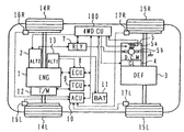
図1は、本発明の一実施形態による4輪駆動装置を用いる4輪駆動車両の全体構成を示すシステムブロック図である。
4輪駆動車両は、エンジン1及び直流電動機5を備えている。エンジン1の駆動力は、トランスミッション12及び第1の車軸を介して、左右の前輪14R,14Lに伝達され、前輪14R,14Lを駆動する。
Hereinafter, the configuration and operation of a four-wheel drive device according to an embodiment of the present invention will be described with reference to FIGS.
First, the overall configuration of a four-wheel drive vehicle using the four-wheel drive device according to the present embodiment will be described with reference to FIG.
FIG. 1 is a system block diagram showing an overall configuration of a four-wheel drive vehicle using a four-wheel drive device according to an embodiment of the present invention.
The four-wheel drive vehicle includes an
直流電動機5の駆動力は、クラッチ4,デファレンシャルギヤ3及び第2の車軸を介して、左右の後輪15R,15Lに伝達され、後輪15R,15Lを駆動する。デファレンシャルギヤ3とクラッチ4が連結されると、直流電動機5の回転力は、クラッチ4,デファレンシャルギヤ3を介して後輪軸に伝えられ、後輪15R,15Lを駆動する。クラッチ4が外れると、直流電動機5は後輪15R,15L側から機械的に切り離され、後輪15R,15Lは駆動力を路面に伝えないものである。クラッチ4の締結・開放は、4輪駆動コントロールユニット(4WDCU)100によって制御される。なお、直流電動機5は、例えば、正転逆転の切替えが容易な直流分巻電動機、または他励直流電動機を用いている。
なお、以上の説明では、前輪14R,14Lをエンジン1で駆動し、後輪15R,15Lを直流電動機5で駆動する4輪駆動車両として説明しているが、前輪を直流電動機で駆動し、後輪をエンジンで駆動するようにしてもよいものである。また、直流電動機を用いず前輪と後輪の駆動力調整手段を有し、プロペラシャフトにて接続させるメカ式4輪駆動車としても良いものである。
エンジンルーム内には、通常の充電発電システムを行う補機用発電機(ALT1)13及び補機バッテリー11が配置される。補機用発電機13は、エンジン1によってベルト駆動され、その出力は補機バッテリー11に蓄積される。
The driving force of the
In the above description, the
In the engine room, an auxiliary generator (ALT1) 13 and an auxiliary battery 11 that perform a normal charging power generation system are arranged. The
また、補機用発電機13の近傍には、駆動用高出力発電機(ALT2)2が配設されている。駆動用高出力発電機(ALT2)2は、エンジン1によりベルト駆動され、その出力によって直流電動機5が駆動される。駆動用高出力発電機(ALT2)2の発電電圧は、4WDCU100によって制御される。駆動用高出力発電機(ALT2)2の発電電力が変化すると、直流電動機5の出力である直流電動機トルクが変化する。すなわち、4WDCU100は、駆動用高出力発電機(ALT2)2に対して出力の指令値(発電機(オルタネータ)の界磁電流値が所定値となるようなデューティ信号)を出力することにより、駆動用高出力発電機(ALT2)2の発電電力が変化する。駆動用高出力発電機(ALT2)2の発電電圧は、直流電動機5の電機子コイル5bに印加され、直流電動機5の出力(直流電動機トルク)が変化する。4WDCU100は、高出力発電機2の出力(発電電力)を制御することにより、直流電動機5の出力(直流電動機トルク)を制御する。さらに、直流電動機5が高回転となる領域では、4WDCU100は、直流電動機5の界磁巻線5aに流す界磁電流を弱め界磁制御することにより、直流電動機5を直接制御して、直流電動機5が高速回転可能となるように制御する。
エンジン1の出力は、エンジンコントロールユニット(ECU)8からの指令により駆動される電子制御スロットルにより制御される。電子制御スロットルには、アクセル開度センサ(図示せず)が設けられており、アクセル開度を検出する。なお、電子制御スロットルの代わりにメカリンクのアクセルペダル及びスロットルを用いる場合には、アクセルペダルにアクセル開度センサを設けることができる。また、トランスミッションコントローラ(TCU)9は、トランスミッション12を制御する。アクセル開度センサの出力は、4WDCU100に取り込まれる、
前輪14R,14L及び後輪15R,15Lの各車輪には、回転速度を検出する車輪速センサ16R,16L,17R,17Lが設けられている。また、ブレーキには、アンチロックブレーキコントロールユニット(ACU)10によって制御されるアンチロックブレーキアクチュエータが設けられている。
各信号線は、エンジンコントロールユニット(ECU)8又は、トランスミッションコントロールユニット(TCU)9又は他の制御ユニットのインターフェイスから車内LAN(CAN)バス経由で4WDコントロールユニット(4WDCU)100に入手するようにしてもよいものである。
高出力発電機2と直流電動機5の間には、大容量リレー(RLY)7が設けられ高出力発電機2の出力を遮断できる構成とする。リレー7の開閉は、4WDCU100によって制御される。
Further, in the vicinity of the
The output of the
Each signal line is obtained from the interface of the engine control unit (ECU) 8, the transmission control unit (TCU) 9, or another control unit to the 4WD control unit (4WDCU) 100 via the in-vehicle LAN (CAN) bus. Is also good.
A large-capacity relay (RLY) 7 is provided between the high-
次に、図2を用いて、本実施形態による4輪駆動装置の構成について説明する。
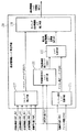
図2は、本発明の一実施形態による4輪駆動装置の構成を示すシステムブロック図である。
Next, the configuration of the four-wheel drive device according to the present embodiment will be described with reference to FIG.
FIG. 2 is a system block diagram showing the configuration of the four-wheel drive device according to one embodiment of the present invention.
4WDCU100は、モード判定手段110と、直流電動機トルク算出手段130と、ドライバ手段150とを備えている。4WDCU100には、入力信号として、車輪速(VW)信号と、アクセル開度(TVO)信号と、シフト位置信号と、電流(Ia)信号と、電流(If)信号と、直流電動機回転数(Nm)信号が入力する。
The 4WDCU 100 includes a
車輪速(VW)信号は、車輪速センサ16R,16L,17R,17Lによってそれぞれ検出された右前輪車輪速VWF_RHと、左前輪車輪速VWF_LHと、右後輪車輪速VWR_RHと、左後輪車輪速VWR_LHとからなる。なお、4WDCU100は、内部において、右後輪車輪速VWR_RHと左後輪車輪速VWR_LHとから平均値である後輪平均速VWRを算出する。
The wheel speed (VW) signals are the right front wheel speed VWF_RH, the left front wheel speed VWF_LH, the right rear wheel speed VWR_RH, and the left rear wheel speed detected by the
アクセル開度(TVO)信号は、前述したアクセル開度センサの出力が入力する。4WDCU100は、アクセル開度(TVO)信号がアクセル開度2%となると、アクセルオン信号を生成し、2%以下になるとアクセルオフ信号を生成する。なお、アクセルオンと判断するときのしきい値を3%として、アクセルオフと判断するときのしきい値を1%として、オンオフ判定のしきい値にヒステリシス特性をもたせることも可能である。
The accelerator opening (TVO) signal is input from the output of the accelerator opening sensor described above. The
シフト位置信号は、シフトレバーの近傍に備えられたシフトポジションセンサの出力が入力する。ここでは、シフト位置がDレンジにあるか、他のレンジになっているかの信号が入力する。 The output of the shift position sensor provided near the shift lever is input as the shift position signal. Here, a signal indicating whether the shift position is in the D range or another range is input.
電流(Ia)信号は、駆動用高出力発電機(ALT2)2の出力電流であり直流電動機の電機子コイル5bに流れる電流である。電流(If)信号は、直流電動機5の界磁コイルに流れる界磁電流である。直流電動機回転数(Nm)信号は、直流電動機5の回転数を示す信号である。
The current (Ia) signal is an output current of the driving high output generator (ALT2) 2 and is a current flowing through the armature coil 5b of the DC motor. The current (If) signal is a field current flowing through the field coil of the
また、4WDCU100は、駆動用高出力発電機(ALT2)2の界磁コイルに流れる界磁電流を制御するためのALT界磁電流制御信号と、直流電動機5の界磁コイルに流れる界磁電流を制御するための直流電動機界磁電流制御信号と、リレー7の開閉を制御するRLY駆動信号と、クラッチ4の締結・開放を制御するクラッチ制御信号とを出力する。
The
モード判定手段110は、車輪速(VW)信号と、アクセル開度(TVO)信号と、シフト位置信号とに基づいて、4輪駆動のモードを判定する。判定されたモードとしては、I)4WD待機モードと、II)クリープモードと、III)4WD制御モードと、IV)回転合わせモードと、V)停止シーケンスモードがある。
The
ここで、図3も参照して、本実施形態による4輪駆動装置の中のモード判定手段110の動作について説明する。
図3は、本発明の一実施形態による4輪駆動装置の中のモード判定手段の動作を示すタイミングチャートである。
Here, the operation of the
FIG. 3 is a timing chart showing the operation of the mode determination means in the four-wheel drive device according to the embodiment of the present invention.
図3において、図3(A)は路面状態を示している。例えば、路面の摩擦係数の大きなドライ路と、摩擦係数の小さな低μ路を示している。図3(B)は、アクセル開度を示している。前述したように、アクセル開度(TVO)信号に応じて、アクセル開度2%となるとアクセルオンとなり、2%以下になるとアクセルオフとなる。図3(C)は、直流電動機トルク(Nm)を示している。図3(D)は、シフト位置を示している。シフトポジションセンサの出力により、シフト位置がDレンジにあるか、他のレンジを区別している。図3(E)は、車輪速VWを示している。車輪速(VW)信号は、右前輪車輪速VWF_RHと、左前輪車輪速VWF_Lと、右後輪車輪速VWR_RHと、左後輪車輪速VWR_LHとからなるが、ここでは必要なものを図示している。図3(F)は、モード判定手段110によって判定されたモードを示している。
In FIG. 3, FIG. 3 (A) shows the road surface state. For example, a dry road having a large friction coefficient on the road surface and a low μ road having a small friction coefficient are shown. FIG. 3B shows the accelerator opening. As described above, according to the accelerator opening (TVO) signal, the accelerator is turned on when the accelerator opening is 2%, and the accelerator is turned off when the accelerator opening is 2% or less. FIG. 3C shows the DC motor torque (Nm). FIG. 3D shows the shift position. Depending on the output of the shift position sensor, the shift position is in the D range or other ranges are distinguished. FIG. 3E shows the wheel speed VW. The wheel speed (VW) signal consists of a right front wheel speed VWF_RH, a left front wheel speed VWF_L, a right rear wheel speed VWR_RH, and a left rear wheel speed VWR_LH. Yes. FIG. 3F shows the mode determined by the
図3(B)に示すようにアクセル開度がオフで、図3(D)に示すようにシフト位置がDレンジであり、図3(E)に示すように車輪速VWが0km/hのとき、モード判定手段110は、I)4WD待機モードと判定する。そして、モード判定手段110は、図2に示したドライバ手段150に対して、目標直流電動機トルクとして、例えば、0.5Nmを出力する。直流電動機5の出力トルクを、例えば0.5Nmとして、直流電動機5からわずかに、駆動トルクを後輪に伝えておくことにより、次に4輪駆動となった際に直ちに応答できるように待機する。ドライバ手段150は、目標直流電動機トルクが、例えば0.5Nmとなるように、ALT界磁電流制御信号を出力するが、ドライバ手段150の詳細については、図7を用いて後述する。
The accelerator opening is off as shown in FIG. 3 (B), the shift position is in the D range as shown in FIG. 3 (D), and the wheel speed VW is 0 km / h as shown in FIG. 3 (E). At this time, the mode determination means 110 determines that I) 4WD standby mode. Then, the
次に、図3(B)に示すようにアクセル開度がオフで、図3(D)に示すようにシフト位置がDレンジであり、図3(E)に示すように車輪速VWが0km/hよりわずかに大きくなり、車両がクリープ状態になると、モード判定手段110は、II)クリープモードと判定する。そして、モード判定手段110は、図2に示したドライバ手段150に対して、目標直流電動機トルクとして、I)4WD待機モード時よりは大きな、例えば、1.0Nmを出力する。すなわち、エンジン1によって前輪に駆動力が伝達され、車両がクリープ状態になったときは、後輪に対しても直流電動機5から駆動力を伝達して、前後輪の駆動によるでクリープ状態とする。
Next, the accelerator opening is off as shown in FIG. 3B, the shift position is in the D range as shown in FIG. 3D, and the wheel speed VW is 0 km as shown in FIG. 3E. When the vehicle is slightly larger than / h and the vehicle is in a creep state, the mode determination means 110 determines that the mode is II) creep mode. Then, the mode determination means 110 outputs, for example, 1.0 Nm, which is larger than that in the 4WD standby mode, as the target DC motor torque, to the driver means 150 shown in FIG. That is, when the driving force is transmitted to the front wheels by the
次に、図3(B)に示すようにアクセル開度がオンとなり、図3(D)に示すようにシフト位置がDレンジになると、モード判定手段110は、III)4WD制御モードと判定する。そして、モード判定手段110は、図2に示した直流電動機トルク算出手段130に対して、III)4WD制御モードであることを通知する。直流電動機トルク算出手段130は、図3(C)に示すように、目標直流電動機トルクを、例えば、4.5Nmとする。そして、図3(E)に示す車輪速(VW)が5km/hになるまで、目標直流電動機トルクを4.5Nmに維持する。車輪速(VW)が5km/hになると、その後、所定時間T2の後目標トルクが0.5Nmとなるように、目標直流電動機トルクを直線的に減少させる。図3(C)に示す目標トルクが0.5Nmとなると、モード判定手段110は、V)停止シーケンスモードと判定して、0.5Nmの目標直流電動機トルクを所定時間T3の間保持した後、リレー7をオフし、また、クラッチ4もオフする。そして、目標直流電動機トルクを0Nmとする。車両の発進時に、エンジン1によって前輪を駆動するだけでなく、直流電動機5によって後輪を駆動することによって、発進時を4輪駆動として、低μ路での発進性能を向上する。なお、以上のシーケンスは、図3(A)に示すように、路面状態がドライ路の時の制御内容である。
Next, when the accelerator opening is turned on as shown in FIG. 3 (B) and the shift position is in the D range as shown in FIG. 3 (D), the mode determining means 110 determines that the mode is III) 4WD control mode. . And the mode determination means 110 notifies the DC motor torque calculation means 130 shown in FIG. 2 that it is in the III) 4WD control mode. As shown in FIG. 3C, the DC motor torque calculation means 130 sets the target DC motor torque to 4.5 Nm, for example. Then, the target DC motor torque is maintained at 4.5 Nm until the wheel speed (VW) shown in FIG. 3 (E) reaches 5 km / h. When the wheel speed (VW) becomes 5 km / h, the target DC motor torque is linearly reduced so that the target torque becomes 0.5 Nm after a predetermined time T2. When the target torque shown in FIG. 3 (C) reaches 0.5 Nm, the mode determination means 110 determines V) the stop sequence mode, and after holding the target DC motor torque of 0.5 Nm for a predetermined time T3, The
なお、図3(A)に示す低μ路では、車輪のスリップが発生すると、モード判定手段110は、スリップ状態を収束するためのIV)回転合わせモードと判定するが、この点については、後述する。 On the low μ road shown in FIG. 3 (A), when wheel slip occurs, the mode determining means 110 determines the IV) rotation alignment mode for converging the slip state. This point will be described later. To do.
ここで、図4を用いて、本実施形態による4輪駆動装置の中の直流電動機トルク算出手段130の構成について説明する。
図4は、本発明の一実施形態による4輪駆動装置の中の直流電動機トルク算出手段の構成を示すブロック図である。
Here, the configuration of the DC motor torque calculating means 130 in the four-wheel drive device according to the present embodiment will be described with reference to FIG.
FIG. 4 is a block diagram showing a configuration of DC motor torque calculation means in the four-wheel drive device according to the embodiment of the present invention.
直流電動機トルク算出手段130は、アクセル感応トルク演算手段131と、トルク切替手段133と、前後輪速差感応トルク演算手段135と、Rスリップ検出手段137と、Rスリップ直流電動機トルク補正手段139とを備えている。
The DC motor torque calculating means 130 includes an accelerator sensitive torque calculating means 131, a torque switching means 133, a front and rear wheel speed difference sensitive torque calculating means 135, an R slip detecting means 137, and an R slip DC motor
アクセル感応トルク演算手段131は、モード判定手段110がIII)4WD制御モードと判定した場合の目標直流電動機トルクを算出する手段である。前後輪速差感応トルク演算手段135は、前輪速と後輪速とに差が生じた場合であって、特に前輪側が後輪速よりも早く、前輪がスリップ状態となったときの目標直流電動機トルクを算出する手段である。トルク切替手段133は、アクセル感応トルク演算手段131が出力する目標直流電動機トルクと、前後輪速差感応トルク演算手段135が出力する目標直流電動機トルクとを比較し大きい方を出力する手段である。III)4WD制御モードと判定し、かつドライ路の場合には、前後輪速差感応トルク演算手段135が出力する目標直流電動機トルクは0Nmであるため、トルク切替手段133の出力は、アクセル感応トルク演算手段131の出力と同じものである。 The accelerator sensitive torque calculating means 131 is a means for calculating a target DC motor torque when the mode determining means 110 determines that the mode is III) 4WD control mode. The front and rear wheel speed difference sensitive torque calculation means 135 is a target DC motor when there is a difference between the front wheel speed and the rear wheel speed, particularly when the front wheel side is faster than the rear wheel speed and the front wheel is in a slip state. It is means for calculating torque. The torque switching means 133 is a means for comparing the target DC motor torque output by the accelerator sensitive torque calculating means 131 with the target DC motor torque output by the front and rear wheel speed difference sensitive torque calculating means 135 and outputting the larger one. III) When the 4WD control mode is determined and the road is dry, the target DC motor torque output by the front and rear wheel speed difference sensitive torque calculating means 135 is 0 Nm, so the output of the torque switching means 133 is the accelerator sensitive torque. This is the same as the output of the computing means 131.
Rスリップ検出手段137は、前輪速と後輪速とに差が生じた場合であって、特に後輪側が前輪速よりも早くなった場合や、後輪速の加速度が増加すると、後輪がスリップ状態となったことを検出する手段である。後輪のスリップ状態が検出されると、Rスリップ直流電動機トルク補正手段139は、トルク切替手段133が出力する目標直流電動機トルクを補正して、後輪のスリップを収束するように、目標直流電動機トルクを補正する。III)4WD制御モードと判定し、後輪のスリップ状態が検出されないドライ路の場合には、Rスリップ直流電動機トルク補正手段139による補正は行われないため、Rスリップ直流電動機トルク補正手段139の出力は、アクセル感応トルク演算手段131の出力と同じものである。 The R slip detection means 137 is used when there is a difference between the front wheel speed and the rear wheel speed, particularly when the rear wheel side becomes faster than the front wheel speed or when the acceleration of the rear wheel speed increases. It is means for detecting that a slip state has occurred. When the slip state of the rear wheel is detected, the R slip DC motor torque correction means 139 corrects the target DC motor torque output by the torque switching means 133 so that the rear wheel slip converges. Correct the torque. III) In the case of a dry road that is determined to be in the 4WD control mode and the slip state of the rear wheel is not detected, the correction by the R slip DC motor torque correcting means 139 is not performed, so the output of the R slip DC motor torque correcting means 139 Is the same as the output of the accelerator sensitive torque calculating means 131.
ここで、図4及び図5を用いて、モード判定手段110がIII)4WD制御モードと判定した場合に、アクセル感応トルク演算手段131が算出する目標直流電動機トルクについて説明する。
図5は、本発明の一実施形態による4輪駆動装置の直流電動機トルク算出手段の中のアクセル感応トルク演算手段の動作を示す特性図である。
Here, the target DC motor torque calculated by the accelerator sensitive
FIG. 5 is a characteristic diagram showing the operation of the accelerator sensitive torque calculating means in the DC motor torque calculating means of the four-wheel drive device according to the embodiment of the present invention.
アクセル感応トルク演算手段131は、後輪平均速VWRと、アクセル開度TVOが入力する。後輪平均速VWRは、右後輪速VWR_RHと、左後輪速VWR_LHの平均値として求められる値である。 The accelerator sensitive torque calculating means 131 receives the rear wheel average speed VWR and the accelerator opening TVO. The rear wheel average speed VWR is a value obtained as an average value of the right rear wheel speed VWR_RH and the left rear wheel speed VWR_LH.
アクセル感応トルク演算手段131は、図5に示すように、後輪平均速VWRが5km/h以下では、アクセル感応トルクTQACが4.5Nmとなり、後輪平均速VWRが5km/h以上では、アクセル感応トルクTQACが0Nmとなるように、アクセル開度TVOがオンとなると、後輪平均速VWRに対するアクセル感応トルクTQACを出力する。 As shown in FIG. 5, when the average rear wheel speed VWR is 5 km / h or less, the accelerator sensitive torque calculation means 131 has an accelerator sensitivity torque TQAC of 4.5 Nm, and when the rear wheel average speed VWR is 5 km / h or more, When the accelerator opening degree TVO is turned on so that the sensitive torque TQAC becomes 0 Nm, the accelerator sensitive torque TQAC for the average rear wheel speed VWR is output.
その結果、図3で説明したように、直流電動機トルク算出手段130は、図3(C)に示すように、目標直流電動機トルクを、例えば、4.5Nmとする。そして、図3(E)に示す車輪速VWが5km/hになるまで、目標直流電動機トルクを4.5Nmに維持する。車輪速VWが5km/hになると、アクセル感応トルク演算手段131は、所定時間T2の後目標トルクが0.5Nmとなるように、目標直流電動機トルクを直線的に減少させる。
As a result, as described with reference to FIG. 3, the DC motor
次に、図3に戻り、図3(A)に示す低μ路において、走行中に車輪のスリップが発生すると、モード判定手段110は、スリップ状態を収束するためのIV)回転合わせモードと判定する。すなわち、図3(E)に示すように、前輪速VWFと後輪速VWRとに差が生じた場合であって、前輪側VWFが後輪速VWRよりも早く、前輪がスリップ状態となると、モード判定手段110は、IV)回転合わせモードと判定する。回転数合わせモードでは、車輪軸回転数が直流電動機回転数と一致するまで継続する。 Next, returning to FIG. 3, when a wheel slip occurs during traveling on the low μ road shown in FIG. To do. That is, as shown in FIG. 3 (E), when there is a difference between the front wheel speed VWF and the rear wheel speed VWR, the front wheel side VWF is faster than the rear wheel speed VWR, and the front wheels are slipped. The mode determination means 110 determines that the mode is IV) rotation alignment mode. In the rotation speed adjustment mode, the rotation is continued until the wheel shaft rotation speed matches the DC motor rotation speed.
図4に示す前後輪速差感応トルク演算手段135は、前輪速VWFと後輪速VWRとの差に基づいて、前輪のスリップ状態を収束するための目標直流電動機トルクを算出する。 The front and rear wheel speed difference sensitive torque calculation means 135 shown in FIG. 4 calculates a target DC motor torque for converging the front wheel slip state based on the difference between the front wheel speed VWF and the rear wheel speed VWR.
ここで、図4及び図6を用いて、モード判定手段110がIV)回転合わせモードと判定した場合に、前後輪速差感応トルク演算手段135が算出する目標直流電動機トルクについて説明する。
図6は、本発明の一実施形態による4輪駆動装置の直流電動機トルク算出手段の中の前後輪速差感応トルク演算手段の動作を示す特性図である。
Here, using FIG. 4 and FIG. 6, the target DC motor torque calculated by the front and rear wheel speed difference sensitive torque calculating means 135 when the mode determining means 110 determines the IV) rotation matching mode will be described.
FIG. 6 is a characteristic diagram showing the operation of the front and rear wheel speed difference sensitive torque calculating means in the DC motor torque calculating means of the four-wheel drive device according to the embodiment of the present invention.
図4に示すように、前後輪速差感応トルク演算手段135は、後輪平均速VWRと、前輪平均速VWFが入力する。前輪平均速VWFは、右前輪速VWF_RHと、左前輪速VWF_LHの平均値として求められる値である。 As shown in FIG. 4, the front and rear wheel speed difference sensitive torque calculation means 135 receives the rear wheel average speed VWR and the front wheel average speed VWF. The front wheel average speed VWF is a value obtained as an average value of the right front wheel speed VWF_RH and the left front wheel speed VWF_LH.
前後輪速差感応トルク演算手段135は、図6に示すように、後輪平均速VWRと、前輪平均速VWFとの差ΔV(=VWF−VWR)に基づいて、例えば、前後輪速差ΔVが2km/hのときは、前後輪差感応トルクTQDVが0Nmであり、その後、前後輪速差ΔVが7km/hのときに、前後輪差感応トルクTQDVが10Nmとなるように、漸次増加する前後輪差感応トルクTQDVを出力する。トルク切替手段133は、アクセル感応トルク演算手段131の出力TQACと、前後輪速差感応トルク演算手段135の出力TQDVとを比較して大きい方を目標トルク算出手段130の出力する。 As shown in FIG. 6, the front and rear wheel speed difference sensitive torque calculating means 135, for example, based on the difference ΔV (= VWF−VWR) between the rear wheel average speed VWR and the front wheel average speed VWF, for example, the front and rear wheel speed difference ΔV. Is 2 Nm / h, the front-rear wheel differential sensitive torque TQDV is 0 Nm, and thereafter, when the front-rear wheel speed difference ΔV is 7 km / h, the front-rear wheel differential sensitive torque TQDV is gradually increased to 10 Nm. Output front / rear wheel difference sensitive torque TQDV. The torque switching means 133 compares the output TQAC of the accelerator sensitive torque calculating means 131 with the output TQDV of the front and rear wheel speed difference sensitive torque calculating means 135, and outputs the larger one of the target torque calculating means 130.
その結果、図3で説明したように、直流電動機トルク算出手段130は、図3(C)に示すように、目標直流電動機トルクを、例えば、10Nmとする。例えば、車速が5km/h以下であれば、図5に示したように、アクセル感応トルク演算手段131の出力TQACは、4.5Nmである。また、例えば、後輪平均速VWRと前輪平均速VWFとの差ΔV(=VWF−VWR)が3km/hであり、このときの前後輪速差感応トルク演算手段135の出力TQDVが5.5Nmとすると、トルク切替手段133の出力は5.5Nmとなる。そして、車輪軸回転数が直流電動機回転数と一致するまで継続する。両者の回転数が一致すると、(III)4WD制御モードに移行して、4WDCU100は、クラッチ4をオンし、アクセル感応トルク演算手段131は、後輪平均速VWRと前輪平均速VWFとの差ΔV(=VWF−VWR)が2km/h以下となった場合、所定時間T2の後目標トルクが0.5Nmとなるように、目標直流電動機トルクを直線的に減少させる。直流電動機トルクが0.5Nmになると、(V)停止シーケンスモードに移行して、所定時間後、4WDCU100は、リレー7をオフし、また、クラッチ4もオフする。
As a result, as described with reference to FIG. 3, the DC motor
ここで、図7を用いて、本実施形態による4輪駆動装置の中のドライバ手段150の構成について説明する。
図7は、本発明の一実施形態による4輪駆動装置の中のドライバ手段の構成を示すブロック図である。
Here, the configuration of the driver means 150 in the four-wheel drive device according to the present embodiment will be described with reference to FIG.
FIG. 7 is a block diagram showing the configuration of the driver means in the four-wheel drive device according to the embodiment of the present invention.
ドライバ手段150は、直流電動機界磁電流算出手段152と、直流電動機電機子コイル電流算出手段154と、減算器156,158を備えている。直流電動機界磁電流算出手段152は、図2に示した4WDCU100に入力する直流電動機回転数信号Nmに基づいて、直流電動機5の界磁コイル5aに流す電流を算出する。直流電動機界磁電流算出手段152は、図7に示すように、例えば、直流電動機回転数NmがN1以下では、目標直流電動機界磁電流Iftを10Aとする。そして、直流電動機回転数NmがN1〜N2では、目標直流電動機界磁電流Iftを10Aから3.6Aまで順次減少させる。さらに、直流電動機回転数NmがN2以上では、目標直流電動機界磁電流Iftを3.6Aとする。このように、直流電動機5が高回転となると、弱め界磁制御を行い、直流電動機5が高回転可能となるように制御する。目標直流電動機界磁電流Iftと、実際に検出された直流電動機5の界磁電流Ifは、減算器156で差分が検出され、差分が0となるように、直流電動機5の界磁コイルに与えられる電流(ここでは、電力変換器をスイッチングするデューティ信号のデューティ比)C2を変化させて、フィードバック制御する。
The
直流電動機電機子コイル電流算出手段154は、目標トルク算出手段130が出力する目標直流電動機トルクMTtと、直流電動機界磁電流算出手段152が出力する目標直流電動機界磁電流Iftとに基づいて、マップを用いて、直流電動機電機子コイル5bに流す電流を算出する。目標オルタ界磁電流Iatと、実際に検出された直流電動機電機子コイル電流Iaは、減算器158で差分が検出され、差分が0となるように、駆動用高出力発電機(ALT2)2の界磁コイルに与えられる電流(ここでは、電力変換器をスイッチングするデューティ信号のデューティ比)C1を変化させて、フィードバック制御する。
The DC motor armature coil current calculation means 154 is a map based on the target DC motor torque MTt output from the target torque calculation means 130 and the target DC motor field current Ift output from the DC motor field current calculation means 152. Is used to calculate the current flowing through the DC motor armature coil 5b. The difference between the target alternator field current Iat and the actually detected DC motor armature coil current Ia is detected by the
次に、図8〜図11を用いて、本実施形態による4輪駆動装置における後輪スリップ時の検出方法及び直流電動機トルクの補正方法について説明する。
最初に、図8を用いて、本実施形態による4輪駆動装置の直流電動機トルク算出手段の中のRスリップ検出手段137の構成について説明する。
図8は、本発明の一実施形態による4輪駆動装置の直流電動機トルク算出手段の中のRスリップ検出手段の構成を示すブロック図である。
Next, a detection method and a DC motor torque correction method at the time of rear wheel slip in the four-wheel drive device according to the present embodiment will be described with reference to FIGS.
First, the configuration of the R slip detection means 137 in the DC motor torque calculation means of the four-wheel drive device according to the present embodiment will be described with reference to FIG.
FIG. 8 is a block diagram showing the configuration of the R slip detection means in the DC motor torque calculation means of the four-wheel drive device according to one embodiment of the present invention.
Rスリップ検出手段137は、前輪速と後輪速とに差が生じた場合であって、特に後輪側が前輪速よりも早くなった場合や、後輪速の加速度が増加すると、後輪がスリップ状態となったことを検出する手段である。 The R slip detection means 137 is used when there is a difference between the front wheel speed and the rear wheel speed, particularly when the rear wheel side becomes faster than the front wheel speed or when the acceleration of the rear wheel speed increases. It is means for detecting that a slip state has occurred.
Rスリップ検出手段137は、微分器137A,137B,137Cと、加速度スリップ検出器137Dと、幾何スリップ検出器137Eと、左右差スリップ検出器137Fと、OR回路137Gとを備えている。
The R slip detection means 137 includes
微分器137Aは、後輪速VWRの微分値,すなわち、後輪の加速度GWRを算出する。車輪が路面をグリップしている状態からスリップ状態に移行すると、スリップ状態に移行した瞬間、車輪の回転速度は急激に増加する,すなわち、車輪の加速度が増加するので、この加速度によりスリップ状態となったかどうかを検出することができる。微分器137Bは、後左輪の加速度GWRLを算出する。微分器137Cは、後右輪の加速度GWRRを算出する。加速度スリップ検出器137Dは、微分器137A,137B,137Cの出力値が所定値を越えると、後輪にスリップが発生したと検出する。
The
幾何スリップ検出器137Eには、後左輪速(VWR_LH)と、後右輪速(VWR_RH)と、前左輪速(VWF_LH)と、前右輪速(VWF_RH)とが入力し、これらに基づいて、前輪速と後輪速を比較して、両者に速度差が生じると、後輪にスリップが発生したと検出する。
The
左右差スリップ検出器137Fには、後左輪速(VWR_LH)と、後右輪速(VWR_RH)とが入力し、後輪の左右輪速を比較して、両者に速度差が生じると、後輪にスリップが発生したと検出する。
The left / right
OR回路137Gは、加速度スリップ検出器137Dと、幾何スリップ検出器137Eと、左右差スリップ検出器137Fのそれぞれの出力のオアを演算して、後輪がスリップしていることを示すリアスリップフラグ(RSLP)を立てる。
The OR circuit 137G calculates the OR of the outputs of the acceleration slip detector 137D, the
次に、図4及び図9〜図11を用いて、本実施形態による4輪駆動装置の直流電動機トルク算出手段の中のRスリップ直流電動機トルク補正手段139の動作について説明する。
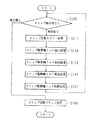
図9は、本発明の一実施形態による4輪駆動装置の直流電動機トルク算出手段の中のRスリップ直流電動機トルク補正手段の動作を示すフローチャートである。図10は、本発明の一実施形態による4輪駆動装置の直流電動機トルク算出手段の中のRスリップ直流電動機トルク補正手段が用いるトルク制限テーブルの説明図である。図11は、本発明の一実施形態による4輪駆動装置の直流電動機トルク算出手段の中のRスリップ直流電動機トルク補正手段の動作を示すタイミングチャートである。
Next, the operation of the R slip DC motor torque correcting means 139 in the DC motor torque calculating means of the four-wheel drive device according to the present embodiment will be described with reference to FIGS. 4 and 9 to 11.
FIG. 9 is a flowchart showing the operation of the R slip DC motor torque correcting means in the DC motor torque calculating means of the four-wheel drive device according to the embodiment of the present invention. FIG. 10 is an explanatory diagram of a torque limit table used by the R slip DC motor torque correcting means in the DC motor torque calculating means of the four-wheel drive device according to the embodiment of the present invention. FIG. 11 is a timing chart showing the operation of the R slip DC motor torque correcting means in the DC motor torque calculating means of the four-wheel drive device according to the embodiment of the present invention.
図4に示したように、Rスリップ直流電動機トルク補正手段139には、Rスリップ検出手段137の出力と、トルク切替手段133の出力が入力する。Rスリップ直流電動機トルク補正手段139は、Rスリップ検出手段137によって、後輪のスリップ状態が検出されると、図9に示すように、トルク切替手段133が出力する目標直流電動機トルクを補正して、後輪のスリップを収束するように、目標直流電動機トルクを補正する。図9の駆動制御ルーチンは、所定時間毎(例えば、10msec毎)に繰り返し実行される。
As shown in FIG. 4, the output of the R
図9のステップS100において、Rスリップ直流電動機トルク補正手段139は、Rスリップ検出手段137が出力するリアスリップフラグ(RSLP)に基づいて、後輪のスリップが発生しているか否かを判定する。後輪スリップが検出されるとステップS110に進み、検出されない場合にはステップS160に進む。 In step S100 of FIG. 9, the R slip DC motor torque correction means 139 determines whether or not a rear wheel slip has occurred based on the rear slip flag (RSLP) output from the R slip detection means 137. If a rear wheel slip is detected, the process proceeds to step S110, and if not detected, the process proceeds to step S160.
以下、後輪スリップが検出された場合について説明する。ここで、図11(A)は、スリップの発生状態を示している。図11(A)において、破線VWFが前輪車輪速を示し、実線VWRが後輪車輪速を示し、一点鎖線VBが車体速を示しており、前輪車輪速VWFは常に車体速VBより高く、すなわち前輪が常時スリップした状態を示している。ここでは、図8の加速度スリップ検出器137Dによって後輪スリップが検出されたものとする。例えば、図11(A)の後輪車輪速VWRの後輪スリップS1,S2,S3に示すように、後輪車輪速VWRが急激に増加した場合に、後輪スリップが発生したと検出される。このような場合、Rスリップ直流電動機トルク補正手段139は、図9のステップS110以降の処理を実行する。 Hereinafter, a case where a rear wheel slip is detected will be described. Here, FIG. 11A shows a state of occurrence of slip. In FIG. 11A, the broken line VWF indicates the front wheel speed, the solid line VWR indicates the rear wheel speed, the alternate long and short dash line VB indicates the vehicle speed, and the front wheel speed VWF is always higher than the vehicle speed VB. It shows a state where the front wheel is always slipping. Here, it is assumed that the rear wheel slip is detected by the acceleration slip detector 137D of FIG. For example, as shown in rear wheel slips S1, S2, and S3 of the rear wheel speed VWR in FIG. 11A, it is detected that the rear wheel slip has occurred when the rear wheel speed VWR increases rapidly. . In such a case, the R slip DC motor torque correction means 139 executes the processing after step S110 in FIG.
ステップS110において、Rスリップ直流電動機トルク補正手段139は、スリップ回転数カウント処理を実行し、スリップ回転数カウンタの内容に、+1を加算して、空転によるスリップが何回目であるかカウントアップする。スリップ回転数カウンタの内容が、それまでに発生したスリップの回数を示している。
In step S110, the R slip DC motor
次に、ステップS120において、Rスリップ直流電動機トルク補正手段139は、スリップ駆動輪トルク減少処理を実行する。後輪が空転してスリップした場合、後輪の駆動力を減少させる。すなわち、4WDコントロールユニット(4WDCU)100から高出力発電機2への出力指令を減少させ、直流電動機5の出力を減少させることで駆動力を減少させる。図11(B)において、実線は、目標駆動トルク値MTtを示し、破線は実際の駆動トルクTmを示している。例えば、図11(A)の時刻t1において、後輪スリップが検出されたとすると、図11(B)に示すように、時刻t1から後輪の目標駆動トルク値MTtを減少して、目標トルクがT0となるようなスリップ駆動輪トルク減少処理を実行する。
減少させる駆動トルクは、予め算出しておいた空転によるスリップが確実に収まる駆動トルクである。例えば、予め発進又は登坂可能とする路面さえ確定していれば、車両重量W、動摩擦係数Dμ、駆動力伝達効率をη、減速比G、タイヤ動半径をTRとすると、直流電動機5の駆動トルクT0は、
T0=W×Dμ×TR/G/ η
と計算できる。そこで、直流電動機5の駆動トルクTを、上述の駆動トルクT0よりも小さい値とすれば、空転によるスリップが確実に収まることになる。ここで、目標トルクT0は、例えば、0.3Nmである。なお、時刻t1からt2までの駆動トルクの減少度合い(直線の傾き)は、電動機5のトルク応答時定数に近い一定の傾き値としている。
Next, in step S120, the R slip DC motor torque correction means 139 executes slip drive wheel torque reduction processing. When the rear wheel slips and slips, the driving force of the rear wheel is reduced. That is, the output command from the 4WD control unit (4WDCU) 100 to the high-
The driving torque to be reduced is a driving torque that reliably calculates slip caused by idling calculated in advance. For example, if the road surface that can be started or climbed is determined in advance, if the vehicle weight W, the dynamic friction coefficient Dμ, the driving force transmission efficiency is η, the reduction ratio G, and the tire dynamic radius is TR, the driving torque of the
T0 = W × Dμ × TR / G / η
Can be calculated. Therefore, if the driving torque T of the
次に、ステップS130において、Rスリップ直流電動機トルク補正手段139は、スリップ駆動輪トルク保持処理を実行する。すなわち、図11(B)に示すように、時刻t11から時刻t12の間、減少した後輪の目標駆動トルク値T0を保持する。保持時間Δt(=t12−t11)は、例えば、0.1secである。目標駆動トルクを減少させ、さらに、一定時間保持することにより、より確実に空転によるスリップを収束させることができる。すなわち、減少させた駆動トルクは、車輪等の慣性モーメントにより空転によるスリップが収まらないことも考えられるため、一定時間減少させた駆動トルクを継続(保持)させることにより、より確実に空転によるスリップを収束させることができる。 Next, in step S130, the R slip DC motor torque correction means 139 executes slip drive wheel torque holding processing. That is, as shown in FIG. 11B, the target drive torque value T0 of the rear wheel that has decreased is maintained from time t11 to time t12 . The holding time Δt (= t12−t11 ) is, for example, 0.1 sec. By reducing the target drive torque and holding it for a certain period of time, slip due to idling can be more reliably converged. In other words, the reduced drive torque may not be able to stop slipping due to idling due to the inertia moment of the wheels, etc. Therefore, by continuing (holding) the driving torque that has been reduced for a certain period of time, slipping due to idling can be more reliably performed. It can be converged.
次に、ステップS140において、Rスリップ直流電動機トルク補正手段139は、スリップ駆動輪トルク増加処理を実行する。すなわち、図11(B)に示すように、目標駆動トルクMTtをトルクT1まで増加する。ここで、減少された駆動トルクを増加させる際、制限をせず駆動トルクを増加すると再度スリップが発生するため、ステップS140にて空転によるスリップ検出時のトルク以下まで駆動トルクを増加させる。目標駆動トルクを増加させることにより、走破性を向上することができ、また、その増加トルクをスリップ時のトルク以下とすることにより、再度のスリップを回避可能となる。 Next, in step S140, the R slip DC motor torque correction means 139 executes slip drive wheel torque increase processing. That is, as shown in FIG. 11B, the target drive torque MTt is increased to the torque T1. Here, when the decreased driving torque is increased, if the driving torque is increased without limitation, slip occurs again. Therefore , in step S140 , the driving torque is increased to less than or equal to the torque at the time of slip detection due to idling. By increasing the target drive torque, the running performance can be improved, and by making the increased torque equal to or less than the torque at the time of slip, it is possible to avoid another slip.
そして、ステップS140において、Rスリップ直流電動機トルク補正手段139は、スリップ駆動輪トルク制限処理を実行する。スリップ駆動輪トルク制限処理は、ステップS110でカウントしたスリップ回数Nに応じて、図10に示した駆動トルク制限テーブルに基づいて、制限駆動トルクLTを算出し、駆動トルクを制限駆動トルクLT以下となるよう高出力発電機2の出力指令を4WDコントロールユニット(4WDCU)100より制御することにより、数回の空転によるスリップにて駆動トルクが最適な値となり安定した走行が可能となる。すなわち、ステップS110でカウントされたスリップ回数に基づいて、スリップ回数Nが1回の場合には、制限駆動トルクLTが320Nmであり、スリップ回数Nが2回の場合には、制限駆動トルクLTが240Nmであるというように、スリップ回数Nが増加するほど、制限駆動トルクを小さくする。図11(A)に示すように、第1回目のスリップS1が発生した場合には、制限駆動トルクLTを320Nm(図11(A)のトルクT1)とする。
In step S140, the R slip DC motor
次に、ステップS100に戻り、スリップ検出を継続する。例えば、図11(A)に示すように、第2回目のスリップが発生すると、ステップS150の処理により、図10の制限テーブルを用いて、制限駆動トルクLTを240Nm(図11(A)のトルクT2)とする。さらに、第3回目のスリップが発生すると、ステップS150の処理により、図10の制限テーブルを用いて、制限駆動トルクLTを200Nm(図11(A)のトルクT3)とする。このように、繰り返しスリップが発生するときは、目標駆動トルクMTtを次第に減少するように制限することで、より確実にスリップを収束させることができる。
次に、ステップS100の判定でスリップが検出されないと、ステップS160において、Rスリップ直流電動機トルク補正手段139は、スリップ回数リセット処理を実行して、スリップ回数Nを0クリアする。
なお、スリップ回数Nの0クリアは、駆動トルクを増加した後、カウントしたスリップ回数をアクセル開度センサが0%となった場合、もしくは、空転によるスリップが一定時間ない場合、もしくは、路面μが回復した場合に0とするようにすることができる。スリップ回数を0クリアした後、制限をしていた駆動トルクを増加する。
Next, returning to step S100, slip detection is continued. For example, as shown in FIG. 11 (A), when the second slip occurs, the limit drive torque LT is set to 240 Nm (torque of FIG. 11 (A)) using the limit table of FIG. T2). Further, when the third slip occurs, the limit drive torque LT is set to 200 Nm (torque T3 in FIG. 11A) using the limit table in FIG. 10 by the process in step S150. As described above, when the slip repeatedly occurs, the slip can be more reliably converged by limiting the target drive torque MTt so as to gradually decrease.
Next, if no slip is detected in the determination in step S100, in step S160, the R slip DC motor
Note that the slip count N is cleared to 0 when the driving torque is increased and the counted slip count is 0% in the accelerator opening sensor, or there is no slippage due to idling, or when the road surface μ is It can be set to 0 when recovered. After clearing the number of slips to zero, the driving torque that was limited is increased.
なお、上述のステップS120の処理では、空転によるスリップをしている後輪の駆動力を減少させるため、直流電動機5の出力トルクを減少させたが、クラッチ4を開放して、機械的に直流電動機5を車軸より切り離すようにしてもよいものである。この場合、駆動力は一時的に0Nmまで低下することとなる。
In the process of step S120 described above, the output torque of the
また、空転によるスリップをしている車輪の駆動力の減少方法については、一定の傾きにて減少することとしても良いが空転によるスリップを抑制するため、急激に減少させることが望ましいものである。 Further, as for the method of reducing the driving force of the wheel that is slipping due to idling, it may be reduced at a constant inclination, but it is desirable to reduce it rapidly in order to suppress slipping due to idling.
また、上述のステップS140の処理では、駆動トルクの増加時に、一定の傾きにて増加することとしても良いが、空転によるスリップを即抑制するには、急激に増加させることが望ましいものである。 In the process of step S140 described above, the driving torque may be increased with a constant slope. However, it is desirable to increase the driving torque rapidly in order to immediately suppress slipping due to idling.
以上説明したように、本実施形態の制御方法によれば、低μ路での走行において、図11(B)に示したような駆動力となり、スリップが抑制されると共に、有効なトラクションが確保でき、安定した走行ができるものである。
As described above, according to the control method of the present embodiment, in driving on a low μ road, the driving force shown in FIG. 11B is obtained, slip is suppressed, and effective traction is ensured. It is possible to run stably.
1…エンジン
2…高出力発電機
3…デファレンシャルギヤ
4…クラッチ
5…直流電動機
7…大容量リレー
8…エンジンコントロールユニット
9…トランスミッションコントロールユニット
10…アンチロックブレーキコントロールユニット
11…補機バッテリ
12…トランスミッション
13…補機発電機
14R,14L…前輪
15R,15L…後輪
16R,16L…前輪車輪速センサ
17R,17L…後輪車輪速センサ
100…4WDコントロールユニット
110…モード判定手段
130…直流電動機トルク算出手段
131…アクセル感応トルク演算手段
133…トルク切替手段
135…前後輪速差感応トルク演算手段
137…Rスリップ検出手段
137A,137B,137C…微分器
137D…加速度スリップ検出器
137E…幾何スリップ検出器
137F…左右差スリップ検出器
137G…OR回路
139…Rスリップ直流電動機トルク補正手段
150…ドライバ手段
152…直流電動機界磁電流算出手段
154…オルタ界磁電流算出手段
156,158…減算器
DESCRIPTION OF
Claims (4)
前記4つの車輪のうち、内燃機関によって駆動される前輪とは異なる後輪を駆動する電動機と、
前記内燃機関によって駆動され、前記電動機の電機子コイルに駆動用電力を供給する発電機と、
前記前輪のスリップ及び前記後輪のスリップを検出するためのスリップ検出手段と、
該スリップ検出手段により前記前輪のスリップが検出されて、前輪速と後輪速との差に基づいて算出した前記前輪のスリップ状態を収束させるための駆動トルクを前記電動機から前記後輪に供給しているときに、前記スリップ検出手段により前記後輪のスリップが検出された場合には、前記電動機から前記後輪に供給される駆動トルクを、前記後輪のスリップが収束する予め算出した駆動トルクまで減少させてから増加させるように、前記駆動トルクを補正すると共に、それでも前記スリップ検出手段により前記後輪のスリップが繰り返し検出される場合には、前記後輪のスリップが繰り返し検出される路面状態にある間、前記電動機から前記後輪に供給される駆動トルクを、前記後輪のスリップが収束する予め算出した駆動トルクまで減少させてから増加させる、という動作が繰り返されるように、前記駆動トルクを補正するトルク補正手段と、を有し、
前記トルク補正手段は、前記スリップの回数に対応する駆動トルク制限値を備え、前記増加させる駆動トルクを、前記スリップの回数に応じて、前記スリップの回数が増加するほど駆動トルク制限値が小さくなるように、前記スリップの回数に対応する駆動トルク制限値まで増加させる、
ことを特徴とする車両駆動装置。 A drive device mounted on a vehicle that drives by driving four wheels,
Of the four wheels, an electric motor that drives a rear wheel different from a front wheel driven by an internal combustion engine;
A generator driven by the internal combustion engine to supply driving power to an armature coil of the motor;
Slip detecting means for detecting the slip of the front wheel and the slip of the rear wheel;
The slip detection means detects the slip of the front wheel, and supplies a driving torque from the motor to the rear wheel for converging the slip state of the front wheel calculated based on the difference between the front wheel speed and the rear wheel speed. When the slip detection means detects the slip of the rear wheel, the drive torque supplied from the electric motor to the rear wheel is calculated as the drive torque calculated in advance so that the rear wheel slip converges. The road surface state in which the driving torque is corrected so as to decrease and then increase, and still when the slip detection means repeatedly detects the slip of the rear wheel, the slip of the rear wheel is repeatedly detected. The driving torque supplied from the electric motor to the rear wheel is reduced to a pre-calculated driving torque at which the rear wheel slip converges. As operation is repeated as to increase the allowed has a torque correcting means for correcting the driving torque,
The torque correction means includes a drive torque limit value corresponding to the number of slips, and the drive torque limit value decreases as the number of slips increases according to the number of slips. And increasing the driving torque limit value corresponding to the number of slips,
The vehicle drive device characterized by the above-mentioned.
前記トルク補正手段は、前記減少させた駆動トルクを所定時間、保持した後、前記駆動トルクを増加させる、
ことを特徴とする車両駆動装置。 In the vehicle drive device according to claim 1,
The torque correction means increases the drive torque after holding the reduced drive torque for a predetermined time;
The vehicle drive device characterized by the above-mentioned.
前記4つの車輪のうち、内燃機関によって駆動される前輪とは異なる後輪を駆動する電動機と、
前記内燃機関によって駆動され、前記電動機の電機子コイルに駆動用電力を供給する発電機と、
前記発電機の発電を制御して前記駆動用電力を制御し、前記電動機の駆動を制御する制御装置と、を有し、
前記前輪にスリップが発生したとき、前輪速と後輪速との差に基づいて算出した前記前輪のスリップ状態を収束させるための駆動トルクが前記電動機から前記後輪に供給しているときに、前記後輪にスリップが発生した場合には、前記電動機から前記後輪に供給される駆動トルクを、前記後輪のスリップが収束する予め算出した駆動トルクまで減少させてから増加させるように、前記駆動トルクを補正すると共に、それでも前記スリップ検出手段により前記後輪のスリップが繰り返し検出される場合には、前記スリップが繰り返し発生する路面状態にある間、前記電動機から前記後輪に伝達される駆動トルクが、前記スリップを収束する予め算出した駆動トルクに減少してから増加する、という動作が繰り返されるように、前記制御装置から前記発電機に出力される発電指令を増減させ、
前記制御装置は、前記スリップの回数に対応する駆動トルク制限値を備え、前記増加させる駆動トルクを、前記スリップの回数に応じて、前記スリップの回数が増加するほど駆動トルク制限値が小さくなるように、前記スリップの回数に対応する駆動トルク制限値まで増加させる、
ことを特徴とする車両駆動装置。 A drive device mounted on a vehicle that drives by driving four wheels,
Of the four wheels, an electric motor that drives a rear wheel different from a front wheel driven by an internal combustion engine;
A generator driven by the internal combustion engine to supply driving power to an armature coil of the motor;
A control device that controls power generation by controlling power generation of the generator and controlling driving of the electric motor,
When slip occurs in the front wheel, when driving torque for converging the slip state of the front wheel calculated based on the difference between the front wheel speed and the rear wheel speed is supplied from the electric motor to the rear wheel, When slip occurs in the rear wheel, the driving torque supplied from the electric motor to the rear wheel is reduced to a pre-calculated driving torque at which the rear wheel slip converges, and then increased. When the driving torque is corrected and the slip detection means repeatedly detects the slip of the rear wheel, the drive transmitted from the motor to the rear wheel while the slip is repeatedly generated on the road surface. From the control device, the operation is repeated such that the torque is reduced to a pre-calculated driving torque that converges the slip and then increased. The power generation command that is output to the serial generator is increased or decreased,
The control device includes a drive torque limit value corresponding to the number of slips, and the drive torque limit value decreases as the number of slips increases according to the number of slips. And increasing the driving torque limit value corresponding to the number of slips,
The vehicle drive device characterized by the above-mentioned.
前記減少させた駆動トルクが所定時間、保持された後、前記駆動トルクが増加するように、前記減少させた発電指令を所定時間、保持した後、増加させる
ことを特徴とする車両駆動装置。 The vehicle drive device according to claim 3,
A vehicle drive device characterized in that the reduced power generation command is increased after being held for a predetermined time so that the drive torque is increased after the reduced drive torque is held for a predetermined time.
Priority Applications (4)
| Application Number | Priority Date | Filing Date | Title |
|---|---|---|---|
| JP2003430149A JP4625632B2 (en) | 2003-12-25 | 2003-12-25 | Vehicle drive device |
| US11/017,724 US7392875B2 (en) | 2003-12-25 | 2004-12-22 | Four-wheel drive system |
| EP04030742A EP1547841B1 (en) | 2003-12-25 | 2004-12-23 | Four-wheel drive system |
| CNB2004101045523A CN1330512C (en) | 2003-12-25 | 2004-12-23 | Four-wheel drive system |
Applications Claiming Priority (1)
| Application Number | Priority Date | Filing Date | Title |
|---|---|---|---|
| JP2003430149A JP4625632B2 (en) | 2003-12-25 | 2003-12-25 | Vehicle drive device |
Publications (2)
| Publication Number | Publication Date |
|---|---|
| JP2005186756A JP2005186756A (en) | 2005-07-14 |
| JP4625632B2 true JP4625632B2 (en) | 2011-02-02 |
Family
ID=34545020
Family Applications (1)
| Application Number | Title | Priority Date | Filing Date |
|---|---|---|---|
| JP2003430149A Expired - Fee Related JP4625632B2 (en) | 2003-12-25 | 2003-12-25 | Vehicle drive device |
Country Status (4)
| Country | Link |
|---|---|
| US (1) | US7392875B2 (en) |
| EP (1) | EP1547841B1 (en) |
| JP (1) | JP4625632B2 (en) |
| CN (1) | CN1330512C (en) |
Families Citing this family (43)
| Publication number | Priority date | Publication date | Assignee | Title |
|---|---|---|---|---|
| JP4135682B2 (en) * | 2004-06-07 | 2008-08-20 | 日産自動車株式会社 | Vehicle driving force control device |
| FR2886411B1 (en) * | 2005-05-31 | 2008-01-11 | Valeo Equip Electr Moteur | METHOD AND DEVICE FOR ESTIMATING THE CURRENT DELIVERED BY AN ALTERNATOR FOR A MOTOR VEHICLE |
| JP4636994B2 (en) * | 2005-10-24 | 2011-02-23 | 日立オートモティブシステムズ株式会社 | Vehicle drive device |
| JP2007245899A (en) * | 2006-03-15 | 2007-09-27 | Nissan Motor Co Ltd | Driving force controller for electric motor type four wheel drive vehicle |
| JP4820243B2 (en) | 2006-08-31 | 2011-11-24 | 日立オートモティブシステムズ株式会社 | Automotive control device |
| JP4905085B2 (en) * | 2006-11-29 | 2012-03-28 | 日産自動車株式会社 | Driving force distribution control device for four-wheel drive vehicles |
| JP4516576B2 (en) | 2007-01-31 | 2010-08-04 | 日立オートモティブシステムズ株式会社 | Vehicle drive device |
| JP2008222019A (en) | 2007-03-13 | 2008-09-25 | Hitachi Ltd | Vehicle drive system |
| US7832518B2 (en) * | 2007-03-22 | 2010-11-16 | Ford Global Technologies, Llc | Torque distribution control in a motor vehicle |
| KR20120048715A (en) * | 2007-06-27 | 2012-05-15 | 미쓰비시덴키 가부시키가이샤 | Controller for electric vehicle |
| JP2009006873A (en) * | 2007-06-28 | 2009-01-15 | Honda Motor Co Ltd | Vehicular drive control apparatus |
| US8604709B2 (en) * | 2007-07-31 | 2013-12-10 | Lsi Industries, Inc. | Methods and systems for controlling electrical power to DC loads |
| US8903577B2 (en) * | 2009-10-30 | 2014-12-02 | Lsi Industries, Inc. | Traction system for electrically powered vehicles |
| WO2009128815A1 (en) * | 2008-04-14 | 2009-10-22 | Deere & Company | Traction control method and apparatus for a vehicle with independent drives |
| US8006550B2 (en) * | 2009-04-13 | 2011-08-30 | GM Global Technology Operations LLC | Methods and systems for testing tires of vehicles to quantify transient tire force and moment responses |
| JP4846003B2 (en) * | 2009-08-05 | 2011-12-28 | 本田技研工業株式会社 | Torque distribution control device for four-wheel drive vehicle |
| JP5211002B2 (en) | 2009-09-15 | 2013-06-12 | 日立オートモティブシステムズ株式会社 | Drive control device |
| US8708074B1 (en) * | 2010-06-15 | 2014-04-29 | Hydro-Gear Limited Partnership | Selectable four-wheel drive system |
| JP5652020B2 (en) * | 2010-06-30 | 2015-01-14 | 日産自動車株式会社 | Creep cut control device for electric vehicle |
| JP5521834B2 (en) * | 2010-06-30 | 2014-06-18 | 日産自動車株式会社 | Creep cut control device for electric vehicle |
| JP5720165B2 (en) * | 2010-10-05 | 2015-05-20 | 株式会社ジェイテクト | Four-wheel drive vehicle |
| DE102010053414A1 (en) * | 2010-12-06 | 2012-06-06 | GM Global Technology Operations LLC | Drive unit, in particular rear-drive unit, for a four-wheel drive of a motor vehicle |
| GB2488155A (en) * | 2011-02-18 | 2012-08-22 | Land Rover Uk Ltd | Driveline transition based on wheel slip |
| US8965609B2 (en) * | 2011-12-29 | 2015-02-24 | Kawasaki Jukogyo Kabushiki Kaisha | Electric vehicle |
| JP5764103B2 (en) * | 2012-09-07 | 2015-08-12 | 株式会社アドヴィックス | Brake control device for vehicle |
| KR101396070B1 (en) | 2012-10-19 | 2014-05-15 | 현대중공업 주식회사 | Slip control method of propulsion control system for high speed train |
| JP5979247B2 (en) * | 2012-12-11 | 2016-08-24 | 日産自動車株式会社 | Driving force distribution control device for four-wheel drive vehicle |
| JP6223717B2 (en) * | 2013-06-03 | 2017-11-01 | Ntn株式会社 | Electric vehicle slip control device |
| JP6342188B2 (en) * | 2013-07-08 | 2018-06-13 | Ntn株式会社 | Electric vehicle slip control device |
| US9139088B2 (en) * | 2013-08-30 | 2015-09-22 | Ford Global Technologies, Llc | System and method for hybrid vehicle control during wheel slip events to limit generator speed |
| CN103600744B (en) * | 2013-10-25 | 2016-03-30 | 山东省计算中心 | The path maintenance of four-wheel steering/driving vehicle and the control method of wheel side sliding |
| CN105829184B (en) * | 2013-12-17 | 2019-01-04 | 本田技研工业株式会社 | Vehicle |
| CN104029677B (en) * | 2014-05-26 | 2016-04-13 | 北京理工大学 | A kind of control method of distributed-driving electric automobile |
| CA2976967C (en) * | 2015-02-17 | 2018-04-17 | Honda Motor Co.,Ltd. | Hydraulic control device for drive power distribution device |
| US20180257477A1 (en) * | 2015-09-12 | 2018-09-13 | GM Global Technology Operations LLC | Traction management control system for vehicle having independently driven axles |
| WO2019074581A1 (en) * | 2017-10-11 | 2019-04-18 | Cummins Inc. | Torque deration in response traction control events |
| KR102478125B1 (en) * | 2017-11-24 | 2022-12-16 | 현대자동차주식회사 | Control method and system for motor drive vehicle |
| KR20210014821A (en) * | 2019-07-30 | 2021-02-10 | 현대자동차주식회사 | Wheel slip control method for vehicle |
| US11376955B2 (en) * | 2019-08-29 | 2022-07-05 | Kawasaki Motors, Ltd. | Utility vehicle |
| JP7200910B2 (en) | 2019-11-05 | 2023-01-10 | トヨタ自動車株式会社 | Vehicle driving force control device |
| CN112078381A (en) * | 2020-09-18 | 2020-12-15 | 北京车和家信息技术有限公司 | Torque distribution control method and device, driving system and vehicle |
| US11338796B1 (en) * | 2020-12-17 | 2022-05-24 | GM Global Technology Operations LLC | Apparatus and methodology for wheel stability monitoring system |
| US11872994B2 (en) * | 2021-10-30 | 2024-01-16 | Zoox, Inc. | Estimating vehicle velocity |
Family Cites Families (26)
| Publication number | Priority date | Publication date | Assignee | Title |
|---|---|---|---|---|
| JPH07106007B2 (en) | 1985-01-21 | 1995-11-13 | 株式会社日立製作所 | Adhesion control device for railway vehicles |
| JPH088728B2 (en) | 1985-08-14 | 1996-01-29 | 株式会社日立製作所 | Electric vehicle readhesion control device |
| JPS6260936A (en) | 1985-09-09 | 1987-03-17 | Toyota Motor Corp | Output control device for internal combustion engine |
| JPS62121839A (en) | 1985-11-22 | 1987-06-03 | Toyota Motor Corp | Slip control device for vehicle |
| US5016724A (en) * | 1989-08-08 | 1991-05-21 | Twin Disc, Incorporated | Inter-axle differential having a friction-type biasing clutch and wheel slip sensing control means therefor |
| JPH03249350A (en) * | 1990-02-27 | 1991-11-07 | Mitsubishi Motors Corp | Power controller for vehicle |
| JP3571370B2 (en) * | 1994-06-27 | 2004-09-29 | 富士重工業株式会社 | Vehicle driving force control device |
| JPH08182118A (en) | 1994-12-22 | 1996-07-12 | Fuji Heavy Ind Ltd | Drive controller for electric vehicle |
| JP3526675B2 (en) * | 1995-09-14 | 2004-05-17 | 日産ディーゼル工業株式会社 | Wheel drive torque control device |
| JP3358452B2 (en) * | 1996-07-22 | 2002-12-16 | 日産自動車株式会社 | Vehicle engine brake control device |
| JP2000168387A (en) * | 1998-12-08 | 2000-06-20 | Honda Motor Co Ltd | Electric motor drive force-assisting vehicle |
| JP3983917B2 (en) | 1999-02-23 | 2007-09-26 | 本田技研工業株式会社 | Electric drive device for vehicle |
| JP3449284B2 (en) * | 1999-03-16 | 2003-09-22 | 日産自動車株式会社 | Four-wheel drive |
| JP2000318474A (en) * | 1999-05-12 | 2000-11-21 | Honda Motor Co Ltd | Front and rear wheel driving vehicle |
| JP3852250B2 (en) * | 1999-08-27 | 2006-11-29 | トヨタ自動車株式会社 | Control device for front and rear wheel drive vehicle |
| JP2001105919A (en) * | 1999-10-08 | 2001-04-17 | Toyota Motor Corp | Control device for front and rear wheel driven vehicle |
| JP3585798B2 (en) * | 1999-12-24 | 2004-11-04 | 本田技研工業株式会社 | Driving force control device for four-wheel drive vehicle |
| US6528959B2 (en) * | 2000-07-19 | 2003-03-04 | Honda Giken Kogyo Kabushiki Kaisha | Driving force control system for front-and-rear wheel drive vehicles |
| US6575870B2 (en) * | 2000-07-21 | 2003-06-10 | Honda Giken Kogyo Kabushiki Kaisha | Driving force control system for front-and-rear wheel drive vehicles |
| JP4227723B2 (en) | 2000-08-25 | 2009-02-18 | トヨタ自動車株式会社 | Four-wheel drive electric vehicle and control method thereof |
| US6859715B2 (en) * | 2000-10-11 | 2005-02-22 | Visteon Global Technologies, Inc. | Torque-biasing system |
| JP2002127773A (en) * | 2000-10-20 | 2002-05-08 | Fuji Heavy Ind Ltd | Drive force distribution device of four-wheel drive vehicle |
| US6535809B1 (en) * | 2000-11-08 | 2003-03-18 | Delphi Technologies, Inc. | Vehicle engine torque control with engine drag control mode |
| JP3546408B2 (en) | 2000-11-13 | 2004-07-28 | 本田技研工業株式会社 | Control device for front and rear wheel drive vehicles |
| JP2002347477A (en) | 2001-05-25 | 2002-12-04 | Nissan Motor Co Ltd | Driving system controlling device for four-wheel drive vehicle |
| JP4092502B2 (en) | 2003-12-19 | 2008-05-28 | 日産自動車株式会社 | Motor output control device for motor four-wheel drive vehicle |
-
2003
- 2003-12-25 JP JP2003430149A patent/JP4625632B2/en not_active Expired - Fee Related
-
2004
- 2004-12-22 US US11/017,724 patent/US7392875B2/en not_active Expired - Fee Related
- 2004-12-23 CN CNB2004101045523A patent/CN1330512C/en not_active Expired - Fee Related
- 2004-12-23 EP EP04030742A patent/EP1547841B1/en not_active Not-in-force
Also Published As
| Publication number | Publication date |
|---|---|
| CN1330512C (en) | 2007-08-08 |
| EP1547841B1 (en) | 2011-09-28 |
| US20050150702A1 (en) | 2005-07-14 |
| US7392875B2 (en) | 2008-07-01 |
| JP2005186756A (en) | 2005-07-14 |
| EP1547841A2 (en) | 2005-06-29 |
| CN1636789A (en) | 2005-07-13 |
| EP1547841A3 (en) | 2006-10-11 |
Similar Documents
| Publication | Publication Date | Title |
|---|---|---|
| JP4625632B2 (en) | Vehicle drive device | |
| JP4371270B2 (en) | Vehicle driving force device | |
| US7451850B2 (en) | Drive control apparatus and method for vehicles | |
| KR100698993B1 (en) | Driving force control apparatus for automotive vehicles | |
| JP3539422B2 (en) | Driving force control device for four-wheel drive vehicle | |
| KR100618505B1 (en) | Vehicle driving force control apparatus | |
| JP4516577B2 (en) | Vehicle drive device | |
| EP1669237A2 (en) | Vehicle driving force control system | |
| KR100623126B1 (en) | Vehicle driving force control apparatus | |
| JP3333488B2 (en) | Electric four-wheel drive system for vehicles | |
| JP3555617B2 (en) | Vehicle driving force control device | |
| JP3891166B2 (en) | Vehicle driving force control device | |
| JP2009220711A (en) | Vehicular controller and vehicular control method | |
| JP3610972B2 (en) | Vehicle driving force control device | |
| JP2009214805A (en) | Driving force control device for vehicle | |
| JP2008001185A (en) | Driving force controller for vehicles | |
| JP3891165B2 (en) | Vehicle drive control device | |
| JP2003136992A (en) | Driving power distribution control device for four wheel drive vehicle | |
| JP4151622B2 (en) | Vehicle drive control device | |
| JP4001141B2 (en) | Vehicle driving force control device | |
| JP2007331685A (en) | Driving force control device for vehicle and driving device | |
| JP2004082892A (en) | Clutch engagement controller for vehicle | |
| JP2007333168A (en) | Driving force control device and driving device for vehicle | |
| JP2009107503A (en) | Vehicle drive unit and on-vehicle electronic control device used therefor |
Legal Events
| Date | Code | Title | Description |
|---|---|---|---|
| A621 | Written request for application examination |
Free format text: JAPANESE INTERMEDIATE CODE: A621 Effective date: 20060216 |
|
| A131 | Notification of reasons for refusal |
Free format text: JAPANESE INTERMEDIATE CODE: A131 Effective date: 20070206 |
|
| A521 | Request for written amendment filed |
Free format text: JAPANESE INTERMEDIATE CODE: A523 Effective date: 20070409 |
|
| A131 | Notification of reasons for refusal |
Free format text: JAPANESE INTERMEDIATE CODE: A131 Effective date: 20071211 |
|
| A521 | Request for written amendment filed |
Free format text: JAPANESE INTERMEDIATE CODE: A523 Effective date: 20080128 |
|
| A131 | Notification of reasons for refusal |
Free format text: JAPANESE INTERMEDIATE CODE: A131 Effective date: 20080812 |
|
| A521 | Request for written amendment filed |
Free format text: JAPANESE INTERMEDIATE CODE: A523 Effective date: 20081009 |
|
| A02 | Decision of refusal |
Free format text: JAPANESE INTERMEDIATE CODE: A02 Effective date: 20081104 |
|
| A521 | Request for written amendment filed |
Free format text: JAPANESE INTERMEDIATE CODE: A523 Effective date: 20090219 |
|
| A711 | Notification of change in applicant |
Free format text: JAPANESE INTERMEDIATE CODE: A712 Effective date: 20100106 |
|
| A521 | Request for written amendment filed |
Free format text: JAPANESE INTERMEDIATE CODE: A523 Effective date: 20100531 |
|
| A521 | Request for written amendment filed |
Free format text: JAPANESE INTERMEDIATE CODE: A523 Effective date: 20100915 |
|
| A01 | Written decision to grant a patent or to grant a registration (utility model) |
Free format text: JAPANESE INTERMEDIATE CODE: A01 |
|
| A61 | First payment of annual fees (during grant procedure) |
Free format text: JAPANESE INTERMEDIATE CODE: A61 Effective date: 20101108 |
|
| R150 | Certificate of patent or registration of utility model |
Free format text: JAPANESE INTERMEDIATE CODE: R150 |
|
| FPAY | Renewal fee payment (event date is renewal date of database) |
Free format text: PAYMENT UNTIL: 20131112 Year of fee payment: 3 |
|
| LAPS | Cancellation because of no payment of annual fees |