JP4625377B2 - Fast failure detection and recovery for Internet protocol phones - Google Patents
Fast failure detection and recovery for Internet protocol phones Download PDFInfo
- Publication number
- JP4625377B2 JP4625377B2 JP2005177179A JP2005177179A JP4625377B2 JP 4625377 B2 JP4625377 B2 JP 4625377B2 JP 2005177179 A JP2005177179 A JP 2005177179A JP 2005177179 A JP2005177179 A JP 2005177179A JP 4625377 B2 JP4625377 B2 JP 4625377B2
- Authority
- JP
- Japan
- Prior art keywords
- keep
- paths
- packets
- alive
- destination node
- Prior art date
- Legal status (The legal status is an assumption and is not a legal conclusion. Google has not performed a legal analysis and makes no representation as to the accuracy of the status listed.)
- Expired - Fee Related
Links
Images


Classifications
-
- H—ELECTRICITY
- H04—ELECTRIC COMMUNICATION TECHNIQUE
- H04L—TRANSMISSION OF DIGITAL INFORMATION, e.g. TELEGRAPHIC COMMUNICATION
- H04L43/00—Arrangements for monitoring or testing data switching networks
- H04L43/50—Testing arrangements
-
- H—ELECTRICITY
- H04—ELECTRIC COMMUNICATION TECHNIQUE
- H04L—TRANSMISSION OF DIGITAL INFORMATION, e.g. TELEGRAPHIC COMMUNICATION
- H04L65/00—Network arrangements, protocols or services for supporting real-time applications in data packet communication
- H04L65/80—Responding to QoS
-
- H—ELECTRICITY
- H04—ELECTRIC COMMUNICATION TECHNIQUE
- H04L—TRANSMISSION OF DIGITAL INFORMATION, e.g. TELEGRAPHIC COMMUNICATION
- H04L69/00—Network arrangements, protocols or services independent of the application payload and not provided for in the other groups of this subclass
- H04L69/40—Network arrangements, protocols or services independent of the application payload and not provided for in the other groups of this subclass for recovering from a failure of a protocol instance or entity, e.g. service redundancy protocols, protocol state redundancy or protocol service redirection
-
- H—ELECTRICITY
- H04—ELECTRIC COMMUNICATION TECHNIQUE
- H04L—TRANSMISSION OF DIGITAL INFORMATION, e.g. TELEGRAPHIC COMMUNICATION
- H04L43/00—Arrangements for monitoring or testing data switching networks
- H04L43/10—Active monitoring, e.g. heartbeat, ping or trace-route
Description
本発明は一般に、IP(インターネット・プロトコル)電話ベース・ネットワークなどの通信ネットワークに関し、より詳細には、そのようなネットワークにおける障害の検出および復旧を高速に実施するための技術に関する。 The present invention relates generally to communication networks such as IP (Internet Protocol) telephone-based networks, and more particularly to techniques for performing fast fault detection and recovery in such networks.
本出願は、2004年6月18日出願の米国特許仮出願第60/581329号の優先権を主張するものであり、その開示を参照により本明細書に組み込む。 This application claims priority from US Provisional Application No. 60 / 581,329, filed Jun. 18, 2004, the disclosure of which is incorporated herein by reference.
コストを抑え、新しいサービスを可能にするためにIP電話への関心が高まっている。多くの企業やコール・センタが集中IPインフラ上のIP電話を採用し、多くのマルチサイト企業がイントラ通信またはサイト間通信にVoIP(ボイス・オーバIP)を使用している。 There is growing interest in IP telephony to keep costs down and enable new services. Many companies and call centers employ IP telephones on a centralized IP infrastructure, and many multi-site companies use VoIP (voice over IP) for intra-communication or inter-site communication.
ミッションクリティカルなビジネス・アプリケーションにVoIPを使用するには、VoIP通話の信頼性および品質を評価し、高めることが重要である。理想的には、VoIP通話には、従来の回線交換方式の電話通話と同等の信頼性が必要である。しかし、VoIP通話(特に、広域リンク上のもの)の品質を監視し評価すると、従来の回線交換方式のネットワークでは生じない、IPネットワークに関する固有のパケット損失、遅延、およびジッタを処理することが必要になる。ほとんどのIPネットワークは、ネットワーク障害に対しては自己復旧であり、多くの企業ネットワークは、サイト間に冗長リンクまたは経路を備えるように設計されている。しかし、今日のIPネットワークは、音声に必要とされる時間尺度での性能低下に対処するようには設計されていない。例えば、最近の研究によると、サービス・プロバイダー・ネットワークの中には許容できる性能のものも存在するが、多くのバックボーン経路では、相変わらずVoIP性能が不十分であり、ネットワーク障害により問題が発生することが示されている。 To use VoIP for mission-critical business applications, it is important to evaluate and enhance the reliability and quality of VoIP calls. Ideally, a VoIP call needs to have the same reliability as a conventional circuit-switched telephone call. However, when monitoring and evaluating the quality of VoIP calls (especially on wide area links), it is necessary to handle the inherent packet loss, delay, and jitter associated with IP networks that do not occur in traditional circuit-switched networks become. Most IP networks are self-healing against network failures, and many enterprise networks are designed with redundant links or paths between sites. However, today's IP networks are not designed to deal with the performance degradation on the time scale required for voice. For example, according to recent research, some service provider networks have acceptable performance, but many backbone routes still have insufficient VoIP performance, causing problems due to network failures. It is shown.
ロバストなVoIPインフラストラクチャを提供するためには、性能低下や障害を高速に検出することが重要である。この検出は、いくつかの要因により複雑なものになっている。例えば、接続ベースでは、VoIP通話には、(例えば、通話の当事者が話さずに聞いているときなど、)パケットがソースから送信されない固有の無音期間が存在する。したがって、(例えば、受信側で)VoIP通話を監視するときには、自然な会話の沈黙、あるいは会話の圧縮などによって生ずるギャップと、IPネットワークのパケット損失、遅延、およびジッタによって生ずるギャップとを区別する必要がある。また、問題を検出することによって、確かにネットワーク管理者に警告をだすことができるようにはなるが、ネットワークが、検出された問題に対処し、それを回避できればさらに有用であろう。
したがって、IP電話ネットワーク、詳細にはVoIPアプリケーションを提供するIP電話ネットワークなどの通信ネットワークにおいて、障害の検出および復旧を高速に実施するための技術が必要とされている。 Therefore, there is a need for a technique for performing failure detection and recovery at high speed in a communication network such as an IP telephone network, specifically, an IP telephone network that provides a VoIP application.
本発明は、通信ネットワークにおいて、障害の検出および復旧を高速に実施するための技術を提供する。これに限定されるものではないが、本発明は、IP電話ネットワーク、詳細にはVoIPアプリケーションを提供するIP電話ネットワークに、特に適したものである。 The present invention provides a technique for performing failure detection and recovery at high speed in a communication network. Without being limited thereto, the present invention is particularly suitable for IP telephony networks, particularly IP telephony networks that provide VoIP applications.
例えば、本発明の一態様では、通信ネットワークの1つまたは複数の状態を検出する技術は、以下の工程/動作を含む。1つまたは複数のキープアライブ・パケットが、通信ネットワークのソース・ノードから通信ネットワークの宛先ノードに、ソース・ノードと宛先ノードの間の複数の経路を介して送信される。この場合、この複数の経路は、少なくとも一部が分離している。宛先ノードで、1つまたは複数のキープアライブ・パケットを2つ以上の経路を介して受信したとき、宛先ノードで、その2つ以上の各経路に対して少なくとも1つの品質尺度が計算される。この少なくとも1つの品質尺度は、通信ネットワークにおける1つまたは複数の状態を示すものである。 For example, in one aspect of the invention, a technique for detecting one or more states of a communication network includes the following steps / operations. One or more keep-alive packets are transmitted from a source node of the communication network to a destination node of the communication network via a plurality of paths between the source node and the destination node. In this case, at least a part of the plurality of paths is separated. When the destination node receives one or more keep-alive packets via two or more paths, at the destination node, at least one quality measure is calculated for each of the two or more paths. The at least one quality measure is indicative of one or more conditions in the communication network.
さらに、この品質尺度は、2つ以上の経路の各々について比較することができる。比較の結果は、宛先ノードからソース・ノードに送信することができる。受信した結果の少なくとも一部に基づいて、ソース・ノードから1つまたは複数の通信パケットを送信することができる。 Furthermore, this quality measure can be compared for each of two or more paths. The result of the comparison can be sent from the destination node to the source node. One or more communication packets can be transmitted from the source node based at least in part on the received results.
したがって、一例として例示的実施形態に従えば、短い、低帯域幅のキープアライブ・パケットをVoIPパケット・ストリームに投入して、障害やネットワーク状態の低下(例えば、遅延、ジッタ、または損失の増加)を高速に検出することができる。キープアライブ・パケットは、複製することができ、それらを使用して主ネットワーク経路および代替ネットワーク経路の遅延および損失特性を継続的に監視し比較することができる。その結果、障害またはQoS状態の低下が検出されたときは、(進行中の、およびその後の)通話を代替ルーティング経路(または回線交換PSTN)に高速に切り換える制御を支援することができる。キープアライブ・パケットの複製を複数の経路を介して同時に送信して遅延差を測定し比較することによって、この技術は、多くの共通の同期およびタイミングの誤差を回避する。 Thus, according to an exemplary embodiment, by way of example, a short, low bandwidth keepalive packet is injected into the VoIP packet stream to cause failure or network condition degradation (eg, increased delay, jitter, or loss). Can be detected at high speed. Keep-alive packets can be duplicated and used to continuously monitor and compare the delay and loss characteristics of the primary and alternate network paths. As a result, when a failure or a drop in QoS state is detected, it is possible to assist in the control of rapidly switching a call (in progress and subsequent) to an alternative routing path (or circuit switched PSTN). This technique avoids many common synchronization and timing errors by sending duplicate copies of keep-alive packets simultaneously over multiple paths to measure and compare differential delays.
本発明の、これらおよび他の目的、特徴、利点は、本発明の例示的実施形態についての以下の詳細な説明を、添付の図面と併せて読むことによって明らかになるはずである。 These and other objects, features, and advantages of the present invention will become apparent upon reading the following detailed description of exemplary embodiments of the invention in conjunction with the accompanying drawings.
本発明は、VoIP機能を備えたIP電話ベース・ネットワークの文脈のもとに説明するが、本発明がそれに限定されるものではないことを理解されたい。すなわち、本発明は、より一般的に、通信ネットワークの1つまたは複数の状態を検出することが望まれる、任意の通信ネットワークに適用可能である。 Although the present invention will be described in the context of an IP telephone-based network with VoIP capabilities, it should be understood that the present invention is not so limited. That is, the present invention is more generally applicable to any communication network where it is desired to detect one or more states of the communication network.
本発明の技術の実装についての例示的な詳細を、VoIP機能を備えたIP電話ベース・ネットワークの文脈で説明する前に、より一般的な通信ネットワークの見地から本発明の原理を説明する。 Before describing exemplary details of the implementation of the technology of the present invention in the context of an IP telephone-based network with VoIP capabilities, the principles of the present invention will be described from the perspective of a more general communication network.
通信ノードからなるネットワークを想定する。このネットワークは、VoIP機能を備えたIP電話ベースのネットワークであってもよい。ただし、このネットワークには、特別な場合のシグナリング・ネットワークを含めることもできる。さらに、ソース通信ノードから宛先通信ノード(どの通信ノードも、様々な通信セッションにおいてソースおよび宛先のどちらにもなり得る)に通信パケットを経路制御するための、基礎となる経路制御アルゴリズムが存在するものと想定する。例えば、通信パケットは、VoIPパケットであってもよい。また、通信パケットは、シグナリング・パケットであってもよい。シグナリング・パケットの例には、エラー・メッセージ、通話要求、割り込み要求などがある。 Assume a network of communication nodes. This network may be an IP phone based network with VoIP functionality. However, this network can also include special case signaling networks. In addition, there is an underlying routing algorithm for routing communication packets from the source communication node to the destination communication node (any communication node can be both a source and destination in various communication sessions) Assume that For example, the communication packet may be a VoIP packet. The communication packet may be a signaling packet. Examples of signaling packets include error messages, call requests, and interrupt requests.
本発明の原理によれば、通信ノードのいくつかは、ペースメーカ/測定/経路制御(PMR)ノードとしての機能を果たすように設置される。このことについては、以下で詳細に説明する。このPMR機能は、例えば、ゲートウェイ中に実装することができる。また、スタンドアローンのPMRノードを備えることもできる。 In accordance with the principles of the present invention, some of the communication nodes are installed to serve as pacemaker / measurement / path control (PMR) nodes. This will be described in detail below. This PMR function can be implemented in a gateway, for example. A stand-alone PMR node can also be provided.
さらに、本発明の原理によれば、ソースPMRノードはキープアライブPMRパケットを、少なくとも1つのノードまたはリンクが異なる2つ以上の経路(すなわち、少なくとも一部が分離した2つ以上の経路)に沿って宛先PMRノード宛てに投入(inject)または送信することができる。キープアライブ・パケットは、追加の短いパケットであり、ソース・ノードと宛先ノードの間の通信を「生かしておく(keep alive)」(すなわち、長いアイドル・ギャップをなくす)ために定期的に送信される。キープアライブPMRパケットは、ネットワーク内部で、ネットワークで配送される通信パケットと同じ種類のサービス品質(QoS)を受ける。キープアライブPMRパケットは、2つ以上の経路に沿って同時に投入することができる。キープアライブPMRパケットは、例えば、常時(すなわち、ソースPMRノードと宛先PMRノードの間の通話の有無に関係なく)、通話時に継続的に、通話中の無音期間の間だけ、または通話間のアイドル期間の間だけ、定期的に(一定時間間隔で)送信することができる。キープアライブPMRパケットが送信される割合は、ソースPMRノードと宛先PMRノードの様々なペアごとに異なっていてもよい。2つ以上の経路に沿った送信には、1つまたは複数の中間PMRノード(すなわち、ソースPMRノードと宛先PMRノードの間にあるPMRノード)を通過するトンネリングを用いることもできる。複数の経路に沿った送信は、(パケットの経路制御に作用する)ヘッダ・アドレス・ビットを適切に設定することによって実施することができる。複数の経路に沿った送信は、一連のオーバレイPMRノードを経由することができる。 Further, according to the principles of the present invention, the source PMR node may keep keep-alive PMR packets along at least one path or two or more paths with different links (ie, two or more paths separated at least in part). Can be injected or sent to the destination PMR node. Keep-alive packets are additional short packets that are sent periodically to “keep alive” (ie, eliminate long idle gaps) communication between the source and destination nodes. The A keep-alive PMR packet receives the same type of quality of service (QoS) as a communication packet delivered in the network within the network. Keep-alive PMR packets can be injected simultaneously along two or more paths. A keep-alive PMR packet may be, for example, always (ie, with or without a call between a source PMR node and a destination PMR node), continuously during a call, only during a silent period during a call, or idle between calls It can be transmitted periodically (at regular time intervals) only during the period. The rate at which keep-alive PMR packets are transmitted may be different for various pairs of source and destination PMR nodes. Transmission along two or more paths can also use tunneling through one or more intermediate PMR nodes (ie, PMR nodes between the source and destination PMR nodes). Transmission along multiple paths can be performed by appropriately setting header address bits (which affect packet routing). Transmissions along multiple paths can go through a series of overlay PMR nodes.
また、本発明の原理によると、2つ以上の経路のQoS尺度(例えば、遅延、ジッタ、損失など)を、宛先PMRノードで比較することができる。QoS比較は、相対的な受信時間によって行うことができる。したがって、ソースPMRノードと宛先PMRノードの時計を同期させる必要がなくなる。QoS比較では、関連する通信パケットの種類に適した、様々な、遅延、ジッタ、および損失についての尺度が考慮される(例えば、VoIPパケットについては遅延およびジッタを重視し、シグナリング・パケットについては損失を重視することができる)。 Also, according to the principles of the present invention, QoS measures (eg, delay, jitter, loss, etc.) of two or more paths can be compared at the destination PMR node. QoS comparison can be performed by relative reception time. Therefore, it is not necessary to synchronize the clocks of the source PMR node and the destination PMR node. The QoS comparison considers various measures of delay, jitter, and loss that are appropriate for the type of communication packet involved (eg, delay and jitter are important for VoIP packets and loss for signaling packets). Can be emphasized).
また、本発明の原理によれば、宛先PMRノードにおけるQoS比較の情報をソースPMRノードに送り返し、それを使用して、その後のソース通信ノードから宛先通信ノードへの通信パケットの経路に影響を及ぼすことができる。通信パケットの経路は、その後の通話に対する設定で変更することができる。さらに、必要ならば、継続中の既存のセッションの通信パケットに対しても変更することができる。経路は、1つまたは複数の中間PMRノードを通過するトンネリングによって、あるいはオーバレイPMRネットワークによって、あるいはルーティング・アルゴリズムの基になるルーティング・テーブルを変更することによって変更することができる。信頼性を上げるために、QoS比較情報は、宛先PMRノードからソースPMRノードまで複数の経路を介して送り返すこともできる。 Also, according to the principles of the present invention, QoS comparison information at the destination PMR node is sent back to the source PMR node and used to affect the path of the communication packet from the source communication node to the destination communication node thereafter. be able to. The route of the communication packet can be changed by setting for subsequent calls. Furthermore, if necessary, the communication packet of an existing session that is ongoing can be changed. The path can be changed by tunneling through one or more intermediate PMR nodes, by the overlay PMR network, or by changing the routing table on which the routing algorithm is based. To increase reliability, the QoS comparison information can also be sent back through multiple paths from the destination PMR node to the source PMR node.
次に、上記の本発明の原理についての例示的なVoIP実装について考える。
I.はじめに
本発明の原理は、短い、低帯域幅のキープアライブ・パケットを使用するための技術を提供する。キープアライブ・パケットは、VoIPパケット・ストリームに投入することによって、障害、あるいは悪化するネットワークの状態、例えば、遅延、ジッタ、損失の増大などを高速に検出することができる。「短い」という用語、および「低帯域幅」という用語は、個々のネットワーク・アプリケーションに依存するものであるが、本発明は、特定のパケット長、または帯域幅値に限定されるものではない。短い、低帯域幅のキープアライブ・パケットの一例には、32ビットのSDES RTCP(Source Description Real−time Transmission Control Protocol)パケットがあり、このパケットのオーバヘッドは0.2パーセント未満である。
Now consider an exemplary VoIP implementation of the principles of the invention described above.
I. Introduction The principles of the present invention provide a technique for using short, low bandwidth keep-alive packets. By keeping the keep-alive packet in the VoIP packet stream, it is possible to detect a failure or a worsening network state such as an increase in delay, jitter, loss, etc. at high speed. The term “short” and the term “low bandwidth” depend on the particular network application, but the invention is not limited to any particular packet length or bandwidth value. An example of a short, low-bandwidth keepalive packet is a 32-bit SDES RTCP (Source Description Real-time Transmission Control Protocol) packet, which has an overhead of less than 0.2 percent.
キープアライブ・パケットがどのように複製できるか、また、主および代替ネットワーク経路の遅延および損失特性を継続して監視し比較するために、そのパケットがどのように使用できるかについて説明する。また、その結果、障害またはQoS状態の悪化が検出されたとき、通話を代替ルーティング経路に高速に切り換える制御をどのように支援するかについて説明する。詳細には、通話をより良好な(より少ない遅延、損失、またはジッタ特性を有する)代替経路に高速に切り換え/送信することによって、本発明の技術は、(i)進行中の通話のQoSを改善すること、(ii)進行中の通話の経路を、検出された障害を避けて迂回すること、および(iii)その後の通話の経路を、障害を避けて迂回することを支援することができる。この技術を使用して、所望のときまたは必要なときに、IPネットワークの検出された状態に基づいて通話を従来の回線交換方式PSTNに切り換えることもできる。 Describe how keep-alive packets can be replicated and how they can be used to continuously monitor and compare the delay and loss characteristics of the main and alternate network paths. In addition, as a result, a description will be given of how to support control for switching a call to an alternative routing path at a high speed when a failure or a deterioration of a QoS state is detected. In particular, by rapidly switching / transmitting a call to an alternative path with better (less delay, loss, or jitter characteristics), the technique of the present invention (i) enables the QoS of an ongoing call to be Can improve, (ii) bypass the detected call path, avoiding the detected fault, and (iii) bypass the subsequent call path, avoid the fault. . This technique can also be used to switch a call to the conventional circuit switched PSTN based on the detected state of the IP network when desired or necessary.
VoIPトラフィックをネットワークに追加する前に、先ず、所望のQoSが(予想されるトラフィック・ミックスに対して)実際に達成可能かどうかを判断する必要がある。例えば、最初のネットワーク評価によって、ネットワークが適切に構成できるかどうかを判断することができる。この例示的実装においては、ネットワークの帯域幅、構成、および設定は、予想されるトラフィックに対する所望のQoSを提供するために、実際に十分かつ適正なものであると想定する。次に、本発明の技術は、低帯域幅のキープアライブ・パケットを使用して、進行中の接続を監視し制御するために使用される。キープアライブ・パケットは、主ネットワーク経路、および比較のために代替ネットワーク経路を介して送信される。このパケットは、基本的に、障害および(たとえ一時的であるとしても)予期しないトラフィック状態によって引き起こされる、基準からの偏差を監視し検出する。本発明の技術は、ネットワークの諸問題を検出するだけでなく、(例えば、混雑や障害を迂回するなど)適切な制御応答の決定を支援する。 Before adding VoIP traffic to the network, it is first necessary to determine whether the desired QoS can actually be achieved (for the expected traffic mix). For example, an initial network evaluation can determine whether the network can be properly configured. In this exemplary implementation, it is assumed that the network bandwidth, configuration, and settings are actually sufficient and adequate to provide the desired QoS for the expected traffic. The techniques of the present invention are then used to monitor and control ongoing connections using low bandwidth keep-alive packets. Keepalive packets are sent over the main network path and the alternative network path for comparison. This packet basically monitors and detects deviations from the criteria caused by failures and unexpected (even if temporary) traffic conditions. The techniques of the present invention not only detect network problems, but also assist in determining appropriate control responses (eg, to bypass congestion and faults).
セクションIIでは、本発明の検出、監視、および制御の技術を例示として説明する。セクションIIIでは、いくつかの一般概念、ならびに構造上および実装上の問題を例示として提示する。セクションIVでは、数学的により詳細に説明し、いくつかの解析結果を提示して、本発明の概念の正当性を立証する。セクションVでは、例示的なハードウェア実装を提供する。セクションVIでは、例示の要約を提示し、いくつかの拡張について論ずる。 In section II, the detection, monitoring and control techniques of the present invention are described by way of example. Section III presents some general concepts and structural and implementation issues as examples. Section IV provides a more detailed mathematical explanation and presents some analytical results to validate the inventive concept. Section V provides an exemplary hardware implementation. Section VI presents an example summary and discusses some extensions.
II.制御のための検出および監視
このセクションでは、ネットワーク障害およびQoS問題を検出するための低帯域幅技術を導入する。本発明によって提供されるアーキテクチャ/技術上の1つの主要な概念は、制御のための検出および監視という概念である。これに対して、いくつかのネットワーク監視技術においては、ネットワークの状態および問題は検出するが、その障害に対する適切な制御応答については、ほとんど、あるいはまったく指針を与えない。低帯域幅高速検出方法を提示した後で、ネットワーク状態の悪化および障害に対する高速制御応答の方法について説明する。次に、本発明の制御方法は、VoIPのための経路QoS監視における多くの共通の問題を回避する監視方法を提供する。
II. Detection and monitoring for control This section introduces low-bandwidth techniques for detecting network failures and QoS problems. One key architectural / technical concept provided by the present invention is the concept of detection and monitoring for control. In contrast, some network monitoring techniques detect network conditions and problems, but give little or no guidance on the appropriate control response to the failure. After presenting a low-bandwidth fast detection method, a method of fast control response to network condition degradation and failure will be described. Next, the control method of the present invention provides a monitoring method that avoids many common problems in route QoS monitoring for VoIP.
A.低帯域幅検出
受信装置でネットワーク障害およびQoSの低下を高速に検出するために、本発明は、送信装置によって、VoIPストリームとともに低帯域幅のキープアライブ信号を送信することを提案する。例えば、VoIP(例えば、RTPすなわちReal−time Transmission Protocol)パケットとともに、短いキープアライブ・パケットを定期的に、「一定の」時間間隔(例えば、500ミリ秒)で送信することができる。ネットワークの障害だけを検出するためには、これらのパケットは、VoIP通話の無音期間中だけに送信する必要がある。他の時間には、RTPパケットそれ自体を障害検出の目的で使用することができる。送信装置は、RTPパケットの数が減少したとき(無音期間中)には、キープアライブ・パケットの数を増加させて、各T秒ごとに、RTPパッケットまたはキープアライブ・パケットの少なくとも一方が確実に送信されるようにする。具体的には、RTPストリームの無音期間中は、追加の(短い)キープアライブ・パケットが、R=1/Tの割合で投入される。
A. Low Bandwidth Detection In order to detect network failure and QoS degradation at high speed at the receiving device, the present invention proposes to transmit a low bandwidth keep-alive signal along with the VoIP stream by the transmitting device. For example, short keep-alive packets can be sent periodically at “constant” time intervals (eg, 500 milliseconds) along with VoIP (eg, RTP or Real-time Transmission Protocol) packets. In order to detect only network failures, these packets need only be transmitted during the silence period of a VoIP call. At other times, the RTP packet itself can be used for fault detection purposes. When the number of RTP packets decreases (during the silence period), the transmitter increases the number of keep-alive packets to ensure that at least one of RTP packets or keep-alive packets is received every T seconds. To be sent. Specifically, during the silence period of the RTP stream, additional (short) keepalive packets are injected at a rate of R = 1 / T.
受信装置では、kT秒(k=2,3,・・・)の時間枠内に、RTPパケットもキープアライブ・パケットも受信されなかった場合に障害が宣言される。次に、受信装置は、セッションに参加している各ユーザに通知する。さらに、恐らくは、新しい通話を開始しようと試みた場合に影響を受けることになる、他のユーザにも通知する。RTPパケットおよびキープアライブ・パケットは、ネットワークのジッタおよび損失の影響を受けるので、障害が誤って宣言される(すなわち、「誤報」の)可能性がある。ただし、受信装置は、RTPまたはキープアライブ・パケットが再度受信されると直ぐに、その「障害通知」を取り消す。この機能は、(i)誤報を訂正する、あるいは(ii)実際の障害の後で復旧を通知するように働く。言い換えると、(i)は、次の有効なRTPまたはキープアライブ・パケットが受信されると、直ちに誤報が自動的に自己訂正されることを意味する。 In the receiving apparatus, a failure is declared when neither an RTP packet nor a keep-alive packet is received within a time frame of kT seconds (k = 2, 3,...). Next, the receiving apparatus notifies each user participating in the session. In addition, it will also notify other users who will be affected if they attempt to initiate a new call. Because RTP packets and keep-alive packets are subject to network jitter and loss, failures can be misdeclared (ie, “false positives”). However, the receiving apparatus cancels the “failure notification” as soon as the RTP or keep-alive packet is received again. This function serves to (i) correct false alarms, or (ii) notify recovery after an actual failure. In other words, (i) means that the false alarm is automatically self-corrected as soon as the next valid RTP or keep-alive packet is received.
多くの個別の実装についての問題が、M.Karol、P.Krishnan、J.J.Li、「VoIP Network Failure Detection and User Notification」、Proc.2003 Int.Conf.on Computer Communications and Networks、October 2003で取り扱われており、その開示を参照により本明細書に組み込む。詳細には、キープアライブ・パケットとしてSDES RTCPパケットが使用された場合に、その実装によるオーバヘッドが0.2%未満になることが示されている。(例えば、ベンダー固有のゲートウェイ装置間では)専用のキープアライブ信号の使用など、他の選択肢も存在する。実際の実装では、キープアライブ・パケットは、端末(例えば、IPソフト電話)によって、あるいは(VoIP通話収集のための)VoIPゲートウェイによって投入できるはずである。しかし、これらの技術の実装においては、IPネットワークが、キープアライブ・パケットをVoIP(例えば、RTP)パケットとまったく同一に処理すること、すなわち、同一のルーティング経路、優先度などを使用すること、また、その結果、キープアライブ・パケットによる損失や遅延が、VoIP通話による損失や遅延を正確に反映することを確認する必要がある。例えば、RTPまたはRTCPパケットをキープアライブ・パケットとして使用することができる。 Many individual implementation issues have been addressed by M.M. Karol, P.A. Krishnan, J. et al. J. et al. Li, “VoIP Network Failure Detection and User Notification”, Proc. 2003 Int. Conf. on Computer Communications and Networks, October 2003, the disclosure of which is incorporated herein by reference. Specifically, it is shown that when an SDES RTCP packet is used as a keep alive packet, the overhead due to its implementation is less than 0.2%. Other options exist, such as the use of dedicated keep-alive signals (eg, between vendor specific gateway devices). In actual implementations, keep-alive packets could be injected by a terminal (eg, an IP soft phone) or by a VoIP gateway (for VoIP call collection). However, in these technology implementations, the IP network handles keep-alive packets exactly the same as VoIP (eg, RTP) packets, ie uses the same routing path, priority, etc. As a result, it is necessary to confirm that the loss or delay due to the keep alive packet accurately reflects the loss or delay due to the VoIP call. For example, RTP or RTCP packets can be used as keep alive packets.
B.QoS監視への拡張
次に、低帯域幅QoS監視技術を説明する。RTP無音期間に、キープアライブ・パケットがR=1/Tの固定割合で投入されることについては、先に述べた。RTPの有音期間にQoSを監視する(また、それに高速で応答する)ためには、2つの選択肢がある。先ず、低帯域幅のキープアライブ・パケットは、少し余分の帯域幅を犠牲にすることにより、有音期間中にも挿入することができる。すなわち、キープアライブ・パケットは、常時R=1/Tの割合で挿入することができる。次に、RTPパケットが非常に高い精度で(例えば、20msごとに)挿入されることが分かっている場合には、RTPパケットそのものを監視用に使用することができる。どちらの場合でも、受信装置は、送信装置がRTP無音期間およびRTP有音期間の両方の期間に、名目上固定の時間間隔でいくつかのパケットを投入するという事実を利用するように設計される。
B. Extension to QoS Monitoring Next, a low bandwidth QoS monitoring technique will be described. As described above, keep-alive packets are input at a fixed rate of R = 1 / T during the RTP silence period. There are two options for monitoring QoS (and responding at high speed) during the RTP speech period. First, a low bandwidth keep-alive packet can be inserted during a sound period at the expense of some extra bandwidth. That is, keep-alive packets can always be inserted at a rate of R = 1 / T. Then, if it is known that RTP packets are inserted with very high accuracy (eg, every 20 ms), the RTP packets themselves can be used for monitoring. In either case, the receiving device is designed to take advantage of the fact that the transmitting device injects several packets at nominally fixed time intervals during both the RTP silence period and the RTP sound period. .
音声QoS(例えば、MOSスコア/R値)は、パケット損失、ジッタ、および一方向遅延によって決まる。MOSは、「平均オピニオン・スコア(Mean Opinion Score)」を意味する。これは、VoIPの品質を評価するために使用される、従来からある尺度の1つである。これは、人間ユーザによって主観的に認識される、音声会話の相対的品質を評価する尺度である。R値は、一般に使用される第2の尺度である。 Voice QoS (eg, MOS score / R value) depends on packet loss, jitter, and one-way delay. MOS stands for “Mean Opinion Score”. This is one of the traditional measures used to assess the quality of VoIP. This is a measure that evaluates the relative quality of a voice conversation that is subjectively recognized by a human user. The R value is a commonly used second measure.
パケット損失確率は、失われたまたはドロップした、キープアライブ・パケットおよびRTPパケットの数を、受信装置側で単純に数えることによって評価される。しかし、一方向遅延およびジッタについては、測定がより困難である。キープアライブ(およびRTP)パケットが、各経路において、一定の時間間隔で(しかも、高優先度で)送信される場合は、受信側での連続するパケットの間隔が各経路のジッタの近似的な尺度になる。遅延を監視するために、送信時にグローバルな「タイムスタンプ」をパケットに追加し、それを受信時にクロックと比較することができる。しかし、これには、送信ノードと受信ノードの正確な時間調節および同期を必要とする。別法として、送信ノードと受信ノード間に存在する複数の経路を使用する場合は、遅延の評価はずっと簡単になる。このことについては、以下のセクションC説明する。 The packet loss probability is evaluated by simply counting the number of keep-alive packets and RTP packets lost or dropped at the receiving device side. However, it is more difficult to measure for one-way delay and jitter. When keep-alive (and RTP) packets are transmitted at regular time intervals (and with high priority) in each path, the interval between successive packets on the receiving side is an approximation of the jitter of each path. It becomes a scale. To monitor the delay, a global “time stamp” can be added to the packet at the time of transmission and compared to the clock at the time of reception. However, this requires precise time adjustment and synchronization of the transmitting and receiving nodes. Alternatively, delay evaluation is much easier when using multiple paths that exist between the sending and receiving nodes. This will be explained in Section C below.
C.制御のための監視
本発明の技術の焦点は、代替ネットワーク経路(またはPSTN)への高速切り換え、およびそれに関連する性能の問題にあてる。本発明の制御方法および解析についての議論を始めるために、図1に示したように、例示的ネットワーク100の一部に2つのサイト、すなわち送信サイト102および受信サイト104があると想定する。逆方向の通信では、「送信サイト」が「受信サイト」にもなり、別のトラフィックでは、「受信サイト」が「送信サイト」にもなり得ることを理解されたい。
C. Monitoring for control The focus of the technology of the present invention is on fast switching to an alternative network path (or PSTN) and related performance issues. To begin the discussion of the control method and analysis of the present invention, assume that there are two sites in a portion of the
企業サイトが、複数のサービス・プロバイダ(SP)に接続されるか、または複数のWAN(広域ネットワーク)リンク(すなわち、マルチホーム・アーキテクチャ)を有しており、かつその企業が、恐らくはサービス内容合意書(SLA)による、いくつかの限定された情報を除けば、SP/WANの経路/性能に関する、いかなる制御も情報も有していないと想定する。 An enterprise site is connected to multiple service providers (SPs) or has multiple WAN (wide area network) links (ie, multihomed architecture), and the enterprise is likely to have a service level agreement Suppose you do not have any control or information about the path / performance of the SP / WAN, except for some limited information according to the document (SLA).
また、送信側および受信側の各々に、受信されたVoIPストリームの品質を監視する特別な(ハードウェア/ソフトウェア)デバイス106が存在し、しかも、それらの間で情報を交換することができるものと想定する。これらの特別なデバイスをPMRデバイスと呼ぶ。その理由は、これらのデバイスが以下の動作、すなわち、(i)(ペースメーカ(Pacemaker)と同様に)キープアライブ・メッセージを送信すること、(ii)そのメッセージに基づき、QoSを監視/評価(Monitor/Measure)すること、および(iii)相互にVoIPパケットを中継/経路制御(Relay/Route)すること、の3つの動作を実施するからである。PMRデバイス106は、ネットワークのメディア・ゲートウェイの中、ルータの中、またはそれらと並列に設置することができる。あるいは、シグナリング・サーバが、リモートのPMRデバイスとの間のすべてのトラフィックを指示することもできる。
Also, there is a special (hardware / software)
次に、キープアライブ・パケット(例えば、RTCP)が、送信側のPMRデバイス106で複製され、複数のSP/WAN経路(例えば、デュアルホーム・アーキテクチャの2つの経路であるSP/WAN 1 108−1、およびSP/WAN 2 108−2)を介して同時に送信されるものと想定する。各複製パケットには、それらが送信されてきたSP/WAN経路を示す識別子が付いている。SP/WANリンクを横断した後で、複製キープアライブ・パケット110は、例えば、リモート終端のエッジ・ルータ/PMRデバイスに到達する。次に、受信した複数の複数の複製の、遅延、ジッタ、および損失の様々な比較が行われる。この情報を使用して、SP/WANとの間の「最良の」入口/出口ポイントを識別し、VoIPパケットを現在の「最良の」経路に切り換えることを支援することができる。
Next, a keep-alive packet (eg, RTCP) is duplicated at the sending
ここで重要な点は、高速切り換えを制御するためのQoS比較に主要な関心があるので、判断する必要があるのは、例えば、主経路と代替経路の間の遅延差およびジッタ差である。この方法によれば、同期やタイミングのエラーを回避することができる。その理由は、この方法では、キープアライブ・パケットの複製を、複数の経路を介して同時に送信して、遅延差を計測し比較するからである。 The important point here is that there is a major interest in QoS comparisons to control fast switching, so it is necessary to judge, for example, the delay difference and jitter difference between the main path and the alternative path. According to this method, synchronization and timing errors can be avoided. The reason is that in this method, a copy of the keep alive packet is simultaneously transmitted via a plurality of paths, and the delay difference is measured and compared.
具体的には、キープアライブの複製が到着する順番は、相対的な遅延の大きさを示している。受信装置における、連続するパケット間の間隔は、各経路のジッタの近似的な大きさを示すものであり、その間隔を使用して、2つの経路間のジッタ差を決定することができる。これらの測定結果は、例えば、数秒間にわたって平均化され、様々な経路の現在のQoS特性の比較に使用することができる。受信デバイスは、(安全のために、複数の経路に沿うように複製された)フィードバック・メッセージを送信して、送信装置にどの経路を使用すべきかを知らせる。次に、ジッタ、遅延、および損失によって音声品質が許容レベル以下に低下した場合は、例えば、通話は、(より良い)IP経路(または、回線交換PSTN)に切り換えられる。結果として、自動的に絶えず最良の(最小遅延の)サービス・プロバイダを利用する、簡単な「高性能ルータ」のように動作できるシステムが得られる。 Specifically, the order of arrival of keep-alive replicas indicates the relative delay. The interval between successive packets in the receiving apparatus indicates an approximate magnitude of the jitter of each path, and the jitter difference between the two paths can be determined using the interval. These measurements can be averaged over a few seconds, for example, and used to compare the current QoS characteristics of various paths. The receiving device sends a feedback message (replicated along multiple paths for safety) to inform the transmitting device which path to use. Next, if voice quality falls below an acceptable level due to jitter, delay, and loss, for example, the call is switched to a (better) IP path (or circuit switched PSTN). The result is a system that can operate like a simple “high performance router” that automatically and continuously utilizes the best (lowest latency) service provider.
したがって、既存の方法とは異なり、本発明の方法は、QoS比較のために複製される制御/測定用のパケットを提供して、VoIPパケットがとる経路を決定し、高速に切り換える。 Therefore, unlike the existing method, the method of the present invention provides a control / measurement packet that is duplicated for QoS comparison, determines the route taken by the VoIP packet, and switches at high speed.
D.QoS比較の改善
次に、QoS比較の実施に関する問題をより詳細に述べる。例えば、ジッタに関しては、パケット相互の間隔は、経路ジッタを与える妥当なアイデアであるが、実際には、キープアライブ・パケットやRTPパケットの投入時間には、僅かなばらつきが存在する。しかし、このソース・ジッタが、ここでの関心事であるネットワーク・ジッタの量よりも少ない場合は、上記のジッタ測定で十分なはずである。より重要なことは、本発明の技術が、(以下でさらに説明するように)ジッタおよび遅延の測定を処理するための他の方法を含んでいることである。
D. Improving QoS Comparison Next, the problems associated with performing QoS comparison will be described in more detail. For example, with respect to jitter, the interval between packets is a reasonable idea of giving path jitter, but actually there is a slight variation in the input time of keep-alive packets and RTP packets. However, if this source jitter is less than the amount of network jitter of interest here, the above jitter measurement should be sufficient. More importantly, the technique of the present invention includes other methods for handling jitter and delay measurements (as described further below).
先ず、先に述べたように、本発明では主に複数の経路間のQoS比較を扱う。本発明の遅延差測定においては、キープアライブ・パケットの複数の複製が同時に送信されるので、ソース・ジッタ成分は自動的に除去される。次に、(例えば、通話を回線交換PSTNに切り換えるべきかどうかを調べるために)経路上の絶対ジッタ量を測定する必要があるとする。このとき、本発明によれば、ソース・ジッタの多くの影響を打ち消すことができる。具体的には、送信装置は単に、(ある一定の時間にわたってパケットを投入するときに)ソース・ジッタ量を測定し、一定時間ごとに受信装置に知らせる必要があるだけである。次いで、受信装置は、測定された(全体の)ジッタからこの成分を減算して、ネットワーク・ジッタの推定値を算出する。 First, as described above, the present invention mainly deals with QoS comparison between a plurality of paths. In the differential delay measurement of the present invention, multiple copies of keep-alive packets are transmitted simultaneously, so the source jitter component is automatically removed. Next, assume that the amount of absolute jitter on the path needs to be measured (eg, to see if the call should be switched to circuit switched PSTN). At this time, according to the present invention, many influences of source jitter can be canceled. Specifically, the transmitting apparatus simply needs to measure the amount of source jitter (when a packet is injected over a certain period of time) and inform the receiving apparatus every certain period of time. The receiving device then subtracts this component from the measured (total) jitter to calculate an estimate of network jitter.
同様に、キープアライブ・パケットが名目上、複数の経路を介して一定の間隔で同時に投入されるという知識を使用して、(例えば、クロックのドリフトに起因する)タイミング・エラーを除去することもできる。 Similarly, it is possible to eliminate timing errors (eg due to clock drift) using the knowledge that keep-alive packets are nominally injected simultaneously at regular intervals via multiple paths. it can.
最後に、必要ならば本発明の技術は、(例えば、最初のネットワーク評価の間に実施された)一方向絶対遅延を不定期の測定で補完することができる。最初の許容できる状態の知識から始めて、本発明の技術を使用して、偏差を測定することができる。次にこの情報は、例えば、シグナリング・サーバに伝えられる。一定の遅延/ジッタ/損失の閾値を越え、しかも送信装置と受信装置の間にただ1つの経路しかない場合は、通話は、例えば、PSTNに切り換えることができ、かつ/または影響を受ける一組の端末に問題が存在することを通知することができる。常に正確な性能測定を実施する必要があるわけではないことに留意されたい。単に、偏差を監視するだけで十分なのである。 Finally, if necessary, the techniques of the present invention can supplement the one-way absolute delay (eg, performed during the initial network evaluation) with irregular measurements. Starting with knowledge of the first acceptable state, the technique of the present invention can be used to measure deviation. This information is then conveyed, for example, to a signaling server. If a certain delay / jitter / loss threshold is exceeded and there is only one path between the transmitting device and the receiving device, the call can be switched to a PSTN and / or affected set, for example. You can be notified that there is a problem with your device. Note that it is not always necessary to perform an accurate performance measurement. Simply monitoring the deviation is sufficient.
III.アーキテクチャおよび実装上の問題
このセクションでは、図1の基本モデルを拡張して、マルチサイト企業をどのようにモデル化できるか、またそれらの企業がどのように本発明の技術を使用できるかを示す。
III. Architectural and Implementation Issues This section extends the basic model of Figure 1 to show how multi-site companies can be modeled and how they can use the technology of the present invention. .
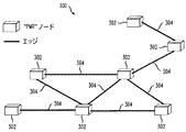
典型的な企業ネットワークは、専用のWANラインまたはトンネルを介して接続された、地理的に分散した複数のサイトを有する。各サイトはグラフGのノードと考えることができ、2つのノードを接続するWANリンクはGのエッジになる。グラフGは、2つのノード間に複数のエッジを有する多重グラフであってもよい。このグラフにおいて、例えば、図2のグラフ/ネットワーク200に示されるように、ノード202間には、経路の冗長性のための、1つまたは複数のリンク204から構成された複数の経路があり、保護用に使用されている。上記のグラフは、VoIPのオーバレイ・ネットワークを形成する。このグラフの各ノードには、本発明の原理に従って、1つまたは複数のPMRデバイスが機能として組み込まれている。結果として得られた(組み込まれたPMRを含む)グラフ/ネットワークを、オーバレイVoIP PMRグラフ/ネットワークと呼ぶ。このようなグラフ/ネットワーク300が、図3に示されている。この図では、PMRデバイスは参照番号302で示され、エッジは参照番号304で示されている。
A typical enterprise network has multiple geographically dispersed sites connected via dedicated WAN lines or tunnels. Each site can be considered as a node of the graph G, and the WAN link connecting the two nodes becomes the edge of G. The graph G may be a multiple graph having a plurality of edges between two nodes. In this graph, for example, as shown in the graph /
VoIP品質の問題は、ノードの内部でも(サイト内部の問題に起因して)起こり得るが、より一般的にはGのエッジに存在する問題に起因する(すなわち、WANリンクの問題に起因する)。各PMRは、オーバレイVoIP PMRネットワークを識別し、キープアライブ信号を複数の経路に沿って送信する。VoIPによって設けられる自然の制約(例えば、制限された遅延、ジッタなど)により、調査のために考慮すべき可能な経路が指示され制限されることになる。このような経路は一般に、例えば、VoIP配備の評価段階で見つかるはずである。各PMRは、オーバレイ・ネットワークの技術、および/またはトンネリング/アドレス書き換えの技術を使用して、パケットを「最良の」VoIP経路に沿って迂回させることができる。 VoIP quality issues can occur even within a node (due to site-internal issues), but more commonly due to issues that exist at the edge of the G (ie due to WAN link issues). . Each PMR identifies an overlay VoIP PMR network and sends keepalive signals along multiple paths. The natural constraints (eg, limited delay, jitter, etc.) imposed by VoIP will indicate and limit the possible paths to consider for the investigation. Such a route should generally be found, for example, during the evaluation phase of a VoIP deployment. Each PMR may use overlay network techniques and / or tunneling / address rewriting techniques to divert packets along the “best” VoIP path.
オーバレイVoIP PMRグラフについては、興味深いルーティングの問題が存在するが、本明細書の焦点が、オーバレイ・ネットワークおよびオーバレイ・ネットワークの構築にはないことに留意されたい。ここで注目すべきことは、VoIP接続の健全性を評価するために低帯域幅技術を使用すること、経路の選択のために「制御のための検出」パケットを選択的に複製する方法を使用すること、および判断を実行するために限定されたバージョンのオーバレイ・ネットワーク技術を使用することである。 Note that although there are interesting routing issues for the overlay VoIP PMR graph, the focus here is not on overlay networks and construction of overlay networks. Noteworthy here is the use of low-bandwidth techniques to assess the health of VoIP connections, and the method of selectively replicating “detection for control” packets for route selection. And using a limited version of overlay network technology to perform the decision.
IV.誤報確率および遅延低減
このセクションでは、ある程度数学的な詳細に立ち入り、本発明のシステムのいくつかの態様を検討する。先ず、(誤報と呼ばれている)障害が誤って宣言される確率を計算する。この解析では、VoIP有音無音モデルのいくつかの態様を採用して、M.Karol、P.Krishnan、J.J.Li、「VoIP Network Failure Detection and User Notification」、Proc.2003 Int.Conf.on Computer Communications and Networks、October 2003の場合より厳しい上限を生成する。この論文の開示を、参照により本明細書に組み込む。解析結果は、プロトタイプ実装における検出時間および誤報率の実測結果とよく一致する。ここでは、有音無音モデルのパラメータが、誤報確率にどのように影響を与えるかを示し、誤報確率、障害検出時間(kT)、およびキープアライブ・パケットが投入される割合(R=1/T)の間のいくつかのトレードオフについて論ずる。最後に、複製されたキープアライブ・パケットを使用して達成できる低減された遅延を評価して、代替の低遅延経路への高速切り換えを制御する。
IV. False alarm probability and delay reduction This section goes into some mathematical detail and considers some aspects of the system of the present invention. First, calculate the probability that a fault (called misinformation) will be incorrectly declared. In this analysis, several aspects of the VoIP voiceless silence model are adopted. Karol, P.A. Krishnan, J. et al. J. et al. Li, “VoIP Network Failure Detection and User Notification”, Proc. 2003 Int. Conf. on Computer Communications and Networks, October 2003. The disclosure of this article is incorporated herein by reference. The analysis results agree well with the actual measurement results of detection time and false alarm rate in prototype implementation. Here, it is shown how the parameters of the voiceless silence model affect the false alarm probability, the false alarm probability, the failure detection time (kT), and the rate at which keep-alive packets are inserted (R = 1 / T). ) Discuss some trade-offs. Finally, the reduced delay that can be achieved using replicated keepalive packets is evaluated to control fast switching to an alternative low delay path.
誤報は、エンドツーエンド接続がまだ動作中であるにもかかわらず、RTPパケットおよびキープアライブ・パケットが、(パケット損失またはジッタのために)時間kTの間まったく受信されなかった場合に発生する。一般に、RTPパケットは、(有音中は)キープアライブ・パケット(例えば、T=500msごとに1回)よりはるかに速いレート(例えば、20msごとに1回)で送信されるので、(典型的なパケット損失確率としては)RTP有音中には誤報は発生しないと想定しても問題ない。例えば、長さ2秒(例えば、k=4、およびT=500ms)の有音期間中に、すべてのRTPパケットが損失されたか、または遅延した場合は、障害は(ほとんど)確実に発生する(発生しない場合は、ネットワークのパケット損失レートが高すぎて、正常な状態であっても許容できるVoIP QoSを提供できないことになる)。したがって、誤報確率の計算においては、キープアライブ・パケットの損失だけに注目する。また、キープアライブ・パケットへのジッタの影響も無視する。その理由は、各キープアライブ・パケット間の間隔Tは、(許容できるVoIP QoSを提供できるほど十分に小さいことが必要な)ネットワーク・ジッタより十分に大きいからである。 A false alarm occurs when an RTP packet and keep-alive packet are not received at all for time kT (due to packet loss or jitter) even though the end-to-end connection is still operational. In general, RTP packets are transmitted at a much faster rate (eg, once every 20 ms) than keep-alive packets (eg, once every T = 500 ms) It is safe to assume that no false alarm will occur during RTP sound. For example, if all RTP packets are lost or delayed during a sound period of 2 seconds in length (eg, k = 4 and T = 500 ms), the failure will (almost) certainly occur ( If not, the packet loss rate of the network is too high to provide an acceptable VoIP QoS even under normal conditions). Therefore, in calculating the false alarm probability, we focus only on the loss of keep-alive packets. It also ignores the effect of jitter on keep-alive packets. The reason is that the interval T between each keepalive packet is sufficiently larger than the network jitter (which needs to be small enough to provide acceptable VoIP QoS).
fnは、n個のキープアライブ・パケット送信の間に、k個(または、それ以上の)連続するパケットがドロップする確率を示す(この場合、RTPストリーム中の単一の無音期間中にk個のパケットが送信された場合には、誤報が引き起こされる)。連続するキープアライブ・パケットの間隔が相対的に大きいので、各パケットは確率pで独立にドロップするものと想定する。したがって、fnは次の再帰的定義で与えられる。
fn=fn−1+(1−fn−k−1)(1−p)pk, n>k (1)
また、初期条件としてfk=pkであり、n<kの場合はfn=0である。fn−k−1≧0なので、次式が得られる。
fn<fn-1+(1−p)pk, n>k (2)
式(2)をfnについて解くと、次式が得られる。
fn<pk[(n−k+1)−(n−k)p], n>k (3)
f n indicates the probability that k (or more) consecutive packets will be dropped during the transmission of n keep-alive packets (in this case k during a single silence period in the RTP stream). A false alarm will be triggered if a single packet is sent). Since the interval between successive keepalive packets is relatively large, it is assumed that each packet drops independently with probability p. Therefore, f n is given by the following recursive definition.
f n = f n−1 + (1−f n−k−1 ) (1−p) p k , n> k (1)
Further, f k = p k as an initial condition, and f n = 0 when n <k. Since f n−k−1 ≧ 0, the following equation is obtained.
f n <f n−1 + (1−p) p k , n> k (2)
Solving equation (2) for f n yields:
f n <p k [(n−k + 1) − (n−k) p], n> k (3)
したがって、fnについての上限が得られたことになる。このfnを使用して継続時間Lの通話の間の誤報確率の上限が計算できる。各有音期間中に、少なくとも1つのRTPパケットがうまく送信されると想定したので、異なるRTP無音期間の間に損失が発生した場合は、k個の連続するキープアライブ・パケットの損失によって誤報が引き起こされることはないはずである。したがって、全体の誤報確率を計算するために、先ず、kTより長い継続期間の各RTP無音期間に対する誤報確率をそれぞれ独立に計算する(すなわち、特定の長さの無音期間の間に、k個以上の連続するキープアライブ・パケットがドロップする確率を計算する)。次いで、全通話期間にわたり、様々な無音期間の長さに従って平均化することによって、全体の誤報確率を求める。 Therefore, an upper limit for f n is obtained. Using this f n , the upper limit of the false alarm probability during a call of duration L can be calculated. Assuming that at least one RTP packet is successfully transmitted during each voiced period, if a loss occurs during different RTP silence periods, a false alarm is caused by the loss of k consecutive keepalive packets. Should not be triggered. Therefore, in order to calculate the total false alarm probability, first, the false alarm probability for each RTP silence period with a duration longer than kT is calculated independently (ie, k or more during a silence period of a specific length). The probability of dropping consecutive keep-alive packets.) The overall false alarm probability is then determined by averaging over the length of the various silence periods over the entire call period.
全体の誤報確率を計算する前に、先ず、誤報確率が、RTPの有音および無音期間の固有の確率分布に大きく依存することに留意されたい。例えば、すべてのRTP無音期間の継続期間がkT未満である場合は、(このセクションの想定の下では)誤報は発生しない。その理由は、nがk未満の場合は常に、fn = 0であり、その上限は、(すべての無音期間nがk未満のときは)誤報確率が0であることを正しく示している。同様に、有音期間の長さも(具体的には、継続時間Lの通話内で発生する無音期間の数に影響を与えることにより)全体の誤報確率に影響を与える。 Before calculating the overall false alarm probability, first note that the false alarm probability is highly dependent on the inherent probability distribution of the RTP voiced and silent periods. For example, if the duration of all RTP silence periods is less than kT, no false alarm will occur (under the assumptions in this section). The reason is that f n = 0 whenever n is less than k, and the upper limit correctly indicates that the false alarm probability is zero (when all silence periods n are less than k). Similarly, the length of a voiced period also affects the overall false alarm probability (specifically, by affecting the number of silent periods that occur within a call of duration L).
無音期間がnTと(n+1)Tの間の継続時間を有する(すなわち、その無音期間の間にn個のキープアライブ・パケットが送信される)確率を、dnによって示す。確率dnは、例えば、所与のオンオフVoIP有音無音モデルから直接計算することができる。したがって、誤報が(ランダムな)無音期間の間に発生する確率hは次式で与えられる。

最後に、m個の(統計的に独立な)無音期間を有する通話の、全体の誤報確率gmは次式で与えられる
gm=1−(1−h)m, (5)
(3)式より、[(n−k+1)−(n−k)p]<nとなるので、fn<npkであることが分かる。したがって、(4)式から次式が得られる。
gm<1−{1−pk*「Y|T」}m, (7)
Finally, the overall false alarm probability g m for a call with m (statistically independent) silence periods is given by g m = 1− (1−h) m , (5)
From the equation (3), [(n−k + 1) − (n−k) p] <n, so that f n <np k . Therefore, the following equation is obtained from the equation (4).
g m <1- {1-p k * “Y | T”} m , (7)
継続時間Lの通話の間にm個の無音期間がある確率は、個別のVoIP有音無音モデルから求めることができる。しかし、ここでは、例示(および簡単化)のために、無音期間の数mがその期待値L/(Y+X)に等しいときの誤報確率gだけを計算する。ただし、XはRTP有音期間の期待長さを表す。(7)式で、m=L/(Y+X)と設定すると、次式が得られる。
g<1−{1−pk*「Y|T」}L/(Y+X), (8)
(8)式を使用すると、誤報確率g、障害検出時間(kT)、およびキープアライブ・パケットのために必要な(割合R=1/Tに比例する)余分の帯域幅の間の、多くのトレードオフを調べることができる。個々の比較は、通話の長さL、パケット損失率p、およびRTP有音および無音期間の期待長さに依存する。例示のために、Y=X=10秒(すなわち、同じ有音および無音継続時間を有する対称的な通話)とする。表1および表2は、10分の通話、5%のパケット損失率(p=0.05)、ならびに障害検出時間(kT)をそれぞれ1秒および500ミリ秒とした場合の、いくつかの代表的な結果を示す。誤報確率gがkの増加とともに急速に低下することに留意されたい。一方、余分の「キープアライブ帯域幅」は、(検出時間が一定ならば、)kの増加とともにリニアに増加する。
The probability that there are m silence periods between calls of duration L can be determined from individual VoIP silence models. However, for the sake of illustration (and simplification), only the false alarm probability g when the number m of silent periods is equal to the expected value L / (Y + X) is calculated here. However, X represents the expected length of the RTP sound period. In the equation (7), when m = L / (Y + X) is set, the following equation is obtained.
g <1- {1- pk * "Y | T"} L / (Y + X) , (8)
Using equation (8), many of the false alarm probability g, failure detection time (kT), and extra bandwidth needed for keep-alive packets (proportional to the ratio R = 1 / T) Trade-offs can be examined. Individual comparisons depend on the call length L, the packet loss rate p, and the expected length of RTP speech and silence periods. For illustration purposes, let Y = X = 10 seconds (ie, a symmetric call with the same voice and silence duration). Tables 1 and 2 show some representatives for a 10 minute call, a 5% packet loss rate (p = 0.05), and a failure detection time (kT) of 1 second and 500 milliseconds, respectively. Results are shown. Note that the false alarm probability g decreases rapidly with increasing k. On the other hand, the extra “keep alive bandwidth” increases linearly with increasing k (if the detection time is constant).
最後に、複製されたキープアライブ・パケットを使用して代替経路のQoSを比較することに関する、いくつかの性能面について解析して、VoIP通話の最適経路への高速切り換えの制御を支援する。個別の性能向上については、代替のより良い経路が発見される割合と切り換え速度に依存する。どのような種類の性能向上が可能であるかを知るために、ここでは「即時」検出および切り換えという、極端な場合(すなわち、各パケットが、現状の最良かつ最小遅延の経路に沿って送信される場合)を考える。このようなシステムは、より広い帯域幅を犠牲にしてVoIPパケットそのものを複製することによって近似できる。その結果、各パケットの一方の複製が常に現在の最良の経路をとることになる。 Finally, some performance aspects related to comparing alternative route QoS using replicated keepalive packets are analyzed to help control the fast switching of VoIP calls to the optimal route. Individual performance improvements depend on the rate at which alternative better paths are found and the switching speed. To know what kind of performance improvement is possible, here is the extreme case of “immediate” detection and switching (ie, each packet is sent along the current best and least delay path) Think). Such a system can be approximated by replicating the VoIP packet itself at the expense of wider bandwidth. As a result, one copy of each packet will always take the current best path.
あるパケットが経路iを横断したときの遅延をXiで表す。したがって、理想は、あらゆるパケットが現在の最小遅延の経路に沿って経路制御され、結果として、パケット遅延Xが遅延Xiの最小値に等しくなることである。すなわち、デュアルホーム構成では、X=min{X1,X2}となることである。様々な遅延モデル(または、実際のネットワーク遅延測定)のために、(解析的に、または数値的に)Xの分布を決定することができる。実際のネットワーク・モデルおよびトラフィック・モデルは、解析的には非常に複雑なものであるが、簡単な遅延モデルによって、有益な見通しを提供し、いくつかの重要な性能特性およびトレードオフを明らかにする。 The delay when a packet crosses path i is denoted by X i . Therefore, the ideal is that every packet is routed along the current minimum delay path, and as a result, the packet delay X is equal to the minimum value of the delay X i . That is, in the dual home configuration, X = min {X 1 , X 2 }. The distribution of X can be determined (analytically or numerically) for various delay models (or actual network delay measurements). The actual network and traffic models are analytically very complex, but a simple delay model provides a useful perspective and reveals some important performance characteristics and tradeoffs To do.
例示のために、デュアルホーム・アーキテクチャを考える。この場合、各経路の遅延は、単純なM/M/1待ち行列の待ち時間としてモデル化される。実ネットワーク(の待ち行列)は、単純なM/M/1モデルよりはるかに複雑である。しかし、結論は定性的には同一になる。経路iに対して、1/λiは平均到達間隔、1/μiは平均サービス時間とし、全経路負荷をρi=λi/μiとする。このとき、Prob{Xi≦t}=1−ρi*e−μ i (1−ρ i )t,ただしt>0であり、Prob{Xi=0}=1−ρiである。 For illustration purposes, consider a dual home architecture. In this case, the delay of each path is modeled as the latency of a simple M / M / 1 queue. The real network (the queue) is much more complex than the simple M / M / 1 model. However, the conclusion is qualitatively the same. For path i, 1 / λ i is the average arrival interval, 1 / μ i is the average service time, and the total path load is ρ i = λ i / μ i . At this time, Prob {X i ≦ t} = 1−ρ i * e− μ i (1−ρ i ) t , where t> 0, and Prob {X i = 0} = 1−ρ i .
次に、qiが経路i上のパケット損失確率を示すものとする。また、2つの遅延分布は、(恐らくは、2つの経路が異なるサービス・プロバイダのネットワークであるために)統計的に独立であると想定する。このとき、次式が得られる。
Prob{X≦t}=1−Prob{X1>t}*Prob{X2>t}=1−{(1−q1)(1−q2)ρ1ρ2*e−μ 1 (1−ρ 1 )te−μ 2 (1−ρ 2 )t}−{(1−q1)q2ρ1*e−μ 1 (1−ρ 1 )t}−{q1(1−q2)ρ2*e−μ 2 (1−ρ 2 )t}−q1q2,(ただし、t>0) (9)
また、
Prob{X=0}=1−(1−q1)(1−q2)ρ1ρ2−(1−q1)q2ρ1−q1(1−q2)ρ2−q1q2, (10)
Next, let q i denote the packet loss probability on path i. Also assume that the two delay distributions are statistically independent (perhaps because the two paths are different service provider networks). At this time, the following equation is obtained.
Prob {X ≦ t} = 1−Prob {X 1 > t} * Prob {X 2 > t} = 1 − {(1-q 1 ) (1-q 2 ) ρ 1 ρ 2 * e −μ 1 ( 1-ρ 1) t e -μ 2 (1-ρ 2) t} - {(1-q 1)
Also,
Prob {X = 0} = 1- (1-q 1 ) (1-q 2 ) ρ 1 ρ 2- (1-q 1 ) q 2 ρ 1 -q 1 (1-q 2 ) ρ 2 -q 1 q 2 , (10)
式(9)および(10)を使用して、表3は、10%のパケット損失率(すなわち、q1=0.1)を有する経路1が、損失の無い経路2(すなわち、q2=0)と組み合わされたときの、いくつかの代表的な遅延のトレードオフを示す。表3は、様々な負荷(ρ1およびρ2)に対する遅延Xの99百分位数(すなわち、パケットの99%が表3に示された値より小さい遅延になる数)を一覧表にしたものである。表3の最後の行は、比較のために、経路1への切り換えがまったくない場合の、経路2の遅延(X2)の99百分位数を一覧にしたものである。この比較により、高速のQoS検出および代替経路への切り換えによって可能になる、遅延の低減が示される。例えば、経路2の総負荷が40%の場合、高速切り換えなしならば、遅延の99百分位数は6.2(パケット長)であり、高速切り換えを用いると、99百分位数は(表3で)2.5から5.4の範囲の値にまで低減される。遅延低減量が代替経路1の総負荷(および対応する遅延)に依存していることは明らかである。すなわち、経路1の負荷(遅延)が大きくなるにつれて、経路2から経路1へのパケットの高速切り換えによって可能な改善の量はより少なくなる。経路2の方が、経路1よりパケット損失が少ないにもかかわらず、(経路1の遅延の方が小さいときには)いくつかのパケットを経路1に切り換えることが有利である。
Using Equations (9) and (10), Table 3 shows that
V.例示的なハードウェア実装
次に図4を参照すると、ブロック図には、本発明の一実施形態による、本明細書に記載の技術の実装に適したコンピュータ・システムの一般化されたハードウェア・アーキテクチャが示されている。すなわち、コンピュータ・システム400は、サーバ、ルータ、エッジ・デバイス、および/または送信サイト(図1の102)または受信サイト(図1の104)のゲートウェイ、1つまたは複数のそれらのサイト・コンポーネントに組み込まれたPMR装置(図1の106、図3の302)もしくはリモート位置のスタンドアローンのPMR装置、本発明の原理の実装に適する任意のシステムまたは装置などを表す。当然のことながら、本発明が、特定のコンピュータ・システムへの実装に限定されるものではないことを理解されたい。
V. Exemplary Hardware Implementation Referring now to FIG. 4, a block diagram illustrates a generalized hardware diagram of a computer system suitable for implementing the techniques described herein, according to one embodiment of the invention. The architecture is shown. That is, the
この例示的な実装において、本発明の方法の少なくとも一部を実装するプロセッサ402は、バス410または代替接続装置を介して、メモリ404、入出力(I/O)装置406、およびネットワーク・インタフェース408に動作可能に結合されている。本明細書で使用する「プロセッサ」という用語が、例えば、CPU(中央演算処理装置)および/または他の処理回路(例えば、DSP(デジタル・シグナル・プロセッサ)、マイクロプロセッサ)などの任意の処理デバイスを含むことを意図したものであることを理解されたい。さらに、「プロセッサ」という用語が複数の処理デバイスを意味する場合があること、また、ある処理デバイスに関連する様々な要素は他の処理デバイスと共用できることを理解されたい。
In this exemplary implementation, a
本明細書で使用する「メモリ」という用語は、プロセッサまたはCPUに関連した、メモリおよび他のコンピュータ可読の媒体、例えば、RAM(ランダム・アクセス・メモリ)、ROM(リード・オンリー・メモリ)、固定記憶メディア(例えば、ハード・ドライブ)、リムーバブル記憶メディア(例えば、ディスケット)、フラッシュ・メモリなどを含むことを意図したものである。 As used herein, the term “memory” refers to memory and other computer-readable media associated with a processor or CPU, such as RAM (Random Access Memory), ROM (Read Only Memory), fixed It is intended to include storage media (eg, hard drives), removable storage media (eg, diskettes), flash memory, and the like.
また、本明細書で使用する「入出力装置」という用語は、処理ユニットにデータを入力するための1つまたは複数の入力装置(例えば、キーボード、マウスなど)、ならびに処理ユニットに関する結果を提供するための1つまたは複数の出力装置(例えば、CRT表示器など)を含むことを意図したものである。 Also, as used herein, the term “input / output device” provides one or more input devices (eg, keyboard, mouse, etc.) for entering data into the processing unit, as well as results relating to the processing unit. Intended to include one or more output devices (eg, a CRT display).
また、本明細書で使用する「ネットワーク・インタフェース」という用語は、例えば、コンピュータ・システム400を他のコンピュータ・システムと通信できるようにする機能を有する、1つまたは複数の装置を含むことを意図したものである。したがって、ネットワーク・インタフェースは、適切な通信プロトコルを介して、他のコンピュータ・システムの送受信機と通信するように構成された送受信機を含むことができる。本発明が、特定の通信プロトコルに限定されるものではないことを理解されたい。
Also, as used herein, the term “network interface” is intended to include one or more devices that have the capability of enabling the
本明細書では、本発明を障害検出および復旧システムの文脈で説明してきたが、本発明の方法が、コンピュータ可読媒体の形で分配できること、また、分配のために実際に使用される信号搬送媒体の個々の種類とは無関係に、本発明を実装し、その利点を実現できることを理解されたい。本明細書で使用する「コンピュータ可読媒体」という用語は、記録可能型媒体、例えば、フロッピ・ディスク、ハード・ディスク・ドライブ、RAM、CD(コンパクト・ディスク)ROM、ならびに伝送型媒体、例えば、デジタルまたはアナログ通信リンク、無線周波数伝送や光伝送などの伝送形式を使用した有線または無線通信リンクなどを含むことを意図したものである。コンピュータ可読媒体は、コード化されたフォーマットの形をとることができる。このコード化されたフォーマットは、特定のデータ処理システムでの使用時にデコードされる。 Although the present invention has been described herein in the context of a fault detection and recovery system, it should be noted that the method of the present invention can be distributed in the form of a computer readable medium and that the signal carrier medium actually used for distribution. It should be understood that the present invention can be implemented and its advantages can be realized regardless of the particular type of the. As used herein, the term “computer-readable medium” refers to recordable media such as floppy disks, hard disk drives, RAM, CD (compact disk) ROM, and transmission media such as digital. Alternatively, it is intended to include an analog communication link, a wired or wireless communication link using a transmission format such as radio frequency transmission and optical transmission. The computer readable medium may take the form of a coded format. This encoded format is decoded when used in a particular data processing system.
したがって、本明細書で説明した本発明の方法を実施するための命令またはコードを含む、1つまたは複数のコンピュータ・プログラムまたはそのソフトウェア・コンポーネントは、1つまたは複数の関連する記憶媒体(例えば、ROM、固定またはリムーバブル記憶装置)に格納することができ、使用時に、全体または一部が(例えば、RAMに)ロードされ、プロセッサ402によって実行される。
Accordingly, one or more computer programs or software components thereof, including instructions or code for performing the inventive methods described herein, may be associated with one or more associated storage media (eg, ROM, fixed or removable storage) and in use, in whole or in part (eg, in RAM) and executed by
いずれの場合でも、本明細書で説明し添付の図面に示された本発明の技術は、ハードウェア、ソフトウェア、またはそれらの組み合わせなど様々な形で実装することができる。例えば、付随するメモリ、特定実装用の集積回路、機能回路などを備えた、動作可能にプログラムされた1つまたは複数の汎用デジタルコンピュータなどに実装することができる。本明細書で提示した本発明の技術を前提とすれば、当業者なら、本発明の技術の他の実装を企図できるはずである。 In any case, the techniques of the present invention described herein and illustrated in the accompanying drawings may be implemented in various forms, such as hardware, software, or a combination thereof. For example, it can be implemented in one or more general purpose digital computers that are operatively programmed with associated memory, specific integrated circuits, functional circuits, and the like. Given the inventive techniques presented herein, one of ordinary skill in the art would be able to contemplate other implementations of the inventive techniques.
VI.例示の要約および拡張
したがって、本明細書で例示として説明してきたように、本発明は、ネットワークに固有の冗長性を使用することによって、VoIPネットワークの復旧力およびQoSを改善するための技術を提供する。本発明は、VoIPストリームに投入される、短い、低帯域幅のキープアライブ・パケットを使用して、障害およびネットワークQoS状態を高速に検出するための新しい監視技術を提供する。本発明は、制御のための監視および検出という考えを重視することによって、キープアライブ・パケットを効果的に複製して第1および第2のネットワーク経路を比較する方法を提示する。また、タイミングと同期の複雑さを避けながら、2つの経路間のQoS差をより容易に計算する方法も提示する。誤差も除去される。本明細書では、誤報確率を計算することによって、検出方法の良さを解析的に調査した。また、経路間を切り換えることの潜在的な性能利点を調査することによって、本発明の制御方式の利点も解析的に調査した。本発明の提案による解決策は、(PMRと呼ばれる)装置の中に埋め込むことができる。PMRは、メディア・ゲートウェイ、エンタープライズ・ルータ、またはエッジ・デバイスと同一場所に配置するか、またはその中に組み込むことができる。
VI. Exemplary Summary and Extension Thus, as has been described herein by way of example, the present invention provides a technique for improving resiliency and QoS of a VoIP network by using network-specific redundancy. To do. The present invention provides a new monitoring technique for fast detection of faults and network QoS conditions using short, low bandwidth keep-alive packets injected into the VoIP stream. The present invention presents a method for effectively replicating keep-alive packets and comparing the first and second network paths by emphasizing the notion of monitoring and detection for control. Also presented is a method to more easily calculate the QoS difference between two paths while avoiding timing and synchronization complexity. Errors are also eliminated. In this specification, the goodness of the detection method was analytically investigated by calculating the false alarm probability. Also, by investigating the potential performance advantages of switching between paths, the advantages of the control scheme of the present invention were also investigated analytically. The solution according to the proposal of the invention can be embedded in a device (called PMR). The PMR can be co-located or incorporated within the media gateway, enterprise router, or edge device.
本発明の原理が、他のトラフィック・タイプの性能を監視(および比較)するために使用できることを理解されたい。例えば、各ノードが、「高優先度」および「低優先度」(がヘッダに指定された)キープアライブ・パケットを投入した場合は、高優先度および低優先度サービスのジッタを測定することができる。 It should be understood that the principles of the present invention can be used to monitor (and compare) the performance of other traffic types. For example, if each node injects a “high priority” and “low priority” keepalive packet (specified in the header), the jitter of high priority and low priority services may be measured. it can.
本明細書では、本発明の例示的実施形態を添付の図面を参照して説明してきたが、本発明が、これらの実施形態そのものに限定されるものではないことを理解されたい。また、当業者なら、本発明の範囲および趣旨を逸脱することなく、様々な他の変形形態および修正形態を実施し得ることを理解されたい。 Although exemplary embodiments of the present invention have been described herein with reference to the accompanying drawings, it should be understood that the present invention is not limited to these embodiments per se. In addition, it should be understood by those skilled in the art that various other changes and modifications can be made without departing from the scope and spirit of the invention.
Claims (18)
複数のキープアライブ・パケットを、前記通信ネットワーク内のソース・ノードから前記通信ネットワーク内の宛先ノードに対して、前記ソース・ノードと前記宛先ノードとの間の、少なくとも一部が分離した2つ以上の経路を介して送信するステップであって、前記送信するステップは、前記1つまたは複数のキープアライブ・パケットを同時に送信することを含む、ステップ、及び、
前記宛先ノードで、前記1つまたは複数のキープアライブ・パケットを前記2つ以上の経路を介して受信したとき、前記宛先ノードで、前記通信ネットワークの1つまたは複数の状態を示す少なくとも1つの品質尺度を、前記2つ以上の各経路に対して計算するステップを含み、
前記2つ以上の経路の各々についての少なくとも1つの品質尺度は、(i)前記2つ以上の経路の第1の経路を介して到着する第1のキープアライブ・パケットと(ii)前記2つ以上の経路の第2の経路を介して到着する第2のキープアライブ・パケットとの間の、前記宛先ノードにおける到着時間の差にもっぱら基くことを特徴とする方法。
A method for detecting one or more states of a communication network comprising:
Two or more separate keep-alive packets at least partially separated between the source node and the destination node from a source node in the communication network to a destination node in the communication network Transmitting via the path of: comprising transmitting the one or more keep-alive packets simultaneously; and
At least one quality indicative of one or more states of the communication network at the destination node when the destination node receives the one or more keep-alive packets via the two or more paths. a measure, the step of calculating relative to the two or more respective paths seen including,
At least one quality measure for each of the two or more paths is: (i) a first keep-alive packet arriving via a first path of the two or more paths; and (ii) the two A method characterized in that it is based solely on the difference in arrival time at the destination node with a second keep-alive packet arriving via the second of the above paths .
Further comprising the method of claim 1 the step of comparing the quality measures computed for the two or more of each path.
The method of claim 2, further comprising: transmitting the comparison result from the destination node to the source node.
The method of claim 3, further comprising transmitting one or more communication packets from the source node based on at least a portion of the received result.
The method of claim 4, wherein the one or more communication packets are VoIP packets.
The method of claim 4, wherein the one or more communication packets are signaling packets.
The method of claim 2, wherein the step of comparing further comprises comparing the quality measure calculated based on the difference in arrival times at the destination node .
The method of claim 1, wherein the transmitting step further comprises transmitting the one or more keep-alive packets at regular time intervals via the two or more paths.
The transmission of claim 1, wherein the step of transmitting further comprises transmitting the one or more keep-alive packets by tunneling through one or more intermediate nodes in the communication network. the method of.
The method of claim 1, wherein the at least one quality measure is associated with one of delay, jitter, and loss.
メモリと、
前記メモリに結合された少なくとも1つのプロセッサであって、1つまたは複数のキープアライブ・パケットを、前記通信ネットワーク内のソース・ノードから前記通信ネットワーク内の宛先ノードに対して、前記ソース・ノードと前記宛先ノードの間の、少なくとも一部が分離した2つ以上の経路を介して送信するように動作し、前記宛先ノードで、前記1つまたは複数のキープアライブ・パケットが前記2つ以上の経路を介して受信されたとき、前記宛先ノードで、前記通信ネットワークの1つまたは複数の状態を示す少なくとも1つの品質尺度が、前記2つ以上の各経路に対して計算可能になるプロセッサとを含み、
前記送信は、前記1つまたは複数のキープアライブ・パケットを同時に送信することを含み、及び、
前記2つ以上の経路の各々についての少なくとも1つの品質尺度は、(i)前記2つ以上の経路の第1の経路を介して到着する第1のキープアライブ・パケットと(ii)前記2つ以上の経路の第2の経路を介して到着する第2のキープアライブ・パケットとの間の、前記宛先ノードにおける到着時間の差にもっぱら基くことを特徴とする装置。
A device used to detect one or more states of a communication network,
Memory,
At least one processor coupled to the memory, wherein one or more keep-alive packets are transmitted from a source node in the communication network to a destination node in the communication network; Operable to transmit over two or more separate paths between the destination nodes, at least in part, wherein the one or more keep-alive packets are the two or more paths And at least one quality measure indicative of one or more states of the communication network at the destination node when received via the processor, wherein the at least one quality measure is computable for each of the two or more paths. ,
The transmitting includes transmitting the one or more keep-alive packets simultaneously; and
At least one quality measure for each of the two or more paths is: (i) a first keep-alive packet arriving via a first path of the two or more paths; and (ii) the two An apparatus based solely on a difference in arrival time at the destination node with a second keep-alive packet arriving via a second route of the above routes .
The apparatus of claim 11, wherein the transmitting operation includes transmitting the plurality of keep-alive packets at regular time intervals via the two or more paths.
The apparatus of claim 11, wherein the transmitting operation includes transmitting the one or more keep-alive packets by tunneling through one or more intermediate nodes in the communication network. .
メモリと、
前記メモリに結合された少なくとも1つのプロセッサであって、1つまたは複数のキープアライブ・パケットが、前記通信ネットワーク内のソース・ノードから前記通信ネットワーク内の宛先ノードに対して、前記ソース・ノードと前記宛先ノードの間の、少なくとも一部が分離した2つ以上の経路を介して送信されたことに応答して、前記宛先ノードにて、前記1つまたは複数のキープアライブ・パケットを前記2つ以上の経路を介して受信したとき、前記宛先ノードで、前記通信ネットワークの1つまたは複数の状態を示す少なくとも1つの品質尺度を、前記2つ以上の各経路に対して計算するように動作するプロセッサとを含み、
前記送信は、前記少なくとも1つまたは複数のキープアライブ・パケットを同時に送信することを含み、及び、
前記2つ以上の経路の各々についての少なくとも1つの品質尺度は、(i)前記2つ以上の経路の第1の経路を介して到着する第1のキープアライブ・パケットと(ii)前記2つ以上の経路の第2の経路を介して到着する第2のキープアライブ・パケットとの間の、前記宛先ノードにおける到着時間の差にもっぱら基くことを特徴とする装置。
A device used to detect one or more states of a communication network,
Memory,
At least one processor coupled to the memory, wherein one or more keepalive packets are transmitted from a source node in the communication network to a destination node in the communication network; In response to being transmitted over two or more separate paths at least partially between the destination nodes, the two or more keep-alive packets are transmitted at the destination node. When received via the above paths, the destination node operates to calculate at least one quality measure indicative of one or more states of the communication network for each of the two or more paths Including a processor,
The transmitting includes transmitting the at least one or more keep-alive packets simultaneously; and
At least one quality measure for each of the two or more paths is: (i) a first keep-alive packet arriving via a first path of the two or more paths; and (ii) the two An apparatus based solely on a difference in arrival time at the destination node with a second keep-alive packet arriving via a second route of the above routes .
The apparatus of claim 14, wherein the at least one processor is further operative to compare the quality measures calculated for each of the two or more paths.
The apparatus of claim 15, wherein the at least one processor is further operative to send a result of a prior comparison from the destination node to the source node.
The apparatus of claim 15, wherein the comparing operation further comprises comparing the quality measure calculated based on the difference in arrival times at the destination node .
Applications Claiming Priority (2)
| Application Number | Priority Date | Filing Date | Title |
|---|---|---|---|
| US58132904P | 2004-06-18 | 2004-06-18 | |
| US10/953,024 US7782787B2 (en) | 2004-06-18 | 2004-09-29 | Rapid fault detection and recovery for internet protocol telephony |
Publications (3)
| Publication Number | Publication Date |
|---|---|
| JP2006005942A JP2006005942A (en) | 2006-01-05 |
| JP2006005942A5 JP2006005942A5 (en) | 2006-11-24 |
| JP4625377B2 true JP4625377B2 (en) | 2011-02-02 |
Family
ID=35071112
Family Applications (1)
| Application Number | Title | Priority Date | Filing Date |
|---|---|---|---|
| JP2005177179A Expired - Fee Related JP4625377B2 (en) | 2004-06-18 | 2005-06-17 | Fast failure detection and recovery for Internet protocol phones |
Country Status (5)
| Country | Link |
|---|---|
| US (1) | US7782787B2 (en) |
| EP (1) | EP1610496B1 (en) |
| JP (1) | JP4625377B2 (en) |
| CA (1) | CA2508545C (en) |
| DE (1) | DE602005010940D1 (en) |
Families Citing this family (67)
| Publication number | Priority date | Publication date | Assignee | Title |
|---|---|---|---|---|
| US7664043B1 (en) | 2004-07-01 | 2010-02-16 | At&T Corp. | Method and apparatus for performing reachability testing within the context of customer virtual private networks |
| US7768997B2 (en) * | 2004-08-20 | 2010-08-03 | At&T Intellectual Property I, L.P. | Systems and methods for automatic public switched telephone network backup of voice over internet protocol services |
| US7466656B2 (en) * | 2004-10-26 | 2008-12-16 | International Business Machines Corporation | Method, apparatus and program storage device for efficient construction of network overlays through interconnection topology embedding |
| US7440393B2 (en) * | 2004-12-09 | 2008-10-21 | Scalent Systems, Inc. | Method and system for managing communication in a data network |
| US8462637B1 (en) * | 2005-01-04 | 2013-06-11 | Sheridan Ross P.C. | Dial plan routing for fragmented networks |
| US7978682B2 (en) * | 2005-05-09 | 2011-07-12 | At&T Intellectual Property I, Lp | Methods, systems, and computer-readable media for optimizing the communication of data packets in a data network |
| US7590756B2 (en) * | 2005-05-13 | 2009-09-15 | Itt Manufacturing Enterprises, Inc. | Method and system for transferring data in a communications network using redundant communication paths |
| US20060268848A1 (en) * | 2005-05-25 | 2006-11-30 | Telefonaktiebolaget Lm Ericsson (Publ) | Connection type handover of voice over internet protocol call based low-quality detection |
| US8107385B2 (en) | 2005-09-29 | 2012-01-31 | Avaya Inc. | Evaluating quality of service in an IP network with cooperating relays |
| CN100403734C (en) * | 2005-11-02 | 2008-07-16 | 华为技术有限公司 | Business flor protection method |
| US7596092B2 (en) * | 2006-02-02 | 2009-09-29 | Cisco Technology, Inc. | VoIP verifier |
| US8072879B2 (en) * | 2006-02-03 | 2011-12-06 | Cisco Technology, Inc. | Technique for determining whether to reestablish fast rerouted primary tunnels based on backup tunnel path quality feedback |
| US8693308B2 (en) | 2006-02-10 | 2014-04-08 | Aviat U.S., Inc. | System and method for resilient wireless packet communications |
| JP4545109B2 (en) * | 2006-03-28 | 2010-09-15 | 京セラ株式会社 | Communication path control device |
| JP4356705B2 (en) * | 2006-03-31 | 2009-11-04 | 日本電気株式会社 | Computer system and earthquake response system |
| US7813736B2 (en) * | 2006-06-28 | 2010-10-12 | At&T Intellectual Property I, L.P. | Method and apparatus for improving network performance in a communication system |
| US8630190B2 (en) | 2006-08-22 | 2014-01-14 | Cisco Technology, Inc. | Method and system to identify a network device associated with poor QoS |
| US8055759B2 (en) * | 2006-09-18 | 2011-11-08 | Tropos Networks, Inc. | Determination of link qualities between an access point and a plurality of clients |
| US8391154B2 (en) | 2006-09-28 | 2013-03-05 | Avaya Inc. | Probationary admission control in relay networks |
| US7697460B2 (en) | 2006-09-28 | 2010-04-13 | Avaya Inc. | Evaluating feasible transmission paths in a packet network |
| JP4675305B2 (en) * | 2006-09-29 | 2011-04-20 | 富士通株式会社 | Network optimal route selection method and apparatus |
| US9374263B2 (en) * | 2006-09-29 | 2016-06-21 | Avaya Ecs Ltd. | Latency differential mitigation for real time data streams |
| US7787450B1 (en) * | 2006-10-11 | 2010-08-31 | Itt Manufacturing Enterprises, Inc | Method and system for efficient network formation and maintenance of node routing databases in a mobile ad-hoc network |
| US8576833B2 (en) * | 2006-12-15 | 2013-11-05 | At&T Intellectual Property I, L.P. | Fault tolerant voice over Internet protocol (VoIP) systems and methods to operate the same |
| KR101290275B1 (en) * | 2007-01-16 | 2013-08-07 | 삼성전자주식회사 | Apparatus and method for transporting and receiving graphic data |
| JP2008211682A (en) * | 2007-02-27 | 2008-09-11 | Fujitsu Ltd | Reception program, transmission program, transmission/reception system, and transmission/reception method |
| CN100512154C (en) * | 2007-03-29 | 2009-07-08 | 华为技术有限公司 | A method and device for improving the multi-layer network service recovery performance |
| US7756029B2 (en) * | 2007-05-24 | 2010-07-13 | Harris Stratex Networks Operating Corporation | Dynamic load balancing for layer-2 link aggregation |
| US9455896B2 (en) | 2007-07-23 | 2016-09-27 | Verint Americas Inc. | Dedicated network interface |
| US8264953B2 (en) * | 2007-09-06 | 2012-09-11 | Harris Stratex Networks, Inc. | Resilient data communications with physical layer link aggregation, extended failure detection and load balancing |
| US8233402B2 (en) * | 2007-09-20 | 2012-07-31 | At&T Intellectual Property Ii, L.P. | Multicast-based inference of temporal loss characteristics in packet data networks |
| US20090086642A1 (en) * | 2007-09-28 | 2009-04-02 | Cisco Technology, Inc. | High availability path audit |
| US8099637B2 (en) * | 2007-10-30 | 2012-01-17 | Hewlett-Packard Development Company, L.P. | Software fault detection using progress tracker |
| US7768947B2 (en) * | 2007-12-31 | 2010-08-03 | International Business Machines Corporation | Maintaining communication continuity |
| US7886014B2 (en) * | 2007-12-31 | 2011-02-08 | International Business Machines Corporation | Maintaining communication continuity |
| US7821923B2 (en) | 2008-02-06 | 2010-10-26 | Cellco Partnership | Optimized SIP routing architecture using an integrated network and systems approach |
| US20090296703A1 (en) * | 2008-05-30 | 2009-12-03 | Ruby Tech Corp. | Method and system for dynamic roaming across wireless networks |
| US8125907B2 (en) * | 2008-06-12 | 2012-02-28 | Talari Networks Incorporated | Flow-based adaptive private network with multiple WAN-paths |
| US8130752B2 (en) | 2008-06-13 | 2012-03-06 | Telco Acquisition I, Inc. | Real-time network measurement |
| US7903579B2 (en) * | 2008-08-26 | 2011-03-08 | International Business Machines Corporation | Self-optimization and self-healing of voice quality problems utilizing service oriented architecture |
| US20100124211A1 (en) * | 2008-11-17 | 2010-05-20 | Qualcomm Incorporated | Reducing an occurrence of a voip call on hold from being dropped in ev-do systems |
| JP4937235B2 (en) * | 2008-11-21 | 2012-05-23 | 株式会社東芝 | Remote monitoring system and fault isolation method |
| US10333808B2 (en) | 2009-06-11 | 2019-06-25 | Talari Networks Incorporated | Methods and apparatus for providing adaptive private network centralized management system data visualization processes |
| EP2302845B1 (en) | 2009-09-23 | 2012-06-20 | Google, Inc. | Method and device for determining a jitter buffer level |
| JP5352502B2 (en) * | 2010-03-05 | 2013-11-27 | 株式会社日立製作所 | Packet communication system and packet communication apparatus control method |
| US8339970B2 (en) * | 2010-04-02 | 2012-12-25 | Clearwire IP Holdings | System and method for network optimization |
| EP2559192A4 (en) * | 2010-04-15 | 2017-10-04 | Vonage Network LLC | Systems and methods of improving the quality of voip communications |
| US8630412B2 (en) | 2010-08-25 | 2014-01-14 | Motorola Mobility Llc | Transport of partially encrypted media |
| US8477050B1 (en) | 2010-09-16 | 2013-07-02 | Google Inc. | Apparatus and method for encoding using signal fragments for redundant transmission of data |
| FR2966674A1 (en) * | 2010-10-22 | 2012-04-27 | France Telecom | Method for transmission of data flow between e.g. radio emitter/receiver and radio access controller, involves detecting absence of transmission of information relative to operating state of managing equipment, and transmitting data stream |
| US8838680B1 (en) | 2011-02-08 | 2014-09-16 | Google Inc. | Buffer objects for web-based configurable pipeline media processing |
| EP2611075B1 (en) * | 2011-04-21 | 2018-01-24 | Huawei Technologies Co., Ltd. | Fault detection method and system |
| GB2494385B (en) | 2011-08-31 | 2018-06-06 | Metaswitch Networks Ltd | Transmitting and forwarding data |
| US9806835B2 (en) * | 2012-02-09 | 2017-10-31 | Marvell International Ltd. | Clock synchronization using multiple network paths |
| US8854954B2 (en) * | 2012-04-24 | 2014-10-07 | International Businesss Machines Corporation | Quality of service prediction and call failover |
| US20150046558A1 (en) * | 2013-03-15 | 2015-02-12 | Google Inc. | System and method for choosing lowest latency path |
| US9769058B2 (en) * | 2013-05-17 | 2017-09-19 | Ciena Corporation | Resilient dual-homed data network hand-off |
| US9203936B2 (en) * | 2013-10-07 | 2015-12-01 | At&T Intellectual Property I, Lp | Method and apparatus for initiating communication sessions |
| KR102109610B1 (en) * | 2013-10-29 | 2020-05-12 | 에스케이플래닛 주식회사 | Terminal Equipment and Call service system based Internet Protocol |
| WO2015075763A1 (en) * | 2013-11-21 | 2015-05-28 | 富士通株式会社 | Information processing system, information processing device, and data communication method |
| GB2532072B (en) * | 2014-11-07 | 2017-04-19 | Canon Kk | Feedback management in a multipath communication network |
| US10439908B2 (en) | 2014-12-23 | 2019-10-08 | Talari Networks Incorporated | Methods and apparatus for providing adaptive private network centralized management system time correlated playback of network traffic |
| JP6443173B2 (en) | 2015-03-27 | 2018-12-26 | 富士通株式会社 | Video data processing apparatus, video data processing system, video data processing method, and video data processing program |
| US10200435B2 (en) * | 2015-09-22 | 2019-02-05 | Pathsolutions, Inc. | Network communications service quality monitor |
| US10812601B2 (en) * | 2017-03-07 | 2020-10-20 | Flash Networks Ltd. | Method and system for signaling and radio connection optimization over a cellular network |
| US11736406B2 (en) * | 2017-11-30 | 2023-08-22 | Comcast Cable Communications, Llc | Assured related packet transmission, delivery and processing |
| JP7121845B1 (en) | 2021-09-29 | 2022-08-18 | Kddi株式会社 | Terminal device and display method |
Citations (6)
| Publication number | Priority date | Publication date | Assignee | Title |
|---|---|---|---|---|
| JP2002044125A (en) * | 2000-07-19 | 2002-02-08 | Nippon Telegr & Teleph Corp <Ntt> | Packet network |
| JP2002176441A (en) * | 2000-12-08 | 2002-06-21 | Fujitsu Ltd | Communication unit |
| US20020150041A1 (en) * | 2001-03-07 | 2002-10-17 | Onetier Communications, Inc. | Method and system for providing an improved quality of service for data transportation over the internet |
| JP2003258902A (en) * | 2002-02-28 | 2003-09-12 | Hitachi Communication Technologies Ltd | Method for detecting line state of ip network and ip communication device |
| JP2004007361A (en) * | 2001-10-11 | 2004-01-08 | Nippon Telegr & Teleph Corp <Ntt> | Method for controlling data transmission, program therefor, and data transmission apparatus employing the same |
| JP2004159146A (en) * | 2002-11-07 | 2004-06-03 | Nippon Telegr & Teleph Corp <Ntt> | Communication network and packet transfer device |
Family Cites Families (12)
| Publication number | Priority date | Publication date | Assignee | Title |
|---|---|---|---|---|
| JP2723097B2 (en) * | 1995-12-04 | 1998-03-09 | 日本電気株式会社 | QOS routing device |
| WO1998041041A1 (en) * | 1997-03-12 | 1998-09-17 | Alcatel Network Systems, Inc. | Telecommunications network distributed restoration method and system |
| US20030133417A1 (en) * | 1997-03-12 | 2003-07-17 | Sig H. Badt | Method and message therefor of monitoring the spare capacity of a dra network |
| US20020004843A1 (en) * | 2000-07-05 | 2002-01-10 | Loa Andersson | System, device, and method for bypassing network changes in a routed communication network |
| US6853641B2 (en) * | 2000-12-20 | 2005-02-08 | Nortel Networks Limited | Method of protecting traffic in a mesh network |
| US20020093948A1 (en) * | 2001-01-16 | 2002-07-18 | Motorola, Inc. | Packet-based multimedia communications system having one or more wireless links |
| US6895441B1 (en) * | 2001-07-30 | 2005-05-17 | Atrica Ireland Ltd. | Path rerouting mechanism utilizing multiple link bandwidth allocations |
| US20030061340A1 (en) * | 2001-09-25 | 2003-03-27 | Mingqiu Sun | Network health monitoring through real-time analysis of heartbeat patterns from distributed agents |
| US7032131B2 (en) * | 2002-03-26 | 2006-04-18 | Hewlett-Packard Development Company, L.P. | System and method for ensuring merge completion in a storage area network |
| TWI254527B (en) * | 2003-02-19 | 2006-05-01 | Nec Corp | Network system, spanning tree configuration method and spanning tree configuration node |
| US7043250B1 (en) * | 2003-04-16 | 2006-05-09 | Verizon Corporate Services Group Inc. | Systems and methods for forming and operating a communications network |
| KR100645428B1 (en) * | 2003-05-05 | 2006-11-15 | 삼성전자주식회사 | Apparatus and method for establishment of routing path in wpan |
-
2004
- 2004-09-29 US US10/953,024 patent/US7782787B2/en active Active
-
2005
- 2005-05-27 CA CA2508545A patent/CA2508545C/en not_active Expired - Fee Related
- 2005-06-13 EP EP05253643A patent/EP1610496B1/en not_active Expired - Fee Related
- 2005-06-13 DE DE602005010940T patent/DE602005010940D1/en active Active
- 2005-06-17 JP JP2005177179A patent/JP4625377B2/en not_active Expired - Fee Related
Patent Citations (6)
| Publication number | Priority date | Publication date | Assignee | Title |
|---|---|---|---|---|
| JP2002044125A (en) * | 2000-07-19 | 2002-02-08 | Nippon Telegr & Teleph Corp <Ntt> | Packet network |
| JP2002176441A (en) * | 2000-12-08 | 2002-06-21 | Fujitsu Ltd | Communication unit |
| US20020150041A1 (en) * | 2001-03-07 | 2002-10-17 | Onetier Communications, Inc. | Method and system for providing an improved quality of service for data transportation over the internet |
| JP2004007361A (en) * | 2001-10-11 | 2004-01-08 | Nippon Telegr & Teleph Corp <Ntt> | Method for controlling data transmission, program therefor, and data transmission apparatus employing the same |
| JP2003258902A (en) * | 2002-02-28 | 2003-09-12 | Hitachi Communication Technologies Ltd | Method for detecting line state of ip network and ip communication device |
| JP2004159146A (en) * | 2002-11-07 | 2004-06-03 | Nippon Telegr & Teleph Corp <Ntt> | Communication network and packet transfer device |
Also Published As
| Publication number | Publication date |
|---|---|
| DE602005010940D1 (en) | 2008-12-24 |
| EP1610496B1 (en) | 2008-11-12 |
| CA2508545C (en) | 2011-03-29 |
| CA2508545A1 (en) | 2005-12-18 |
| US7782787B2 (en) | 2010-08-24 |
| JP2006005942A (en) | 2006-01-05 |
| US20050281204A1 (en) | 2005-12-22 |
| EP1610496A1 (en) | 2005-12-28 |
Similar Documents
| Publication | Publication Date | Title |
|---|---|---|
| JP4625377B2 (en) | Fast failure detection and recovery for Internet protocol phones | |
| US20070286351A1 (en) | Method and System for Adaptive Media Quality Monitoring | |
| US8254557B2 (en) | Supervisor intercept for teleagent voice over internet protocol communications | |
| US7843842B2 (en) | Method and system for initiating a remote trace route | |
| US8929382B2 (en) | Method, device, and computer program product for detecting and encoding states for accurate measurement | |
| US6868094B1 (en) | Method and apparatus for measuring network data packet delay, jitter and loss | |
| KR100571191B1 (en) | Packet network monitoring system and method | |
| US8804575B2 (en) | Central entity to adjust redundancy and error correction on RTP sessions | |
| KR101260237B1 (en) | Method and apparatus for providing end-to-end high quality services based on performance characterizations of network conditions | |
| US8107385B2 (en) | Evaluating quality of service in an IP network with cooperating relays | |
| US8248953B2 (en) | Detecting and isolating domain specific faults | |
| US9866610B2 (en) | Methods, systems, and computer readable media for selecting a codec pair based on network conditions | |
| CA2656500A1 (en) | Method and system for network path discrimination | |
| US8184546B2 (en) | Endpoint device configured to permit user reporting of quality problems in a communication network | |
| JP2004297287A (en) | Call quality evaluation system, and apparatus for call quality evaluation | |
| US9509744B2 (en) | Systems and methods of routing IP telephony data packet communications | |
| EP1414187A1 (en) | Method for evaluating the quality of service of a telecommunication link via a network | |
| US7630308B1 (en) | Systems and methods for applying a variable encoding/decoding scheme in a communication network | |
| Fitzpatrick et al. | An approach to transport layer handover of VoIP over WLAN. | |
| US7525952B1 (en) | Method and apparatus for determining the source of user-perceived voice quality degradation in a network telephony environment | |
| Rajendran et al. | Performance optimization of VoIP using an overlay network | |
| US7958386B2 (en) | Method and apparatus for providing a reliable fault management for a network | |
| Karol et al. | Rapid fault detection and recovery for IP telephony | |
| Sousa et al. | REF: Resilience evaluation framework | |
| US8055755B2 (en) | Method for determining VoIP gateway performance and SLAs based upon path measurements |
Legal Events
| Date | Code | Title | Description |
|---|---|---|---|
| A521 | Written amendment |
Free format text: JAPANESE INTERMEDIATE CODE: A523 Effective date: 20061005 |
|
| A621 | Written request for application examination |
Free format text: JAPANESE INTERMEDIATE CODE: A621 Effective date: 20061005 |
|
| A977 | Report on retrieval |
Free format text: JAPANESE INTERMEDIATE CODE: A971007 Effective date: 20090423 |
|
| A131 | Notification of reasons for refusal |
Free format text: JAPANESE INTERMEDIATE CODE: A131 Effective date: 20090427 |
|
| A521 | Written amendment |
Free format text: JAPANESE INTERMEDIATE CODE: A523 Effective date: 20090723 |
|
| A131 | Notification of reasons for refusal |
Free format text: JAPANESE INTERMEDIATE CODE: A131 Effective date: 20090817 |
|
| A601 | Written request for extension of time |
Free format text: JAPANESE INTERMEDIATE CODE: A601 Effective date: 20091117 |
|
| A602 | Written permission of extension of time |
Free format text: JAPANESE INTERMEDIATE CODE: A602 Effective date: 20091120 |
|
| A521 | Written amendment |
Free format text: JAPANESE INTERMEDIATE CODE: A523 Effective date: 20100120 |
|
| A02 | Decision of refusal |
Free format text: JAPANESE INTERMEDIATE CODE: A02 Effective date: 20100323 |
|
| A521 | Written amendment |
Free format text: JAPANESE INTERMEDIATE CODE: A523 Effective date: 20100723 |
|
| A911 | Transfer to examiner for re-examination before appeal (zenchi) |
Free format text: JAPANESE INTERMEDIATE CODE: A911 Effective date: 20100730 |
|
| TRDD | Decision of grant or rejection written | ||
| A01 | Written decision to grant a patent or to grant a registration (utility model) |
Free format text: JAPANESE INTERMEDIATE CODE: A01 Effective date: 20101012 |
|
| A01 | Written decision to grant a patent or to grant a registration (utility model) |
Free format text: JAPANESE INTERMEDIATE CODE: A01 |
|
| A61 | First payment of annual fees (during grant procedure) |
Free format text: JAPANESE INTERMEDIATE CODE: A61 Effective date: 20101105 |
|
| R150 | Certificate of patent or registration of utility model |
Free format text: JAPANESE INTERMEDIATE CODE: R150 |
|
| FPAY | Renewal fee payment (event date is renewal date of database) |
Free format text: PAYMENT UNTIL: 20131112 Year of fee payment: 3 |
|
| LAPS | Cancellation because of no payment of annual fees |