JP4625016B2 - Commutators for electrical equipment - Google Patents
Commutators for electrical equipment Download PDFInfo
- Publication number
- JP4625016B2 JP4625016B2 JP2006540297A JP2006540297A JP4625016B2 JP 4625016 B2 JP4625016 B2 JP 4625016B2 JP 2006540297 A JP2006540297 A JP 2006540297A JP 2006540297 A JP2006540297 A JP 2006540297A JP 4625016 B2 JP4625016 B2 JP 4625016B2
- Authority
- JP
- Japan
- Prior art keywords
- interference
- commutator
- contact bridge
- contact
- elements
- Prior art date
- Legal status (The legal status is an assumption and is not a legal conclusion. Google has not performed a legal analysis and makes no representation as to the accuracy of the status listed.)
- Expired - Fee Related
Links
Images


Classifications
-
- H—ELECTRICITY
- H01—ELECTRIC ELEMENTS
- H01R—ELECTRICALLY-CONDUCTIVE CONNECTIONS; STRUCTURAL ASSOCIATIONS OF A PLURALITY OF MUTUALLY-INSULATED ELECTRICAL CONNECTING ELEMENTS; COUPLING DEVICES; CURRENT COLLECTORS
- H01R39/00—Rotary current collectors, distributors or interrupters
- H01R39/02—Details for dynamo electric machines
- H01R39/04—Commutators
-
- H—ELECTRICITY
- H01—ELECTRIC ELEMENTS
- H01R—ELECTRICALLY-CONDUCTIVE CONNECTIONS; STRUCTURAL ASSOCIATIONS OF A PLURALITY OF MUTUALLY-INSULATED ELECTRICAL CONNECTING ELEMENTS; COUPLING DEVICES; CURRENT COLLECTORS
- H01R39/00—Rotary current collectors, distributors or interrupters
- H01R39/02—Details for dynamo electric machines
- H01R39/46—Auxiliary means for improving current transfer, or for reducing or preventing sparking or arcing
- H01R39/54—Auxiliary means for improving current transfer, or for reducing or preventing sparking or arcing by use of impedance between brushes or segments
-
- H—ELECTRICITY
- H01—ELECTRIC ELEMENTS
- H01R—ELECTRICALLY-CONDUCTIVE CONNECTIONS; STRUCTURAL ASSOCIATIONS OF A PLURALITY OF MUTUALLY-INSULATED ELECTRICAL CONNECTING ELEMENTS; COUPLING DEVICES; CURRENT COLLECTORS
- H01R39/00—Rotary current collectors, distributors or interrupters
-
- H—ELECTRICITY
- H01—ELECTRIC ELEMENTS
- H01R—ELECTRICALLY-CONDUCTIVE CONNECTIONS; STRUCTURAL ASSOCIATIONS OF A PLURALITY OF MUTUALLY-INSULATED ELECTRICAL CONNECTING ELEMENTS; COUPLING DEVICES; CURRENT COLLECTORS
- H01R39/00—Rotary current collectors, distributors or interrupters
- H01R39/02—Details for dynamo electric machines
- H01R39/04—Commutators
- H01R39/06—Commutators other than with external cylindrical contact surface, e.g. flat commutators
-
- H—ELECTRICITY
- H02—GENERATION; CONVERSION OR DISTRIBUTION OF ELECTRIC POWER
- H02K—DYNAMO-ELECTRIC MACHINES
- H02K11/00—Structural association of dynamo-electric machines with electric components or with devices for shielding, monitoring or protection
- H02K11/02—Structural association of dynamo-electric machines with electric components or with devices for shielding, monitoring or protection for suppression of electromagnetic interference
- H02K11/028—Suppressors associated with the rotor
-
- H—ELECTRICITY
- H02—GENERATION; CONVERSION OR DISTRIBUTION OF ELECTRIC POWER
- H02K—DYNAMO-ELECTRIC MACHINES
- H02K13/00—Structural associations of current collectors with motors or generators, e.g. brush mounting plates or connections to windings; Disposition of current collectors in motors or generators; Arrangements for improving commutation
- H02K13/10—Arrangements of brushes or commutators specially adapted for improving commutation
- H02K13/105—Spark suppressors associated with the commutator
-
- Y—GENERAL TAGGING OF NEW TECHNOLOGICAL DEVELOPMENTS; GENERAL TAGGING OF CROSS-SECTIONAL TECHNOLOGIES SPANNING OVER SEVERAL SECTIONS OF THE IPC; TECHNICAL SUBJECTS COVERED BY FORMER USPC CROSS-REFERENCE ART COLLECTIONS [XRACs] AND DIGESTS
- Y10—TECHNICAL SUBJECTS COVERED BY FORMER USPC
- Y10T—TECHNICAL SUBJECTS COVERED BY FORMER US CLASSIFICATION
- Y10T29/00—Metal working
- Y10T29/49—Method of mechanical manufacture
- Y10T29/49002—Electrical device making
- Y10T29/49009—Dynamoelectric machine
- Y10T29/49011—Commutator or slip ring assembly
Landscapes
- Engineering & Computer Science (AREA)
- Power Engineering (AREA)
- Physics & Mathematics (AREA)
- Electromagnetism (AREA)
- Motor Or Generator Current Collectors (AREA)
- Current-Collector Devices For Electrically Propelled Vehicles (AREA)
- Rectifiers (AREA)
- Dc Machiner (AREA)
Abstract
Description
この発明は、絶縁性の成形材料から形成された支持部材と、その上に整流子軸を中心にして均等配置された複数の金属製導体セグメントおよびその上に配置された回転子巻線用の接続要素と、ならびに前記導体セグメントと導電的に接続された混信防止装置とからなり、混信防止装置が導体セグメントの数に相当する数の整流子軸を中心にして配置された個別の混信防止要素と、対応する導体セグメントと導電性に結合されるとともに互いに隣接する各2つの混信防止要素を導電性に相互に結合しかつ前記対応する導体セグメントと導電性に結合する、前記数と同数の接触ブリッジとを備えた、電気機器用の整流子に関する。 The present invention relates to a support member formed of an insulating molding material, a plurality of metal conductor segments equally arranged around a commutator axis thereon, and a rotor winding disposed thereon An individual interference preventing element comprising a connecting element and an interference preventing device conductively connected to the conductor segment, wherein the interference preventing device is arranged around a number of commutator axes corresponding to the number of conductor segments. And the same number of contacts that are conductively coupled to and adjacent to each other and are adjacent to each other and electrically conductively coupled to the corresponding conductor segments. The present invention relates to a commutator for an electric device including a bridge.
異なった構成形式(ドラム型整流子、平形整流子)の整流子が多様な構成形態によって知られている。特にドラム型整流子としての構成形態において、その整流子を備えている電気機械の近傍に設置された電子部品群が整流子上の電波生成によって影響を受けることを防止するために、電波抑制装置(混信防止装置)を装備した整流子が増えている。 Commutators of different configuration types (drum type commutator, flat type commutator) are known in various configurations. In particular, in a configuration form as a drum-type commutator, in order to prevent an electronic component group installed in the vicinity of an electric machine including the commutator from being affected by radio wave generation on the commutator, a radio wave suppression device The number of commutators equipped with (interference prevention devices) is increasing.
この種の混信防止装置は、従来電圧依存型抵抗を有する材料からなるリング形状の混信防止盤として構成されることが知られており、これは導体セグメントと導電的に接続されている。該当する混信防止盤は、ブラシ滑走面の放射方向外側(例えば、米国特許第5895990A号明細書、米国特許第5717270A号明細書、英国特許出願公開第2183933A号明細書、ならびに米国特許第5796203A号明細書参照)に配置するか、あるいはブラシ滑走面の放射方向内側(例えば、米国特許第6285106B1号明細書、独国特許出願公開第19953231A1号明細書参照)に配置することができる。加えて、導体セグメントが外側のシリンダ状混信防止スリーブ上に配置されている混信防止された特殊形式のドラム型整流子が知られている(独国特許第2055648号公報ならびに独国特許3614869C2号明細書)。欧州特許第364292B1号明細書には、接続ラグの半径方向下側に混信防止被覆を有するかあるいは独立した混信防止リングが隣接して配置された耐熱性の補強リングが設けられた熱可塑性材料から形成された支持部材を有するドラム型整流子が記載されており;この補強リングは必要に応じて設けられる独立した混信防止リングと同様に支持部材の台座上に配置されており、そこで導体セグメントから突出している固定リンクによって支持されている。 It is known that this kind of interference prevention device is conventionally configured as a ring-shaped interference prevention board made of a material having a voltage-dependent resistance, which is conductively connected to a conductor segment. Appropriate anti-interference boards are provided radially outside the brush sliding surface (e.g. U.S. Pat. No. 5,895,990A, U.S. Pat. No. 5,717,270A, U.K. Patent Publication No. 2183933A, and U.S. Pat. No. 5,796,203A). Or in the radial inside of the brush running surface (see, for example, US Pat. No. 6,285,106 B1, DE-A-1995 3231 A1). In addition, there is known a special type of drum-type commutator in which a conductor segment is arranged on an outer cylindrical interference prevention sleeve, in which interference is prevented (German Patent No. 2055648 and German Patent No. 3614869C2) book). EP 364292 B1 describes a thermoplastic material provided with a heat-resistant reinforcing ring which has an anti-interference coating on the lower side of the connecting lug in the radial direction or an adjacent anti-interference ring arranged adjacently. A drum-type commutator having a formed support member is described; this reinforcing ring is arranged on a pedestal of the support member in the same way as an independent anti-interference ring provided where necessary, from the conductor segment. It is supported by a protruding fixed link.
混信防止盤の個別の構成とは無関係に、混信防止装置が環形状の混信防止盤からなる全ての整流子において、混信防止装置の多大なコストが問題点となる。これは、通常この種の混信防止盤を形成するために使用するセラミック材料が極めて高価であるためであり;また多層式金属−セラミック盤から切削して環形状の混信防止盤を製造する際には大量の切削屑が発生する。 Regardless of the individual configuration of the crosstalk prevention panel, the great cost of the crosstalk prevention apparatus becomes a problem in all commutators in which the crosstalk prevention apparatus is a ring-shaped crosstalk prevention board. This is because the ceramic material normally used to form this kind of anti-interference board is very expensive; and when making a ring-shaped anti-interference board by cutting from a multilayer metal-ceramic board A large amount of cutting waste is generated.
加えて、多くの実用上の適用に際して整流子が使用できる空間が限られているため、混信防止盤を使用して混信防止する既知のドラム型整流子のうちブラシ滑走面の半径方向内側に配置された混信防止盤を有する小型の整流子のみが使用可能である。ブラシ滑走面の放射方向内側に配置された混信防止リングを有するこの種のドラム型整流子の別の問題点は、通常セラミック材料から形成される混信防止盤と該当する整流子のその他の構成要素と比べて異なった熱特性によるものである。特別な処置が施されない限り、熱応力によって破損した混信防止盤および/または導体セグメントと混信防止盤との間の接続の破壊のため早期の整流子の故障が発生し得る。この問題を解決するため、独国特許出願公開第19953231A1号明細書においては、可塑性の接着剤を使用して混信防止盤を支持部材に接合し導体セグメントは細い線を介して混信防止盤に接続し、この線は一方で該当する導体セグメントの接続ラグにハンダ付けし他方で該当する混信防止盤の金属化ゾーンにハンダ付けすることが提案されている。これに対して、前述した種類のドラム型整流子を開示している米国特許第6285106B1号明細書によれば、導体セグメントを混信防止盤と電気的に接触させるために板バネが設けられており、これは支持部材と導体セグメントと環状蓋部材によって仕切られるとともにその中にさらに混信防止盤も収容されている環状中空部内に配置されている。板バネは混信防止盤とその他の整流子構成部分において異なった放射方向の熱膨張に対応するものであり、これは特に環状蓋部材上に固定することができる。 In addition, the space where the commutator can be used for many practical applications is limited, so it is located on the radially inner side of the brush running surface among the known drum type commutators that use the anti-interference board to prevent interference. Only a small commutator having an anti-interference board can be used. Another problem with this type of drum-type commutator having an anti-interference ring disposed radially inward of the brush running surface is that the anti-interference panel, usually formed of ceramic material, and other components of the commutator in question This is due to the different thermal characteristics. Unless special measures are taken, premature commutator failures may occur due to crosstalk prevention boards and / or broken connections between conductor segments and crosstalk prevention boards that are damaged by thermal stress. In order to solve this problem, German Patent Application Publication No. 19953231A1 uses a plastic adhesive to join the anti-interference board to the support member and connect the conductor segment to the anti-interference board via a thin line. On the one hand, it has been proposed that this line be soldered to the connection lug of the relevant conductor segment and on the other hand to the metallization zone of the relevant anti-interference board. In contrast, according to U.S. Pat. No. 6,285,106 B1, which discloses a drum-type commutator of the type described above, a leaf spring is provided for electrically contacting the conductor segment with the anti-interference board. These are arranged in an annular hollow portion that is partitioned by a support member, a conductor segment, and an annular lid member, and in which an anti-interference board is also accommodated. The leaf springs correspond to different radial thermal expansions in the anti-interference board and other commutator components, which can be fixed in particular on the annular lid member.
前述した導体セグメントの放射方向内側に配置された混信防止盤を備えた両方のドラム型整流子において特に問題なことは、ドラム型整流子の競争力を低下させる高い製造コストであり、これは特に混信防止盤の高い製造コスト(上記参照)によるものである。 Of particular concern in both drum-type commutators with anti-interference boards arranged radially inward of the conductor segments described above is the high manufacturing cost that reduces the competitiveness of the drum-type commutator, especially This is due to the high manufacturing cost of the crosstalk prevention panel (see above).
従って、本発明の目的は、前述した従来の技術の観点から、少ない製造労力をもって低コストに大量生産することに向いていて、長寿命かつ信頼性の高い前述した種類の混信防止された整流子を提供することであり、この際混信防止されていない同様な設計の整流子と実質的に同等な寸法からなる混信防止された整流子を製造し得ることが好適である。 Accordingly, the object of the present invention is to provide a long-life and highly reliable commutator of the type described above that is suitable for mass production at low cost with a small manufacturing effort from the viewpoint of the above-described conventional technology. In this case, it is preferable that an anti-interference commutator having substantially the same dimensions as a commutator of a similar design that is not anti-interference can be manufactured.
前記の課題は、本発明に従って、接触ブリッジはいずれも内側に指向するとともに周囲方向において相互に接近するよう弾性を有していて両方の対応する混信防止要素と導電的に結合された2本の翼部と外側方向を指向していて対応する導体セグメントと導電的に結合された基底部とを備え、ここで接触ブリッジはその翼部領域において対応する混信防止要素と、その基底部領域においては対応する導体セグメントとハンダ付けあるいは接着結合されることによって解決される。 Two foregoing problems, according to the present invention, contact touching bridge which is mutually have elasticity both of the corresponding interference prevention element and conductively coupled to approach in the peripheral direction with directed inwardly none And a base portion conductively coupled to a corresponding conductor segment , wherein the contact bridge has a corresponding anti-interference element in the wing region and a base portion in the base region. Is solved by soldering or adhesive bonding with the corresponding conductor segments.
従って、本発明に係る整流子の第1の特徴は、混信防止装置が環状の混信防止盤を備えておらず、むしろ導体セグメントの数に相当する数の個別の混信防止要素を備えていることであり;この種の混信防止要素は多層式コンデンサとして特に四角形に形成することができ、これは多層金属−セラミック板から特に多量の切り屑を発生させることなく低コストに製造することができる。さらに、本発明に係る整流子は、各2つの互いに隣接する混信防止要素がいずれも1つの接触ブリッジを介して相互に導電性に結合され、この際接触ブリッジはその両方の翼部上で前記2つの混信防止要素と導電性に結合され、この両方の翼部が周囲方向において互いに接近するように弾力的に形成されることを特徴とする。ここで“弾力的”とは、接触ブリッジを周囲方向において変形させるために必要な応力が接触ブリッジと混信防止要素との間の結合の強度よりも小さいことを意味している。本発明に係る整流子の特徴である混信防止装置はこの方式によって混信防止要素と接触ブリッジとから構成され、これらは環状構造を構成するために交互に配置されている。ここで接触ブリッジの弾力性によって環状構造が硬直的とならないことがもたらされ;むしろこの環状構造はその周囲全域にわたって弾力的なものとなり、それによって熱膨張に従った整流子の寸法変化を補償することができる。接触ブリッジを分割された部品として製造することによって、混信防止装置の環状構造の弾力性および剛性、ならびに接触ブリッジと混信防止要素との間の接続の観点において材料の選択および寸法を最適化することによって、殆ど制限なく所要の機能に適合させることができる。 Therefore, the first feature of the commutator according to the present invention is that the interference preventing device does not include an annular interference preventing panel, but rather includes a number of individual interference preventing elements corresponding to the number of conductor segments. This kind of anti-interference element can be formed in particular as a multilayer capacitor, in particular in a square shape, which can be produced at low cost without generating a particularly large amount of chips from the multilayer metal-ceramic plate. Furthermore, the commutator according to the present invention is such that each two adjacent anti-interference elements are both conductively coupled to each other via a contact bridge, wherein the contact bridge is said on both wings. It is characterized in that it is electrically conductively coupled with two anti-interference elements, both of which are elastically formed so as to approach each other in the circumferential direction. “Resilient” here means that the stress required to deform the contact bridge in the circumferential direction is less than the strength of the coupling between the contact bridge and the anti-interference element. The interference preventing device, which is a feature of the commutator according to the present invention, is constituted by the interference preventing element and the contact bridge by this method, and these are alternately arranged to constitute an annular structure. Here, the elasticity of the contact bridge results in the annular structure not being rigid; rather, the annular structure is elastic throughout its surroundings, thereby compensating for the commutator dimensional change following thermal expansion. can do. By optimizing the material selection and dimensions in terms of the elasticity and rigidity of the annular structure of the anti-interference device and the connection between the contact bridge and the anti-interference element by manufacturing the contact bridge as a separate part Can be adapted to the required function with almost no restrictions.
組み立て状態での接触ブリッジの変形性はその弾力的な構成と並んで、接触ブリッジの翼部が自由に支持される、すなわち一般的な整流子の温度膨張の枠内で隣接する整流子の構成部材によって妨害されることなく変形可能であることによって可能になる。 The deformability of the contact bridge in the assembled state, along with its elastic configuration, allows the wings of the contact bridge to be freely supported, i.e. the configuration of the adjacent commutator within the frame of the general commutator temperature expansion This is made possible by being deformable without being obstructed by the member.
本発明によれば、接触ブリッジが単純なハンダ結合あるいは導電性の接着剤結合によって接触点の領域において恒久的に混信防止要素と結合されることである。同様なことが、導体セグメントと接触する接触ブリッジの基底領域における接触ブリッジと導体セグメントの間の結合にも該当する。この点に関して、混信防止要素の接触極の領域および/または接触ブリッジの翼部領域に適宜な金属化(例えば銀あるいは錫メッキ)を施すことが好適であり;また接触ブリッジを銅、真鍮、あるいはそれらの金属を含んだ合金から形成することも有効である。この種の接触ブリッジと混信防止要素および/または導体セグメントとの間の恒久的な結合は、混信防止要素自体と同様に周囲方向において弾力性である接触ブリッジの構成によって極少ない機械的負荷に曝されるだけであり、これは本発明に係る整流子を腐食し易い環境で使用する際に極めて効果的であることが理解される。According to the invention, the contact bridge is permanently connected to the anti-interference element in the region of the contact point by a simple solder bond or a conductive adhesive bond. The same applies to the coupling between the contact bridge and the conductor segment in the base region of the contact bridge in contact with the conductor segment. In this regard, it is preferred to apply an appropriate metallization (eg silver or tin plating) to the contact pole area of the crosstalk element and / or the wing area of the contact bridge; and the contact bridge to be copper, brass, or It is also effective to form an alloy containing these metals. The permanent coupling between this kind of contact bridge and the anti-interference element and / or conductor segment is subject to very little mechanical load by the construction of the contact bridge which is elastic in the circumferential direction as well as the anti-interference element itself. It is understood that this is extremely effective when the commutator according to the present invention is used in a corrosive environment.
本発明の枠内において、接触ブリッジと各2つの隣接する混信防止要素の接触極あるいは接触面との間の“導電性の結合”は、機械的な応力の伝達も可能なものであることが重要である。ここで、整流子の寿命に悪影響を及ぼさない、接触ブリッジと混信防止要素との間の直接的な接触は、接触ブリッジが個々の整流子構成部材の多様な熱膨張特性を補償するように変形可能であることによって達成される。 Within the framework of the present invention, the “conductive coupling” between the contact bridge and the contact pole or contact surface of each two adjacent anti-interference elements may be capable of transmitting mechanical stress. is important. Here, direct contact between the contact bridge and the anti-interference element that does not adversely affect the life of the commutator is modified so that the contact bridge compensates for the various thermal expansion characteristics of the individual commutator components. Achieved by being possible.
従って、本発明の適用により、本発明に係る整流子の特徴の組み合わせのため、最小限の加工労力により極めて低コスト、超寿命かつ小型の混信防止された整流子を製造することができる。この際、本発明はブラシ滑走面の構成に左右されずに多様な整流子構成方式に適用可能である。自動車の燃料ポンプの駆動に使用されるような、炭素材滑走面を備えた整流子を本発明に従って構成することが特に好適である。 Therefore, by applying the present invention, because of the combination of the features of the commutator according to the present invention, it is possible to manufacture a commutator that is extremely low cost, has a long service life, and is small in size, with minimal processing effort. In this case, the present invention can be applied to various commutator configuration methods regardless of the configuration of the brush sliding surface. It is particularly preferred that a commutator with a carbon material running surface, such as that used to drive an automobile fuel pump, be constructed according to the present invention.
本発明に係る整流子の別の構成形態によれば、混信防止要素は四角形の多層コンデンサとして構成され、等辺多角形の縁部に沿って整流子軸を中心に、好適にはそれぞれ隣接する2つの導体セグメント間の間隙部に配置される。このことによって製造方法が簡略化され、従って本発明に係る整流子の製造コストが低下する。 According to another configuration of the commutator according to the present invention, the interference preventing element is configured as a rectangular multilayer capacitor, and is preferably adjacent to each other around the commutator axis along the edge of the equilateral polygon. Arranged in the gap between the two conductor segments. This simplifies the manufacturing method and thus reduces the manufacturing cost of the commutator according to the invention.
接触ブリッジの構造形態に関し、本発明の枠内において大きな許容範囲がもたらされ、これを利用して特に整流子の構造様式、寸法、および固有の要求性能に対応することができる。この点に関して、本発明の第1の好適な構成形態は、接触ブリッジがいずれも場所的に2つの隣接する混信防止要素の間に配置されるとともに、当該混信防止要素の端面側接触面と結合されることが好適である。ここで、接触ブリッジはいずれも湾曲した金属製の帯状材から形成され、ここで接触ブリッジの基本形は実質的にV字型とすることができる。 With regard to the structure of the contact bridge, great tolerances are provided within the framework of the present invention, which can be used in particular to accommodate the commutator structure, dimensions and inherent performance requirements. In this regard, the first preferred configuration of the present invention is that the contact bridge is located between two adjacent crosstalk prevention elements both in place and coupled to the end face side contact face of the crosstalk prevention element. It is preferred that Here, all of the contact bridges are formed of a curved metal strip, and the basic shape of the contact bridge can be substantially V-shaped.
本発明の別の好適な構成形態によれば、接触ブリッジは混信防止要素に対して軸方向に変位した面内に配置され、側方に形成された接触面の領域で当該混信防止要素と結合される。この場合、接触ブリッジはその形状の点に関して蹄鉄とそれに結合された足部に似たものとなり、これは金属製の平板材料(例えば金板)から極めて低コストに製造することができる。この種の接触ブリッジの構成によっても、本発明に係る整流子の製造に関して好適な効果をもたらすことができる。 According to another preferred embodiment of the invention, the contact bridge is arranged in a plane axially displaced with respect to the anti-interference element and is coupled to the anti-interference element in the region of the contact surface formed on the side. Is done. In this case, the contact bridge resembles a horseshoe and a foot connected to it in terms of its shape, which can be manufactured at a very low cost from a metal flat material (eg a gold plate). This type of contact bridge configuration can also provide a favorable effect with respect to the manufacture of the commutator according to the present invention.
本発明の基盤となる概念は多様な形式の整流子(ドラム型整流子、平形整流子)ならびに多様な方式で形成されたブラシ滑走面(例えば直接金属製の導体セグメント上に形成されたもの、あるいは炭素材滑走面を有するもの等)において利点をもたらすが、シリンダ形状のブラシ滑走面を有するドラム型整流子としての整流子の構成の場合に本発明によって達成される利点が特に顕著に現れる。これは、ブラシ滑走面が軸方向に向かって混信防止装置から突出して延在するため、本発明によって極めて小型の構造が達成されるためである。 The concepts underlying the present invention are various types of commutators (drum commutators, flat commutators) as well as brush running surfaces formed in various ways (eg directly formed on metal conductor segments, The advantage achieved by the present invention is particularly noticeable in the case of a commutator configuration as a drum-type commutator having a cylinder-shaped brush sliding surface. This is because a very small structure is achieved by the present invention because the brush sliding surface extends from the crosstalk prevention device in the axial direction.
接続要素の構成の観点において、さらに別の本発明の好適な追加構成は、整流子をドラム型整流子として構成した際に混信防止装置の反対側の整流子の端面の領域に配置される接続ラグとして接続要素を形成することを特徴とする。この場合、回転子巻線の接続ラグへの溶着中において接触ブリッジと導体セグメントならびに混信防止要素との間の接続が破損する危険性が最小限となる。 In view of the configuration of the connecting element, still another preferred additional configuration of the present invention is a connection arranged in the region of the end face of the commutator on the opposite side of the interference prevention device when the commutator is configured as a drum-type commutator. The connecting element is formed as a lug. In this case, the risk of breakage of the connection between the contact bridge and the conductor segment and the anti-interference element during the welding of the rotor winding to the connection lug is minimized.
混信防止要素は、組立て中にその位置を保持するために支持部材内に軸方向に没入されている収容部内に挿入することが特に好適である。この種の収容部の仕切り壁は該当する混信防止要素を放射方向、周囲方向ならびに軸方向において向かい側の混信防止要素の放射方向内側および外側表面ならびに前端面に対して支持するように作用する。この収容部は、放射方向内側および周囲方向に対してそれぞれリブリングによってまた放射方向外側に対して支持部材の成形材突出部によって仕切ることが特に好適である。 It is particularly preferred that the anti-interference element is inserted into a receiving part that is axially immersed in the support member in order to maintain its position during assembly. The partition wall of this type of housing acts to support the corresponding interference preventing element against the radially inner and outer surfaces and the front end face of the opposite interference preventing element in the radial, circumferential and axial directions. It is particularly preferable that the housing portion is partitioned by rib rings for the radially inner side and the circumferential direction, respectively, and by a molding material protrusion of the support member for the radially outer side.
これに関連して、前述した接触ブリッジの構成の場合いずれにしても、空間的に互いに隣接する混信防止要素の間において混信防止要素の個々の収容部が接触ブリッジの取り付け空間を通じて互いに結合され、ここで取り付け空間の構成は接触ブリッジの形状に相当するものとなる。このことは必要不可欠なものではないが、接触ブリッジが前述したように混信防止要素から軸方向に変位した平面内に配置されるとともに当該混信防止要素と側面において、すなわち軸方向に形成された接触面を介して結合されている場合には極めて好適である。 In this connection, in any case of the contact bridge configuration described above, the individual accommodating portions of the interference prevention elements are coupled to each other through the attachment space of the contact bridge between the interference prevention elements spatially adjacent to each other. Here, the configuration of the mounting space corresponds to the shape of the contact bridge. Although this is not indispensable, the contact bridge is arranged in a plane displaced axially from the interference prevention element as described above, and the contact formed on the side face with the interference prevention element, that is, in the axial direction. It is very suitable when it is connected via a surface.
本発明に係る整流子の製造に関して述べると、これは、当業者において既知である方式に従って、支持部材とその中に埋入された導体セグメントからなる整流子未加工材によって形成される。この点に関して本発明は従来からよく知られた技術に基づいたものであり、従ってより詳細な説明は省略する。既知の整流子の製造に使用される技術と異なった点は、支持部材の製造に際してその端面側に設けられた混信防止要素の収容部と、ならびに必要に応じてこれらの収容部を互いに結合している接触ブリッジのための取り付け空間を形成することである。通常、これに続く個々の混信防止要素ならびにそれと同数の接触ブリッジの組み立ては前後する独立したステップで実施される。この点に関して、後続する製造プロセス中においてまず予加工された混信防止要素を前記収容部内に挿入し;これに続いて予加工された接触ブリッジをいずれも隣接する2つの混信防止要素ならびに1つの導体セグメントと導電性に結合するように取り付ける。このため接触ブリッジはその翼部の領域において対応する両方の混信防止要素と、その基底部領域において対応する胴体セグメントとハンダ付けあるいは接着することができる。 With regard to the manufacture of the commutator according to the present invention, this is formed by a commutator raw material comprising a support member and a conductor segment embedded therein, in a manner known to those skilled in the art. In this regard, the present invention is based on a conventionally well-known technique, and therefore a more detailed description is omitted. The difference from the technology used in the manufacture of the known commutator is that, when the support member is manufactured, the interference prevention element accommodating portion provided on the end face side thereof, and these accommodating portions are coupled to each other as necessary. Forming a mounting space for the contact bridge. The subsequent assembly of the individual anti-interference elements as well as the same number of contact bridges is usually carried out in separate steps. In this regard, during the subsequent manufacturing process, first a pre-processed anti-interference element is inserted into the housing; this is followed by two adjacent anti-interference elements as well as one conductor. Attached so as to be conductively connected to the segment. Thus, the contact bridge can be soldered or glued to both corresponding anti-interference elements in its wing region and to the corresponding fuselage segment in its base region.
ここで、接触ブリッジを取り付ける前に、後に混信防止要素ならびに導体セグメントと導電性に結合される部分にハンダ材あるいは接着剤を塗布することが好適である。 Here, before attaching the contact bridge, it is preferable to apply a solder material or an adhesive to the cross-talk prevention element and the portion to be conductively connected to the conductor segment.
前述したように、接触ブリッジが平板上の帯状板金材から打ち抜き加工される場合、その打ち抜き加工中の形状が製造する整流子内における形状に相当することが好適である。接触ブリッジはそれを帯状板金材から打ち抜いた後再びその中に嵌め込まれ、従ってこの帯状板金材が接触ブリッジの組み立て補助材を形成する。混信防止要素を収容部内に挿入した後、全ての接触ブリッジが同時に帯状板金材から押出すことによって(存在する場合)取り付け空間内に取り付けられる。この方式において、ハンダ材あるいは接着剤を使用する場合、接触ブリッジを再び帯状板金材内に挿入した後に、この接触ブリッジにハンダ材あるいは接着剤を塗布する。 As described above, when the contact bridge is punched from a strip-shaped sheet metal material on a flat plate, it is preferable that the shape during the punching corresponds to the shape in the commutator to be manufactured. The contact bridge is punched out of the strip sheet metal and then reinserted therein, so that the strip sheet metal forms an assembly aid for the contact bridge. After inserting the anti-interference element into the receiving part, all the contact bridges are mounted in the mounting space by simultaneously extruding (if present) from the strip sheet metal. In this system, when a solder material or an adhesive is used, the contact bridge is inserted into the strip-shaped sheet metal again, and then the solder material or the adhesive is applied to the contact bridge.
次に、本発明の実施例につき、添付図面を参照しながら以下詳細に説明する。 Next, embodiments of the present invention will be described in detail with reference to the accompanying drawings.
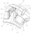
図1ないし図3に示されているドラム型整流子は、主要な構成部材として絶縁性の成形材から形成された支持部材1と整流子軸2の周りに均等に配置された10個の導体セグメント3とを備え、この導体セグメントの周囲面がブラシ滑走面4を定義している。支持部材1は軸2と同心である孔部5を備えており、これは整流子の構成において図示されていない回転子軸として機能する。
The drum-type commutator shown in FIGS. 1 to 3 has ten conductors uniformly arranged around a
導体セグメント3の電機子部分6は支持部材1の成形材料内に埋め込まれ、これによって導体セグメントが高い回転数においてもその際発生する慣性力にもかかわらず安定的に固定される。導体セグメント3の末端側には接続ラグ7が設けられており、これは既知のものと同様な方式で巻線を整流子へ接続するよう機能する。
The
前述した範囲内において図1ないし図3に示された整流子は従来の技術によるものと同様であり、従ってその詳細な説明は省略する。 Within the above-mentioned range, the commutator shown in FIGS. 1 to 3 is the same as that of the prior art, and therefore detailed description thereof is omitted.
接続ラグ7の反対側の端面8の領域内において整流子は混信防止装置9を備えている。これは等しい形状で整流子軸2の周りに配置されたセラミック材料製の10個の四角形の個別混信防止要素10ならびに10個の接触ブリッジ11からなる。ここで混信防止要素10は導体セグメント3間の間隙に配置される。これらはいずれもコンデンサ機能を有していて、(整流子を組み立てた状態で周囲方向において)互いに対向する2つの端面上にこの混信防止要素の接触極を形成する金属化層12を備えている。各混信防止要素10は、支持部材1の袋状収容部14内に収容されている。この収容部14は放射方向内側ならびに周囲方向において周囲面15または支持部材1の一部であるリブリング17の2つのリブ16によって仕切られており;放射方向外側に対してはそれぞれ支持部材1の成形材突出部18が混信防止要素10の収容部14を仕切っている。各成形材突出部18上には外側に2つの導体セグメント3が着合しており;各2つの隣接する導体セグメント3を互いに絶縁している空隙部19は成形材突出部18内部へ延在している。
In the region of the end face 8 on the opposite side of the
接触ブリッジ11は、それぞれ空間的に隣接する2つの混信防止要素10の間に配置され、当該混信防止要素と端面側の接触極13の領域で結合される。これはいずれも金属製帯状材からなり、これが2つの翼部20と1つの基底部21を形成するために幾度も曲折される(図3)。この観点から、接触ブリッジの基本形状はV字型とされる。接触ブリッジ11を複数回曲折するため、一方で翼部21が四角形の混信防止要素10の接触極13上に大面積で接合し、他方で接触ブリッジ11は周囲方向および放射方向の両方において弾力的な柔軟性を備えることができる。接触ブリッジ11は翼部20の領域内においてハンダ付け接合部22を介して混信防止要素10と、基底部21の領域においてはハンダ付け接合部23を介して対応する導体セグメント3の半径方向内側面と固定的に結合される。混信防止要素10の収容部14は接触ブリッジ11の取り付け空間24を介して互いに結合されており、これは接触ブリッジ11の自由な変形性を妨害しないように形成されている。
The
図4ないし図6に示されている本発明に係る整流子の第2の実施例はその主要な構成要素の観点から図1ないし図3に示された実施例と同等である。従って、説明の繰り返しを避けるために前述した説明を参考にする。 The second embodiment of the commutator according to the invention shown in FIGS. 4 to 6 is equivalent to the embodiment shown in FIGS. 1 to 3 in terms of its main components. Therefore, the above-mentioned explanation is referred to in order to avoid repeated explanation.
図4ないし図6に示された整流子は、図1ないし図3に示された整流子と比べて、主に混信防止装置9′の構成が異なっている。ここで接触ブリッジ11′は平坦な金属製平板材から形成されており;接触ブリッジ11′の形状は両方の翼部20′を形成している蹄鉄状部材とその頂点に設けられた基底部21′に相当している。接触ブリッジ11′は、四角形の混信防止要素10′に対して軸方向に変位して配置され、ここでその翼部20′が混信防止要素10′に対してその側部領域で、すなわち整流子の軸方向面内に配置された金属製の接触面25′に接合している。そこにおいて接触ブリッジ11′は、ハンダ付け接合部26を介して混信防止要素10′と固定的に結合されている。導体セグメント3はいずれもその内側に溝形状の低没部27を備えており、その中に対応する接触ブリッジ11′がその基底部21′をもって嵌合する。低没部27の内側端部上には当該接触ブリッジ11′のための台座27aが形成されている。ハンダ付け接合部28によって各接触ブリッジ11′と導体セグメント3が固定的に結合されている。
The commutator shown in FIGS. 4 to 6 is mainly different from the commutator shown in FIGS. 1 to 3 in the configuration of the interference prevention device 9 ′. Here, the contact bridge 11 'is formed from a flat metal plate; the shape of the contact bridge 11' is a horseshoe-like member forming both wings 20 'and a base 21 provided at the apex thereof. It corresponds to ′. The contact bridge 11 'is arranged axially displaced with respect to the square anti-interference element 10', where its wing 20 'is in its side region with respect to the anti-interference element 10', ie the commutator. It is joined to a metal contact surface 25 'disposed in the axial plane of the metal. Therein, the
この実施例においても、混信防止要素10′のための収容部14′が接触ブリッジ11′の取り付け空間24′を介して互いに結合されており、ここで接触ブリッジの取り付け空間24′は混信防止要素10′と接触ブリッジ11′の軸方向の積重ね構成のため混信防止要素10′の収容部14′よりも小さな深さを有している。
Also in this embodiment, the
前述したドラム型整流子の実施例は勿論本発明に従って平型整流子にも適用することが可能である。その実施例が図7に示されている。ここで平型整流子は、既知の方式で、成形材から形成された支持部材1″とその中に埋め込まれた8個の導体セグメント3″を備えている。各導体セグメント3″に対してそれぞれ1つの炭素材セグメント29が導電性に結合されており、ここで炭素材セグメントの端面がブラシ滑走面4″を定義している。接続ラグ7″は整流子のブラシ滑走面4″と反対側の面の導体セグメント3″上に配置されている。
The embodiment of the drum-type commutator described above can of course be applied to a flat commutator according to the present invention. An example of this is shown in FIG. Here, the flat commutator is provided with a supporting
同様に、ブラシ滑走面4″と反対側の面上に、整流子が混信防止装置9″を備えている。これは8個の実質的に四角形の混信防止要素10″と8個の接触ブリッジ11″とを備えており、これらはいずれも両方の隣接している混信防止要素10″ならびに対応する導体セグメント3″と導電性に結合されている。混信防止要素10″は支持部材1″内に形成された収容部14″内に挿入されている。接触ブリッジ11″は取り付け空間24″内に挿入されており、これはいずれも隣接する2つの収容部14″を互いに結合しているが、収容部14″に比べて混信防止要素10″の分だけ縮小された深さを有している。その他の点では、図7に示されている平型整流子によって実現された混信防止装置は図4ないし図6に示されたドラム型整流子によって実現された混信防止装置と同様に構成されている。説明の重複を避けるために前述した整流子と同様な記述は省略する。そのことは整流子の製造方法についても同様である。
Similarly, the commutator is provided with a crosstalk prevention device 9 ″ on the surface opposite to the
Claims (22)
接触ブリッジ(11,11′,11″)はいずれも内側に指向するとともに周囲方向において相互に接近し得るような弾力性を有していて対応する両方の混信防止要素と導電的に結合された2本の翼部(20,20′)と外側方向を指向していて対応する導体セグメントと導電的に結合された基底部(21,21′)とを備えており、ここで接触ブリッジ(11,11′,11″)はその翼部(20,20′)領域において対応する混信防止要素(10,10′,10″)と、その基底部(21,21′,21″)領域においては対応する導体セグメント(3,3″)とハンダ付けあるいは接着結合される、
ことを特徴とする整流子。A support member (1,1 ″) formed of an insulating molding material, and a plurality of metals equally arranged around the commutator shaft (2) on the radially outer side of the support member (1,1 ″) Ltd. conductor segments (3, 3 ') and the conductor segments (3, 3' and connecting elements for the rotor winding diameter disposed outwardly of), and conductively with the conductor segments (3, 3 ') The anti-interference device (9, 9 ', 9 ") connected to the antenna, and the anti-interference device (9, 9', 9") corresponds to the number of conductor segments (3, 3 "). An individual anti-interference element (10, 10 ', 10 ") arranged about the axis (2) and two anti-interference elements (10 , 10 ', 10 ") are electrically coupled to each other and the corresponding conductors Binding to segment and conductive, the same number of contact bridges (11, 11 ', 11 ") and provided with a commutator for electrical equipment,
The contact bridges (11, 11 ', 11 ") are both inwardly directed and elastic so that they can approach each other in the circumferential direction and are conductively coupled to both corresponding anti-interference elements. It comprises two wings (20, 20 ') and a base (21, 21') directed outwardly and electrically coupled to the corresponding conductor segment, where the contact bridge (11 , 11 ', 11 ") in the wing (20, 20') region corresponding interference prevention elements (10, 10 ', 10") and in the base (21, 21', 21 ") region. Soldered or adhesively bonded to the corresponding conductor segment (3,3 "),
A commutator characterized by that.
複数の混信防止要素(10,10′,10″)を製造し、
それぞれ互いに接近し得るように柔軟性を有した2本の翼部(20,20′)と1つの基底部(21,21′)を備えた、混信防止要素の数と等しい数の接触ブリッジ(11,11′,11″)を製造し、
混信防止要素(10,10′,10″)を支持部材(1,1″)の収容部(14,14′,14″)内に挿入し、
接触ブリッジ(11,11′,11″)をその翼部(20,20′)領域において対応する混信防止要素(10,10′,10″)と、その基底部(21,21′)領域においては対応する導体セグメント(3,3″)とハンダ付けあるいは接着結合することによってこの接触ブリッジ(11,11′,11″)をいずれも2つの隣接する混信防止要素(10,10′,10″)ならびに1つの導体セグメント(3,3″)と導電性に結合するようにして取り付ける、
各ステップからなる整流子の製造方法。A receiving part (14, 10 ', 10 ") for an anti-interference element (10, 10', 10") arranged in the support member on the end face side, including a support member (1, 1 ") and a conductor segment (3, 3") 14 ′, 14 ″) with commutator raw material ,
Producing a plurality of interference prevention elements (10, 10 ', 10 ") ,
A number of contact bridges equal to the number of anti-interference elements, each having two wings (20, 20 ') and one base (21, 21') that are flexible so that they can approach each other. 11, 11 ', to produce a 11 "),
Inserting the interference preventing element (10, 10 ', 10 ") into the receiving part (14, 14', 14") of the support member (1, 1 ") ,
Contact bridges (11, 11 ', 11 ") in their wing (20, 20') region corresponding anti-interference elements (10, 10 ', 10") and in their base (21, 21') region Each of the contact bridges (11, 11 ', 11 ") by soldering or adhesively bonding to the corresponding conductor segments (3, 3"), and two adjacent anti-interference elements (10, 10', 10 "). ) As well as one conductor segment (3,3 ") in a conductive connection .
A commutator manufacturing method comprising each step.
Applications Claiming Priority (2)
| Application Number | Priority Date | Filing Date | Title |
|---|---|---|---|
| DE10354220A DE10354220A1 (en) | 2003-11-20 | 2003-11-20 | Commutator for an electric machine |
| PCT/EP2004/013004 WO2005050820A1 (en) | 2003-11-20 | 2004-11-17 | Commutator for an electric machine |
Publications (2)
| Publication Number | Publication Date |
|---|---|
| JP2007511997A JP2007511997A (en) | 2007-05-10 |
| JP4625016B2 true JP4625016B2 (en) | 2011-02-02 |
Family
ID=34609150
Family Applications (1)
| Application Number | Title | Priority Date | Filing Date |
|---|---|---|---|
| JP2006540297A Expired - Fee Related JP4625016B2 (en) | 2003-11-20 | 2004-11-17 | Commutators for electrical equipment |
Country Status (14)
| Country | Link |
|---|---|
| US (1) | US7462972B2 (en) |
| EP (1) | EP1685640B1 (en) |
| JP (1) | JP4625016B2 (en) |
| KR (1) | KR20060103511A (en) |
| CN (1) | CN100578896C (en) |
| AT (1) | ATE513352T1 (en) |
| BR (1) | BRPI0416761A (en) |
| DE (1) | DE10354220A1 (en) |
| HK (1) | HK1094486A1 (en) |
| MX (1) | MXPA06004291A (en) |
| RU (1) | RU2340993C2 (en) |
| TW (1) | TWI289966B (en) |
| UA (1) | UA88452C2 (en) |
| WO (1) | WO2005050820A1 (en) |
Families Citing this family (9)
| Publication number | Priority date | Publication date | Assignee | Title |
|---|---|---|---|---|
| CN101924315B (en) * | 2009-06-16 | 2014-09-03 | 德昌电机(深圳)有限公司 | Commutator and manufacturing method thereof |
| JP5899408B2 (en) * | 2011-08-01 | 2016-04-06 | パナソニックIpマネジメント株式会社 | Commutator and motor using the commutator |
| WO2013145009A1 (en) * | 2012-03-29 | 2013-10-03 | 三菱電機株式会社 | Commutator with snubber circuit and producing method |
| DE102012014218A1 (en) * | 2012-07-18 | 2014-01-23 | Brose Fahrzeugteile GmbH & Co. Kommanditgesellschaft, Würzburg | Commutator for rotor of e.g. electromotor, has contact element projecting into front-sided aperture between support structure and slats in axial direction such that slats are electrically contacted with contact element by press contact |
| DE102013109960A1 (en) * | 2012-09-12 | 2014-03-13 | Johnson Electric S.A. | Brushed motor commutator with spark suppression and manufacturing process |
| KR101585604B1 (en) * | 2015-07-01 | 2016-01-14 | 주식회사 아모텍 | Circuit protection contactor and mobile electronic device with the same |
| CN105429415B (en) * | 2015-12-23 | 2018-12-18 | 中电电机股份有限公司 | A kind of commutating pole structure |
| CN105958296B (en) * | 2016-06-24 | 2019-08-20 | 浙江利丰电器股份有限公司 | Copper segment |
| CN107332399A (en) * | 2017-06-30 | 2017-11-07 | 温州市圣帕电子科技有限公司 | A kind of motor power commutator |
Family Cites Families (11)
| Publication number | Priority date | Publication date | Assignee | Title |
|---|---|---|---|---|
| DE2055648B2 (en) | 1970-11-12 | 1972-09-28 | Fa. C. Conradty, 8500 Nürnberg | VOLTAGE-DEPENDENT COLLECTOR FOR SMALL OR SMALL MOTORS AND THE PROCESS FOR ITS MANUFACTURING |
| JPH058789Y2 (en) | 1985-05-02 | 1993-03-04 | ||
| JPS6284365U (en) | 1985-11-15 | 1987-05-29 | ||
| US5008577A (en) | 1988-10-13 | 1991-04-16 | Johnson Electric S.A. | Assembled commutator with heat-resisting ring |
| GB9409375D0 (en) * | 1994-05-11 | 1994-06-29 | Johnson Electric Sa | Noise suppressed commutator |
| GB9423689D0 (en) * | 1994-11-24 | 1995-01-11 | Johnson Electric Sa | A rotor for an electric motor |
| JP3497292B2 (en) | 1995-08-03 | 2004-02-16 | アスモ株式会社 | Commutator with varistor and method of manufacturing the same |
| GB9614485D0 (en) * | 1996-07-10 | 1996-09-04 | Johnson Electric Sa | A miniature motor |
| DE19953231A1 (en) | 1999-11-04 | 2001-05-17 | Sintertechnik Gmbh | Electric motor has concentric noise suppression arrangement on collector at least partly enclosed by slip contacts on plastic insulating piece on shaft or connected contact elements |
| JP4358391B2 (en) * | 1999-11-22 | 2009-11-04 | 株式会社 五十嵐電機製作所 | Method of connecting ring-shaped electric noise prevention element to commutator in electric motor, and commutator including electric noise prevention element connected by the method |
| DE10306516A1 (en) * | 2003-02-14 | 2004-09-16 | Kolektor D.O.O. | Commutator for an electrical machine |
-
2003
- 2003-11-20 DE DE10354220A patent/DE10354220A1/en not_active Withdrawn
-
2004
- 2004-11-17 US US10/575,335 patent/US7462972B2/en not_active Expired - Fee Related
- 2004-11-17 JP JP2006540297A patent/JP4625016B2/en not_active Expired - Fee Related
- 2004-11-17 KR KR1020067009879A patent/KR20060103511A/en not_active Application Discontinuation
- 2004-11-17 AT AT04797939T patent/ATE513352T1/en active
- 2004-11-17 BR BRPI0416761-9A patent/BRPI0416761A/en not_active IP Right Cessation
- 2004-11-17 UA UAA200603181A patent/UA88452C2/en unknown
- 2004-11-17 EP EP04797939A patent/EP1685640B1/en not_active Not-in-force
- 2004-11-17 WO PCT/EP2004/013004 patent/WO2005050820A1/en active Application Filing
- 2004-11-17 RU RU2006110144/09A patent/RU2340993C2/en not_active IP Right Cessation
- 2004-11-17 CN CN200480033578A patent/CN100578896C/en not_active Expired - Fee Related
- 2004-11-17 MX MXPA06004291A patent/MXPA06004291A/en active IP Right Grant
- 2004-11-18 TW TW093135332A patent/TWI289966B/en not_active IP Right Cessation
-
2007
- 2007-02-07 HK HK07101426.5A patent/HK1094486A1/en not_active IP Right Cessation
Also Published As
| Publication number | Publication date |
|---|---|
| RU2006110144A (en) | 2007-12-27 |
| ATE513352T1 (en) | 2011-07-15 |
| BRPI0416761A (en) | 2007-02-27 |
| UA88452C2 (en) | 2009-10-26 |
| CN100578896C (en) | 2010-01-06 |
| RU2340993C2 (en) | 2008-12-10 |
| JP2007511997A (en) | 2007-05-10 |
| TWI289966B (en) | 2007-11-11 |
| EP1685640A1 (en) | 2006-08-02 |
| HK1094486A1 (en) | 2007-03-30 |
| MXPA06004291A (en) | 2006-06-27 |
| US20070114876A1 (en) | 2007-05-24 |
| CN1883102A (en) | 2006-12-20 |
| TW200524248A (en) | 2005-07-16 |
| WO2005050820A1 (en) | 2005-06-02 |
| EP1685640B1 (en) | 2011-06-15 |
| KR20060103511A (en) | 2006-10-02 |
| DE10354220A1 (en) | 2005-06-30 |
| US7462972B2 (en) | 2008-12-09 |
Similar Documents
| Publication | Publication Date | Title |
|---|---|---|
| CN100590952C (en) | Surface-mountable linear vibrator | |
| JP2006517776A (en) | Electrical machine commutator | |
| US10128716B2 (en) | Electric direct current motor with flexible rotor assembly and method for the manufacture thereof | |
| KR20020050065A (en) | Flat type vibration motor | |
| US5814915A (en) | Brush gear for an electric motor | |
| JP4625016B2 (en) | Commutators for electrical equipment | |
| JP2015198573A (en) | electric motor | |
| JP7372030B2 (en) | Motor, end cap and manufacturing method thereof | |
| KR100541103B1 (en) | Bar-type vibration motor | |
| US20050179332A1 (en) | Bar type vibration motor | |
| US6836050B2 (en) | Terminal structures for motor with brush to connect motor to external circuit | |
| JPH1141682A (en) | Microphone mounting device and mounting method | |
| US20070029895A1 (en) | Structure capable of automatically locating and supporting nodal point of a piezoelectric stator | |
| CN106448643B (en) | Piezoelectric sounding body | |
| JPH10164693A (en) | Electric/acoustic transducer unit | |
| KR20230085889A (en) | Electric motor with interference suppression device and method for arranging an interference suppression device on an electric motor | |
| JPH08148234A (en) | Inter-battery connecting tool | |
| JP2002262519A (en) | Rectifier of rotating electric machine and manufacturing method therefor | |
| JP2002165402A (en) | Small-sized dc motor part, method of making the same and small-sized dc motor using the part | |
| JPH11146598A (en) | Electric motor having bearing fixing plate | |
| JP2001211600A (en) | Flat type motor provided with resin fixing shaft and its manufacturing method | |
| KR20050030471A (en) | Vibration motor using flat type commutator | |
| JPS61224853A (en) | 3-coil motor | |
| JPS61240837A (en) | Preparation of copper foil coil assembly |
Legal Events
| Date | Code | Title | Description |
|---|---|---|---|
| A621 | Written request for application examination |
Free format text: JAPANESE INTERMEDIATE CODE: A621 Effective date: 20070809 |
|
| A131 | Notification of reasons for refusal |
Free format text: JAPANESE INTERMEDIATE CODE: A131 Effective date: 20100423 |
|
| A521 | Request for written amendment filed |
Free format text: JAPANESE INTERMEDIATE CODE: A523 Effective date: 20100705 |
|
| TRDD | Decision of grant or rejection written | ||
| A01 | Written decision to grant a patent or to grant a registration (utility model) |
Free format text: JAPANESE INTERMEDIATE CODE: A01 Effective date: 20101006 |
|
| A01 | Written decision to grant a patent or to grant a registration (utility model) |
Free format text: JAPANESE INTERMEDIATE CODE: A01 |
|
| A61 | First payment of annual fees (during grant procedure) |
Free format text: JAPANESE INTERMEDIATE CODE: A61 Effective date: 20101104 |
|
| R150 | Certificate of patent or registration of utility model |
Free format text: JAPANESE INTERMEDIATE CODE: R150 |
|
| FPAY | Renewal fee payment (event date is renewal date of database) |
Free format text: PAYMENT UNTIL: 20131112 Year of fee payment: 3 |
|
| LAPS | Cancellation because of no payment of annual fees |