JP4623110B2 - Display device and position detection method - Google Patents
Display device and position detection method Download PDFInfo
- Publication number
- JP4623110B2 JP4623110B2 JP2008059501A JP2008059501A JP4623110B2 JP 4623110 B2 JP4623110 B2 JP 4623110B2 JP 2008059501 A JP2008059501 A JP 2008059501A JP 2008059501 A JP2008059501 A JP 2008059501A JP 4623110 B2 JP4623110 B2 JP 4623110B2
- Authority
- JP
- Japan
- Prior art keywords
- image
- detection
- light
- data
- pixel
- Prior art date
- Legal status (The legal status is an assumption and is not a legal conclusion. Google has not performed a legal analysis and makes no representation as to the accuracy of the status listed.)
- Expired - Fee Related
Links
- 238000001514 detection method Methods 0.000 title claims description 295
- 238000012545 processing Methods 0.000 claims description 78
- 238000000034 method Methods 0.000 claims description 56
- 230000008569 process Effects 0.000 claims description 41
- 238000012935 Averaging Methods 0.000 claims description 39
- 239000004973 liquid crystal related substance Substances 0.000 claims description 17
- 230000002093 peripheral effect Effects 0.000 claims description 14
- 239000010410 layer Substances 0.000 claims description 10
- 239000000758 substrate Substances 0.000 claims description 9
- 239000002131 composite material Substances 0.000 claims description 6
- 239000012044 organic layer Substances 0.000 claims description 2
- 230000008033 biological extinction Effects 0.000 description 11
- 230000015572 biosynthetic process Effects 0.000 description 8
- 238000003786 synthesis reaction Methods 0.000 description 8
- 238000010586 diagram Methods 0.000 description 7
- 230000008859 change Effects 0.000 description 6
- 238000004458 analytical method Methods 0.000 description 5
- 239000003990 capacitor Substances 0.000 description 4
- 238000009795 derivation Methods 0.000 description 4
- 230000007274 generation of a signal involved in cell-cell signaling Effects 0.000 description 4
- 239000011159 matrix material Substances 0.000 description 4
- 230000002194 synthesizing effect Effects 0.000 description 4
- 238000005401 electroluminescence Methods 0.000 description 3
- 239000000463 material Substances 0.000 description 3
- 230000004044 response Effects 0.000 description 3
- 238000013459 approach Methods 0.000 description 2
- 230000005540 biological transmission Effects 0.000 description 2
- 238000006243 chemical reaction Methods 0.000 description 2
- 230000007423 decrease Effects 0.000 description 2
- 230000006870 function Effects 0.000 description 2
- 239000011521 glass Substances 0.000 description 2
- 238000012986 modification Methods 0.000 description 2
- 230000004048 modification Effects 0.000 description 2
- 230000002441 reversible effect Effects 0.000 description 2
- 239000012780 transparent material Substances 0.000 description 2
- 238000004587 chromatography analysis Methods 0.000 description 1
- 239000003086 colorant Substances 0.000 description 1
- 230000006866 deterioration Effects 0.000 description 1
- 238000005516 engineering process Methods 0.000 description 1
- AMGQUBHHOARCQH-UHFFFAOYSA-N indium;oxotin Chemical compound [In].[Sn]=O AMGQUBHHOARCQH-UHFFFAOYSA-N 0.000 description 1
- 239000004615 ingredient Substances 0.000 description 1
- 238000012538 light obscuration Methods 0.000 description 1
- 238000012423 maintenance Methods 0.000 description 1
- 239000000203 mixture Substances 0.000 description 1
- 229920003023 plastic Polymers 0.000 description 1
- 230000002035 prolonged effect Effects 0.000 description 1
- 238000002310 reflectometry Methods 0.000 description 1
- 230000035945 sensitivity Effects 0.000 description 1
- 230000003068 static effect Effects 0.000 description 1
- 230000001360 synchronised effect Effects 0.000 description 1
- 239000010409 thin film Substances 0.000 description 1
Images


Classifications
-
- G—PHYSICS
- G06—COMPUTING; CALCULATING OR COUNTING
- G06F—ELECTRIC DIGITAL DATA PROCESSING
- G06F3/00—Input arrangements for transferring data to be processed into a form capable of being handled by the computer; Output arrangements for transferring data from processing unit to output unit, e.g. interface arrangements
- G06F3/01—Input arrangements or combined input and output arrangements for interaction between user and computer
- G06F3/03—Arrangements for converting the position or the displacement of a member into a coded form
- G06F3/041—Digitisers, e.g. for touch screens or touch pads, characterised by the transducing means
- G06F3/042—Digitisers, e.g. for touch screens or touch pads, characterised by the transducing means by opto-electronic means
- G06F3/0421—Digitisers, e.g. for touch screens or touch pads, characterised by the transducing means by opto-electronic means by interrupting or reflecting a light beam, e.g. optical touch-screen
-
- G—PHYSICS
- G06—COMPUTING; CALCULATING OR COUNTING
- G06F—ELECTRIC DIGITAL DATA PROCESSING
- G06F3/00—Input arrangements for transferring data to be processed into a form capable of being handled by the computer; Output arrangements for transferring data from processing unit to output unit, e.g. interface arrangements
- G06F3/01—Input arrangements or combined input and output arrangements for interaction between user and computer
- G06F3/03—Arrangements for converting the position or the displacement of a member into a coded form
-
- G—PHYSICS
- G06—COMPUTING; CALCULATING OR COUNTING
- G06F—ELECTRIC DIGITAL DATA PROCESSING
- G06F3/00—Input arrangements for transferring data to be processed into a form capable of being handled by the computer; Output arrangements for transferring data from processing unit to output unit, e.g. interface arrangements
- G06F3/14—Digital output to display device ; Cooperation and interconnection of the display device with other functional units
-
- G—PHYSICS
- G06—COMPUTING; CALCULATING OR COUNTING
- G06F—ELECTRIC DIGITAL DATA PROCESSING
- G06F9/00—Arrangements for program control, e.g. control units
- G06F9/06—Arrangements for program control, e.g. control units using stored programs, i.e. using an internal store of processing equipment to receive or retain programs
Landscapes
- Engineering & Computer Science (AREA)
- Theoretical Computer Science (AREA)
- General Engineering & Computer Science (AREA)
- Physics & Mathematics (AREA)
- General Physics & Mathematics (AREA)
- Human Computer Interaction (AREA)
- Software Systems (AREA)
- Control Of Indicators Other Than Cathode Ray Tubes (AREA)
- Position Input By Displaying (AREA)
- Devices For Indicating Variable Information By Combining Individual Elements (AREA)
- Liquid Crystal (AREA)
- Electroluminescent Light Sources (AREA)
Description
本発明は、表示面に接触または近接する物体(検出対称物)の位置などを検出する機能を備えた表示装置、および検出対称物の位置などを検出する位置検出方法に関する。 The present invention relates to a display device having a function of detecting the position or the like of an object (detection symmetry object) in contact with or close to a display surface, and a position detection method for detecting the position of a detection symmetry object.
従来から、表示装置の表示面に接触あるいは近接する物体の位置などを検出する技術が知られている。その中でも代表的で一般に広く普及している技術として、タッチパネルを備えた表示装置が挙げられる。このタッチパネルも種々のタイプのものが存在するが、一般に普及しているものとして、静電容量を検知するタイプのものが挙げられる。このタイプのものは、指でタッチパネルに接触することでパネルの表面電荷の変化を捕らえ、物体の位置などを検出するようになっている。したがってこのようなタッチパネルを用いることで、ユーザは直感的に操作することが可能である。 2. Description of the Related Art Conventionally, a technique for detecting the position of an object that is in contact with or close to a display surface of a display device is known. Among them, a representative and widely used technique is a display device provided with a touch panel. There are various types of touch panels, but a type that detects a capacitance is one of the most popular touch panels. This type of device detects changes in the surface charge of the panel by touching the touch panel with a finger, and detects the position of the object. Therefore, the user can operate intuitively by using such a touch panel.
また、最近では表示面上にこのようなタッチパネルを別途設けることなく、物体の位置などを検出することを可能とする技術が各種提案されている。例えば、有機EL(Electro-Luminescence)ディスプレイにおいて、表示面に配置された画像表示用の発光素子での表示(発光)を、間欠的に行い、その発光が休止した期間に、発光素子そのものに受光に応じた電荷を蓄積させて、その蓄積した電荷量を読み出す技術が提案されている。同様に、例えば、液晶表示ディスプレイにおいて、表示画素に隣接して受光素子を配置し、表示(発光)が休止した期間に、受光素子で受光を行うことが提案されている。このような表示装置を利用すれば、取り込んだ映像に基づいて、物体の位置などを検出することが可能である。したがって、このような表示装置を利用することで、表示面上にタッチパネルなどの部品を別途設けることなく、簡易な構成で物体の位置などを検出することが可能となる。 Recently, various technologies have been proposed that can detect the position of an object without separately providing such a touch panel on the display surface. For example, in an organic EL (Electro-Luminescence) display, display (light emission) is intermittently performed on a light emitting element for image display arranged on the display surface, and light is received by the light emitting element itself during a period when the light emission is suspended. There has been proposed a technique for accumulating electric charge according to the above and reading out the accumulated electric charge amount. Similarly, for example, in a liquid crystal display, it has been proposed to arrange a light receiving element adjacent to a display pixel and receive light by the light receiving element during a period in which display (light emission) is suspended. By using such a display device, it is possible to detect the position of an object based on the captured video. Therefore, by using such a display device, it is possible to detect the position of an object with a simple configuration without separately providing components such as a touch panel on the display surface.
しかし、このような表示装置において物体の映像などを取り込む際には、受光する光の輝度は、周囲の環境(明るさ)に左右されることとなる。そのため、特に、携帯用の電子機器などのように、周囲の環境が変化し易い表示装置に対して、物体の位置などを検出する機能を持たせた場合には、周囲が暗い状況下と、周囲が明るい状況下では、受光条件が大きく異なり、均一の受光条件で物体の位置などを検出するのは困難であった。 However, when capturing an image of an object or the like in such a display device, the luminance of received light depends on the surrounding environment (brightness). Therefore, in particular, when a function for detecting the position of an object or the like is provided for a display device whose surrounding environment is likely to change, such as a portable electronic device, Under circumstances where the surroundings are bright, the light receiving conditions differ greatly, making it difficult to detect the position of an object under uniform light receiving conditions.
そこで、例えば、特許文献1では、液晶表示ディスプレイにおいて、1フレームごとに画像(動画像または静止画像)の表示を行う際に、各フレーム期間を1/2に分割し、その前半の期間にバックライトを消灯させて、画像を表示させないようにし、各フレーム期間の後半の期間にはバックライトを点灯させると同時に各表示画素に表示信号を書き込み、画像を表示させ、さらに、バックライトが消灯している前半の期間と、バックライトが点灯している後半の期間とにおいて受光素子から受光信号を読み出し、双方の差分をとることにより得られる画像(第1の画像)を用いて、物体の位置などを検出する方策が提案されている。これにより、周囲の環境(明るさ)に依らずに、物体の位置などを検出することが可能となる。
Therefore, for example, in
しかし、上記した第1の画像には、表示装置内で発生するノイズ(例えばバックライト光に起因するノイズや受光素子の感度ばらつき)が含まれており、そのノイズの影響で、物体の位置などを検出することが困難となる場合がある。そこで、特許文献1では、外光がなく、かつ表面反射物がない状態(即ち表面に接触又は近接したものがない状態)で、バックライトが消灯しているときと、バックライトが点灯しているときとにおいて受光素子から受光信号を読み出し、双方の差分をとることにより得られる画像(第2の画像)を、予めメモリに記憶させておき、物体の位置などを検出する際に、第1の画像の各画素データから第2の画像の各画素データを減じることにより、第1の画像からノイズ成分を除去する方策がさらに提案されている。
However, the first image described above includes noise generated in the display device (for example, noise due to backlight light and sensitivity variations of the light receiving element), and the position of the object is affected by the noise. May be difficult to detect. Therefore, in
しかし、上記特許文献1の技術では、第2の画像を予めメモリに記憶させておく必要があるので、表示装置内で発生するノイズが、表示装置を使用する環境の変化や、経時変化などによって変化した場合には、第1の画像からノイズ成分を効果的に除去することができなくなってしまうという問題があった。また、上記特許文献1には、第2の画像を、表示装置のユーザの操作によって随時、取得するようにしてよい、との記述があるが、ユーザが、外光がなく、かつ表面反射物がない状態を作り出す具体的な方法については示されておらず、また、そのような状態をユーザに作らせるのは現実的ではない。
However, since the second image needs to be stored in the memory in advance in the technique disclosed in
本発明はかかる問題点に鑑みてなされたものであり、その目的は、表示装置内で発生するノイズ成分を自動的に、かつ効果的に除去することにより、表示装置の表示面に接触あるいは近接する物体の位置などを精度よく検出することの可能な表示装置および位置検出方法を提供することにある。 The present invention has been made in view of such problems, and an object thereof is to contact or approach a display surface of a display device by automatically and effectively removing noise components generated in the display device. It is an object of the present invention to provide a display device and a position detection method capable of accurately detecting the position of an object to be detected.
本発明の第1の表示装置は、表示面に画像を表示すると共に検出光を発光する複数の発光セルおよび表示面側から入射した検出光を受光する複数の受光セルを有するパネル部と、初期データおよび検出データを記憶する記憶部とを備えている。この表示装置は、さらに、画像生成部と、画像判定部と、位置導出部とを備えている。画像生成部は、検出光が表示面から出力されている第1の期間に複数の受光セルから得られた第1の受光画像の各画素データと、検出光が表示面から出力されていない第2の期間に複数の受光セルから得られた第2の受光画像の各画素データとの差分をとることにより判定用画像を生成するようになっている。画像判定部は、判定用画像の各画素データ内に所定の閾値を超える値を有する画素領域が存在するか否かを検出し、画素領域が検出された場合には、画素領域の大きさと、検出対象物の像として予想される大きさとを互いに対比することにより、判定用画像に検出対象物の像が含まれているか否かを判定し、判定用画像に検出対象物の像が含まれていないと判定した場合には、判定用画像に対応するデータを初期データとして記憶部に記憶させ、判定用画像に検出対象物の像が含まれていると判定した場合には、判定用画像に対応するデータを検出データとして記憶部に記憶させるようになっている。位置導出部は、記憶部に検出データとして記憶された画像と、記憶部に初期データとして記憶された画像との差分から、検出対象物の位置を導出するようになっている。
本発明の第2の表示装置は、表示面に画像を表示すると共に検出光を発光する複数の発光セルおよび表示面側から入射した検出光を受光する複数の受光セルを有するパネル部と、初期データおよび検出データを記憶する記憶部とを備えている。この表示装置は、さらに、画像生成部と、画像判定部と、位置導出部とを備えている。画像生成部は、(1)検出光が表示面から出力されていない期間に複数の受光セルから得られた受光画像の明暗を反転させることにより第1反転画像を生成し、(2)受光画像における一の注目画素およびその周辺画素からなる画素領域の画素データに対して平均化処理を行い、その平均化処理により得られた画像データに対して、受光画像における次の注目画素およびその周辺画素からなる画素領域での平均化処理を用い、注目画素を順次移動させ、平均化処理を受光画像全体について行うことにより移動平均画像を生成し、(3)移動平均画像の明暗を反転させることにより第2反転画像を生成し、(4)移動平均画像から所定の閾値を生成し、(5)第1反転画像と第2反転画像との差分から差分画像を生成し、その差分画像の各画素データから閾値を減じることにより判定用画像を生成するようになっている。画像判定部は、判定用画像の各画素データ内に所定の閾値を超える値を有する画素領域が存在するか否かを検出し、画素領域が検出された場合には、画素領域の大きさと、検出対象物の像として予想される大きさとを互いに対比することにより、判定用画像に検出対象物の像が含まれているか否かを判定し、判定用画像に検出対象物の像が含まれていないと判定した場合には、判定用画像に対応するデータを初期データとして記憶部に記憶させ、判定用画像に検出対象物の像が含まれていると判定した場合には、判定用画像に対応するデータを検出データとして記憶部に記憶させるようになっている。位置導出部は、記憶部に検出データとして記憶された画像と、記憶部に初期データとして記憶された画像との差分から、検出対象物の位置を導出するようになっている。
本発明の第3の表示装置は、表示面に画像を表示すると共に検出光を発光する複数の発光セルおよび表示面側から入射した検出光を受光する複数の受光セルを有するパネル部と、初期データおよび検出データを記憶する記憶部とを備えている。この表示装置は、また、画像生成部と、画像判定部とを備えている。画像生成部は、検出光が表示面から出力されている第1の期間に複数の受光セルから得られた第1の受光画像と、検出光が前記表示面から出力されていない第2の期間に複数の受光セルから得られた第2の受光画像とに基づいて判定用画像を生成するものであり、差分画像生成部と、影画像生成部と、合成画像生成部とにより構成されている。差分画像生成部は、第1の受光画像の各画素データと第2の受光画像の各画素データとの差分から第1差分画像を生成するようになっている。影画像生成部は、(1)前記第2の受光画像の明暗を反転させることにより第1反転画像を生成し、(2)第2の受光画像における一の注目画素およびその周辺画素からなる画素領域の画素データに対して平均化処理を行い、その平均化処理により得られた画像データに対して、第2の受光画像における次の注目画素およびその周辺画素からなる画素領域での平均化処理を行い、注目画素を順次移動させ、平均化処理を第2の受光画像全体について行うことにより移動平均画像を生成し、(3)移動平均画像の明暗を反転させることにより第2反転画像を生成し、(4)移動平均画像から所定の閾値を生成し、(5)第1反転画像と第2反転画像との差分から第2差分画像を生成し、その第2差分画像の各画素データから閾値を減じることにより影画像を生成するようになっている。合成画像生成部は、第1差分画像と影画像とを所定のルールで合成することにより判定用画像を生成するようになっている。この表示装置は、さらに、位置導出部を備えている。位置導出部は、記憶部に検出データとして記憶された画像と、記憶部に初期データとして記憶された画像との差分から、検出対象物の位置を導出するようになっている。
A first display device of the present invention includes a panel unit having a plurality of light emitting cells that display an image on a display surface and emit detection light and a plurality of light receiving cells that receive detection light incident from the display surface side, and an initial stage A storage unit for storing data and detection data. The display device further includes an image generation unit, an image determination unit, and a position derivation unit. The image generation unit includes each pixel data of the first received light image obtained from the plurality of light receiving cells in the first period in which the detection light is output from the display surface, and the first in which the detection light is not output from the display surface. The determination image is generated by taking a difference from each pixel data of the second light receiving image obtained from the plurality of light receiving cells in the period 2. The image determination unit detects whether or not a pixel region having a value exceeding a predetermined threshold exists in each pixel data of the determination image, and when the pixel region is detected, the size of the pixel region, It is determined whether or not the image for detection includes the image of the detection target by comparing with the expected size as the image of the detection target, and the image for detection includes the image of the detection target. If it is determined that the image is not stored, data corresponding to the image for determination is stored as initial data in the storage unit, and if it is determined that the image for detection includes the image of the detection object, the image for determination The data corresponding to is stored in the storage unit as detection data. The position deriving unit derives the position of the detection object from the difference between the image stored as detection data in the storage unit and the image stored as initial data in the storage unit.
A second display device of the present invention includes a panel unit having a plurality of light emitting cells that display an image on a display surface and emit detection light, and a plurality of light receiving cells that receive detection light incident from the display surface side, A storage unit for storing data and detection data. The display device further includes an image generation unit, an image determination unit, and a position derivation unit. The image generation unit generates (1) a first inverted image by inverting the brightness of the received light image obtained from the plurality of light receiving cells during a period in which the detection light is not output from the display surface, and (2) the received light image. Averaging the pixel data of the pixel area composed of the one pixel of interest and its peripheral pixels in the image, and for the image data obtained by the averaging processing, the next pixel of interest and its peripheral pixels in the received light image The pixel of interest is averaged, the pixel of interest is moved sequentially, the averaging process is performed on the entire received light image to generate a moving average image, and (3) by reversing the brightness of the moving average image A second inverted image is generated, (4) a predetermined threshold value is generated from the moving average image, and (5) a difference image is generated from the difference between the first inverted image and the second inverted image, and each pixel of the difference image It is adapted to generate a determination image by subtracting the threshold from the chromatography data. The image determination unit detects whether or not a pixel region having a value exceeding a predetermined threshold exists in each pixel data of the determination image, and when the pixel region is detected, the size of the pixel region, It is determined whether or not the image for detection includes the image of the detection target by comparing with the expected size as the image of the detection target, and the image for detection includes the image of the detection target. If it is determined that the image is not stored, data corresponding to the image for determination is stored as initial data in the storage unit, and if it is determined that the image for detection includes the image of the detection object, the image for determination The data corresponding to is stored in the storage unit as detection data. The position deriving unit derives the position of the detection object from the difference between the image stored as detection data in the storage unit and the image stored as initial data in the storage unit.
A third display device of the present invention includes a panel unit having a plurality of light emitting cells that display an image on a display surface and emit detection light, and a plurality of light receiving cells that receive detection light incident from the display surface side, and an initial stage A storage unit for storing data and detection data. The display device also includes an image generation unit and an image determination unit. The image generation unit includes a first received light image obtained from the plurality of light receiving cells in the first period in which the detection light is output from the display surface, and a second period in which the detection light is not output from the display surface. The determination image is generated based on the second received light image obtained from the plurality of light receiving cells, and is configured by a difference image generating unit, a shadow image generating unit, and a composite image generating unit. . The difference image generation unit is configured to generate a first difference image from a difference between each pixel data of the first light reception image and each pixel data of the second light reception image. The shadow image generation unit (1) generates a first inverted image by inverting the contrast of the second light-receiving image, and (2) a pixel including one target pixel and its peripheral pixels in the second light-receiving image. An averaging process is performed on the pixel data of the region, and an averaging process is performed on the image data obtained by the averaging process in a pixel region including the next pixel of interest in the second received light image and its surrounding pixels. The target pixel is moved sequentially, and the averaging process is performed on the entire second light receiving image to generate a moving average image, and (3) the second inverted image is generated by inverting the brightness and darkness of the moving average image. (4) generating a predetermined threshold value from the moving average image; (5) generating a second difference image from the difference between the first inverted image and the second inverted image; and from each pixel data of the second difference image To reduce the threshold Rikage is adapted to generate an image. The composite image generation unit generates a determination image by combining the first difference image and the shadow image according to a predetermined rule. The display device further includes a position deriving unit. The position deriving unit derives the position of the detection object from the difference between the image stored as detection data in the storage unit and the image stored as initial data in the storage unit.
本発明の第1の位置検出方法は、表示面に画像を表示すると共に検出光を発光する複数の発光セルおよび表示面側から入射した検出光を受光する複数の受光セルを有するパネル部と、初期データおよび検出データを記憶する記憶部とを備えた表示装置において、検出対象物の位置を検出するものである。この位置検出方法は、以下の(A1)〜(A3)の各ステップを含んでいる。
(A1)検出光が表示面から出力されている第1の期間に前記複数の受光セルから得られた第1の受光画像の各画素データと、検出光が前記表示面から出力されていない第2の期間に複数の受光セルから得られた第2の受光画像の各画素データとの差分をとることにより判定用画像を生成する画像生成ステップ
(A2)判定用画像の各画素データ内に所定の閾値を超える値を有する画素領域が存在するか否かを検出し、画素領域が検出された場合には、画素領域の大きさと、検出対象物の像として予想される大きさとを互いに対比することにより、判定用画像に検出対象物の像が含まれているか否かを判定し、判定用画像に検出対象物の像が含まれていないと判定した場合には、判定用画像に対応するデータを初期データとして記憶部に記憶させ、判定用画像に検出対象物の像が含まれていると判定した場合には、判定用画像に対応するデータを前記検出データとして記憶部に記憶させる画像判定ステップ
(A3)記憶部に検出データとして記憶された画像と、記憶部に初期データとして記憶され
た画像との差分から、検出対象物の位置を導出する位置導出ステップ
本発明の第2の位置検出方法は、表示面に画像を表示すると共に検出光を発光する複数の発光セルおよび表示面側から入射した検出光を受光する複数の受光セルを有するパネル部と、初期データおよび検出データを記憶する記憶部とを備えた表示装置において、検出対象物の位置を検出するものである。この位置検出方法は、以下の(B1)〜(B3)の各ステップを含んでいる。
(B1)検出光が表示面から出力されていない第2の期間に前記複数の受光セルから得られた受光画像の明暗を反転させることにより第1反転画像を生成し、(2)受光画像における一の注目画素およびその周辺画素からなる画素領域の画素データに対して平均化処理を行い、その平均化処理により得られた画像データに対して、受光画像における次の注目画素およびその周辺画素からなる画素領域での平均化処理を用い、注目画素を順次移動させ、平均化処理を受光画像全体について行うことにより移動平均画像を生成し、(3)移動平均画像の明暗を反転させることにより第2反転画像を生成し、(4)移動平均画像から所定の閾値を生成し、(5)第1反転画像と第2反転画像との差分から差分画像を生成し、その差分画像の各画素データから閾値を減じることにより判定用画像を生成する画像生成ステップ
(B2)判定用画像の各画素データ内に所定の閾値を超える値を有する画素領域が存在するか否かを検出し、画素領域が検出された場合には、画素領域の大きさと、検出対象物の像として予想される大きさとを互いに対比することにより、判定用画像に検出対象物の像が含まれているか否かを判定し、判定用画像に検出対象物の像が含まれていないと判定した場合には、判定用画像に対応するデータを初期データとして記憶部に記憶させ、判定用画像に検出対象物の像が含まれていると判定した場合には、判定用画像に対応するデータを前記検出データとして記憶部に記憶させる画像判定ステップ
(B3)記憶部に検出データとして記憶された画像と、記憶部に前記初期データとして記憶された画像との差分から、検出対象物の位置を導出する位置導出ステップ
本発明の第3の位置検出方法は、表示面に画像を表示すると共に検出光を発光する複数の発光セルおよび表示面側から入射した検出光を受光する複数の受光セルを有するパネル部と、初期データおよび検出データを記憶する記憶部とを備えた表示装置において、検出対象物の位置を検出するものである。この位置検出方法は、以下の(C1)〜(C4)の各ステップを含んでいる。
(C1)検出光が表示面から出力されている第1の期間に複数の受光セルから得られた第1の受光画像と、検出光が表示面から出力されていない第2の期間に複数の受光セルから得られた第2の受光画像とに基づいて判定用画像を生成する画像生成ステップ
(C2)判定用画像の各画素データ内に所定の閾値を超える値を有する画素領域が存在するか否かを検出し、画素領域が検出された場合には、画素領域の大きさと、検出対象物の像として予想される大きさとを互いに対比することにより、判定用画像に検出対象物の像が含まれているか否かを判定し、判定用画像に検出対象物の像が含まれていないと判定した場合には、判定用画像に対応するデータを初期データとして記憶部に記憶させ、判定用画像に検出対象物の像が含まれていると判定した場合には、判定用画像に対応するデータを前記検出データとして記憶部に記憶させる画像判定ステップ
(C3)記憶部に検出データとして記憶された画像と、記憶部に初期データとして記憶された画像との差分から、検出対象物の位置を導出する位置導出ステップ
(C4)上記画像生成ステップは、以下の(D1)〜(D7)の各ステップを含んでいる。
(D1)第1の受光画像の各画素データと第2の受光画像の各画素データとの差分から第1差分画像を生成するステップ
(D2)第2の受光画像の明暗を反転させることにより第1反転画像を生成するステップ
(D3)第2の受光画像における一の注目画素およびその周辺画素からなる画素領域の画素データに対して平均化処理を行い、その平均化処理により得られた画像データに対して、第2の受光画像における次の注目画素およびその周辺画素からなる画素領域での平均化処理を行い、注目画素を順次移動させ、平均化処理を前記第2の受光画像全体について行うことにより移動平均画像を生成するステップ
(D4)移動平均画像の明暗を反転させることにより第2反転画像を生成するステップ
(D5)移動平均画像から所定の閾値を生成するステップ
(D6)第1反転画像と第2反転画像との差分から第2差分画像を生成し、その第2差分画像の各画素データから閾値を減じることにより影画像を生成するステップ
(D7)第1差分画像と影画像とを所定のルールで合成することにより判定用画像を生成するステップ
A first position detection method of the present invention includes a panel unit having a plurality of light emitting cells that display an image on a display surface and emit detection light and a plurality of light receiving cells that receive detection light incident from the display surface side, In a display device including a storage unit that stores initial data and detection data, the position of a detection target is detected. This position detection method includes the following steps (A1) to (A3) .
(A 1 ) Each pixel data of the first light reception image obtained from the plurality of light receiving cells and the detection light are not output from the display surface in the first period in which the detection light is output from the display surface An image generation step of generating a determination image by taking a difference from each pixel data of the second light reception image obtained from the plurality of light reception cells in the second period ( A2 ) In each pixel data of the determination image It is detected whether there is a pixel area having a value exceeding a predetermined threshold, and when the pixel area is detected, the size of the pixel area is compared with the size expected as an image of the detection target. Therefore, if the image for detection includes an image of the detection target, and if it is determined that the image for detection does not include the image of the detection target, it corresponds to the image for determination Data to be stored in the storage unit as initial data If the determination image includes an image of the detection target, the image determination step ( A3 ) stores the data corresponding to the determination image in the storage unit as the detection data. A position deriving step for deriving the position of the detection object from the difference between the image stored as the detection data and the image stored as the initial data in the storage unit
A second position detection method of the present invention includes a panel unit having a plurality of light emitting cells for displaying an image on a display surface and emitting detection light and a plurality of light receiving cells for receiving detection light incident from the display surface side, In a display device including a storage unit that stores initial data and detection data, the position of a detection target is detected. This position detection method includes the following steps (B1) to (B3).
(B1) generating a first inverted image by inverting the brightness of the received light image obtained from the plurality of light receiving cells in the second period in which the detection light is not output from the display surface, and (2) in the received light image Averaging processing is performed on pixel data of a pixel region including one target pixel and its peripheral pixels, and image data obtained by the averaging processing is obtained from the next target pixel and its peripheral pixels in the received light image. The pixel of interest is sequentially moved using the averaging process in the pixel region, and the moving average image is generated by performing the averaging process on the entire received light image. (3) The first is obtained by reversing the brightness of the moving average image. (2) a predetermined threshold value is generated from the moving average image, and (5) a difference image is generated from the difference between the first and second inverted images, and each pixel value of the difference image is generated. Image generating step of generating a determination image by subtracting the threshold from the data
(B2) It is detected whether or not there is a pixel area having a value exceeding a predetermined threshold in each pixel data of the image for determination. When a pixel area is detected, the size of the pixel area and the detection target By comparing the expected size of the object image with each other, it is determined whether or not the image for detection includes the image of the detection object, and the image for detection does not include the image of the detection object If it is determined that the image corresponding to the image for determination is stored in the storage unit as initial data, and if it is determined that the image for detection includes the image of the detection target, the data corresponding to the image for determination is supported. Determination step for storing data to be stored in the storage unit as the detection data
(B3) A position deriving step for deriving the position of the detection object from the difference between the image stored as the detection data in the storage unit and the image stored as the initial data in the storage unit
A third position detection method of the present invention includes a panel unit having a plurality of light emitting cells that display an image on a display surface and emit detection light and a plurality of light receiving cells that receive detection light incident from the display surface side, In a display device including a storage unit that stores initial data and detection data, the position of a detection target is detected. This position detection method includes the following steps (C1) to (C4).
(C1) a first received light image obtained from a plurality of light receiving cells in a first period in which detection light is output from the display surface, and a plurality of in a second period in which the detection light is not output from the display surface. An image generating step for generating an image for determination based on the second received light image obtained from the light receiving cell.
(C2) It is detected whether or not there is a pixel area having a value exceeding a predetermined threshold in each pixel data of the image for determination. When the pixel area is detected, the size of the pixel area and the detection target By comparing the expected size of the object image with each other, it is determined whether or not the image for detection includes the image of the detection object, and the image for detection does not include the image of the detection object If it is determined that the image corresponding to the image for determination is stored in the storage unit as initial data, and if it is determined that the image for detection includes the image of the detection target, the data corresponding to the image for determination is supported. Determination step for storing data to be stored in the storage unit as the detection data
(C3) A position deriving step for deriving the position of the detection object from the difference between the image stored as the detection data in the storage unit and the image stored as the initial data in the storage unit
(C4) The image generation step includes the following steps (D1) to (D7).
(D1) Step of generating a first difference image from a difference between each pixel data of the first light reception image and each pixel data of the second light reception image
(D2) generating a first inverted image by inverting the contrast of the second received light image
(D3) An averaging process is performed on the pixel data of the pixel region including the one target pixel and its peripheral pixels in the second received light image, and the second data is obtained with respect to the image data obtained by the averaging process. A moving average image is generated by performing an averaging process on a pixel region including a next target pixel and its surrounding pixels in the received light image, sequentially moving the target pixel, and performing the averaging process on the entire second received light image. Step to do
(D4) generating a second inverted image by inverting the contrast of the moving average image
(D5) generating a predetermined threshold value from the moving average image
(D6) generating a shadow image by generating a second difference image from the difference between the first inverted image and the second inverted image and subtracting a threshold value from each pixel data of the second difference image
(D7) Step of generating a determination image by combining the first difference image and the shadow image according to a predetermined rule
本発明の第1および第3の表示装置ならびに第1および第3の位置検出方法では、検出光が表示面から出力されている第1の期間に得られた第1の受光画像と、検出光が表示面から出力されていない第2の期間に得られた第2の受光画像とに基づいて生成された判定用画像、または、この判定用画像に対して所定の処理を施したものが、検出対象物の位置の導出に用いられる。また、本発明の第2の表示装置ならびに第2の位置検出方法では、検出光が表示面から出力されていない期間に得られた受光画像に基づいて生成された判定用画像が、検出対象物の位置の導出に用いられる。これにより、物体の位置などを検出する時の外光の影響をなくすることができる。さらに、本発明の第1ないし第3の表示装置ならびに第1ないし第3の位置検出方法では、検出対象物の像が含まれていないと判定された判定用画像、または、この判定用画像に対して所定の処理を施したものが初期データとして用いられる。これにより、物体の位置などを検出する時に表示装置内で発生しているノイズの影響をなくすることができる。 In the first and third display devices and the first and third position detection methods of the present invention, the first received light image obtained during the first period in which the detection light is output from the display surface, and the detection light Is a determination image generated based on the second light-receiving image obtained in the second period during which the image is not output from the display surface, or a result of performing a predetermined process on the determination image, Used to derive the position of the detection object. In the second display device and the second position detection method of the present invention, the determination image generated based on the received light image obtained during the period in which the detection light is not output from the display surface is the detection target. Used to derive the position of. Thereby, it is possible to eliminate the influence of outside light when detecting the position of the object. Further, in the first to third display devices and the first to third position detection methods of the present invention, the determination image determined to contain no image of the detection object or the determination image is included in the determination image. The data subjected to predetermined processing is used as initial data. Thereby, it is possible to eliminate the influence of noise generated in the display device when detecting the position of the object.
本発明の第1ないし第3の表示装置および第1ないし第3の位置検出方法によれば、物体の位置などを検出する時の外光の影響をなくすることができるようにしたので、周囲の環境(明るさ)が変化した場合であっても、周囲の環境に拘わらず、表示装置の表示面に接触あるいは近接する物体の位置などを容易に検出することができる。さらに、この判定用画像、または、この判定用画像に対して所定の処理を施したものを初期データとして用いるようにしたので、物体の位置などを検出する時に表示装置内で発生しているノイズの影響をなくすることができる。これにより、表示装置内で発生するノイズが表示装置を使用する環境の変化や、経時変化などによって変化した場合であっても、表示装置のユーザに何らかの操作を要求することなく、表示装置内で発生するノイズ成分を自動的に、かつ効果的に除去することができる。その結果、表示装置の表示面に接触あるいは近接する物体の位置などを精度よく検出することができる。 According to the first to third display devices and the first to third position detection methods of the present invention, it is possible to eliminate the influence of external light when detecting the position of an object. Even if the environment (brightness) changes, it is possible to easily detect the position of an object that is in contact with or close to the display surface of the display device, regardless of the surrounding environment. Furthermore, since this determination image or an image obtained by performing a predetermined process on the determination image is used as initial data, noise generated in the display device when detecting the position of an object or the like is used. The influence of can be eliminated. As a result, even if the noise generated in the display device changes due to a change in the environment in which the display device is used or a change over time, the display device does not require any operation within the display device. The generated noise component can be automatically and effectively removed. As a result, the position of an object that is in contact with or close to the display surface of the display device can be accurately detected.
以下、本発明を実施するための最良の形態(以下、単に実施の形態という。)について、図面を参照して詳細に説明する。 Hereinafter, the best mode for carrying out the present invention (hereinafter simply referred to as an embodiment) will be described in detail with reference to the drawings.
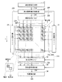
図1は、本発明の一実施の形態に係る表示装置の全体構成を表すものである。この表示装置は、表示部1と、表示信号生成部21と、表示信号保持制御部22と、表示信号ドライバ23と、発光用スキャナ24と、受光用スキャナ31と、受光信号レシーバ32と、受光信号保持部33と、位置検出部34とを備えている。この表示装置は、画像の表示と受光とを行うことの可能なものであり、画像データに基づく画像を表示部1に表示すると共に、この表示部1に接触または近接する物体(検出対象物体)の位置などを検出するものである。なお、本発明の一実施の形態に係る位置検出方法は、上記表示装置により具現化されるので、以下、合わせて説明する。
FIG. 1 shows the overall configuration of a display device according to an embodiment of the present invention. This display device includes a
表示部1は、複数の各画素11が表示部1の全面に渡ってマトリクス状に配置されたLCD(Liquid Crystal Display)からなり、後述するように線順次動作をしながら所定の図形や文字などの画像を表示するものである。
The
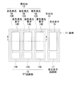
図2は、各画素11の構成の一例を平面図で表したものである。各画素11は、表示部1の表示面10(図3参照)に向けて可視光を発する発光セル12と、表示面10側から入射した可視光を受光する受光セル13とにより構成されている。発光セル12は、赤色発光する赤色発光セル12Rと、緑色発光する緑色発光セル12Gと、青色発光する青色発光セル12Bとを有している。赤色発光セル12Rは、赤色発光する部分である赤色発光素子14Rと、この赤色発光素子14Rを駆動するTFT(Thin Film Transistor)回路部15Rとを有している。同様に、緑色発光セル12Gは、緑色発光する部分である緑色発光素子14Gと、この緑色発光素子14Gを駆動するTFT回路部15Gとを有している。また、青色発光セル12Bは、青色発光する部分である青色発光素子14Bと、この青色発光素子14Bを駆動するTFT回路部15Bとを有している。一方、受光セル13は、可視光を受光する部分である受光素子16と、この受光素子16を駆動する受光センサ回路部17とを有している。受光素子16は、例えばフォトダイオードなどから構成されている。なお、これら赤色発光素子14R、緑色発光素子14Gおよび青色発光素子14BとTFT回路部15との接続関係、ならびにTFT回路部15と前述の表示信号ドライバ23、発光用スキャナ24、受光用スキャナ31および受光信号レシーバ32との接続関係の詳細については後述(図4)する。
FIG. 2 is a plan view showing an example of the configuration of each
図3は、図2におけるA−A部分の矢視断面図であり、表示部1の断面構成の一例を表したものである。この表示部1は、光源100上に、各発光素子(赤色発光素子14R、緑色発光素子14Gおよび青色発光素子14B)を構成する積層構造を有するパネル部110を備えたものである。このパネル部110は、いわゆる液晶表示パネルであり、具体的には光源100側から、偏光板101Aと、透明基板102Aと、回路部103と、絶縁層104と、透明画素電極105Aと、液晶層106と、透明電極105Bと、カラーフィルタ107と、選択透過フィルタ108と、ブラックマトリクス109と、透明基板102Bと、偏光板101Bとから構成されている。すなわち、これら各発光素子(赤色発光素子14R、緑色発光素子14Gおよび青色発光素子14B)は互いに対向する透明基板102A,102Bの間に液晶層106を設けた液晶表示パネル内に設けられている。
FIG. 3 is a cross-sectional view taken along the line AA in FIG. 2, and illustrates an example of a cross-sectional configuration of the
光源100は、可視光領域の光を上記した液晶素子へ向けて発するバックライトである。また、透明基板102A,102Bは、いずれも、例えばガラス材料により構成されている。ただし、これら102A,102Bをガラス材料の代わりに、透明なプラスチック材料などから構成してもよい。
The
回路部103は、図2に示したTFT回路部15や受光素子回路部17に対応する部分であり、各透明画素電極105Aと電気的に接続されている。また、透明画素電極105Aは各発光素子に配置されており、例えばITO(Indium Tin Oxide;酸化インジウムスズ)などの透明材料から構成される。一方、透明電極105Bは透明電極105Aと対向する共通電極であり、透明電極105Aと同様に例えばITOなどの透明材料から構成される。また、絶縁層104は、各回路部103の間に形成されている。このような構成により、これら透明電極105A,105B間に表示データに応じた電圧が印加され、光源100からのバックライト光Loが液晶層106を透過または遮断されるようになっている。
The circuit portion 103 is a portion corresponding to the
カラーフィルタ107は、各発光セル12(赤色発光セル12R、緑色発光セル12Gおよび青色発光セル12B)に対応する領域に配置されており、液晶層106を透過したバックライト光Loのうち、自己の発光色に対応する波長領域の光を選択的に透過するものである。ブラックマトリクス108は、各カラーフィルタ107の間に配置されており、光源100からのバックライト光Loを遮断して表示面10側に射出させないようにするものである。
The color filter 107 is disposed in a region corresponding to each light emitting cell 12 (the red
図4は、各画素11における回路構成の一例を表したものである。各画素11は、前述のように、赤色発光セル12R、緑色発光セル12Gおよび青色発光セル12Bからなる発光セル12と、受光セル13とを有している。このうち、発光セル12には、表示信号ドライバ23に接続された表示データ供給線DWと、発光用スキャナ24に接続された発光用ゲート線GWとが接続されている。具体的には、赤色発光セル12Rには表示データ供給線DWrと発光用ゲート線GWとが、緑色発光セル12Gには表示データ供給線DWgと発光用ゲート線GWとが、青色発光セル12Bには表示データ供給線DWbと発光用ゲート線GWとが、それぞれ接続されている。一方、受光セル13には、受光用スキャナ31に接続された受光用ゲート線GRおよび受光用リセット線RRと受光信号レシーバ32に接続されたデータ読み出し線DRとが接続されている。
FIG. 4 illustrates an example of a circuit configuration in each
ここで、赤色発光セル12Rは、前述の赤色発光素子14Rと、この赤色発光素子14Rを駆動する発光素子選択スイッチSW1Rを含むTFT回路部15Rとを有している。発光素子選択スイッチSW1Rの一端は表示データ供給線DWrに接続され、その他端は赤色発光素子14Rの一端(具体的には、前述の透明画素電極105A)に接続され、さらに、赤色発光素子14Rの他端(具体的には、前述の透明電極105B)は接地されている。同様に、緑色発光セル12Gは、前述の緑色発光素子14Gと、この緑色発光素子14Gを駆動する発光素子選択スイッチSW1Gを含むTFT回路部15Gとを有している。発光素子選択スイッチSW1Gの一端は表示データ供給線DWgに接続され、その他端は緑色発光素子14Gの一端に接続され、さらに、緑色発光素子14Gの他端は接地されている。また、青色発光セル12Bは、前述の青色発光素子14Bと、この青色発光素子14Bを駆動する発光素子選択スイッチSW1Bを含むTFT回路部15Bとを有している。発光素子選択スイッチSW1Bの一端は表示データ供給線DWbに接続され、その他端は青色発光素子14Bの一端に接続され、さらに、青色発光素子14Bの他端は接地されている。また、発光素子選択スイッチSW1R,SW1G,SW1Bはそれぞれ、発光用ゲート線GWによってそのオンオフ動作が制御されるようになっている。なお、発光素子選択スイッチSW1R,SW1G,SW1Bは、いずれも例えばTFTなどのスイッチ素子から構成される。
Here, the red
一方、受光セル13は、前述の受光素子16(図4に示した例ではフォトダイオード)と、前述の受光素子回路部17内に設けられた受光素子選択スイッチSW2,SW3、バッファアンプAMPおよび容量Cとを有している。受光素子16の一端が電源線VDDに接続され、その他端がバッファアンプAMPの入力端に接続されている。また、バッファアンプAMPの出力端が受光素子選択スイッチSW2の一端に接続され、受光素子選択スイッチSW2の他端がデータ読出線DRに接続されている。さらに、バッファアンプAMPの入力端が受光素子選択スイッチSW3の一端と、容量Cの一端とにそれぞれ接続され、受光素子選択スイッチSW3および容量Cのそれぞれの他端が接地されている。また、受光素子選択スイッチSW2は受光用ゲート線GRによってそのオンオフ動作が制御されるようになっており、受光素子選択スイッチSW3は受光用リセット線RRによってそのオンオフ動作が制御されるようになっている。なお、受光素子選択スイッチSW2,SW3は、いずれも例えばTFTなどのスイッチ素子から構成される。
On the other hand, the
次に、表示装置における表示部1以外の構成(表示信号生成部21、表示信号保持制御部22、表示信号ドライバ23、発光用スキャナ24、受光用スキャナ31、受光信号レシーバ32、受光信号保持部33および位置検出部34)について説明する。
Next, a configuration other than the
表示信号生成部21は、例えば図示しないCPU(Central Processing Unit)などから供給される画像データに基づいて、例えば1画面ごと(1フィールドの表示ごと)に表示部1に表示するための表示信号21Aを生成するものである。このようにして生成された表示信号21Aは、表示信号保持制御部22へ出力される。
The display
表示信号保持制御部22は、表示信号生成部21から出力された表示信号21Aを1画面ごと(1フィールドの表示ごと)に、例えばSRAM(Static Random Access Memory)などから構成されたフィールドメモリに格納して保持するものである。この表示信号保持制御部22はまた、各発光セル12を駆動する表示信号ドライバ23および発光用スキャナ24と、各受光セル13を駆動する受光用スキャナ31と、表示部1の光源100(後述)とが連動して動作するように制御する役割も果たしている。具体的には、発光用スキャナ24に対しては発光タイミング制御信号22Aを、受光用スキャナ31に対しては受光タイミング制御信号22Bを、表示信号ドライバ23に対してはフィールドメモリに保持されている1画面分の表示信号に基づく1水平ライン分の表示信号22Cを、表示部1の光源100に対しては、光源100を点灯または消灯させる光源制御信号22Dをそれぞれ出力するようになっている。より詳細には、表示信号保持制御部22は、例えば図5,図6に示したように、1フレームごとに画像(動画像または静止画像)の表示を行う際に、各フレーム期間Tを1/2に分割し、その前半期間T1または後半期間T2に、光源制御信号22Dとして光源100を点灯させる信号を出力して光源100全体を点灯させると共に、この点灯期間に、発光タイミング制御信号22A、受光タイミング制御信号22Bおよび表示信号22Cを出力し各発光セル12および各受光セル13を1水平ラインごとに同期して例えば矢印X方向(図1参照)へ駆動(線順次駆動)させ、各フレーム期間の前半および後半のうち上記点灯期間とは異なる期間に、光源制御信号22Dとして光源100を消灯させる信号を出力して光源100全体を消灯させると共に、この消灯期間に、受光タイミング制御信号22Bを出力し各受光セル13を1水平ラインごとに例えば矢印X方向へ駆動(線順次駆動)させるようになっている。なお、各受光セル13を、1フレーム周期で連続して駆動させる必要はなく、必要に応じて複数フレーム周期で断続的に駆動させるようにしてもよい。
The display signal holding
表示信号ドライバ23は、表示信号保持制御部22から出力される1水平ライン分の表示信号22Cに応じて、駆動対象の発光セル12へ表示データを供給するものである。具体的には、表示部1の各画素11に接続されたデータ供給線DWを介して、発光用スキャナ24により選択された画素11へ表示データに対応する電圧23Aを供給するようになっている。
The
発光用スキャナ24は、表示信号保持制御部22から出力される発光タイミング制御信号22Bに応じて、駆動対象の発光セル12を選択するものである。具体的には、表示部1の各画素11に接続された発光用ゲート線GWを介して駆動対象の可視光発光セル12へ発光用選択信号24Aを供給し、発光素子選択スイッチSW1R,SW1G,SW1Bを制御するようになっている。このようにして、この発光用選択信号24Aによってある画素11の発光素子選択スイッチSW1R,SW1G,SW1Bがオン状態となる電圧が発光素子選択スイッチSW1R,SW1G,SW1Bに印加されると、その画素では表示信号ドライバ23から供給された電圧23Aに対応した輝度の発光動作がなされるようになっている。このようにして、これら発光用スキャナ24および表示信号ドライバ23が連動して線順次動作することにより、任意の表示データに対応する画像が表示部1に表示されるようになっている。
The
受光用スキャナ31は、表示信号保持制御部22から出力される受光タイミング制御信号22Bに応じて、駆動対象の受光セル13を選択するものである。具体的には、表示部1の各画素11に接続された受光用ゲート線GRを介して駆動対象の受光セル13へ受光用選択信号31Aを供給し、受光素子選択スイッチSW2を制御すると共に、表示部1の各画素11に接続された受光用リセット線RRを介して駆動対象の受光セル13へリセット信号31Bを供給し、受光素子選択スイッチSW3を制御するようになっている。つまり、リセット信号31Bによってある画素11の受光素子選択スイッチSW3がオン状態となる電圧が受光素子選択スイッチSW3に印加されると、その画素11中の容量Cに蓄積された電荷がリセットされ、受光用選択信号31Aによってある画素11の受光素子選択スイッチSW2がオン状態となる電圧が受光素子選択スイッチSW2に印加されると、その画素11中の受光素子16での受光量に対応して容量Cに蓄積された電荷がバッファアンプAMPおよびデータ読み出し線DRを介して受光信号レシーバ32に受光信号1Aとして出力されるようになっている。このようにして、可視光が受光セル13によって受光される。
The
なお、この受光用スキャナ31は、受光信号レシーバ32および受光信号保持部33に対してそれぞれ受光ブロック制御信号31Cを出力し、これら受光動作に寄与する部分の動作を制御する役割も果たしている。
The
受光信号レシーバ32は、受光用スキャナ31から出力される受光ブロック制御信号31Cに応じて、各受光セル13から出力された1水平ライン分の受光信号1Aを取得するものである。このようにして取得された1水平ライン分の受光信号1Aは、受光信号保持部33へ出力される。
The light
受光信号保持部33は、受光用スキャナ31から出力される受光ブロック制御信号31Cに応じて、受光信号レシーバ32から出力される受光信号32Aを1画面ごと(1フィールドの表示ごと)の受光信号33A(受光画像)に再構成し、例えばSRAMなどから構成されるフィールドメモリ(図示せず)に格納して保持するものである。このようにしてフィールドメモリに格納された受光信号33Aは、位置検出部34へ出力される。なお、この受光信号保持部33はメモリ以外の記憶素子を有していてもよく、例えば受光信号33Aをアナログデータとして保持しておくようにしてもよい。
The light reception
位置検出部34は、受光信号保持部33から出力される受光信号33Aに対して所定の信号処理を行うことにより、表示面10に接触あるいは近接する物体(検出対称物)の位置などを特定するものである。なお、上記のように受光信号保持部33が受光信号33Aをアナログデータとして保持している場合には、この位置検出部34がアナログ/デジタル変換(A/D変換)を行ってから信号処理を実行するように構成することが可能である。
The
図7は、位置検出部34の各機能ブロックを表したものである。位置検出部34は、図7に示したように、反射検出処理部41と、影検出処理部42と、合成処理部43と、近接検出処理部44と、記憶部45とを有している。なお、本実施の形態の反射検出処理部41、影検出処理部42または合成処理部43が、本発明の「画像生成部」の一具体例に相当する。
FIG. 7 shows each functional block of the
反射検出処理部41は、表示信号保持制御部22から出力される光源制御信号22Dに応じて、受光信号保持部33から出力された受光信号33Aを、点灯期間(画像表示期間)に得られた点灯時受光画像(画像表示時受光画像)と、消灯期間(画像非表示期間)に得られた消灯時受光画像(画像非表示時受光画像)とに分類し、点灯時受光画像と消灯時受光画像との差分を取り(例えば点灯時受光画像のデータから消灯時受光画像のデータを減じ)、差分画像41Aを生成し合成処理部43へ出力するものである。
In response to the light
ここで、点灯時受光画像と消灯時受光画像とには、いずれも外光の成分が含まれていることから、点灯時受光画像と消灯時受光画像との差分を取ることにより、外光の成分を取り除くことができる。これにより、周囲の環境(明るさ)に依らない画像(差分画像41A)を得ることができる。
Here, since both the light receiving image when turned on and the light received image when turned off include an external light component, the difference between the light receiving image when turned on and the light received image when turned off can be obtained by calculating the difference between the light received image when turned on Ingredients can be removed. Thereby, an image (
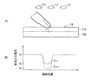
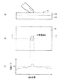
例えば、図8(A)に示したように、入射する外光L2が強い場合には、光源100を点灯させた状態での受光出力電圧Von1は、図8(B)に示したように、指で触れた個所以外では、外光L2の明るさに対応した電圧値Vaとなり、指で触れた個所では、そのときに触れた指の表面で、光源100からの光を反射させる反射率に対応した電圧値Vbに低下する。 これに対して、光源100を消灯させた状態での受光出力電圧Voff1は、指で触れた個所以外では、外光L2の明るさに対応した電圧値Vaとなる点は同じであるが、指で触れた個所では、外光L2が遮断された状態であり、非常にレベルの低い電圧値Vcとなる。
For example, as shown in FIG. 8A, when the incident external light L2 is strong, the light reception output voltage Von1 in the state where the
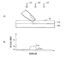
また、図9(A)に示したように、入射する外光L2が弱い(ほとんどない)状態では、光源100を点灯させた状態での受光出力電圧Von2は、図9(B)に示したように、指で触れた個所以外では、外光がないために非常にレベルの低い電圧値Vcの近傍となり、指で触れた個所では、そのときに触れた指の表面で、光源100からの光を反射させる反射率に対応した電圧値Vbに上昇する。これに対して、光源100を消灯させた状態での受光出力電圧Voff2は、指で触れた個所とそれ以外の個所のいずれでも、非常にレベルの低い電圧値Vcのままで変化がない。
Further, as shown in FIG. 9A, in the state where the incident external light L2 is weak (nearly present), the light reception output voltage Von2 when the
このように、図8(B),図9(B)を比較すると判るように、パネル部110の表示面10に接触していない個所では、外光L2がある場合と弱い(ほとんどない)場合とで、受光出力電圧が大きく異なっているが、光源100を点灯させた場合と消灯させた場合とで、受光出力電圧は変わらず、同じである。したがって、点灯時受光画像と消灯時受光画像との差分を取ることにより、外光L2の成分を取り除いた画像(差分画像41A)を得ることができる。また、指が接触している個所では、外光L2の大きさに関係なく、光源100の点灯時の電圧Vbと、光源100の消灯時の電圧Vcとが、ほぼ同じである。そのため、外光L2がある場合と弱い(ほとんどない)場合とで、差分画像41Aは、ほぼ同じとなり、外光L2の影響によって、得られる差分画像41Aのプロファイルが変動する虞はほとんどない。このように、本実施の形態では、周囲の環境(明るさ)に依らない画像(差分画像41A)を得ることができる。
Thus, as can be seen by comparing FIG. 8B and FIG. 9B, there is a case where the external light L2 is present and a case where the external light L2 is weak (almost not present) at a portion not in contact with the
影検出処理部42は、以下に示した手順を行うことにより影画像42Aを生成し、合成処理部43へ出力するものである。
The shadow
影検出処理部42は、まず、消灯期間に得られた消灯時受光画像(受光信号33A)の反転画像および移動平均画像を生成する。ここで、反転画像は、例えば、消灯時受光画像の明暗を反転させることにより得られる。また、移動平均画像は、例えば、消灯時受光画像における一の注目画素およびその周辺画素からなる画素領域の画素データに対して平均化処理を行い、その平均化処理により得られた画像データを、消灯時受光画像における次の注目画素およびその周辺画素からなる画素領域での平均化処理で用い、そして、注目画素を順次移動させ、平均化処理を消灯時受光画像全体について行うことにより得られる。
The shadow
なお、平均化処理を行う画素領域の大きさは、検出対称物の像として予想される大きさに基づいて設定する(たとえば、検出対称物の像と同程度の大きさに設定する)のが望ましい。このようにした場合には、平均化処理を行う画素領域の大きさと同程度の大きさの像が消灯時受光画像に含まれているときに、平均化処理によってその像の輪郭をぼやかすことができるので、例えば、検出対称物が指先である場合に、平均化処理を行う画素領域を指先の像の大きさと同程度の大きさとすることにより、指先の像と同程度の大きさの像の輪郭をぼやかし、後述する差分画像41Aの生成の際に、指先の像よりも大きな像(例えば拳の像)を消すことができ、その結果、拳を誤検出することを回避することができる。
Note that the size of the pixel area to be averaged is set based on the size expected as the image of the detected symmetrical object (for example, set to the same size as the image of the detected symmetrical object). desirable. In such a case, when an image having the same size as the size of the pixel area on which the averaging process is performed is included in the light-receiving image when extinguished, the outline of the image is blurred by the averaging process. Therefore, for example, when the detected object is the fingertip, the pixel area to be subjected to the averaging process is set to the same size as the image of the fingertip, so that the image has the same size as the image of the fingertip. When the
また、上述した方法を用いて平均化処理を行った場合には、消灯時受光画像の外縁領域が注目画素から外れるが、その外縁領域の画素データについては、何らかの補間処理を行うことが好ましい。例えば、消灯時受光画像のうち平均化処理の行われた領域の最外縁の画素における画素データを、その画素の外側の画素における画素データとしてそのままコピーするようにしてもよい。 Further, when the averaging process is performed using the above-described method, the outer edge area of the light-receiving image when the light is extinguished deviates from the target pixel, but it is preferable to perform some interpolation processing on the pixel data of the outer edge area. For example, the pixel data in the pixel at the outermost edge of the area subjected to the averaging process in the light-receiving image at the time of extinction may be copied as it is as the pixel data in the pixel outside the pixel.
次に、影検出処理部42は、移動平均画像から、後の処理で利用する所定の閾値を算出する。具体的には、移動平均画像における最も明るい(最も画素データの大きい)画素の画素データと、平均化処理を行う前の消灯時受光画像における最も暗い(最も画素データの小さい)画素の画素データとに基づいて(たとえば、これらの画素データの平均を取って)閾値を求める。なお、最も明るい(最も画素データの大きい)画素の画素データについては、表示面10の四隅には同時に検出対称物が配置されることは通常ないものとして、これら四隅の画素の画素データの平均値を割り当てるようにしてもよい。
Next, the shadow
次に、影検出処理部42は、移動平均画像の反転画像を生成する。ここで、反転画像は、例えば、移動平均画像の明暗を反転させることにより得られる。続いて、影検出処理部42は、消灯時受光画像の反転画像と、移動平均画像の反転画像との差分を取り(例えば、消灯時受光画像の反転画像のデータから移動平均画像の反転画像のデータを減じ)、差分画像を生成したのち、この差分画像の各画素データから、あらかじめ求めておいた閾値を減じて、影画像42Aを生成する。
Next, the shadow
なお、差分画像の各画素データから閾値を減じることにより、差分画像に含まれる、検出対称物以外の物体の像に対応する画素データの値を小さくし、検出対称物以外の物体を誤検出することを回避することができる。 In addition, by subtracting a threshold value from each pixel data of the difference image, the value of the pixel data corresponding to the image of the object other than the detection symmetry object included in the difference image is reduced, and the object other than the detection symmetry object is erroneously detected. You can avoid that.
合成処理部43は、反射検出処理部41から出力された差分画像41Aと、影検出処理部42から出力された影画像42Aとを合成することにより、合成画像43Aを生成し、近接検出処理部44へ出力するものである。
The
差分画像41Aと影画像42Aとの合成は、差分画像41Aの各画素データに所定の係数α(0<α<1)をかけたものと、影画像42Aの各画素データに所定の係数(1−α)をかけたものとを加算することにより行うことが好ましい。ただし、他の方法を用いて合成画像43Aを生成するようにしてもよい。
The
なお、必要に応じて、合成処理部43の出力(合成画像43A)の代わりに、反射検出処理部41の出力(差分画像41A)または影検出処理部42の出力(影画像42A)を近接検出処理部44に入力するようにしてもよい。例えば、本実施の形態のようにパネル110に半透過型の液晶素子を用いている場合において、表示装置を屋外で利用するときのように、光源100が常時オフ状態になるときや、黒画像がパネル110に表示されているときなどには、影検出処理部42の出力(影画像42A)を近接検出処理部44に入力することが好ましい。
If necessary, the output of the reflection detection processing unit 41 (
近接検出処理部44は、判定処理部51と、対象物特定処理部52とを有している。なお、本実施の形態の判定処理部51が、本発明の「画像判定部」の一具体例に相当し、本実施の形態の対象物特定処理部52が、本発明の「位置導出部」の一具体例に相当する。
The proximity detection processing unit 44 includes a determination processing unit 51 and an object specifying
判定処理部51は、受光信号保持部33の出力(点灯時受光画像および消灯時受光画像)に基づいて生成された画像に、検出対象物の像が含まれているか否か判定し、その判定結果に応じて記憶部45内の初期データ45Aや検出データ45Bを更新するものである。なお、受光信号保持部33の出力に基づいて生成された画像(判定用画像)は、合成処理部43の出力を近接検出処理部44に入力する場合には合成画像43Aに相当し、反射検出処理部41の出力を近接検出処理部44に入力する場合には差分画像41Aに相当し、影検出処理部42の出力を近接検出処理部44に入力する場合には影画像42Aに相当する。
The determination processing unit 51 determines whether or not the image generated based on the output of the light reception signal holding unit 33 (light reception image when turned on and light reception image when turned off) includes an image of the detection target. The
判定用画像に検出対象物の像が含まれているか否かは、例えば図10(A)〜(C)に示したように、判定用画像の各画素データ内に所定の閾値THを超える値を有する画素領域Rが存在するか否かを検出し、画素領域Rが検出された場合には、画素領域Rの大きさと、検出対称物の像として予想される大きさとを互いに対比することにより行われる。例えば、判定処理部51は、対象領域Rの縦横スケールが検出対称物の像として予想される大きさ(M×N(M,Nは画素数))以上となっている場合には、判定用画像に検出対称物の像が含まれていると判定し、対象領域Rの縦横スケールが対象領域Rの縦横スケールが検出対称物の像として予想される大きさ(M×N(M,Nは画素数))を下回っている場合には、判定用画像に検出対称物の像は含まれていないと判定する。このように、判定処理部51は、簡易なルールに基づいて、判定用画像に検出対象物の像が含まれているか否かを判定する。 Whether or not the image of the detection object is included in the image for determination is a value exceeding a predetermined threshold TH in each pixel data of the image for determination as shown in FIGS. 10 (A) to (C), for example. Is detected, and when the pixel region R is detected, the size of the pixel region R and the size expected as an image of the detected symmetrical object are compared with each other. Done. For example, the determination processing unit 51 determines whether or not the vertical and horizontal scales of the target region R are larger than an expected size (M × N (M and N are the number of pixels)) as an image of the detected symmetrical object. It is determined that the image of the detection symmetric object is included in the image, and the vertical and horizontal scales of the target region R are expected to be the size that the vertical and horizontal scales of the target region R are expected as the detection symmetric image (M × N (M and N are If the number of pixels is less than the number of pixels)), it is determined that the image for detection does not include the image of the detection symmetry object. As described above, the determination processing unit 51 determines whether or not the image for detection includes the image of the detection target based on a simple rule.
判定処理部51は、判定用画像に検出対称物の像が含まれていないと判定した場合には、判定用画像を初期データ45Aとして記憶部45に記憶させ、判定用画像に検出対称物の像が含まれていると判定した場合には、判定用画像を検出データ45Bとして記憶部45に記憶させる。このようにして判定用画像を記憶部45に記憶させた後に、判定処理終了信号51Aが対象物特定処理部52へ出力される。
When the determination processing unit 51 determines that the image for detection does not include the image of the detection symmetry object, the determination processing unit 51 stores the determination image in the storage unit 45 as the
なお、記憶部45にデフォルトデータが初期データ45Aとしてあらかじめ格納されている場合や、過去のフレーム期間Tにおける受光信号保持部33の出力(点灯時受光画像および消灯時受光画像)に基づいて生成された判定用画像などが判定処理部51による処理により初期データ45Aとして既に格納されている場合には、判定用画像を最新の初期データ45Aとして記憶部45に上書きするようにしてもよいし、初期データ45Aとして既に格納されている画像と、判定用画像とを合成することにより得られる合成画像を最新の初期データ45Aとして記憶部45に上書きするようにしてもよい。また、判定用画像を検出データ45Bとして記憶部45に記憶させる際に、判定用画像をそのまま、または判定用画像に対して何らかの処理を施したものを検出データ45Bとして記憶部45に記憶させてもよい。
Note that the default data is stored in the storage unit 45 in advance as the
初期データ45Aとして既に格納されている画像と、新たに初期データ45Aとして格納する判定用画像との合成は、初期データ45Aとして既に格納されている画像の各画素データに所定の係数β(0<β<1)をかけたものと、新たに初期データ45Aとして格納する判定用画像の各画素データに所定の係数(1−β)をかけたものとを加算することにより行うことが好ましい。ただし、他の方法を用いて合成画像を生成するようにしてもよい。
The synthesis of the image already stored as the
対象物特定処理部52は、判定処理部51から出力された判定処理終了信号51Aが入力されると、記憶部45に検出データ45Bとして記憶されている画像から、記憶部45に初期データ45Aとして記憶されている画像を減じて、解析用画像を生成し、この解析用画像を用いて(例えば解析用画像を2値化して)、検出対象物の位置情報44Aを導出し、例えばCPU(図示せず)などへ出力するものである。
When the determination processing
なお、記憶部45に検出データ45Bとして記憶されている画像から、記憶部45に初期データ45Aとして記憶されている画像を減じることにより、記憶部45に検出データ45Bとして記憶されている画像に含まれる、検出対称物の像に対応する画素データの値だけを抽出することができ、位置情報44Aを容易に導出することができる。
In addition, by subtracting the image stored as the
次に、本実施の形態の表示装置の動作の一例について詳細に説明する。 Next, an example of the operation of the display device of this embodiment will be described in detail.
この表示装置では、図示しないCPUなどから供給される表示データに基づいて、表示信号ドライバ23および発光用スキャナ24から表示用の駆動信号(電圧23A、発光用選択信号24A)が生成され、この駆動信号により、表示部1において線順次表示駆動がなされ、画像が表示されると共に、受光用スキャナ31から受光用の駆動信号(受光用選択信号31A)が生成され、この駆動信号により、表示部1において線順次受光駆動がなされ、画像が撮像される。また、このとき光源100は表示信号保持制御部22によって駆動され、表示部1と同期した点灯・消灯動作が行われる。
In this display device, based on display data supplied from a CPU (not shown) or the like, a display drive signal (
具体的には、例えば図5に示したように、1フレームごとに画像の表示を行う際に、各フレーム期間Tを1/2に分割し、その前半期間T1に、光源制御信号22Dとして光源100を点灯させる信号を出力して光源100全体を点灯させると共に、この点灯期間に、表示用の駆動信号(電圧23A、発光用選択信号24A)および受光用の駆動信号(受光用選択信号31A)が出力され、各発光セル12および各受光セル13が1水平ラインごとに同期して例えば矢印X方向(図1参照)へ駆動(線順次駆動)されて、そのフレーム期間の画像が表示されると共に、前半期間T1の受光信号33Aが点灯時受光画像(画像表示時受光画像)として得られる。さらに、各フレーム期間の後半期間T2に、光源制御信号22Dとして光源100を消灯させる信号を出力して光源100全体を消灯させると共に、この消灯期間に、受光用の駆動信号(受光用選択信号31A)が出力され、各受光セル13が1水平ラインごとに例えば矢印X方向へ駆動(線順次駆動)されて、後半期間T2の受光信号33Aが消灯時受光画像(画像非表示時受光画像)として得られる。なお、各受光セル13が複数フレーム周期で断続的に駆動されている場合には、各受光セル13が駆動されたフレーム期間だけ受光信号33Aが消灯時受光画像として得られる。
Specifically, for example, as shown in FIG. 5, when displaying an image for each frame, each frame period T is divided into ½, and the light
そして、位置検出部34において、受光信号保持部33から出力される受光信号33Aに基づいて信号処理が行われ、表示面10に接触あるいは近接する物体(検出対称物)の位置などが特定される。
Then, the
(画像生成ステップ)
具体的には、まず、反射検出処理部41において、表示信号保持制御部22から出力される光源制御信号22Dに応じて、受光信号保持部33から出力された受光信号33Aが点灯時受光画像と消灯時受光画像とに分類され、点灯時受光画像と消灯時受光画像との差分から差分画像41Aが生成される。また、影検出処理部42において、消灯時受光画像から反転画像および移動平均画像が生成されると共に、移動平均画像から反転画像および閾値が生成される。さらに、影検出処理部42において、消灯時受光画像の反転画像と、移動平均画像の反転画像との差分から差分画像が生成され、その差分画像の各画素データから、あらかじめ求めておいた閾値を減じることにより影画像42Aが生成される。続いて、合成処理部43において、差分画像41Aと影画像42Aとが所定のルールで合成されることにより合成画像43Aが生成される。
(Image generation step)
Specifically, first, in the reflection
(画像判定ステップ)
次に、判定処理部51において、受光信号保持部33の出力(点灯時受光画像および消灯時受光画像)に基づいて生成された判定用画像(合成画像43A、差分画像41Aまたは影画像42A)に検出対象物の像が含まれているか否かが上述した簡易なルールに基づいて判定される。さらに、判定処理部51において、上記画像に検出対称物の像が含まれていないと判定された場合には、その画像が初期データ45Aとして記憶部45に記憶され、上記画像に検出対称物の像が含まれていると判定された場合には、その画像が検出データ45Bとして記憶部45に記憶される。
(Image judgment step)
Next, in the determination processing unit 51, the determination image (the
このとき、記憶部45にデフォルトデータが初期データ45Aとしてあらかじめ格納されている場合や、過去のフレーム期間Tにおける受光信号保持部33の出力(点灯時受光画像および消灯時受光画像)に基づいて生成された過去の判定用画像などが判定処理部51による処理により初期データ45Aとして既に格納されている場合には、判定用画像を最新の初期データ45Aとして記憶部45に上書きするか、または、初期データ45Aとして既に格納されている画像と、判定用画像とを所定のルールで合成することにより得られる合成画像を最新の初期データ45Aとして記憶部45に上書きする。
At this time, the default data is stored in advance in the storage unit 45 as the
(位置導出ステップ)
次に、対象物特定処理部52において、記憶部45に検出データ45Bとして記憶されている画像から、記憶部45に初期データ45Aとして記憶されている画像を減じることにより、解析用画像が生成され、この解析用画像を用いて、検出対象物の位置情報44Aが導出され、例えばCPU(図示せず)などへ出力される。このようにして、本実施の形態では、表示面10に接触あるいは近接する物体(検出対称物)の位置などが特定される。
(Position derivation step)
Next, in the object
このように、本実施の形態では、1フレーム期間において、光源100の点灯(画像の表示)と光源100の消灯(画像の非表示)が順次行われている時に、点灯期間(画像表示期間)に点灯時受光画像(画像表示時受光画像)を撮像すると共に、消灯期間(画像非表示期間)に消灯時受光画像(画像非表示時受光画像)を撮像し、これら点灯時受光画像および消灯時受光画像に対して所定の信号処理を施したものを検出対象物の位置の導出に用いるようにしたので、物体の位置などを検出する時の外光の影響をなくすることができるの。これにより、周囲の環境(明るさ)が変化した場合であっても、周囲の環境に拘わらず、表示装置の表示面に接触あるいは近接する物体の位置などを容易に検出することができる。
As described above, in this embodiment, when the
また、この判定用画像に対して所定の処理を施したものを初期データ45Aとして用いるようにしたので、物体の位置などを検出する時に表示装置内で発生しているノイズの影響をなくすることができる。これにより、表示装置内で発生するノイズが表示装置を使用する環境の変化や、経時変化などによって変化した場合であっても、表示装置内で発生するノイズ成分を効果的に除去することができるので、表示装置の表示面に接触あるいは近接する物体の位置などを精度よく検出することができる。また、表示装置内で発生するノイズを除去するために、工場出荷時などにあらかじめ用意しておいたデータを初期データ45Aとして記憶部45に記憶させておく必要がないので、工場出荷時の工数を低減することができる。
In addition, since an image obtained by performing a predetermined process on the determination image is used as the
また、本実施の形態では、判定用画像に検出対象物の像が含まれているか否かを、上記したように簡易なルールに基づいて行うようにしたので、初期データ45Aとして記憶部45に記憶させるデータを生成するために要する処理時間や負荷を十分に小さくすることができ、位置検出の応答速度の低下を最低限に抑えることができる。また、初期データ45Aの生成は表示装置側で自動的に行われるので、表示装置のユーザに何らかの操作を要求することがなく、上記特許文献1の技術と比べて、ユーザの負担を軽減することができる。
In the present embodiment, whether or not the image of the detection target is included in the determination image is determined based on the simple rule as described above, and therefore, the
また、本実施の形態において、記憶部45にデフォルトデータが初期データ45Aとしてあらかじめ格納されている場合や、過去のフレーム期間Tにおける受光信号保持部33の出力(点灯時受光画像および消灯時受光画像)に基づいて生成された過去の判定用画像などが判定処理部51による処理により初期データ45Aとして既に格納されている場合に、初期データ45Aとして既に格納されている画像と、判定用画像とを所定のルールで合成することにより得られる合成画像を最新の初期データ45Aとして記憶部45に上書きするようにしたときには、簡易なルールに基づいて判定用画像に検出対象物の像が含まれているか否かを判定した際に、判定用画像に検出対象物の像が含まれているにも拘わらず、判定用画像に検出対象物の像が含まれていないと誤検出してしまったときでも、その誤検出の影響が長引くのを防止することができ、さらに、誤検出によって、位置検出の精度が低下するのを最低限に抑えることができる。
Further, in the present embodiment, when the default data is stored in advance as the
また、本実施の形態では、検出対称物の位置などを検出するうえで、例えばタッチパネルなどの部品を別途設ける必要がないので、表示装置の構成を簡素化することができる。 Further, in this embodiment, it is not necessary to separately provide a component such as a touch panel when detecting the position of the detection symmetry object, and the configuration of the display device can be simplified.
また、本実施の形態において、各受光セル13を複数フレーム周期で断続的に駆動するようにした場合には、検出対称物の位置などを検出するのに要する消費電力を低く抑えることができる。
Further, in the present embodiment, when each light receiving
以上、実施の形態およびその変形例を挙げて本発明を説明したが、本発明は実施の形態等に限定されるものではなく、種々の変形が可能である。 Although the present invention has been described with reference to the embodiment and its modifications, the present invention is not limited to the embodiment and the like, and various modifications can be made.
例えば、上記実施の形態では、各画素11は、赤色発光セル12R、緑色発光セル12Gおよび青色発光セル12Bからなる発光セル12を有していたが、他の色を発するセルをさらに備えていてもよく、また、これらの発光セルのうち少なくとも1つのセルを備えていてもよい。
For example, in the above embodiment, each
また、上記実施の形態では、表示部1は、光源100上に液晶表示パネル(パネル部110)を備えている場合について説明していたが、表示部1が、互いに対向する透明基板の間に有機層を設けた有機ELパネルのように、画素を構成する表示素子自体が発光する自発光型パネルを備えていてもよい。ただし、その場合には、表示素子をオンオフ動作させることにより、画像表示・非表示と、点灯・消灯とを同時に行うことになるので、表示部1の背面に光源100を設け、表示素子のオンオフ動作と共に、光源100のオンオフ動作を行う必要はない。
Moreover, in the said embodiment, although the
1…表示部、100…光源、101A,101B…偏光板、102A,102B…透明基板、103…回路部、104…絶縁層、105A…透明画素電極、105B…透明電極、106…液晶層、107…カラーフィルタ、108…選択透過フィルタ、109…ブラックマトリクス、10…表示面、11…画素、12…発光セル、12R…赤色発光セル、12G…緑色発光セル、12B…青色発光セル、13…受光セル、14R…赤色発光素子、14G…緑色発光素子、14B…青色発光素子、15,15R,15G,15B…TFT回路部、16…受光素子、17…受光素子回路部、21…表示信号生成部、22…表示信号保持制御部、23…表示信号ドライバ、24…発光用スキャナ、31…受光用スキャナ、32…受光信号レシーバ、33…受光信保持部、34…位置検出部、41…反射検出処理部、42…影検出処理部、43…合成処理部、44…近接検出処理部、45…記憶部、45A…初期データ、45B…検出データ、51…判定処理部51、52…対象物特定処理部。
DESCRIPTION OF
Claims (13)
初期データおよび検出データを記憶する記憶部と、
前記検出光が前記表示面から出力されている第1の期間に前記複数の受光セルから得られた第1の受光画像の各画素データと、前記検出光が前記表示面から出力されていない第2の期間に前記複数の受光セルから得られた第2の受光画像の各画素データとの差分をとることにより判定用画像を生成する画像生成部と、
前記判定用画像の各画素データ内に所定の閾値を超える値を有する画素領域が存在するか否かを検出し、前記画素領域が検出された場合には、前記画素領域の大きさと、検出対象物の像として予想される大きさとを互いに対比することにより、前記判定用画像に検出対象物の像が含まれているか否かを判定し、前記判定用画像に検出対象物の像が含まれていないと判定した場合には、前記判定用画像に対応するデータを前記初期データとして前記記憶部に記憶させ、前記判定用画像に検出対象物の像が含まれていると判定した場合には、前記判定用画像に対応するデータを前記検出データとして前記記憶部に記憶させる画像判定部と、
前記記憶部に前記検出データとして記憶された画像と、前記記憶部に前記初期データとして記憶された画像との差分から、検出対象物の位置を導出する位置導出部と
を備えた表示装置。 A panel unit having a plurality of light emitting cells for displaying an image on the display surface and emitting detection light and a plurality of light receiving cells for receiving the detection light incident from the display surface side;
A storage unit for storing initial data and detection data;
Each pixel data of the first light receiving image obtained from the plurality of light receiving cells in the first period in which the detection light is output from the display surface, and the detection light is not output from the display surface. An image generation unit that generates a determination image by taking a difference with each pixel data of a second light reception image obtained from the plurality of light reception cells in a period of two;
It is detected whether or not a pixel area having a value exceeding a predetermined threshold exists in each pixel data of the image for determination, and when the pixel area is detected, the size of the pixel area and the detection target It is determined whether or not the image for detection includes the image of the detection target object by comparing with the expected size as the image of the object, and the image for detection includes the image of the detection target object. If it is determined that the image for detection is not stored, data corresponding to the image for determination is stored in the storage unit as the initial data, and if it is determined that the image for detection includes the image of the detection object An image determination unit that stores data corresponding to the determination image in the storage unit as the detection data;
A display device comprising: a position deriving unit for deriving a position of a detection object from a difference between an image stored as the detection data in the storage unit and an image stored as the initial data in the storage unit.
初期データおよび検出データを記憶する記憶部と、A storage unit for storing initial data and detection data;
(1)前記検出光が前記表示面から出力されていない期間に前記複数の受光セルから得られた受光画像の明暗を反転させることにより第1反転画像を生成し、(2)前記受光画像における一の注目画素およびその周辺画素からなる画素領域の画素データに対して平均化処理を行い、その平均化処理により得られた画像データに対して、前記受光画像における次の注目画素およびその周辺画素からなる画素領域での平均化処理を用い、注目画素を順次移動させ、平均化処理を前記受光画像全体について行うことにより移動平均画像を生成し、(3)前記移動平均画像の明暗を反転させることにより第2反転画像を生成し、(4)前記移動平均画像から所定の閾値を生成し、(5)前記第1反転画像と前記第2反転画像との差分から差分画像を生成し、その差分画像の各画素データから前記閾値を減じることにより判定用画像を生成する画像生成部と、(1) A first inverted image is generated by inverting the brightness of the received light image obtained from the plurality of light receiving cells during a period when the detection light is not output from the display surface, and (2) in the received light image Averaging processing is performed on pixel data in a pixel region including one target pixel and its peripheral pixels, and the next target pixel and its peripheral pixels in the received light image are obtained with respect to image data obtained by the averaging processing. The pixel of interest is averaged and the pixel of interest is sequentially moved, and the averaging process is performed on the entire received light image to generate a moving average image. (3) The brightness of the moving average image is inverted. Thus, a second inverted image is generated, (4) a predetermined threshold value is generated from the moving average image, and (5) a difference image is generated from the difference between the first inverted image and the second inverted image. And an image generating unit that generates a determination image by subtracting the threshold from each pixel data of the differential image,
前記判定用画像の各画素データ内に所定の閾値を超える値を有する画素領域が存在するか否かを検出し、前記画素領域が検出された場合には、前記画素領域の大きさと、検出対象物の像として予想される大きさとを互いに対比することにより、前記判定用画像に検出対象物の像が含まれているか否かを判定し、前記判定用画像に検出対象物の像が含まれていないと判定した場合には、前記判定用画像に対応するデータを前記初期データとして前記記憶部に記憶させ、前記判定用画像に検出対象物の像が含まれていると判定した場合には、前記判定用画像に対応するデータを前記検出データとして前記記憶部に記憶させる画像判定部と、It is detected whether or not a pixel area having a value exceeding a predetermined threshold exists in each pixel data of the image for determination, and when the pixel area is detected, the size of the pixel area and the detection target It is determined whether or not the image for detection includes the image of the detection target object by comparing with the expected size as the image of the object, and the image for detection includes the image of the detection target object. If it is determined that the image for detection is not stored, data corresponding to the image for determination is stored in the storage unit as the initial data, and if it is determined that the image for detection includes the image of the detection object An image determination unit that stores data corresponding to the determination image in the storage unit as the detection data;
前記記憶部に前記検出データとして記憶された画像と、前記記憶部に前記初期データとして記憶された画像との差分から、検出対象物の位置を導出する位置導出部とA position deriving unit for deriving the position of the detection object from the difference between the image stored as the detection data in the storage unit and the image stored as the initial data in the storage unit;
を備えた表示装置。A display device comprising:
初期データおよび検出データを記憶する記憶部と、A storage unit for storing initial data and detection data;
前記検出光が前記表示面から出力されている第1の期間に前記複数の受光セルから得られた第1の受光画像と、前記検出光が前記表示面から出力されていない第2の期間に前記複数の受光セルから得られた第2の受光画像とに基づいて判定用画像を生成する画像生成部と、A first light receiving image obtained from the plurality of light receiving cells during a first period in which the detection light is output from the display surface, and a second period in which the detection light is not output from the display surface. An image generating unit that generates a determination image based on the second received light image obtained from the plurality of light receiving cells;
前記判定用画像の各画素データ内に所定の閾値を超える値を有する画素領域が存在するか否かを検出し、前記画素領域が検出された場合には、前記画素領域の大きさと、検出対象物の像として予想される大きさとを互いに対比することにより、前記判定用画像に検出対象物の像が含まれているか否かを判定し、前記判定用画像に検出対象物の像が含まれていないと判定した場合には、前記判定用画像に対応するデータを前記初期データとして前記記憶部に記憶させ、前記判定用画像に検出対象物の像が含まれていると判定した場合には、前記判定用画像に対応するデータを前記検出データとして前記記憶部に記憶させる画像判定部と、It is detected whether or not a pixel area having a value exceeding a predetermined threshold exists in each pixel data of the image for determination, and when the pixel area is detected, the size of the pixel area and the detection target It is determined whether or not the image for detection includes the image of the detection target object by comparing with the expected size as the image of the object, and the image for detection includes the image of the detection target object. If it is determined that the image for detection is not stored, data corresponding to the image for determination is stored in the storage unit as the initial data, and if it is determined that the image for detection includes the image of the detection object An image determination unit that stores data corresponding to the determination image in the storage unit as the detection data;
前記記憶部に前記検出データとして記憶された画像と、前記記憶部に前記初期データとして記憶された画像との差分から、検出対象物の位置を導出する位置導出部とA position deriving unit for deriving the position of the detection object from the difference between the image stored as the detection data in the storage unit and the image stored as the initial data in the storage unit;
を備え、With
前記画像生成部は、The image generation unit
前記第1の受光画像の各画素データと前記第2の受光画像の各画素データとの差分から第1差分画像を生成する差分画像生成部と、A difference image generation unit that generates a first difference image from a difference between each pixel data of the first light reception image and each pixel data of the second light reception image;
(1)前記第2の受光画像の明暗を反転させることにより第1反転画像を生成し、(2)前記第2の受光画像における一の注目画素およびその周辺画素からなる画素領域の画素データに対して平均化処理を行い、その平均化処理により得られた画像データに対して、前記第2の受光画像における次の注目画素およびその周辺画素からなる画素領域での平均化処理を行い、注目画素を順次移動させ、平均化処理を前記第2の受光画像全体について行うことにより移動平均画像を生成し、(3)前記移動平均画像の明暗を反転させることにより第2反転画像を生成し、(4)前記移動平均画像から所定の閾値を生成し、(5)前記第1反転画像と前記第2反転画像との差分から第2差分画像を生成し、その第2差分画像の各画素データから前記閾値を減じることにより影画像を生成する影画像生成部と、(1) A first inverted image is generated by inverting the brightness of the second light receiving image, and (2) pixel data of a pixel region including one target pixel and its peripheral pixels in the second light receiving image. An averaging process is performed on the image data obtained by the averaging process, and an averaging process is performed on a pixel area including the next pixel of interest in the second received light image and its surrounding pixels. Sequentially moving the pixels, generating a moving average image by performing an averaging process on the entire second light-receiving image, and (3) generating a second inverted image by inverting the contrast of the moving average image, (4) A predetermined threshold value is generated from the moving average image, (5) a second difference image is generated from a difference between the first inverted image and the second inverted image, and each pixel data of the second difference image To the threshold A shadow image generation unit for generating a shadow image by subtracting,
前記第1差分画像と前記影画像とを所定のルールで合成することにより前記判定用画像を生成する合成画像生成部とA composite image generation unit configured to generate the determination image by combining the first difference image and the shadow image according to a predetermined rule;
を有するHave
表示装置。Display device.
請求項1ないし請求項3のいずれか一項に記載の表示装置。 When the image determination unit determines that the image for detection does not include an image of a detection symmetry object, and the predetermined image is already stored as the initial data in the storage unit, the image determination unit Overwriting the storage unit as the initial data with the image as it is or after performing a predetermined process on the determination image, or an image already stored in the storage unit as the initial data; The display device according to any one of claims 1 to 3 , wherein a composite image obtained by combining the determination image with a predetermined rule is overwritten in the storage unit as the initial data.
請求項1または請求項3に記載の表示装置。 The first period is a display period in which an image is displayed on the display surface, the second period is a non-display period in which no image is displayed on the display surface, and the detection light displays an image. the display device according to claim 1 or claim 3 is a display light for.
請求項2に記載の表示装置。The display device according to claim 2.
請求項1ないし請求項3のいずれか一項に記載の表示装置。 Wherein together with a plurality of light emitting cells visible light for displaying an image on the display surface, the display according to any one of claims 1 to 3 for emitting invisible light from the display surface as said detection light apparatus.
前記非可視光は赤外光である
請求項7に記載の表示装置。 The panel unit is a liquid crystal display panel in which a liquid crystal layer is provided between transparent substrates facing each other,
The display device according to claim 7 , wherein the invisible light is infrared light.
請求項1ないし請求項3のいずれか一項に記載の表示装置。 The panel unit, a display device according to any one of claims 1 to 3 is a liquid crystal display panel provided with a liquid crystal layer between the transparent substrates facing each other.
請求項1ないし請求項3のいずれか一項に記載の表示装置。 The display device according to any one of claims 1 to 3 , wherein the panel unit is an organic light emitting panel in which an organic layer is provided between transparent substrates facing each other.
前記検出光が前記表示面から出力されている第1の期間に前記複数の受光セルから得られた第1の受光画像の各画素データと、前記検出光が前記表示面から出力されていない第2の期間に前記複数の受光セルから得られた第2の受光画像の各画素データとの差分をとることにより判定用画像を生成する画像生成ステップと、
前記判定用画像の各画素データ内に所定の閾値を超える値を有する画素領域が存在するか否かを検出し、前記画素領域が検出された場合には、前記画素領域の大きさと、検出対象物の像として予想される大きさとを互いに対比することにより、前記判定用画像に検出対象物の像が含まれているか否かを判定し、前記判定用画像に検出対象物の像が含まれていないと判定した場合には、前記判定用画像に対応するデータを前記初期データとして前記記憶部に記憶させ、前記判定用画像に検出対象物の像が含まれていると判定した場合には、前記判定用画像に対応するデータを前記検出データとして前記記憶部に記憶させる画像判定ステップと、
前記記憶部に前記検出データとして記憶された画像と、前記記憶部に前記初期データとして記憶された画像との差分から、検出対象物の位置を導出する位置導出ステップと
を含む位置検出方法。 A panel unit having a plurality of light emitting cells for displaying an image on the display surface and emitting detection light and a plurality of light receiving cells for receiving the detection light incident from the display surface side, and a memory for storing initial data and detection data A method for detecting the position of a detection object in a display device comprising:
Each pixel data of the first light receiving image obtained from the plurality of light receiving cells in the first period in which the detection light is output from the display surface, and the detection light is not output from the display surface. An image generation step of generating a determination image by taking a difference with each pixel data of the second light receiving image obtained from the plurality of light receiving cells in the period of 2;
It is detected whether or not a pixel area having a value exceeding a predetermined threshold exists in each pixel data of the image for determination, and when the pixel area is detected, the size of the pixel area and the detection target It is determined whether or not the image for detection includes the image of the detection target object by comparing with the expected size as the image of the object, and the image for detection includes the image of the detection target object. If it is determined that the image for detection is not stored, data corresponding to the image for determination is stored in the storage unit as the initial data, and if it is determined that the image for detection includes the image of the detection object An image determination step of storing data corresponding to the determination image in the storage unit as the detection data;
A position detection method comprising: a position deriving step of deriving a position of a detection target object from a difference between an image stored as the detection data in the storage unit and an image stored as the initial data in the storage unit.
(1)前記検出光が前記表示面から出力されていない期間に前記複数の受光セルから得られた受光画像の明暗を反転させることにより第1反転画像を生成し、(2)前記受光画像における一の注目画素およびその周辺画素からなる画素領域の画素データに対して平均化処理を行い、その平均化処理により得られた画像データに対して、前記受光画像における次の注目画素およびその周辺画素からなる画素領域での平均化処理を用い、注目画素を順次移動させ、平均化処理を前記受光画像全体について行うことにより移動平均画像を生成し、(3)前記移動平均画像の明暗を反転させることにより第2反転画像を生成し、(4)前記移動平均画像から所定の閾値を生成し、(5)前記第1反転画像と前記第2反転画像との差分から差分画像を生成し、その差分画像の各画素データから前記閾値を減じることにより判定用画像を生成する画像生成ステップと、(1) A first inverted image is generated by inverting the brightness of the received light image obtained from the plurality of light receiving cells during a period when the detection light is not output from the display surface, and (2) in the received light image Averaging processing is performed on pixel data in a pixel region including one target pixel and its peripheral pixels, and the next target pixel and its peripheral pixels in the received light image are obtained with respect to image data obtained by the averaging processing. The pixel of interest is averaged and the pixel of interest is sequentially moved, and the averaging process is performed on the entire received light image to generate a moving average image. (3) The brightness of the moving average image is inverted. Thus, a second inverted image is generated, (4) a predetermined threshold value is generated from the moving average image, and (5) a difference image is generated from the difference between the first inverted image and the second inverted image. And an image generation step of generating a determination image by subtracting the threshold from each pixel data of the differential image,
前記判定用画像の各画素データ内に所定の閾値を超える値を有する画素領域が存在するか否かを検出し、前記画素領域が検出された場合には、前記画素領域の大きさと、検出対象物の像として予想される大きさとを互いに対比することにより、前記判定用画像に検出対象物の像が含まれているか否かを判定し、前記判定用画像に検出対象物の像が含まれていないと判定した場合には、前記判定用画像に対応するデータを前記初期データとして前記記憶部に記憶させ、前記判定用画像に検出対象物の像が含まれていると判定した場合には、前記判定用画像に対応するデータを前記検出データとして前記記憶部に記憶させる画像判定ステップと、It is detected whether or not a pixel area having a value exceeding a predetermined threshold exists in each pixel data of the image for determination, and when the pixel area is detected, the size of the pixel area and the detection target It is determined whether or not the image for detection includes the image of the detection target object by comparing with the expected size as the image of the object, and the image for detection includes the image of the detection target object. If it is determined that the image for detection is not stored, data corresponding to the image for determination is stored in the storage unit as the initial data, and if it is determined that the image for detection includes the image of the detection object An image determination step of storing data corresponding to the determination image in the storage unit as the detection data;
前記記憶部に前記検出データとして記憶された画像と、前記記憶部に前記初期データとして記憶された画像との差分から、検出対象物の位置を導出する位置導出ステップとA position deriving step for deriving the position of the detection object from the difference between the image stored as the detection data in the storage unit and the image stored as the initial data in the storage unit;
を含む位置検出方法。A position detection method including:
前記検出光が前記表示面から出力されている第1の期間に前記複数の受光セルから得られた第1の受光画像と、前記検出光が前記表示面から出力されていない第2の期間に前記複数の受光セルから得られた第2の受光画像とに基づいて判定用画像を生成する画像生成ステップと、A first light receiving image obtained from the plurality of light receiving cells during a first period in which the detection light is output from the display surface, and a second period in which the detection light is not output from the display surface. An image generating step for generating a determination image based on the second light receiving images obtained from the plurality of light receiving cells;
前記判定用画像の各画素データ内に所定の閾値を超える値を有する画素領域が存在するか否かを検出し、前記画素領域が検出された場合には、前記画素領域の大きさと、検出対象物の像として予想される大きさとを互いに対比することにより、前記判定用画像に検出対象物の像が含まれているか否かを判定し、前記判定用画像に検出対象物の像が含まれていないと判定した場合には、前記判定用画像に対応するデータを前記初期データとして前記記憶部に記憶させ、前記判定用画像に検出対象物の像が含まれていると判定した場合には、前記判定用画像に対応するデータを前記検出データとして前記記憶部に記憶させる画像判定ステップと、It is detected whether or not a pixel area having a value exceeding a predetermined threshold exists in each pixel data of the image for determination, and when the pixel area is detected, the size of the pixel area and the detection target It is determined whether or not the image for detection includes the image of the detection target object by comparing with the expected size as the image of the object, and the image for detection includes the image of the detection target object. If it is determined that the image for detection is not stored, data corresponding to the image for determination is stored in the storage unit as the initial data, and if it is determined that the image for detection includes the image of the detection object An image determination step of storing data corresponding to the determination image in the storage unit as the detection data;
前記記憶部に前記検出データとして記憶された画像と、前記記憶部に前記初期データとして記憶された画像との差分から、検出対象物の位置を導出する位置導出ステップとA position deriving step for deriving the position of the detection object from the difference between the image stored as the detection data in the storage unit and the image stored as the initial data in the storage unit;
を含み、Including
前記画像生成ステップにおいて、In the image generation step,
(1)前記第1の受光画像の各画素データと前記第2の受光画像の各画素データとの差分から第1差分画像を生成し、(1) generating a first difference image from a difference between each pixel data of the first received light image and each pixel data of the second received light image;
(2)前記第2の受光画像の明暗を反転させることにより第1反転画像を生成し、(2) generating a first inverted image by inverting the brightness of the second received light image;
(3)前記第2の受光画像における一の注目画素およびその周辺画素からなる画素領域の画素データに対して平均化処理を行い、その平均化処理により得られた画像データに対して、前記第2の受光画像における次の注目画素およびその周辺画素からなる画素領域での平均化処理を行い、注目画素を順次移動させ、平均化処理を前記第2の受光画像全体について行うことにより移動平均画像を生成し、(3) An averaging process is performed on pixel data of a pixel region including one target pixel and its peripheral pixels in the second received light image, and the image data obtained by the averaging process is subjected to the first The moving average image is obtained by performing the averaging process in the pixel region including the next target pixel and its peripheral pixels in the two received light images, sequentially moving the target pixel, and performing the averaging process on the entire second received light image. Produces
(4)前記移動平均画像の明暗を反転させることにより第2反転画像を生成し、(4) generating a second inverted image by inverting the contrast of the moving average image;
(5)前記移動平均画像から所定の閾値を生成し、(5) generating a predetermined threshold value from the moving average image;
(6)前記第1反転画像と前記第2反転画像との差分から第2差分画像を生成し、その第2差分画像の各画素データから前記閾値を減じることにより影画像を生成し、(6) generating a second difference image from the difference between the first inverted image and the second inverted image, and generating a shadow image by subtracting the threshold from each pixel data of the second difference image;
(7)前記第1差分画像と前記影画像とを所定のルールで合成することにより前記判定用画像を生成する(7) The determination image is generated by combining the first difference image and the shadow image according to a predetermined rule.
位置検出方法。Position detection method.
Priority Applications (6)
| Application Number | Priority Date | Filing Date | Title |
|---|---|---|---|
| JP2008059501A JP4623110B2 (en) | 2008-03-10 | 2008-03-10 | Display device and position detection method |
| TW098105003A TWI402727B (en) | 2008-03-10 | 2009-02-17 | Display apparatus and position detecting method |
| US12/390,925 US8154535B2 (en) | 2008-03-10 | 2009-02-23 | Display apparatus and position detecting method |
| KR1020090019708A KR20090097123A (en) | 2008-03-10 | 2009-03-09 | Display apparatus and position detecting method |
| CN200910126663A CN101533323A (en) | 2008-03-10 | 2009-03-10 | Display apparatus and position detecting method |
| US13/441,391 US8466903B2 (en) | 2008-03-10 | 2012-04-06 | Display apparatus and position detecting method |
Applications Claiming Priority (1)
| Application Number | Priority Date | Filing Date | Title |
|---|---|---|---|
| JP2008059501A JP4623110B2 (en) | 2008-03-10 | 2008-03-10 | Display device and position detection method |
Publications (3)
| Publication Number | Publication Date |
|---|---|
| JP2009217461A JP2009217461A (en) | 2009-09-24 |
| JP2009217461A5 JP2009217461A5 (en) | 2010-04-22 |
| JP4623110B2 true JP4623110B2 (en) | 2011-02-02 |
Family
ID=41053112
Family Applications (1)
| Application Number | Title | Priority Date | Filing Date |
|---|---|---|---|
| JP2008059501A Expired - Fee Related JP4623110B2 (en) | 2008-03-10 | 2008-03-10 | Display device and position detection method |
Country Status (5)
| Country | Link |
|---|---|
| US (2) | US8154535B2 (en) |
| JP (1) | JP4623110B2 (en) |
| KR (1) | KR20090097123A (en) |
| CN (1) | CN101533323A (en) |
| TW (1) | TWI402727B (en) |
Families Citing this family (38)
| Publication number | Priority date | Publication date | Assignee | Title |
|---|---|---|---|---|
| JP4844602B2 (en) * | 2008-08-20 | 2011-12-28 | ソニー株式会社 | Display device, display control device, display control method, and program |
| JP2012177953A (en) * | 2009-06-30 | 2012-09-13 | Sharp Corp | Optical sensor and display device |
| KR20110009973A (en) * | 2009-07-23 | 2011-01-31 | 삼성전자주식회사 | Display system and method of cotrolling the display system |
| WO2011024347A1 (en) * | 2009-08-25 | 2011-03-03 | シャープ株式会社 | Coordinate sensor and display device |
| KR101042955B1 (en) * | 2009-09-02 | 2011-06-20 | 삼성모바일디스플레이주식회사 | Organic light emitting display apparatus with touch screen |
| KR101319346B1 (en) * | 2009-09-15 | 2013-10-16 | 엘지디스플레이 주식회사 | Embedded Photo-Sensing type Touch Panel in Liquid Crystal Display Device and Method for Driving the Same |
| KR101264727B1 (en) * | 2009-09-24 | 2013-05-15 | 엘지디스플레이 주식회사 | Liquid Crystal Display Device with an Embedded Touch Panel therein |
| CN102511025B (en) * | 2009-09-30 | 2015-02-04 | 夏普株式会社 | Display device |
| EP2485126A4 (en) * | 2009-09-30 | 2014-07-30 | Sharp Kk | Display device |
| US20120268439A1 (en) * | 2009-09-30 | 2012-10-25 | Sharp Kabushiki Kaisha | Display Device |
| RU2012117771A (en) * | 2009-09-30 | 2013-11-10 | Шарп Кабусики Кайся | DISPLAY DEVICE |
| JP5424475B2 (en) * | 2009-10-13 | 2014-02-26 | 株式会社ジャパンディスプレイ | Information input device, information input method, information input / output device, information input program, and electronic device |
| KR101843561B1 (en) * | 2009-10-26 | 2018-03-30 | 가부시키가이샤 한도오따이 에네루기 켄큐쇼 | Display device and semiconductor device |
| TWI424339B (en) * | 2009-11-04 | 2014-01-21 | Coretronic Corp | Optical touch apparatus and driving mothod |
| WO2011065555A1 (en) * | 2009-11-30 | 2011-06-03 | シャープ株式会社 | Display device |
| US10216336B2 (en) | 2010-01-20 | 2019-02-26 | Nexys | Control device and electronic device comprising same |
| FR2955403B1 (en) * | 2010-01-20 | 2016-07-29 | Neocreativ | CONTROL DEVICE AND ELECTRONIC DEVICE COMPRISING SAME |
| WO2011104924A1 (en) * | 2010-02-26 | 2011-09-01 | シャープ株式会社 | Display device with light sensor |
| WO2011145677A1 (en) * | 2010-05-20 | 2011-11-24 | シャープ株式会社 | Display device equipped with touch sensor |
| JP5823740B2 (en) * | 2010-06-16 | 2015-11-25 | 株式会社半導体エネルギー研究所 | I / O device |
| WO2012014819A1 (en) * | 2010-07-26 | 2012-02-02 | シャープ株式会社 | Display device |
| US20130120331A1 (en) * | 2010-07-27 | 2013-05-16 | Sharp Kabushiki Kaisha | Display device |
| KR101710657B1 (en) | 2010-08-05 | 2017-02-28 | 삼성디스플레이 주식회사 | Display device and driving method thereof |
| US20130241891A1 (en) * | 2010-11-04 | 2013-09-19 | Sharp Kabushiki Kaisha | Photosensor builtin display apparatus |
| US10126803B1 (en) | 2011-04-04 | 2018-11-13 | Google Llc | Conditional power management activities |
| TWI441060B (en) | 2011-04-14 | 2014-06-11 | Pixart Imaging Inc | Image processing method for optical touch system |
| KR20120124224A (en) * | 2011-05-03 | 2012-11-13 | 삼성디스플레이 주식회사 | Organic light emitting display apparatus |
| CN102866809A (en) * | 2011-07-04 | 2013-01-09 | 光宝新加坡有限公司 | Click detection method of optical navigation module |
| US20130076693A1 (en) * | 2011-09-23 | 2013-03-28 | Lite-On Singapore Pte. Ltd. | Tapping detection method of optical navigation module |
| EP2645215B1 (en) * | 2012-03-28 | 2019-08-14 | Siemens Aktiengesellschaft | Display device with read back display |
| US9601059B2 (en) * | 2012-05-15 | 2017-03-21 | Google Inc. | Dynamic backlight control selector |
| CN103019467A (en) * | 2012-11-27 | 2013-04-03 | 鸿富锦精密工业(深圳)有限公司 | Optical touch screen |
| CN103049139A (en) * | 2012-12-07 | 2013-04-17 | 鸿富锦精密工业(深圳)有限公司 | Photosensitive input device and input panel |
| CN103049140A (en) * | 2012-12-07 | 2013-04-17 | 鸿富锦精密工业(深圳)有限公司 | Photosensitive type input-and-output device and photosensitive type input-and-output panel |
| JP6553406B2 (en) * | 2014-05-29 | 2019-07-31 | 株式会社半導体エネルギー研究所 | Program and information processing apparatus |
| JP6704802B2 (en) * | 2016-06-10 | 2020-06-03 | 株式会社ジャパンディスプレイ | Input detection device and electronic device |
| CN109992395B (en) * | 2017-12-29 | 2021-11-16 | Oppo广东移动通信有限公司 | Application freezing method and device, terminal and computer readable storage medium |
| WO2022198393A1 (en) * | 2021-03-22 | 2022-09-29 | 京东方科技集团股份有限公司 | Display device |
Citations (5)
| Publication number | Priority date | Publication date | Assignee | Title |
|---|---|---|---|---|
| JP2004199714A (en) * | 1997-08-07 | 2004-07-15 | Fujitsu Ltd | Optical scanning touch panel |
| JP2005215860A (en) * | 2004-01-28 | 2005-08-11 | Canon Inc | Light shielding type coordinate input device |
| JP2006244446A (en) * | 2005-02-03 | 2006-09-14 | Toshiba Matsushita Display Technology Co Ltd | Display device |
| JP2006276223A (en) * | 2005-03-28 | 2006-10-12 | Sony Corp | Display apparatus and method |
| JP2007025796A (en) * | 2005-07-12 | 2007-02-01 | Sony Corp | Display device and display method |
Family Cites Families (4)
| Publication number | Priority date | Publication date | Assignee | Title |
|---|---|---|---|---|
| KR101085447B1 (en) * | 2004-12-31 | 2011-11-21 | 삼성전자주식회사 | Touch position detecting device and method of touch position detecting the same and touch screen display device having the same |
| JP4645822B2 (en) * | 2005-04-19 | 2011-03-09 | ソニー株式会社 | Image display device and object detection method |
| JP2007281003A (en) * | 2006-04-03 | 2007-10-25 | Canon Inc | Measuring method and device, and exposure device |
| JP5014971B2 (en) * | 2007-12-19 | 2012-08-29 | ソニーモバイルディスプレイ株式会社 | Display device |
-
2008
- 2008-03-10 JP JP2008059501A patent/JP4623110B2/en not_active Expired - Fee Related
-
2009
- 2009-02-17 TW TW098105003A patent/TWI402727B/en not_active IP Right Cessation
- 2009-02-23 US US12/390,925 patent/US8154535B2/en not_active Expired - Fee Related
- 2009-03-09 KR KR1020090019708A patent/KR20090097123A/en not_active Application Discontinuation
- 2009-03-10 CN CN200910126663A patent/CN101533323A/en active Pending
-
2012
- 2012-04-06 US US13/441,391 patent/US8466903B2/en not_active Expired - Fee Related
Patent Citations (5)
| Publication number | Priority date | Publication date | Assignee | Title |
|---|---|---|---|---|
| JP2004199714A (en) * | 1997-08-07 | 2004-07-15 | Fujitsu Ltd | Optical scanning touch panel |
| JP2005215860A (en) * | 2004-01-28 | 2005-08-11 | Canon Inc | Light shielding type coordinate input device |
| JP2006244446A (en) * | 2005-02-03 | 2006-09-14 | Toshiba Matsushita Display Technology Co Ltd | Display device |
| JP2006276223A (en) * | 2005-03-28 | 2006-10-12 | Sony Corp | Display apparatus and method |
| JP2007025796A (en) * | 2005-07-12 | 2007-02-01 | Sony Corp | Display device and display method |
Also Published As
| Publication number | Publication date |
|---|---|
| US8154535B2 (en) | 2012-04-10 |
| JP2009217461A (en) | 2009-09-24 |
| US20090225058A1 (en) | 2009-09-10 |
| KR20090097123A (en) | 2009-09-15 |
| US20120194480A1 (en) | 2012-08-02 |
| US8466903B2 (en) | 2013-06-18 |
| CN101533323A (en) | 2009-09-16 |
| TWI402727B (en) | 2013-07-21 |
| TW200945144A (en) | 2009-11-01 |
Similar Documents
| Publication | Publication Date | Title |
|---|---|---|
| JP4623110B2 (en) | Display device and position detection method | |
| JP4626658B2 (en) | Display device, imaging device, and position detection device | |
| US8665223B2 (en) | Display device and method providing display contact information based on an amount of received light | |
| US7671848B2 (en) | Display device and display method | |
| TWI288384B (en) | Display device and information terminal device | |
| JP5347035B2 (en) | Display device with optical sensor | |
| US8610670B2 (en) | Imaging and display apparatus, information input apparatus, object detection medium, and object detection method | |
| JP5111327B2 (en) | Display imaging apparatus and electronic apparatus | |
| JP4915367B2 (en) | Display imaging apparatus and object detection method | |
| KR20070063419A (en) | Display | |
| JP4697552B2 (en) | Image display device and driving method of image display device | |
| WO2010047256A1 (en) | Imaging device, display image device, and electronic device | |
| US9201532B2 (en) | Information input device, information input program, and electronic instrument | |
| JP2009128835A (en) | Liquid crystal display device | |
| JP5247139B2 (en) | Display device and method, program, and electronic apparatus | |
| CN101281445A (en) | Display apparatus | |
| JP4270247B2 (en) | Display imaging apparatus, object detection program, and object detection method | |
| JP4788232B2 (en) | Display device and display method | |
| JP2009199204A (en) | Electro-optical device, control method thereof, and electronic equipment | |
| JP4788755B2 (en) | Display imaging apparatus, object detection program, and object detection method | |
| JP2010092192A (en) | Display imaging apparatus and electronic device |
Legal Events
| Date | Code | Title | Description |
|---|---|---|---|
| A521 | Request for written amendment filed |
Free format text: JAPANESE INTERMEDIATE CODE: A523 Effective date: 20100308 |
|
| A621 | Written request for application examination |
Free format text: JAPANESE INTERMEDIATE CODE: A621 Effective date: 20100308 |
|
| A977 | Report on retrieval |
Free format text: JAPANESE INTERMEDIATE CODE: A971007 Effective date: 20100708 |
|
| A131 | Notification of reasons for refusal |
Free format text: JAPANESE INTERMEDIATE CODE: A131 Effective date: 20100805 |
|
| A521 | Request for written amendment filed |
Free format text: JAPANESE INTERMEDIATE CODE: A523 Effective date: 20100913 |
|
| TRDD | Decision of grant or rejection written | ||
| A01 | Written decision to grant a patent or to grant a registration (utility model) |
Free format text: JAPANESE INTERMEDIATE CODE: A01 Effective date: 20101005 |
|
| A01 | Written decision to grant a patent or to grant a registration (utility model) |
Free format text: JAPANESE INTERMEDIATE CODE: A01 |
|
| A61 | First payment of annual fees (during grant procedure) |
Free format text: JAPANESE INTERMEDIATE CODE: A61 Effective date: 20101018 |
|
| R151 | Written notification of patent or utility model registration |
Ref document number: 4623110 Country of ref document: JP Free format text: JAPANESE INTERMEDIATE CODE: R151 |
|
| FPAY | Renewal fee payment (event date is renewal date of database) |
Free format text: PAYMENT UNTIL: 20131112 Year of fee payment: 3 |
|
| FPAY | Renewal fee payment (event date is renewal date of database) |
Free format text: PAYMENT UNTIL: 20131112 Year of fee payment: 3 |
|
| S111 | Request for change of ownership or part of ownership |
Free format text: JAPANESE INTERMEDIATE CODE: R313113 |
|
| FPAY | Renewal fee payment (event date is renewal date of database) |
Free format text: PAYMENT UNTIL: 20131112 Year of fee payment: 3 |
|
| R350 | Written notification of registration of transfer |
Free format text: JAPANESE INTERMEDIATE CODE: R350 |
|
| R250 | Receipt of annual fees |
Free format text: JAPANESE INTERMEDIATE CODE: R250 |
|
| R250 | Receipt of annual fees |
Free format text: JAPANESE INTERMEDIATE CODE: R250 |
|
| R250 | Receipt of annual fees |
Free format text: JAPANESE INTERMEDIATE CODE: R250 |
|
| R250 | Receipt of annual fees |
Free format text: JAPANESE INTERMEDIATE CODE: R250 |
|
| R250 | Receipt of annual fees |
Free format text: JAPANESE INTERMEDIATE CODE: R250 |
|
| R250 | Receipt of annual fees |
Free format text: JAPANESE INTERMEDIATE CODE: R250 |
|
| LAPS | Cancellation because of no payment of annual fees |