JP4620825B2 - Fan sealing device - Google Patents
Fan sealing device Download PDFInfo
- Publication number
- JP4620825B2 JP4620825B2 JP2000059405A JP2000059405A JP4620825B2 JP 4620825 B2 JP4620825 B2 JP 4620825B2 JP 2000059405 A JP2000059405 A JP 2000059405A JP 2000059405 A JP2000059405 A JP 2000059405A JP 4620825 B2 JP4620825 B2 JP 4620825B2
- Authority
- JP
- Japan
- Prior art keywords
- ring
- throttle
- piece
- shroud
- reverse
- Prior art date
- Legal status (The legal status is an assumption and is not a legal conclusion. Google has not performed a legal analysis and makes no representation as to the accuracy of the status listed.)
- Expired - Fee Related
Links
Images


Description
【0001】
【発明の属する技術分野】
本発明は自動車用ラジエータ等に使用される軸流型または斜流型のファンのシール装置に関し、詳しくは翼先端部を相互に連結するリングとその半径方向外側に配置されるシュラウドの筒状部間に逆流防止用のラビリンスシールを設けた前記ファンのシール装置に関するものである。
【0002】
【従来の技術】
従来から、自動車用ラジエータ等に使用されている軸流型または斜流型のファンは、エンジンやモータ等の駆動源により回転するボス部と、ボス部に放射状に連結された複数の翼を備え、翼の回転により軸方向に送風するようになっている。
自動車用ラジエータ等のファンには、その翼部外周にシュラウドの筒状部が被嵌され、翼部先端付近の逆流を可能な限り防止している。
【0003】
一方、特殊な形状のために翼の強度を補強するため、その先端縁間をリングで相互に連結する方法が採用される。このような翼については、リングの遮蔽効果により逆流がある程度減少するのでシュラウドの筒状部は一般に省略される。
しかし上記いずれの逆流防止方法も近年の厳しい性能要求からは満足できるものとは言い難い。そこでさらに効果的な逆流防止の方法として、シュラウドの筒状部とリングの両者を組み合わせて使用し、それらの間にラビリンスシール効果を発揮する部分を形成したものが知られている。(例えば特公昭40ー4953号公報、実開昭53ー128906号公報等)
【0004】
一般にラビリンスシールは回転機器の軸受部のシールを目的として使用され、回転側である軸と固定側である軸受部の間に絞り片と空間部を交互に設けて構成される。そしてシール部の流れは絞り片によって形成される絞り口を通過する際に等エントロピー膨張し、そこで減速し膨張室(空間部)内で等圧のもとで静温度に回復し、さらに次の絞り口に流入するという工程を繰り返すことによりシール効果を奏するようになっている。
前記公報に記載された方法は回転側をリング、固定側をシュラウドの筒状部とし、シュラウドの筒状部の内周面に設けた凹部に翼の外周部を連結するリングを受け入れ、その凹部にシール部を形成している。
【0005】
【発明が解決しようとする課題】
しかし、このようにシュラウドの筒状部の凹部にリングを挿入した構造では、シュラウドの筒状部の軸方向からファンを挿入して組み立てることが難かしい。それを解決するには例えばシュラウドの筒状部を分割型とし、各分割部分をファンの外側から組み付ける必要があり、それだけ構造が複雑となりコストアップになるという別の問題が発生する。そこで本発明はこのような問題を解決した新しいファンのシール装置を提供することを課題とするものである。
【0006】
【課題を解決するための手段】
すなわち請求項1に記載の発明は、ボス部2aに複数の翼3を放射状に設けた軸流型または斜流型のファン1のシール装置において、
各翼3の先端縁間を互に連結するリング4と、リング4の半径方向外側に間隙を有して配置されたシュラウドの筒状部5を備え、
リング4の外周に複数の環状の絞り片Sが突設され、シュラウドの筒状部5の内周が平坦に形成されて、そのリング4とシュラウドの筒状部5との間に逆流を防止するラビリンスシール部8が形成され、
前記絞り片Sの外周直径が、シュラウドの筒状部5の内周直径より小さく形成されて、リング4がシュラウドの筒状部5内に軸方向から挿脱自在に構成され、
そのラビリンスシール部8がリング4の軸方向両端部または該両端部と中間部に設けた絞り片Sにより直通型に形成され、
リング4の軸方向の少なくとも一端部が、端に向かってその直径が次第に大きくなる円環状のベルマウスMに形成されると共に、そのベルマウスMの半径方向の高さが他の絞り片Sのそれと同一高さに形成され、
そのベルマウスMはリング4の端部の空気流の乱れや渦の発生を防止すると共に、絞り片Sを兼ねていることを特徴とするファンのシール装置である。
【0007】
請求項2に記載の本発明は、ボス部2aに複数の翼3を放射状に設けた軸流型または斜流型のファン1のシール装置において、
各翼3の先端縁間を互に連結するリング4と、リング4の半径方向外側に間隙を有して配置されたシュラウドの筒状部5を備え、
リング4の外周に複数の環状の絞り片Sが突設されるとともに、シュラウドの筒状部5の内周に複数の環状の逆絞り片Rが突設されて、そのリング4とシュラウドの筒状部5との間に逆流を防止するラビリンスシール部8が形成され、
前記絞り片Sの外周直径が、シュラウドの逆絞り片Rの内周直径より小さく形成されて、
リング4がシュラウドの筒状部5内に軸方向から挿脱自在に構成され、
前記ラビリンスシール部8が、リング4の軸方向両端部または該両端部と中間部に設けた絞り片Sと、夫々の絞り片Sの間に位置し、シュラウドの筒状部5の内面に突設された逆絞り片Rとで形成された食い違い型に形成され、
リング4の軸方向の少なくとも一端部が、端に向かってその直径が次第に大きくなる円環状のベルマウスMに形成されると共に、そのベルマウスMの半径方向の高さが他の絞り片Sのそれと同一高さに形成され、
そのベルマウスMはリング4の端部の空気流の乱れや渦の発生を防止すると共に、絞り片Sを兼ねていることを特徴とするファンのシール装置である。
【0008】
請求項3に記載の発明は、請求項2において、
逆流方向の上流側に位置する絞り片S1から逆絞り片Rを経て下流側の絞り片S2を通過する逆流fが、逆絞り片Rで分流されその一部が下流側の絞り片S2で反転するように、リング4の外周面4aからの絞り片S1,S2の高さH1,H2と逆絞り片Rの高さH3、および前記絞り片S1とS2間の軸方向の距離Lを選定するファンのシール装置である。
請求項4に記載の発明は、請求項3において、
上流側の絞り片S1と逆絞り片Rとの間隔Cが、0≦C≦0.75(mm)の範囲(ただしH1,H2,Lの間は、0.2≦H1/L≦1.5、および0.8H1≦H2の関係にある)にあるファンのシール装置である。
【0009】
【発明の実施の形態】
次に、本発明の実施の形態を図面により説明する。
図1(a)は本発明のシール装置を自動車用ラジエータ等の熱交換器の冷却ファンに適用した例で、その縦断面図、(b)は(a)のA−A矢視図である。軸流型または斜流型のファン1は図示しないエンジンのクランク軸により回転される駆動軸2と、その駆動軸2が連結されるボス部2aと、そのボス部2aに放射状に取り付けられた複数の翼3を有している。各翼3の先端縁間は相互にリング4により連結され、リング4の半径方向外側には所定の間隙をもってシュラウドの筒状部5が配置される。
リング4には半径方向に延長する環状の仕切り片等の絞り片Sが所定間隔で複数設けられる。なおこの例はリング4の両端部に空気流の乱れや渦の発生を防止するための円環状のベルマウスMを設けたものであり、それらベルマウスMが両端部の絞り片Sを兼用している。
【0010】
一方、シュラウドの筒状部5は、浅い漏斗状のシュラウド本体6を介してラジエータ等の熱交換器7に連結され、この例ではシュラウドの筒状部5とシュラウド本体6とは別体に成形され、締結具等により両者が固定されている。なお、シュラウド本体6とシュラウドの筒状部5を一体に形成してもよい。
シュラウドの筒状部5の内周面はリング4の絞り片Sの外周縁と僅かな間隙を有して対向している。そしてシュラウドの筒状部5の内周面と複数の絞り片Sによって、いわゆる直通型のラビリンスシール部8が形成される。このようなラビリンスシール部8においては、シュラウドの筒状部5の内周面と絞り片Sの先端の間隙により絞り口が形成され、翼3の下流側からの逆流がその絞り口を通過する際に等エントロピー膨張し、減速した逆流は隣接する絞り片Sの中間にある空間部(膨張室)において等圧で静温度に回復するという、作用を繰り返すことによりラビリンスシール効果を有効に発揮させている。
【0011】
このように各絞り片Sの先端とリング4の外周面の間には極わずかな間隙を有しているが、リング4とシュラウドの筒状部5との間には半径方向に重複する部分が存在しない。即ち、各絞り片Sの外周直径がシュラウドの筒状部5の内周直径よりも小さい。そのためシュラウドの筒状部5内にファン1を軸方向から挿入することにより、容易に図1の状態に組み立てることができる。
【0012】
図2は図1の変形例を示す部分断面図である。この例ではリング4の一方の端部にのみベルマウスMが形成され、ベルマウスMのない他端および中間部に仕切り片からなる絞り片Sが設けられる点が図1の例と異なり、そのほかは同様に構成されている。仕切り片からなる絞り片Sは一体的にリング4に成形してもよいが、接着や溶着などによってリング4に取り付けてもよい。
なおベルマウスMは一方の端部における絞り片Sを兼用し、シュラウドの筒状部5の内周面とリング4の複数の絞り片Sによって、直通型のラビリンスシール部8が形成され、その作用は図1と同様である。
【0013】
図3は本発明のシール装置の他の例を示す部分断面図である。この例も図2と同様にリング4の一方の端部にのみベルマウスMが形成され、ベルマウスMのない他端および中間部には仕切り片からなる絞り片Sが設けられるが、さらにシュラウドの筒状部5の内周面に複数の逆絞り片Rが設けられる。このように絞り片Sと逆絞り片Rを所定間隔で交互に設けることにより、いわゆる食い違い型のラビリンスシール部8が形成される。そして絞り片Sと逆絞り片Rの先端は半径方向に重複しないように構成される。即ち、絞り片Sの外直径は逆絞り片Rの内直径よりも小さい。
【0014】
図4は上記のように構成された食い違い型のラビリンスシール部8の作用を説明するために図3の一部を拡大して示した図である。シュラウドの筒状部5の内周面に形成された逆絞り片Rを挟んで逆流方向の上流側に位置する絞り片をS1、下流側に位置する絞り片をS2とすると、逆絞り片Rを経て下流側の絞り片S2を通過する逆流fが逆絞り片Rで分流され、その一部が下流側の絞り片S2で反転するように構成すると有効にラビリンスシール効果を発揮させることが、実験により確かめられた。
このような逆流fの反転作用を生じさせるためには、リング4の外周面4aからの絞り片S1,S2の高さと逆絞り片Rの高さ、絞り片S1とS2間の距離の関係を実験等によって所定の範囲に選定すればよい。
【0015】
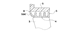
図5は上記各部の関係をより具体的に説明する図で、リング4の外周面4aからの絞り片S1,S2の先端までの高さを夫々H1,H2、逆絞り片Rの高さをH3、前記絞り片S1とS2間の軸方向の距離をL、絞り片S1の先端と逆絞り片Rの先端との距離をCとしたとき、実験によれば、Cの値が0≦C≦0.75(mm)の範囲(ただしH1,H2,Lの間は、0.2≦H1/L≦1.5および0.8H1≦H2の関係にあるものとする)にあるとき、絞り片と逆絞り片の先端が半径方向に重複しないように構成された食い違い型のラビリンスシール部8の場合であっても、ラビリンスシール効果を有効に奏することが判明した。
参考までに、図6に上流側の絞り片S1と逆絞り片Rとの間隔Cと逆流量の実験結果を示す。
これまで説明したシール装置は、軸流型のファンに適用した例であるが、本発明は斜流型のファンについても同様に適用できることは言うまでもない。
【0016】
【発明の効果】
以上のように本発明のファンのシール装置によれば、リングとシュラウドの筒状部の間に有効なラビリンスシール部が形成されると共に、リングで連結された各翼をシュラウドの筒状部内に軸方向から容易に挿入することができる。
さらに、ラビリンスシール部をリングの軸方向両端部または該両端部と中間部に設けた絞り片Sにより直通型に形成すると共に、リング4の軸方向の少なくとも一端部にベルマウスMに形成し、そのベルマウスMの半径方向の高さを他の絞り片Sのそれ高さと同一高さに形成し、そのベルマウスMがリング4の端部の空気流の乱れや渦の発生を防止すると共に、絞り片Sを兼ねさせたので、効率よく、より簡単な構造で本発明の上記効果を発揮させることができる。
【0017】
ラビリンスシール部をリング側の軸方向両端部または該両端部と中間部に設けた絞り片Sとシュラウドの筒状部側に設けた逆絞り片Rにより形成される食い違い型とし、且つ絞り片Sと逆絞り片Rの先端が半径方向に重複しないように構成する場合には、それによってより高いシール効果を有しながら本発明の上記効果を発揮させることができる。
さらに上記食い違い型のラビリンスシール部を有するファンのシール装置において、逆流方向の上流側に位置する絞り片S1から逆絞り片Rを経て下流側の絞り片S2を通過する逆流を、逆絞り片Rで分流させその一部が下流側の絞り片S2で反転するように構成する場合には、それによってより高いシール効果を有しながら本発明の上記効果を安定して発揮させることができる。
【図面の簡単な説明】
【図1】本発明のシール装置を自動車用熱交換器の冷却ファンに適用した例で、その縦断面図およびA−A矢視図。
【図2】図1の変形例を示す部分断面図。
【図3】本発明のシール装置の他の例を示す部分断面図。
【図4】食い違い型のラビリンスシール部8の作用を説明するために図3の一部を拡大して示した図。
【図5】図4の各部の関係をより具体的に説明する図。
【図6】上流側の絞り片S1と逆絞り片Rとの間隔Cと逆流量の実験結果を示す図。
【符号の説明】
1 ファン
2 駆動軸
2a ボス部
3 翼
4 リング
4a 外周面
5 シュラウドの筒状部
6 シュラウド本体
7 熱交換器
8 ラビリンスシール部
S 絞り片
S1 上流側の絞り片
S2 下流側の絞り片
R 逆絞り片
M ベルマウス
f 逆流[0001]
BACKGROUND OF THE INVENTION
BACKGROUND OF THE INVENTION 1. Field of the Invention The present invention relates to a seal device for an axial flow type or mixed flow type fan used in a radiator for automobiles, and more specifically, a ring for interconnecting blade tips and a cylindrical portion of a shroud arranged on the radially outer side. The present invention relates to a fan sealing device provided with a labyrinth seal for preventing backflow therebetween.
[0002]
[Prior art]
Conventionally, an axial flow type or mixed flow type fan used in an automobile radiator or the like includes a boss portion that is rotated by a driving source such as an engine or a motor, and a plurality of blades that are radially connected to the boss portion. The air is blown in the axial direction by the rotation of the blade.
A fan such as a radiator for an automobile has a shroud cylindrical portion fitted on the outer periphery of the wing to prevent backflow near the tip of the wing as much as possible.
[0003]
On the other hand, in order to reinforce the strength of the wing due to the special shape, a method of interconnecting the tip edges with a ring is adopted. For such wings, the shroud tube is generally omitted because the backflow is reduced to some extent by the shielding effect of the ring.
However, none of the above-described backflow prevention methods can be said to be satisfactory from recent severe performance requirements. Therefore, as a more effective backflow prevention method, a combination of both the cylindrical portion of the shroud and the ring and a portion that exhibits a labyrinth seal effect between them is known. (For example, Japanese Patent Publication No. 40-4953, Japanese Utility Model Publication No. 53-128906, etc.)
[0004]
Generally, the labyrinth seal is used for the purpose of sealing a bearing portion of a rotating device, and is configured by alternately providing a throttle piece and a space portion between a shaft on the rotating side and a bearing portion on the fixed side. The flow of the seal part isentropically expanded when passing through the throttle port formed by the throttle piece, decelerates there, and recovers to a static temperature under an equal pressure in the expansion chamber (space part). A sealing effect is achieved by repeating the process of flowing into the throttle port.
The method described in the above publication accepts a ring that connects the outer peripheral part of the wing to a concave part provided on the inner peripheral surface of the cylindrical part of the shroud, with the rotating side as a ring and the stationary side as a cylindrical part of the shroud, and the concave part A seal portion is formed.
[0005]
[Problems to be solved by the invention]
However, in such a structure in which the ring is inserted into the concave portion of the cylindrical portion of the shroud, it is difficult to assemble by inserting a fan from the axial direction of the cylindrical portion of the shroud. In order to solve this problem, for example, the cylindrical portion of the shroud needs to be divided, and each divided portion needs to be assembled from the outside of the fan, resulting in another problem that the structure becomes complicated and the cost is increased. SUMMARY OF THE INVENTION Accordingly, an object of the present invention is to provide a new fan sealing device that solves such problems.
[0006]
[Means for Solving the Problems]
That is, the invention according to claim 1 is an axial flow type or mixed flow type fan 1 sealing device in which a plurality of
A
A plurality of annular throttle pieces S project from the outer periphery of the
The outer diameter of the aperture piece S is smaller than the inner diameter of the shroud
The
At least one end portion of the
The bell mouth M is a fan sealing device characterized in that it prevents air flow disturbance and vortex generation at the end of the
[0007]
The present invention according to
A
A plurality of annular throttle pieces S project from the outer periphery of the
The outer diameter of the diaphragm piece S is smaller than the inner diameter of the reverse diaphragm piece R of the shroud,
The
The
At least one end portion of the
The bell mouth M is a fan sealing device characterized in that it prevents air flow disturbance and vortex generation at the end of the
[0008]
The invention according to
The reverse flow f passing through the downstream throttle piece S2 via the reverse throttle piece R from the throttle piece S1 located on the upstream side in the reverse flow direction is divided by the reverse throttle piece R, and a part thereof is reversed by the downstream throttle piece S2. The heights H1 and H2 of the throttle pieces S1 and S2 from the outer
The invention according to
The distance C between the upstream throttle piece S1 and the reverse throttle piece R is in the range of 0 ≦ C ≦ 0.75 (mm) (however, between H1, H2, and L, 0.2 ≦ H1 / L ≦ 1. 5 and 0.8H1 ≦ H2).
[0009]
DETAILED DESCRIPTION OF THE INVENTION
Next, embodiments of the present invention will be described with reference to the drawings.
FIG. 1A is an example in which the sealing device of the present invention is applied to a cooling fan of a heat exchanger such as a radiator for an automobile, and FIG. 1B is a longitudinal sectional view thereof, and FIG. . The axial flow type or mixed flow type fan 1 includes a
The
[0010]
On the other hand, the
The inner peripheral surface of the
[0011]
In this way, there is a very small gap between the tip of each throttle piece S and the outer peripheral surface of the
[0012]
FIG. 2 is a partial sectional view showing a modification of FIG. This example differs from the example of FIG. 1 in that a bell mouth M is formed only at one end of the
The bell mouth M also serves as a throttle piece S at one end, and a direct
[0013]
FIG. 3 is a partial sectional view showing another example of the sealing device of the present invention. In this example as well, the bell mouth M is formed only at one end of the
[0014]
FIG. 4 is an enlarged view of a part of FIG. 3 for explaining the operation of the staggered
In order to cause such a reverse flow f reversal action, the relationship between the height of the throttle pieces S1 and S2 from the outer
[0015]
FIG. 5 is a diagram for more specifically explaining the relationship between the above-described parts. The heights from the outer
For reference, FIG. 6 shows experimental results of the distance C between the upstream throttle piece S1 and the reverse throttle piece R and the reverse flow rate.
The sealing device described so far is an example applied to an axial flow type fan, but it goes without saying that the present invention can be applied to a mixed flow type fan as well.
[0016]
【The invention's effect】
As described above, according to the fan sealing device of the present invention, an effective labyrinth seal portion is formed between the ring and the cylindrical portion of the shroud, and each blade connected by the ring is placed in the cylindrical portion of the shroud. It can be easily inserted from the axial direction.
Further , the labyrinth seal portion is formed in a straight-through type by the throttle pieces S provided at both ends in the axial direction of the ring or at both ends and the middle portion, and formed at the bell mouth M at least at one end portion in the axial direction of the
[0017]
The labyrinth seal portion is a staggered type formed by a throttle piece S provided at both ends of the ring side in the axial direction or at both ends and an intermediate portion and a reverse throttle piece R provided at the cylindrical portion side of the shroud. And when it comprises so that the front-end | tip of a reverse aperture piece R may not overlap in a radial direction, it can exhibit the said effect of this invention, having a higher sealing effect by it.
Furthermore, in the fan sealing device having the staggered labyrinth seal portion, the reverse flow passing through the throttle piece S2 on the downstream side from the throttle piece S1 positioned on the upstream side in the reverse flow direction is converted into the reverse throttle piece R In this case, the above-mentioned effect of the present invention can be stably exhibited while having a higher sealing effect.
[Brief description of the drawings]
FIG. 1 is an example in which a sealing device of the present invention is applied to a cooling fan of an automotive heat exchanger, and a longitudinal sectional view and an AA arrow view thereof.
FIG. 2 is a partial sectional view showing a modification of FIG.
FIG. 3 is a partial cross-sectional view showing another example of the sealing device of the present invention.
4 is an enlarged view of a part of FIG. 3 for explaining the operation of the staggered
FIG. 5 is a diagram for more specifically explaining the relationship between each part in FIG. 4;
FIG. 6 is a diagram showing experimental results of an interval C between an upstream throttle piece S1 and a reverse throttle piece R and a reverse flow rate.
[Explanation of symbols]
DESCRIPTION OF SYMBOLS 1
Claims (4)
各翼3の先端縁間を互に連結するリング4と、リング4の半径方向外側に間隙を有して配置されたシュラウドの筒状部5を備え、
リング4の外周に複数の環状の絞り片Sが突設され、シュラウドの筒状部5の内周が平に形成されて、そのリング4とシュラウドの筒状部5との間に逆流を防止するラビリンスシール部8が形成され、
前記絞り片Sの外周直径が、シュラウドの筒状部5の内周直径より小さく形成されて、 リング4がシュラウドの筒状部5内に軸方向から挿脱自在に構成され、
そのラビリンスシール部8がリング4の軸方向両端部または該両端部と中間部に設けた絞り片Sにより直通型に形成され、
リング4の軸方向の少なくとも一端部が、端に向かってその直径が次第に大きくなる円環状のベルマウスMに形成されると共に、そのベルマウスMの半径方向の高さが他の絞り片Sのそれと同一高さに形成され、
そのベルマウスMはリング4の端部の空気流の乱れや渦の発生を防止すると共に、絞り片Sを兼ねていることを特徴とするファンのシール装置。In the sealing device for the axial flow or mixed flow type fan 1 in which a plurality of blades 3 are provided radially on the boss portion 2a,
A ring 4 for connecting the leading edges of the blades 3 to each other; and a shroud tubular portion 5 disposed with a gap on the radially outer side of the ring 4;
A plurality of annular throttle pieces S project from the outer periphery of the ring 4, and the inner periphery of the shroud tubular portion 5 is formed flat to prevent backflow between the ring 4 and the shroud tubular portion 5. A labyrinth seal portion 8 is formed,
The outer diameter of the aperture piece S is smaller than the inner diameter of the cylindrical portion 5 of the shroud, and the ring 4 is configured to be detachable from the axial direction in the cylindrical portion 5 of the shroud,
The labyrinth seal portion 8 is formed in a direct-through type by the throttle pieces S provided at both ends in the axial direction of the ring 4 or at both ends and an intermediate portion,
At least one end portion of the ring 4 in the axial direction is formed in an annular bell mouth M whose diameter gradually increases toward the end, and the height of the bell mouth M in the radial direction is the height of the other throttle piece S. Formed to the same height as it,
The bell mouth M is a fan sealing device characterized in that the air flow at the end of the ring 4 is prevented from being disturbed and a vortex is generated, and also serves as a throttle piece S.
各翼3の先端縁間を互に連結するリング4と、リング4の半径方向外側に間隙を有して配置されたシュラウドの筒状部5を備え、
リング4の外周に複数の環状の絞り片Sが突設されるとともに、シュラウドの筒状部5の内周に複数の環状の逆絞り片Rが突設されて、そのリング4とシュラウドの筒状部5との間に逆流を防止するラビリンスシール部8が形成され、
前記絞り片Sの外周直径が、シュラウドの逆絞り片Rの内周直径より小さく形成されて、
リング4がシュラウドの筒状部5内に軸方向から挿脱自在に構成され、
前記ラビリンスシール部8が、リング4の軸方向両端部または該両端部と中間部に設けた絞り片Sと、夫々の絞り片Sの間に位置し、シュラウドの筒状部5の内面に突設された逆絞り片Rとで形成された食い違い型に形成され、
リング4の軸方向の少なくとも一端部が、端に向かってその直径が次第に大きくなる円環状のベルマウスMに形成されると共に、そのベルマウスMの半径方向の高さが他の絞り片Sのそれと同一高さに形成され、
そのベルマウスMはリング4の端部の空気流の乱れや渦の発生を防止すると共に、絞り片Sを兼ねていることを特徴とするファンのシール装置。 In the sealing device for the axial flow or mixed flow type fan 1 in which a plurality of blades 3 are provided radially on the boss portion 2a,
A ring 4 for connecting the leading edges of the blades 3 to each other; and a shroud tubular portion 5 disposed with a gap on the radially outer side of the ring 4;
A plurality of annular throttle pieces S project from the outer periphery of the ring 4, and a plurality of annular reverse throttle pieces R project from the inner circumference of the cylindrical portion 5 of the shroud. The ring 4 and the shroud cylinder A labyrinth seal portion 8 for preventing backflow is formed between the shape portion 5 and
The outer diameter of the diaphragm piece S is smaller than the inner diameter of the reverse diaphragm piece R of the shroud,
The ring 4 is configured to be detachable from the axial direction in the cylindrical portion 5 of the shroud,
The labyrinth seal portion 8 is located between the throttle pieces S provided at both ends in the axial direction of the ring 4 or between the both ends and the middle portion, and the respective throttle pieces S, and protrudes from the inner surface of the cylindrical portion 5 of the shroud. Formed in a staggered shape formed with the reverse drawn piece R provided,
At least one end portion of the ring 4 in the axial direction is formed in an annular bell mouth M whose diameter gradually increases toward the end, and the height of the bell mouth M in the radial direction is the height of the other throttle piece S. Formed to the same height as it,
The bell mouth M is a fan sealing device characterized in that the air flow at the end of the ring 4 is prevented from being disturbed and a vortex is generated, and also serves as a throttle piece S.
逆流方向の上流側に位置する絞り片S1から逆絞り片Rを経て下流側の絞り片S2を通過する逆流fが、逆絞り片Rで分流されその一部が下流側の絞り片S2で反転するように、リング4の外周面4aからの絞り片S1,S2の高さH1,H2と逆絞り片Rの高さH3、および前記絞り片S1とS2間の軸方向の距離Lを選定するファンのシール装置。In claim 2,
The reverse flow f passing through the downstream throttle piece S2 via the reverse throttle piece R from the throttle piece S1 located on the upstream side in the reverse flow direction is divided by the reverse throttle piece R, and a part thereof is reversed by the downstream throttle piece S2. The heights H1 and H2 of the throttle pieces S1 and S2 from the outer peripheral surface 4a of the ring 4 and the height H3 of the reverse throttle piece R and the axial distance L between the throttle pieces S1 and S2 are selected. Fan sealing device.
上流側の絞り片S1と逆絞り片Rとの間隔Cが、0≦C≦0.75(mm)の範囲(ただしH1,H2,Lの間は、0.2≦H1/L≦1.5、および0.8H1≦H2の関係にある)にあるファンのシール装置。In claim 3,
The distance C between the upstream throttle piece S1 and the reverse throttle piece R is in the range of 0 ≦ C ≦ 0.75 (mm) (however, between H1, H2, and L, 0.2 ≦ H1 / L ≦ 1. 5 and 0.8H1 ≦ H2).
Priority Applications (1)
| Application Number | Priority Date | Filing Date | Title |
|---|---|---|---|
| JP2000059405A JP4620825B2 (en) | 2000-03-03 | 2000-03-03 | Fan sealing device |
Applications Claiming Priority (1)
| Application Number | Priority Date | Filing Date | Title |
|---|---|---|---|
| JP2000059405A JP4620825B2 (en) | 2000-03-03 | 2000-03-03 | Fan sealing device |
Publications (3)
| Publication Number | Publication Date |
|---|---|
| JP2001248589A JP2001248589A (en) | 2001-09-14 |
| JP2001248589A5 JP2001248589A5 (en) | 2007-03-29 |
| JP4620825B2 true JP4620825B2 (en) | 2011-01-26 |
Family
ID=18579859
Family Applications (1)
| Application Number | Title | Priority Date | Filing Date |
|---|---|---|---|
| JP2000059405A Expired - Fee Related JP4620825B2 (en) | 2000-03-03 | 2000-03-03 | Fan sealing device |
Country Status (1)
| Country | Link |
|---|---|
| JP (1) | JP4620825B2 (en) |
Families Citing this family (2)
| Publication number | Priority date | Publication date | Assignee | Title |
|---|---|---|---|---|
| CN110005516B (en) * | 2018-12-07 | 2024-02-23 | 苏州睿昕汽车配件有限公司 | Diversion cooling system composed of annular fan and air protection ring |
| JP7225076B2 (en) * | 2019-11-01 | 2023-02-20 | 株式会社神戸製鋼所 | labyrinth seal |
Family Cites Families (3)
| Publication number | Priority date | Publication date | Assignee | Title |
|---|---|---|---|---|
| JPS52106610U (en) * | 1977-01-13 | 1977-08-13 | ||
| JPH05332456A (en) * | 1992-05-28 | 1993-12-14 | Daikin Ind Ltd | Seal structure of rotating member and assembling method and sealing method thereof |
| JP3461661B2 (en) * | 1995-06-01 | 2003-10-27 | 松下エコシステムズ株式会社 | Blower |
-
2000
- 2000-03-03 JP JP2000059405A patent/JP4620825B2/en not_active Expired - Fee Related
Also Published As
| Publication number | Publication date |
|---|---|
| JP2001248589A (en) | 2001-09-14 |
Similar Documents
| Publication | Publication Date | Title |
|---|---|---|
| US4566852A (en) | Axial fan arrangement | |
| CA1095476A (en) | Fan-shroud arrangement | |
| US4396351A (en) | Engine cooling fan | |
| US7478993B2 (en) | Cooling fan using Coanda effect to reduce recirculation | |
| AU2005208338B2 (en) | Centrifugal blower | |
| US4406581A (en) | Shrouded fan assembly | |
| US3937192A (en) | Ejector fan shroud arrangement | |
| JPH06336927A (en) | Air blower | |
| JP2019504960A (en) | Engine cooling fan housing shroud with unobstructed exhaust | |
| US5342173A (en) | Cowl for fan and its application to a vehicle motorized fan unit | |
| JP4481414B2 (en) | Fan seal structure | |
| JP2000513067A (en) | Radial ventilator | |
| JP2921384B2 (en) | Mixed flow fan | |
| JP4620825B2 (en) | Fan sealing device | |
| JP4592907B2 (en) | Fan seal structure | |
| JP4592908B2 (en) | Fan seal structure | |
| JP4592906B2 (en) | Fan sealing device | |
| KR0159521B1 (en) | Fan mounted resistance plate of down flow | |
| KR900000600A (en) | Radiator compressor extension | |
| JP2002250298A (en) | Propeller fan | |
| JP3031113B2 (en) | Axial impeller | |
| JP2001304186A (en) | Diffuser of centrifugal compressor | |
| WO2021214928A1 (en) | Turbine and turbocharger with said turbine | |
| JP2002106721A (en) | Labylinth seal structure | |
| JPH11257011A (en) | Nozzle structure of turbine |
Legal Events
| Date | Code | Title | Description |
|---|---|---|---|
| A521 | Written amendment |
Free format text: JAPANESE INTERMEDIATE CODE: A523 Effective date: 20070209 |
|
| A621 | Written request for application examination |
Free format text: JAPANESE INTERMEDIATE CODE: A621 Effective date: 20070209 |
|
| A977 | Report on retrieval |
Free format text: JAPANESE INTERMEDIATE CODE: A971007 Effective date: 20100224 |
|
| A131 | Notification of reasons for refusal |
Free format text: JAPANESE INTERMEDIATE CODE: A131 Effective date: 20100316 |
|
| A521 | Written amendment |
Free format text: JAPANESE INTERMEDIATE CODE: A523 Effective date: 20100517 |
|
| A131 | Notification of reasons for refusal |
Free format text: JAPANESE INTERMEDIATE CODE: A131 Effective date: 20100824 |
|
| A521 | Written amendment |
Free format text: JAPANESE INTERMEDIATE CODE: A523 Effective date: 20100827 |
|
| TRDD | Decision of grant or rejection written | ||
| A01 | Written decision to grant a patent or to grant a registration (utility model) |
Free format text: JAPANESE INTERMEDIATE CODE: A01 Effective date: 20101026 |
|
| A01 | Written decision to grant a patent or to grant a registration (utility model) |
Free format text: JAPANESE INTERMEDIATE CODE: A01 |
|
| A61 | First payment of annual fees (during grant procedure) |
Free format text: JAPANESE INTERMEDIATE CODE: A61 Effective date: 20101029 |
|
| FPAY | Renewal fee payment (event date is renewal date of database) |
Free format text: PAYMENT UNTIL: 20131105 Year of fee payment: 3 |
|
| R150 | Certificate of patent or registration of utility model |
Ref document number: 4620825 Country of ref document: JP Free format text: JAPANESE INTERMEDIATE CODE: R150 Free format text: JAPANESE INTERMEDIATE CODE: R150 |
|
| LAPS | Cancellation because of no payment of annual fees |