JP4620361B2 - Fuel cell - Google Patents
Fuel cell Download PDFInfo
- Publication number
- JP4620361B2 JP4620361B2 JP2004036083A JP2004036083A JP4620361B2 JP 4620361 B2 JP4620361 B2 JP 4620361B2 JP 2004036083 A JP2004036083 A JP 2004036083A JP 2004036083 A JP2004036083 A JP 2004036083A JP 4620361 B2 JP4620361 B2 JP 4620361B2
- Authority
- JP
- Japan
- Prior art keywords
- power generation
- gas
- gas supply
- separator
- generation unit
- Prior art date
- Legal status (The legal status is an assumption and is not a legal conclusion. Google has not performed a legal analysis and makes no representation as to the accuracy of the status listed.)
- Expired - Fee Related
Links
Images


Classifications
-
- H—ELECTRICITY
- H01—ELECTRIC ELEMENTS
- H01M—PROCESSES OR MEANS, e.g. BATTERIES, FOR THE DIRECT CONVERSION OF CHEMICAL ENERGY INTO ELECTRICAL ENERGY
- H01M8/00—Fuel cells; Manufacture thereof
- H01M8/02—Details
- H01M8/0202—Collectors; Separators, e.g. bipolar separators; Interconnectors
- H01M8/0247—Collectors; Separators, e.g. bipolar separators; Interconnectors characterised by the form
-
- H—ELECTRICITY
- H01—ELECTRIC ELEMENTS
- H01M—PROCESSES OR MEANS, e.g. BATTERIES, FOR THE DIRECT CONVERSION OF CHEMICAL ENERGY INTO ELECTRICAL ENERGY
- H01M8/00—Fuel cells; Manufacture thereof
- H01M8/02—Details
- H01M8/0271—Sealing or supporting means around electrodes, matrices or membranes
-
- H—ELECTRICITY
- H01—ELECTRIC ELEMENTS
- H01M—PROCESSES OR MEANS, e.g. BATTERIES, FOR THE DIRECT CONVERSION OF CHEMICAL ENERGY INTO ELECTRICAL ENERGY
- H01M8/00—Fuel cells; Manufacture thereof
- H01M8/08—Fuel cells with aqueous electrolytes
-
- H—ELECTRICITY
- H01—ELECTRIC ELEMENTS
- H01M—PROCESSES OR MEANS, e.g. BATTERIES, FOR THE DIRECT CONVERSION OF CHEMICAL ENERGY INTO ELECTRICAL ENERGY
- H01M8/00—Fuel cells; Manufacture thereof
- H01M8/24—Grouping of fuel cells, e.g. stacking of fuel cells
- H01M8/241—Grouping of fuel cells, e.g. stacking of fuel cells with solid or matrix-supported electrolytes
- H01M8/242—Grouping of fuel cells, e.g. stacking of fuel cells with solid or matrix-supported electrolytes comprising framed electrodes or intermediary frame-like gaskets
-
- H—ELECTRICITY
- H01—ELECTRIC ELEMENTS
- H01M—PROCESSES OR MEANS, e.g. BATTERIES, FOR THE DIRECT CONVERSION OF CHEMICAL ENERGY INTO ELECTRICAL ENERGY
- H01M8/00—Fuel cells; Manufacture thereof
- H01M8/24—Grouping of fuel cells, e.g. stacking of fuel cells
- H01M8/2465—Details of groupings of fuel cells
- H01M8/2483—Details of groupings of fuel cells characterised by internal manifolds
-
- H—ELECTRICITY
- H01—ELECTRIC ELEMENTS
- H01M—PROCESSES OR MEANS, e.g. BATTERIES, FOR THE DIRECT CONVERSION OF CHEMICAL ENERGY INTO ELECTRICAL ENERGY
- H01M2250/00—Fuel cells for particular applications; Specific features of fuel cell system
- H01M2250/20—Fuel cells in motive systems, e.g. vehicle, ship, plane
-
- H—ELECTRICITY
- H01—ELECTRIC ELEMENTS
- H01M—PROCESSES OR MEANS, e.g. BATTERIES, FOR THE DIRECT CONVERSION OF CHEMICAL ENERGY INTO ELECTRICAL ENERGY
- H01M2250/00—Fuel cells for particular applications; Specific features of fuel cell system
- H01M2250/30—Fuel cells in portable systems, e.g. mobile phone, laptop
-
- H—ELECTRICITY
- H01—ELECTRIC ELEMENTS
- H01M—PROCESSES OR MEANS, e.g. BATTERIES, FOR THE DIRECT CONVERSION OF CHEMICAL ENERGY INTO ELECTRICAL ENERGY
- H01M2300/00—Electrolytes
- H01M2300/0002—Aqueous electrolytes
- H01M2300/0005—Acid electrolytes
- H01M2300/0008—Phosphoric acid-based
-
- H—ELECTRICITY
- H01—ELECTRIC ELEMENTS
- H01M—PROCESSES OR MEANS, e.g. BATTERIES, FOR THE DIRECT CONVERSION OF CHEMICAL ENERGY INTO ELECTRICAL ENERGY
- H01M2300/00—Electrolytes
- H01M2300/0085—Immobilising or gelification of electrolyte
-
- H—ELECTRICITY
- H01—ELECTRIC ELEMENTS
- H01M—PROCESSES OR MEANS, e.g. BATTERIES, FOR THE DIRECT CONVERSION OF CHEMICAL ENERGY INTO ELECTRICAL ENERGY
- H01M8/00—Fuel cells; Manufacture thereof
- H01M8/02—Details
- H01M8/0202—Collectors; Separators, e.g. bipolar separators; Interconnectors
- H01M8/0204—Non-porous and characterised by the material
- H01M8/0206—Metals or alloys
-
- H—ELECTRICITY
- H01—ELECTRIC ELEMENTS
- H01M—PROCESSES OR MEANS, e.g. BATTERIES, FOR THE DIRECT CONVERSION OF CHEMICAL ENERGY INTO ELECTRICAL ENERGY
- H01M8/00—Fuel cells; Manufacture thereof
- H01M8/02—Details
- H01M8/0271—Sealing or supporting means around electrodes, matrices or membranes
- H01M8/0273—Sealing or supporting means around electrodes, matrices or membranes with sealing or supporting means in the form of a frame
-
- H—ELECTRICITY
- H01—ELECTRIC ELEMENTS
- H01M—PROCESSES OR MEANS, e.g. BATTERIES, FOR THE DIRECT CONVERSION OF CHEMICAL ENERGY INTO ELECTRICAL ENERGY
- H01M8/00—Fuel cells; Manufacture thereof
- H01M8/08—Fuel cells with aqueous electrolytes
- H01M8/086—Phosphoric acid fuel cells [PAFC]
-
- Y—GENERAL TAGGING OF NEW TECHNOLOGICAL DEVELOPMENTS; GENERAL TAGGING OF CROSS-SECTIONAL TECHNOLOGIES SPANNING OVER SEVERAL SECTIONS OF THE IPC; TECHNICAL SUBJECTS COVERED BY FORMER USPC CROSS-REFERENCE ART COLLECTIONS [XRACs] AND DIGESTS
- Y02—TECHNOLOGIES OR APPLICATIONS FOR MITIGATION OR ADAPTATION AGAINST CLIMATE CHANGE
- Y02B—CLIMATE CHANGE MITIGATION TECHNOLOGIES RELATED TO BUILDINGS, e.g. HOUSING, HOUSE APPLIANCES OR RELATED END-USER APPLICATIONS
- Y02B90/00—Enabling technologies or technologies with a potential or indirect contribution to GHG emissions mitigation
- Y02B90/10—Applications of fuel cells in buildings
-
- Y—GENERAL TAGGING OF NEW TECHNOLOGICAL DEVELOPMENTS; GENERAL TAGGING OF CROSS-SECTIONAL TECHNOLOGIES SPANNING OVER SEVERAL SECTIONS OF THE IPC; TECHNICAL SUBJECTS COVERED BY FORMER USPC CROSS-REFERENCE ART COLLECTIONS [XRACs] AND DIGESTS
- Y02—TECHNOLOGIES OR APPLICATIONS FOR MITIGATION OR ADAPTATION AGAINST CLIMATE CHANGE
- Y02E—REDUCTION OF GREENHOUSE GAS [GHG] EMISSIONS, RELATED TO ENERGY GENERATION, TRANSMISSION OR DISTRIBUTION
- Y02E60/00—Enabling technologies; Technologies with a potential or indirect contribution to GHG emissions mitigation
- Y02E60/30—Hydrogen technology
- Y02E60/50—Fuel cells
-
- Y—GENERAL TAGGING OF NEW TECHNOLOGICAL DEVELOPMENTS; GENERAL TAGGING OF CROSS-SECTIONAL TECHNOLOGIES SPANNING OVER SEVERAL SECTIONS OF THE IPC; TECHNICAL SUBJECTS COVERED BY FORMER USPC CROSS-REFERENCE ART COLLECTIONS [XRACs] AND DIGESTS
- Y02—TECHNOLOGIES OR APPLICATIONS FOR MITIGATION OR ADAPTATION AGAINST CLIMATE CHANGE
- Y02T—CLIMATE CHANGE MITIGATION TECHNOLOGIES RELATED TO TRANSPORTATION
- Y02T90/00—Enabling technologies or technologies with a potential or indirect contribution to GHG emissions mitigation
- Y02T90/40—Application of hydrogen technology to transportation, e.g. using fuel cells
Description
本発明は、自動車や携帯端末等の電源に用いられる燃料電池に関する。 The present invention relates to a fuel cell used for a power source of an automobile or a portable terminal.
燃料電池は、基本的に、電解質層の両面に電極を接合してなる発電部の中で水素と酸素とを反応させて水を生成し、その際に生じる化学エネルギーを電気エネルギーに変換するものであり、クリーンで発電効率の高いシステムとして注目されている。この燃料電池は、電解質層を構成するイオン伝導体(通常はプロトン伝導体)の材質ごとに作動温度等の特徴が大きく異なり、用いるイオン伝導体の種類により分類される。こうした燃料電池の中で固体高分子型燃料電池と呼ばれるものは、室温付近で作動し、比較的小型であることから自動車や携帯電話等への利用が期待されている。 A fuel cell basically generates water by reacting hydrogen and oxygen in a power generation unit in which electrodes are joined to both surfaces of an electrolyte layer, and converts the chemical energy generated at that time into electrical energy. It is attracting attention as a clean and highly efficient system. This fuel cell differs greatly in characteristics such as operating temperature depending on the material of the ion conductor (usually proton conductor) constituting the electrolyte layer, and is classified according to the type of ion conductor used. Among such fuel cells, what is called a polymer electrolyte fuel cell is expected to be used for automobiles, mobile phones and the like because it operates near room temperature and is relatively small.
この固体高分子型燃料電池にあっては、電解質層にプロトン伝導体であるイオン交換性高分子膜を用い、通常は、白金等の触媒を担持した導電性粒子を保持する触媒層と、供給されるガスを拡散するガス拡散導電層とからなる一対の電極(ガス拡散電極)を、熱圧着法により該イオン交換性高分子膜の両面に接合して、ガス拡散電極と電解質層が一体化した発電部を形成する(例えば特許文献1参照)。そして、この発電部をガス流路溝が形成された一対のセパレータで挟持してなる単位電池を複数積層したスタックがこの燃料電池の主要部を構成する。 In this polymer electrolyte fuel cell, an ion exchange polymer membrane that is a proton conductor is used for an electrolyte layer, and usually a catalyst layer that holds conductive particles carrying a catalyst such as platinum, and a supply A gas diffusion electrode and an electrolyte layer are integrated by bonding a pair of electrodes (gas diffusion electrode) composed of a gas diffusion conductive layer for diffusing the generated gas to both surfaces of the ion-exchange polymer film by thermocompression bonding. The generated power generation unit is formed (see, for example, Patent Document 1). A stack in which a plurality of unit cells are formed by sandwiching the power generation unit with a pair of separators in which gas flow channel grooves are formed constitutes a main part of the fuel cell.
上記イオン交換性高分子膜の中では、ナフィオン(Nafion登録商標)に代表されるパーフルオロスルホン酸系イオン交換膜を用いたものが最も開発が進んでおり実用段階に迫っている。しかし、このナフィオン等の既存のパーフルオロスルホン酸系イオン交換膜は、製造工程が複雑でコストが高く、固体高分子型燃料電池の商用化の障害となっている。また、そのプロトン伝導度は、周囲の湿度に大きく異存するため、燃料電池に大掛かりな湿度管理手段を要するといった問題もあり、こうしたイオン交換膜に替わる、新たなプロトン伝導体の研究開発が盛んとなっている。 Among the ion exchange polymer membranes, those using perfluorosulfonic acid ion exchange membranes typified by Nafion (registered trademark) are the most developed and approaching the practical stage. However, existing perfluorosulfonic acid ion exchange membranes such as Nafion are complicated and expensive to manufacture, and are an obstacle to commercialization of polymer electrolyte fuel cells. In addition, since the proton conductivity greatly depends on the ambient humidity, there is a problem that a large amount of humidity control means is required for the fuel cell, and research and development of new proton conductors to replace such ion exchange membranes are actively conducted. It has become.
こうした状況の中で、本発明者の共同研究者らは、イオン交換性高分子膜に替わり得る新たなプロトン伝導体として、溶融ガラスを原料とするプロトン伝導ゲルを開発した(特許文献2参照)。このプロトン伝導ゲルは、リン酸塩分子鎖からなる分散相と、水からなる分散媒とを有するものであり、溶融法によって得られたリン酸塩ガラスの粉末を常温で水と反応させることにより得られるゲル状物質であり、通常は適度な粘り気をもち成形し用意なものであるが、熱処理等により部分的に結晶化させることで流動性を失わせ硬化させることもできる。そして、このプロトン伝導ゲルや該ゲルは、固体高分子型燃料電池の一般的な作動温度(80℃)付近で、前記ナフィオンより高いプロトン伝導度を示し、また、そのプロトン伝導度は、周囲の湿度変化に対して安定であり、さらに、前記ナフィオンと比べてはるかに低コストで製造可能であるなど、種々の利点を有することが見出された。 Under such circumstances, the collaborators of the present inventors have developed a proton conducting gel made of molten glass as a new proton conductor that can replace the ion-exchange polymer membrane (see Patent Document 2). . This proton conducting gel has a dispersed phase composed of phosphate molecular chains and a dispersion medium composed of water. By reacting a phosphate glass powder obtained by a melting method with water at room temperature. It is a gel-like substance to be obtained, and is usually prepared with a suitable stickiness and molded, but it can be cured by crystallization by partial crystallization by heat treatment or the like. The proton conducting gel or the gel exhibits a proton conductivity higher than that of the Nafion at around the general operating temperature (80 ° C.) of the polymer electrolyte fuel cell, and the proton conductivity is It has been found that it has various advantages such as being stable against humidity changes and being manufactured at a much lower cost than the Nafion.
発明者は、このプロトン伝導ゲルに注目し、該プロトン伝導ゲルを電解質層に用いた単位電池構造の開発を試み、鋭意研究を行った結果、プロトン伝導ゲルを電解質層に好適に用い得る単位電池の構成を発明した(特願2003−193845)。かかる構成では、図12に示すように、プロトン伝導ゲルをガス拡散電極130,130に挟んで、薄膜状の電解質層131に成形し、この状態でプロトン伝導ゲルを硬化させることにより、電解質層131とガス拡散電極130,130とを接合させて発電部103を形成する。さらに、この発電部103は、支持突部151に係合することによりスペーサ105に組み付けられて、発電部103とスペーサ105とが一体化した発電構造体110を構成する。そして、該発電構造体110を、ガス流路溝141が形成されたセパレータ4,4の間で挟持することにより単位電池102を構成するものである。また、各単位電池102には、マニホールド106から、発電部3の両面へガスを供給するガス連通路111が形成される。
The inventor paid attention to this proton conducting gel, tried to develop a unit battery structure using the proton conducting gel for the electrolyte layer, and as a result of earnest research, the unit battery capable of suitably using the proton conducting gel for the electrolyte layer. Was invented (Japanese Patent Application No. 2003-193845). In such a configuration, as shown in FIG. 12, the proton conductive gel is sandwiched between the
ところで、燃料電池を燃料電池自動車や携帯端末等の電源としての実用性を向上するために、小型化かつ高出力化が望まれており、その手段の一つとして、上記単位電池を薄型化し、スタックを高密度化することが求められている。しかし、単位電池構成の薄型化には、幾つかの問題が伴う。その一つとして、単位電池の構造を薄くすればする程、燃料ガスや空気の流路を確保し難くなるという問題がある。すなわち、図12に示した単位電池102では、上下方向にマニホールド106が形成されており、このマニホールド106から供給される燃料ガスや空気はこのガス連通路111に枝分かれして、ガス拡散電極の面方向に沿って形成されるガス流路溝141を介して、燃料極、空気極へと供給され、また、未反応の燃料ガスや、空気極側の水分等は、異なるガス連通路からガス排出用のマニホールド106へと排出される。ところが、従来構成の単位電池102の構造を単純に薄型化させると、それに伴いガス連通路111も狭くなり、発電部103に燃料ガスや空気を十分に供給するのが難しくなり、単位電池102の起電力が低下してしまうのである。
By the way, in order to improve the practicality of the fuel cell as a power source for a fuel cell vehicle, a portable terminal, etc., downsizing and high output are desired. As one of the means, the unit cell is thinned, There is a demand for higher density stacks. However, there are some problems associated with the thinning of the unit battery configuration. One of the problems is that the thinner the unit cell structure is, the more difficult it is to secure the flow path for fuel gas and air. That is, in the
本発明は、かかる問題の解決を試みたものであり、単位電池の厚みに対して、広いガス連通路を有し、薄型化しても、発電部に十分なガスの供給を行い得る燃料電池の提供を目的とするものである。 The present invention is an attempt to solve such a problem. The fuel cell has a wide gas communication path with respect to the thickness of the unit cell and can supply sufficient gas to the power generation unit even if the unit cell is thinned. It is for the purpose of provision.
本発明は、電解質層の両面にガス拡散電極を接合してなる薄板状の発電部と、該発電部の周縁を囲繞する絶縁性のスペーサとからなる発電構造体と、発電部と当接する当接部とガス流路溝とを有するガス供給部が中央に形成され、該ガス供給部を発電部に対向するようにして、発電構造体上に被着するセパレータとを複数積層してなる燃料電池であって、発電部は、方形状をなすものであり、スペーサは、その中央に、該発電部が整一に収納される方形状の収納開口が形成され、かつ収納開口の外周部には、セパレータが被着する被着座が表裏に形成され、また、収納開口の各辺縁と対向する四位置に夫々幅広な通気開口が形成され、さらに、各通気開口と、収納開口の各辺縁との間には、ガスが通過する通気段溝と、セパレータにより閉塞される嵌合段溝とが、表裏で相互に対を成し、かつ、同一面では収納開口の周方向に沿って交互に並ぶように形成されており、セパレータは、中央の表裏に夫々方形状のガス供給部が形成され、かつその表裏周縁をスペーサの被着座に当接して装着される金属板よりなり、かつその周部には、ガス供給部の各辺縁と対向し、かつスペーサの各通気開口と積層方向で一致する、四つの幅広な通気孔が夫々形成され、さらにガス供給部の各辺縁と各通気孔との間には、いずれか一面側へ湾隆し、スペーサの嵌合段溝と嵌合する突隆部が夫々形成され、各突隆部内には、通気孔とガス供給部とに面方向に沿って連通し、スペーサの通気段溝と接合する連通溝が形成されていることを特徴とする燃料電池である。 The present invention relates to a power generation structure including a thin plate-shaped power generation unit formed by bonding gas diffusion electrodes on both surfaces of an electrolyte layer, an insulating spacer surrounding the periphery of the power generation unit, and a contact with the power generation unit. A fuel in which a gas supply part having a contact part and a gas flow channel groove is formed in the center, and a plurality of separators deposited on the power generation structure are stacked so that the gas supply part faces the power generation part In the battery, the power generation unit has a square shape, and the spacer has a rectangular storage opening in the center for storing the power generation unit in a uniform manner, and the outer periphery of the storage opening. The seats to which the separators are attached are formed on the front and back sides, and wide vent openings are formed at four positions facing the respective edges of the storage opening, and each vent opening and each side of the storage opening. Between the edges, it is closed by a vent step groove through which gas passes and a separator The mating step grooves are paired with each other on the front and back, and are formed so that they are alternately arranged along the circumferential direction of the storage opening on the same surface. The gas supply portion is formed, and is formed of a metal plate mounted with its front and back peripheral edges being in contact with the seat of the spacer, and the peripheral portion thereof is opposed to each edge of the gas supply portion, and the spacer Four wide vents that coincide with each vent opening in the stacking direction are formed, and further, between each edge of the gas supply part and each vent hole, a ridge rises to one side, and the spacer Protrusions that fit into the mating step grooves are formed, and in each of the protuberances, there are communication grooves that communicate with the vent holes and the gas supply unit along the surface direction and that join with the vent step grooves of the spacer. The fuel cell is characterized by being formed.
かかる構成にあっては、発電構造体の両面に、セパレータを被着させることにより、発電構造体の中央に組み込まれた発電部と、セパレータの中央に設けられたガス供給部とが対向するように当接し単位電池が形成される。ここで、本発明にあっては、セパレータには、ガス流路溝を有するガス供給部を中央の両面に設けており、該セパレータと発電構造体とを交互に重ねることにより複数の単位電池が積層したスタックを形成する。そして、この積層により、スペーサの通気開口とセパレータの通気孔とは、積層方向で一致させ、積層方向に重なる方形状の発電部及びガス供給部の各辺縁と対向する位置に、燃料ガスや空気を供給、排出するためのマニホールドを形成する。また、本発明にあっては、セパレータを発電構造体の両面に被着することにより、セパレータの突隆部をスペーサの嵌合段溝に内嵌させると共に、突隆部内の連通溝を通気段溝と接合することにより、各マニホールドとガス供給部とを連通するガス供給路を形成する。すなわち、本発明にあっては、従来のようにセパレータに形成した溝のみによりガス連通路を形成するのではなく、セパレータに形成した連通溝と、スペーサの通気段溝を接合することによりガス連通路を形成するため、ガス連通路の厚みを、単位電池の厚みに対して、従来よりも拡大することが可能となっている。また、かかる構成では、マニホールドは、ガス供給部の各辺縁と対向する位置に設けられていると共に、ガス連通路は、ガス供給部を挟んで相互に対向するマニホールド同士を、同一面側のガス供給部に連通させている。このため、マニホールドを流れる燃料ガスや空気は、ガス供給部の一辺縁側から供給され、反対側の辺縁から流出することとなり、ガス連通路の幅を、ガス供給部の辺縁の長さにまで広げることが可能となっている。さらに、本発明の構成は、セパレータの薄型化や低価格化に適する金属板からなる構成を用いたものであるから、ガス流路だけでなく、他の薄型化に必要な構成とも調和し得る。 In such a configuration, by attaching the separator to both surfaces of the power generation structure, the power generation unit incorporated in the center of the power generation structure and the gas supply unit provided in the center of the separator are opposed to each other. A unit cell is formed in contact with. Here, in the present invention, the separator is provided with gas supply portions having gas flow channel grooves on both sides of the center, and a plurality of unit cells are formed by alternately stacking the separator and the power generation structure. A stacked stack is formed. And by this lamination, the ventilation opening of the spacer and the ventilation hole of the separator are made to coincide with each other in the lamination direction, and the fuel gas or A manifold for supplying and discharging air is formed. Further, in the present invention, by attaching the separator to both surfaces of the power generation structure, the protruding portion of the separator is fitted in the fitting step groove of the spacer, and the communication groove in the protruding portion is formed in the ventilation step. By joining with the groove, a gas supply path that connects each manifold and the gas supply unit is formed. That is, in the present invention, the gas communication path is not formed only by the groove formed in the separator as in the prior art, but the gas communication path is formed by joining the communication groove formed in the separator and the ventilation step groove of the spacer. In order to form the passage, the thickness of the gas communication passage can be increased as compared with the thickness of the unit battery. In such a configuration, the manifold is provided at a position facing each edge of the gas supply unit, and the gas communication path connects the manifolds facing each other across the gas supply unit on the same surface side. It communicates with the gas supply unit. For this reason, the fuel gas or air flowing through the manifold is supplied from one side of the gas supply unit and flows out from the opposite side, and the width of the gas communication path is set to the length of the side of the gas supply unit. It is possible to expand to. Furthermore, since the configuration of the present invention uses a configuration made of a metal plate suitable for reducing the thickness and cost of the separator, it can be harmonized not only with the gas flow path but also with other configurations required for reducing the thickness. .
ここで、セパレータの両面のガス供給部は、一面側と他面側とに向けて突成され、その頂点付近に発電部との当接部を形成する複数の突起部と、各突起部の頂点の間に形成される網状のガス流路溝とからなる構成とすることが提案される。かかる構成にあっては、突起部は金属板をプレス加工するだけで容易に形成され、各突起部を適当な位置に形成することにより網状のガス流路も形成することが可能であるため、非常に簡単にガス供給部をセパレータの両面に形成することができる。 Here, the gas supply portions on both sides of the separator are projected toward the one surface side and the other surface side, and a plurality of protrusions forming contact portions with the power generation portion in the vicinity of the apex thereof, and It is proposed to have a configuration comprising a net-like gas flow channel groove formed between the apexes. In such a configuration, the protrusion is easily formed by simply pressing the metal plate, and it is possible to form a net-like gas flow path by forming each protrusion at an appropriate position. The gas supply part can be formed on both sides of the separator very easily.
本発明にあっては、上述のように、ガス連通路を、厚み方向だけでなく、幅方向にも広げることができる。しかし、その一方で、ガス連通路の幅を広くすると、発電部の端部の厚み方向からの押さえがなくなるため、発電部が厚み方向に変形し易くなるという問題点がある。このため、相互に接合する通気段溝と連通溝の内部に幅方向に亘り設けられ、通気段溝側の内側端を、発電部の端部に対して厚み方向から当接する支持部材を備えることが望ましい。かかる構成にあっては、発電部を機械的に柔軟なものとした場合にも、支持部材により発電部が変形しないように確実に保持することが可能となるため、ガス連通路を幅方向に拡大し、かつ単位電池に薄い発電部を用いることが可能となる。 In the present invention, as described above, the gas communication path can be expanded not only in the thickness direction but also in the width direction. However, on the other hand, if the width of the gas communication path is widened, there is no problem that the end of the power generation unit is not pressed from the thickness direction, so that the power generation unit is easily deformed in the thickness direction. For this reason, it is provided in the width direction inside the ventilation step groove and the communication groove that are joined to each other, and includes a support member that abuts the inner end on the ventilation step groove side with respect to the end portion of the power generation unit from the thickness direction. Is desirable. In such a configuration, even when the power generation unit is mechanically flexible, it is possible to securely hold the power generation unit so that the power generation unit is not deformed by the support member. It is possible to expand and use a thin power generation unit for the unit battery.
上述したように、本発明の燃料電池では、マニホールドとガス供給部を連通するガス連通路は、スペーサに形成した通気段溝と、セパレータに形成した連通溝とを接合することによりなるものであるから、従来構成よりも単位電池の厚みに対して、厚みのあるガス連通路を形成することが可能である。このため、ガスの供給量、排出量を不足させることなく、単位電池をより薄型化し、スタックを高密度化することが可能となり、コンパクトで高出力の燃料電池を実現できる。また、本発明にあっては、マニホールドはガス供給部の各辺縁に対向するように形成され、ガス供給部を挟んで対向するマニホールド同士を同じ側ガス供給部と連通させるため、ガス連通路を、ガス供給部の辺縁と同幅にまで拡げることができる。さらには、本発明の構成は、薄型化・低価格化に適した金属板からなるセパレータを用いたものであるから、薄型化に適する他の構成と好適に調和できるという利点も有する。 As described above, in the fuel cell of the present invention, the gas communication path that communicates the manifold and the gas supply unit is formed by joining the ventilation step groove formed in the spacer and the communication groove formed in the separator. Therefore, it is possible to form a thick gas communication path with respect to the thickness of the unit battery as compared with the conventional configuration. For this reason, the unit cell can be made thinner and the stack can be densified without causing shortage of gas supply and discharge, and a compact and high-output fuel cell can be realized. In the present invention, the manifold is formed so as to face each edge of the gas supply unit, and the manifolds opposed across the gas supply unit communicate with the same side gas supply unit. Can be expanded to the same width as the edge of the gas supply section. Furthermore, since the configuration of the present invention uses a separator made of a metal plate suitable for thickness reduction and price reduction, it also has an advantage that it can be suitably matched with other configurations suitable for thickness reduction.
また、セパレータの両面のガス供給部は、一面側と他面側とに向けて突成され、その頂点付近に発電部との当接部を形成する複数の突起部と、各突起部の頂点の間に形成される網状のガス流路溝とからなる構成とした場合には、金属板の両面にガス供給路を簡単かつ低廉に形成することが可能となる。 Further, the gas supply portions on both sides of the separator are projected toward the one surface side and the other surface side, and a plurality of projecting portions forming contact portions with the power generation unit in the vicinity of the apexes, and the apexes of the respective projecting portions In the case of a configuration including a net-like gas flow channel groove formed between the two, the gas supply channel can be easily and inexpensively formed on both surfaces of the metal plate.
さらに、相互に接合する通気段溝と連通溝の内部に幅方向に亘り設けられ、通気段溝側の内側端を、発電部の端部に対して厚み方向から当接する支持部材を備えた場合には、ガス連通路を幅方向に拡大しても、発電部の端部を安定して保持することが可能となる。 In addition, when a support member that is provided across the width direction inside the ventilation step groove and the communication groove that are joined to each other and abuts the inner end of the ventilation step groove side to the end of the power generation unit from the thickness direction is provided Therefore, even if the gas communication path is expanded in the width direction, the end of the power generation unit can be stably held.
本発明の実施例を、図面を参照して説明する。
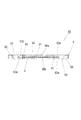
図1,2は、本実施例の燃料電池1のスタック8を示したものである。本実施例のスタック8は、薄板状の矩形の単位電池2を複数積層してなる。このスタック8には各単位電池2の周部を貫通する、四つの幅広なマニホールド6a〜6dを上下方向に形成している。このマニホールド6a〜6dは、各単位電池2の燃料極側に燃料ガス(水素)を供給するためのマニホールド6aや、空気極側に空気(酸素)を供給するマニホールド6b、各単位電池2で反応しなかった燃料ガスを燃料極側から排出するためのマニホールド6c、電池反応により生じた水分や反応後の空気を空気極側から排出するマニホールド6dよりなる。また、スタック8には、その周部を上下に貫通する位置決め孔7,7を形成し、この位置決め孔7に位置決め杆(図示省略)を挿通することにより、各単位電池2が整一に重なるように積層する。なお、本実施例の燃料電池1は、このスタック8以外に、前記マニホールド6a,6cに燃料ガスや空気を圧入するガス供給装置や集電装置等が装着されるが、これらは、公知の固体高分子型燃料電池と同様の構造を適宜使用可能であるため、説明を省略する。
Embodiments of the present invention will be described with reference to the drawings.
1 and 2 show a
本実施例の単位電池2は、図2,3に示すように、薄板状の発電部3の周縁を扁平なスペーサ5で囲繞して一体化した発電構造体10の両面に、中央にガス供給部40が形成されたセパレータ4,4を被着することによりなる。ここで、本実施例のセパレータ4は、その両面にガス供給部40が形成されており、上下ガス供給部40は夫々発電部3と当接することにより、隣接する単位電池2で共用されるものである。すなわち、本実施例のスタック8は、発電構造体10とセパレータ4とを交互に積層することにより、単位電池2が積層したスタック8が形成される。また、後述するように、本実施例にあっては、発電構造体10とセパレータ4との間には、発電部3の端部を厚み方向から支持する支持部材9を配設する。
As shown in FIGS. 2 and 3, the
また、発電部3は、電解質層31の両面にガス拡散電極30a,30bを接合してなるものであり、この発電部3の両ガス拡散電極30a,30bと対向するようにして、ガス供給部40が当接し、この当接部47を介して、ガス拡散電極30a,30bとセパレータ4とが電気的に接続する。また、ガス供給部40は、当接部47以外の部分を、ガス拡散電極30a,30bに沿ってガスが通過するガス流路溝41とする。このガス流路溝41を介して、燃料ガスや空気がガス拡散電極30a,30bへと夫々供給され、発電部3で生じた水分等がガス流路溝41側へ流出する。
The
ここで、本実施例にあっては、各単位電池2は、図3上側を燃料極、下側を空気極とするものであり、図3,4に示すように、発電部3の上面と当接するガス供給部40と、燃料ガスを流すマニホールド6a,6cとの間には、該ガス供給部40へ燃料ガスを循環させるためのガス連通路11a,11cを形成する。すなわち、本実施例の単位電池2にあっては、図3左側のマニホールド6aを流れる燃料ガスが、ガス連通路11aを通り、発電部3の上側(燃料極側)のガス流路溝41から燃料極側のガス拡散電極30aへと供給される。そして、未反応の燃料ガス等は、ガス連通路11cを通り、図3右側のマニホールド6cへと流出することとなる。
Here, in the present embodiment, each
一方、発電部3の空気極側と当接するガス供給部40と、空気の流れるマニホールド6b,6dとの間には、図4に示すように、該ガス供給部40へ空気を循環させるためのガス連通路11b,11dが形成される。そして、燃料極側と同様に、一側のマニホールド6bを流れる空気(酸素)がガス連通路11bを通って空気極側のガス流路溝41へと流入し、空気極側のガス拡散電極30bへと供給される。そして、電池反応によってガス拡散電極30b内に生じた水分や、未反応の空気等が、ガス連通路11dを通り、他側のマニホールド6dへと流出することとなる。
On the other hand, between the
また、本実施例の単位電池2にあっては、図2に示すように、燃料ガスを流すマニホールド6a,6cと、空気を流すマニホールド6b,6dの夫々が、各ガス供給部40を挟んで対向するように形成されており、発電部3の燃料極側と空気極側とに当接するガス供給部40,40では、夫々燃料ガスと空気とが相互に直交するように流れるようになっている。なお、本実施例の単位電池2にあっては、燃料極側と空気極側とは表裏で対称形状をなすものであり、両極の違いは、ガス供給部40に供給するガスの違い等、作動レベルのものであるため、その構造については、両極を区別することなく説明する。もちろん、これは一実施形態であり、本発明の実施形態としては、燃料極側と空気極側との構造を同一にする必要はなく、両極で非対称構造としても全く問題はない。
Further, in the
以下に、上記単位電池2を構成する、発電構造体10やセパレータ4の構成について説明する。
Below, the structure of the electric
発電構造体10は、薄板状の発電部3の周縁を扁平な絶縁性スペーサ5で囲繞してなる正方形状のものである。発電部3とスペーサ5とは、図5,6に示すように、発電部3の周縁部を、スペーサ5中央の収納開口50の内周域に形成された支持突部51と、全周に亘って係合することにより、分離不可能に組み付けられる。
The
発電部3は、図5,6に示すように、等厚な膜状をなす電解質層31の両面に、一対のガス拡散電極30a,30bを対向状に接合してなるものである。
As shown in FIGS. 5 and 6, the
ガス拡散電極30a,30bは、正方形に切り抜いた、厚さ1mm以下の多孔性カーボンペーパーよりなる。このカーボンペーパーの片面には白金を担持したカーボン粒子を全面に付着させて触媒層を形成している。このガス拡散電極30a,30bには、既存の固体高分子型燃料電池に用いられる触媒層とガス拡散導電層とからなるガス拡散電極を好適に使用可能であり、その構造、製造方法についての詳細は省略する。また、このガス拡散電極30a,30bについては、燃料極側と空気極側とで、略同形状のものを用いることが望ましいが、材質や触媒等については、両極の電池反応に適したもの用いることができる。
The
電解質層31の構成材料としては、リン酸カルシウムガラスから得たプロトン伝導ゲルを用いる。本実施例のプロトン伝導ゲルは、以下の工程により作製した。まず、リン酸がP2O5換算で50mol%の組成となるように炭酸カルシウムとリン酸の乾燥混合粉末を調製する。そして、この乾燥混合粉末を電気炉中で、1300℃・0.5時間の熱処理を行い、溶融させる。その後、溶融物をカーボン板上に流し出し、室温まで急冷しリン酸カルシウムガラスを得る。このリン酸カルシウムガラスを乳鉢で粒子の直径が10μm以下になるまで粉砕する。そして、得られたガラス粉末をプラスチックシャーレに入れ、等重量の蒸留水を加えて攪拌した後、施蓋して乾燥を防いだ状態で約3日間室温放置する。これにより、リン酸塩ガラス粉末が水と反応し、リン酸カルシウム分子鎖を水中に分散させてなる、柔軟なプロトン伝導ゲルを得る。そして、このプロトン伝導ゲルを、触媒層を内向きにした一対のガス拡散電極30a,30bの間に配し、プロトン伝導ゲルを薄膜状に成形・保持した状態で、熱処理(例えば温度90℃,湿度90%で6時間)を行い、プロトン伝導ゲルを硬化させて、プロトン伝導ゲルにより変形し難い電解質層31を構成すると共に、該電解質層31とガス拡散電極30a,30bとを分離不可能に接合させ、両者が一体化した発電部3を得る。
As a constituent material of the
スペーサ5は矩形のテフロン(登録商標)板を切削加工することによりなり、図5に示すように、その中央には発電部3を収納する収納開口50を成形する。収納開口50は、発電部3を整一に収納可能となるように、上記ガス拡散電極30a,30bと一致する正方形状に形成する。そして、図5,6に示すように、収納開口50の周縁には、内方へ突出し、ガス拡散電極30a,30bの周縁部と当接する支持突部51を周設する。この支持突部51は、図6に示すように、収納開口50の厚み方向に対して中央部分に設け、スペーサ5内周の縦断面を内向きの凸字形とする。
The
そして、スペーサ5の周部には、セパレータ4が被着する被着座55を表裏に形成する。この被着座55は、セパレータ4を発電構造体10に被着させた状態で、ガス供給部40とガス拡散電極30a,30bとが適当な力で当接し、発電部3に過剰な圧力がかからないように厚み規定を行う。また、収納開口50の各辺縁と対向する四位置には、通気開口52を形成する。この通気開口52は、収納開口50の辺縁と略同幅をなし、積層した際にマニホールド6a〜6dを構成する。また、周部の角位置には、位置決め孔7を構成するための貫通孔54,54も形成する。
Then, on the periphery of the
さらに、各通気開口52と収納開口50の各辺縁との間には、表裏に通気段溝53aと嵌合段溝53bとを形成する。通気段溝53aと嵌合段溝53bとは図5,6に示すように表裏で相互に対をなすように形成され、また、同一面では収納開口の周方向に沿って交互に並ぶように形成する。すなわち、スペーサ5の同一面上では、収納開口50を挟んで通気段溝53a同士、嵌合段溝53b同士が対向する。なお、本実施例においては、通気段溝53aと嵌合段溝53bとの形状に違いを持たせておらず、相互に共用することが可能となっている。
Further, a
また、発電部3とセパレータ4との組み付けは、発電部3の作製と同時に行う。すなわち、上記の発電部3の製造工程にあっては、柔軟なプロトン伝導ゲルを、一対のガス拡散電極30a,30bの間に配した後、プロトン伝導ゲルを硬化させることにより、発電部3を作製するものであるが、本実施例にあっては、プロトン伝導ゲルをガス拡散電極30a,30bの間に配すると同時に、両ガス拡散電極30a,30bの周縁部の間に、スペーサ5の支持突部51を介装させる。そして、この状態を治具等により保持したまま、プロトン伝導ゲルを硬化させ、電解質層31とガス拡散電極30a,30bとが密着した発電部3を作製すると共に、当該発電部3を、スペーサ5の支持突部51と係合させることにより、収納開口50に組み付けることができる。
Further, the assembly of the
セパレータ4は、図7〜9に示すように、正方形の一枚の金属板から製造し、その中央両面に、正方形のガス供給部40を形成すると共に、その周部の両面をスペーサ5の被着座55と密接する接合座面48とする。このセパレータ4を構成する材料としては、固体高分子型燃料電池のセパレータに用いられる、導電性や腐食性に優れたステンレス鋼やチタン等を好適に用いることができる。
As shown in FIGS. 7 to 9, the
ガス供給部40は、金属板の表裏に突成される複数の円形突起部42により形成する。この円形突起部42は、金属板をプレス成形することにより形成し、交互に異なる面に突出するものを、縦横に沿って配列する。そして、表裏両面のガス供給部40において、各円形突起部42の頂点付近を発電部3との当接部47とすると共に、該当接部47以外の部分を網状のガス流路溝41とする。このように、本実施例にあっては、両面のガス供給部40は、複数の円形突起部42の頂点付近で発電部3と当接させることにより、その当接部47を面方向で不連続なものとして、当接部47の間を縫うように網状のガス流路溝41を形成する。このため、ガス供給部40のガス流路溝41は面方向に沿って縦横にガスが通過可能であり、表裏のガス供給部40で、燃料ガスと空気とが相互に直交するように流すことができる。また、上述のように、かかる形状のガス供給部40は、金属板をプレス加工するだけ形成されるため、容易かつ低廉に作製できるという利点を有する。に形成することができる。なお、ガス供給部40と発電部3とは、夫々正方形をなし、積層した際に相互に積層方向で重なり、当接するようになっているが、ガス供給部40は発電部3の表面よりも僅かに小さくなっており、積層した際に、発電部3の端部が僅かに突出するようにしている。
The
ガス供給部40周囲の接合座面48には、ガス供給部40の各辺縁と対向する位置に、幅広な通気孔43を夫々形成する。この通気孔43は、ガス供給部40の対向する辺縁と略同幅で、かつスペーサ5の通気開口52と積層方向で一致する位置に形成し、この通気孔43と通気開口52を積層方向に交互に重ねることによりスタック8内にマニホールド6a〜6dを形成する。また、周部の角位置には、位置決め孔7を構成するための貫通孔46,46も形成する。
A
さらに各通気孔43とガス供給部40の各辺縁との間には、いずれか一面側に湾隆する方形の突隆部44を夫々形成し、各突隆部44の内部に、通気孔43とガス供給部40とを面方向に沿って連通する連通溝45を形成する。また、この突隆部44は、積層した際に、スペーサ5の通気段溝53aや嵌合段溝53bと積層方向で一致する形状に形成し、また、ガス供給部40を挟んで相互に対向するものを同一面側に、相互に隣接するもの同士は夫々異なる面側に湾隆させる。そして、セパレータ4とスペーサ5とを重ね合わせた際に、該突隆部44を隣接する嵌合段溝53bに嵌合させると共に、隣接する連通溝45と通気段溝53aとを接合させて、単位電池2の各ガス連通路11a〜11dを形成させる(図3,4参照)。
Furthermore, between each
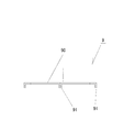
また、上述したように、本実施例の単位電池2にあっては、発電構造体10とセパレータ4との間に、発電部3の端部を厚み方向から支持する支持部材9を配設する。図10,11に示すように、この支持部材9は、成形した二片のステンレス鋼板を幅方向に接合してなるものであり、方形状の支持板90と、支持板90の中央及び側端に設けられた脚部91とで構成される。この支持部材9は、図7に示すように、連通溝45と略同じ大きさをなし、予めセパレータ4の各連通溝45の底面に脚部91を当接させた状態で固着される。そして、この支持部材9は、図3,4に示すように、セパレータ4と発電構造体10とを積層した状態で、その支持板90を通気段溝53aの底面に被着させると共に、支持板90の内側端で発電部3の端部を厚み方向から支持する(図3中のx)。
Further, as described above, in the
以上に詳述したセパレータ4や発電構造体10の構造を踏まえて、本実施例のスタック8の構造を詳述すると、本実施例の燃料電池1のスタック8は、セパレータ4と発電構造体10とを交互に重ね合わせて積層することにより構成する。そして、図3,4に示すように、スペーサ5の被着座55とセパレータ4の接合座面48とが接合することにより、発電部3両面のガス拡散電極30a,30bとセパレータ4のガス供給部40とが当接すると共に、セパレータ4の突隆部44が、スペーサ5の嵌合段溝53bに内嵌して閉塞すると共に、該突隆部44内部の連通溝45は、スペーサ5の通気段溝53aと接合して、マニホールド6a〜6dとガス供給部40とを連通するガス連通路11a〜11dを形成することとなる。従って、本実施例の単位電池2にあっては、セパレータ4のみならず、セパレータ4とスペーサ5の両方に形成した溝を積層方向に接合することによってガス連通路11を形成するものであり、従来構成よりも単位電池2の厚みに対して、より厚いガス流路を実現可能となっており、また、本実施例においては、ガス連通路11a〜11dの幅を正方形に形成したガス供給部40の各辺縁と略同幅にまで拡げることが可能となっている。このため、本実施例の燃料電池1にあっては、単位電池2の大きさに対して、従来よりも極めて広いガス連通路11a〜11dが形成されている。従って、同じ広さのガス連通路を有する単位電池であっても、本実施例の単位電池2にあっては、従来よりも薄型化することが可能となり、出力を低下させることなくスタック8をより高密度化することが可能となっている。
Based on the structure of the
また、上述したように、本実施例の単位電池2にあっては、ガス連通路11a〜11d内に、幅方向に亘り設けられた支持部材9により、発電部3の端部を厚み方向から支持するため(図3中のx部分)、ガス連通路11a〜11dを、ガス供給部40の各辺縁と略同じ幅としても、発電部3を変形させることなく安定して支持することが可能となっている。従って、本実施例では、機械的強度が弱くなるまで薄型化した発電部3であっても、好適に用いることが可能となっており、単位電池2をより薄型化させることができる。
Further, as described above, in the
さらには、本実施例のセパレータ4は、一枚の金属板からなるため薄型化に適し、また、その突隆部44やガス供給部40はプレス加工により形成できるため、金属板を切削加工することなく簡単な工程により製造することができる。
Furthermore, since the
以上のように、本実施例の燃料電池にあっては、単位電池の構成に対して厚み・幅方向共に広いガス連通路が形成されているため、単位電池2を薄型化しても、十分なガスの循環を行うことが可能となり、出力を低下させることなく、燃料電池のスタックを高密度化することが可能となる。 As described above, in the fuel cell according to the present embodiment, the gas communication passage that is wide in both the thickness and the width direction is formed with respect to the configuration of the unit cell. Gas circulation can be performed, and the density of the fuel cell stack can be increased without lowering the output.
なお、本発明は、上記実施例の構成や方法に限定したものではなく、本発明の趣旨の範囲内で適宜変更可能である。例えば、セパレータ4の連通溝45や、スペーサ5の通気段溝53a、嵌合段溝53bの形状は、本実施例の形状に限らず適宜変更可能である。例えば、上記実施例では、連通溝45と通気段溝53aとは略一致するようにしているが、これらの接合により厚みのあるガス連通路を形成できる限りにおいては、不完全一致であっても構わない。
In addition, this invention is not limited to the structure and method of the said Example, In the range of the meaning of this invention, it can change suitably. For example, the shapes of the
また、本発明は、プロトン伝導ゲルを電解質として用いた燃料電池の単位電池を薄型化と目的として為されたもので、上述の実施例においても、電解質層の構成材料としてプロトン伝導ゲルを用いているが、上記実施例同様の発電構造体10を形成可能なものであれば、電解質層に種々の材料を用いることが可能である。また、その際には、発電部3とスペーサ5とは必ずしも分離不可能な形で一体化させる必要もない。
Further, the present invention was made for the purpose of reducing the thickness of a unit cell of a fuel cell using a proton conductive gel as an electrolyte. Also in the above-described embodiment, the proton conductive gel is used as a constituent material of the electrolyte layer. However, various materials can be used for the electrolyte layer as long as the
さらに、従来の固体高分子型燃料電池には、スタック内に冷却水を循環させる構造を有するものが知られているが、本発明の燃料電池にあっても、各単位電池を貫通するように、冷却水を循環させるマニホールドをスタックに形成したり、冷却水の流路を備える単位電池を何枚かに一枚介挿したりするなど、既存の冷却機構を適宜組み合わせることが可能である。また、上記実施例には記述していないが、本発明のセパレータと発電構造体の間には、ガス漏れ防止のため、ガスケットやグリス等を適宜に充填することが望ましく、本発明の実施形態には、かかるガス漏れ防止構造も適宜加え得る。 Further, a conventional polymer electrolyte fuel cell is known that has a structure in which cooling water is circulated in the stack. However, even in the fuel cell of the present invention, the unit cell penetrates each unit cell. It is possible to combine existing cooling mechanisms as appropriate, such as forming a manifold for circulating the cooling water in the stack or inserting several unit cells each having a cooling water flow path. Further, although not described in the above embodiment, it is desirable to appropriately fill a gasket, grease or the like between the separator of the present invention and the power generation structure in order to prevent gas leakage. In addition, such a gas leakage prevention structure may be added as appropriate.
1 燃料電池
2,102 単位電池
3,103 発電部
4,104 セパレータ
5,105 スペーサ
6a〜6d,106 マニホールド
7 位置決め孔
8 スタック
9 支持部材
10,110 発電構造体
11a〜11d,111 ガス供給路
30a,30b,130 ガス拡散電極
31,131 電解質層
40 ガス供給部
41 ガス流路溝
42 円形突起部
43 通気孔
44 突隆部
45 連通溝
46 貫通孔
47 当接部
48 接合座面
50 収納開口
51,151 支持突部
52 通気開口
53a 通気段溝
53b 嵌合段溝
54 貫通孔
55 被着座
90 支持板
91 脚部
DESCRIPTION OF
Claims (3)
発電部と当接する当接部とガス流路溝とを有するガス供給部が中央に形成され、該ガス供給部を発電部に対向するようにして、発電構造体上に被着するセパレータと
を複数積層してなる燃料電池であって、
発電部は、方形状をなすものであり、
スペーサは、その中央に、該発電部が整一に収納される方形状の収納開口が形成され、
かつ収納開口の外周部には、セパレータが被着する被着座が表裏に形成され、
また、収納開口の各辺縁と対向する四位置に夫々幅広な通気開口が形成され、
さらに、各通気開口と、収納開口の各辺縁との間には、ガスが通過する通気段溝と、セパレータにより閉塞される嵌合段溝とが、表裏で相互に対を成し、かつ、同一面では収納開口の周方向に沿って交互に並ぶように形成されており、
セパレータは、中央の表裏に夫々方形状のガス供給部が形成され、かつその表裏周縁をスペーサの被着座に当接して装着される金属板よりなり、
かつその周部には、ガス供給部の各辺縁と対向し、かつスペーサの各通気開口と積層方向で一致する、四つの幅広な通気孔が夫々形成され、
さらにガス供給部の各辺縁と各通気孔との間には、いずれか一面側へ湾隆し、スペーサの嵌合段溝と嵌合する突隆部が夫々形成され、各突隆部内には、通気孔とガス供給部とに面方向に沿って連通し、スペーサの通気段溝と接合する連通溝が形成されていることを特徴とする燃料電池。 A power generation structure comprising a thin plate-shaped power generation unit formed by bonding gas diffusion electrodes to both surfaces of the electrolyte layer, and an insulating spacer surrounding the periphery of the power generation unit;
A gas supply portion having a contact portion that contacts the power generation portion and a gas flow channel groove is formed in the center, and a separator that is deposited on the power generation structure with the gas supply portion facing the power generation portion. A fuel cell comprising a plurality of stacked layers,
The power generation part has a rectangular shape,
In the center of the spacer, a square-shaped storage opening in which the power generation unit is stored uniformly is formed,
And on the outer periphery of the storage opening, a seat to which the separator is attached is formed on the front and back,
In addition, a wide ventilation opening is formed at each of the four positions facing each edge of the storage opening,
Furthermore, between each ventilation opening and each edge of the storage opening, a ventilation step groove through which gas passes and a fitting step groove closed by the separator are mutually paired, and In the same plane, it is formed to be alternately arranged along the circumferential direction of the storage opening,
The separator is made of a metal plate that is formed with a rectangular gas supply part on the front and back of the center, and the front and back edges of the separator are in contact with the spacer seat,
And in the periphery, four wide vent holes are formed, which face each edge of the gas supply section and coincide with each vent opening of the spacer in the stacking direction, respectively.
Furthermore, between each edge of the gas supply section and each vent hole, a ridge is formed on either side to be fitted with the fitting step groove of the spacer. Is a fuel cell characterized in that a communication groove is formed which communicates with the vent hole and the gas supply section along the surface direction and joins the vent step groove of the spacer.
It is provided in the inside of the ventilation step groove and the communication groove that are joined to each other in the width direction, and includes a support member that abuts the inner end of the ventilation step groove side with respect to the end portion of the power generation unit from the thickness direction. The fuel cell according to claim 1 or 2.
Priority Applications (3)
| Application Number | Priority Date | Filing Date | Title |
|---|---|---|---|
| JP2004036083A JP4620361B2 (en) | 2004-02-13 | 2004-02-13 | Fuel cell |
| US10/597,890 US20070105002A1 (en) | 2004-02-13 | 2005-02-03 | Fuel battery |
| PCT/JP2005/001575 WO2005078837A1 (en) | 2004-02-13 | 2005-02-03 | Fuel battery |
Applications Claiming Priority (1)
| Application Number | Priority Date | Filing Date | Title |
|---|---|---|---|
| JP2004036083A JP4620361B2 (en) | 2004-02-13 | 2004-02-13 | Fuel cell |
Publications (3)
| Publication Number | Publication Date |
|---|---|
| JP2005228595A JP2005228595A (en) | 2005-08-25 |
| JP2005228595A5 JP2005228595A5 (en) | 2007-03-15 |
| JP4620361B2 true JP4620361B2 (en) | 2011-01-26 |
Family
ID=34857712
Family Applications (1)
| Application Number | Title | Priority Date | Filing Date |
|---|---|---|---|
| JP2004036083A Expired - Fee Related JP4620361B2 (en) | 2004-02-13 | 2004-02-13 | Fuel cell |
Country Status (3)
| Country | Link |
|---|---|
| US (1) | US20070105002A1 (en) |
| JP (1) | JP4620361B2 (en) |
| WO (1) | WO2005078837A1 (en) |
Families Citing this family (3)
| Publication number | Priority date | Publication date | Assignee | Title |
|---|---|---|---|---|
| JP2009099311A (en) * | 2007-10-15 | 2009-05-07 | Equos Research Co Ltd | Fuel cell stack |
| US8137856B2 (en) * | 2009-02-13 | 2012-03-20 | Hitachi, Ltd. | Fuel cell |
| TWI384680B (en) | 2010-01-21 | 2013-02-01 | Ind Tech Res Inst | Fluid flow plate of a fuel cell |
Citations (5)
| Publication number | Priority date | Publication date | Assignee | Title |
|---|---|---|---|---|
| JPH07220743A (en) * | 1994-01-27 | 1995-08-18 | Kansai Electric Power Co Inc:The | Fuel cell, its bipolar plate and manufacture of bipolar plate |
| JPH08287928A (en) * | 1995-04-17 | 1996-11-01 | Sanyo Electric Co Ltd | Flat fuel cell and its manufacture |
| JPH0955217A (en) * | 1995-08-10 | 1997-02-25 | Tanaka Kikinzoku Kogyo Kk | Gasket for fuel cell and stacked fuel cell |
| JP2000223137A (en) * | 1999-01-29 | 2000-08-11 | Aisin Takaoka Ltd | Fuel cell and separator |
| JP2002260690A (en) * | 2001-02-23 | 2002-09-13 | General Motors Corp <Gm> | Stamped bipolar plate for pem fuel cell stack |
Family Cites Families (1)
| Publication number | Priority date | Publication date | Assignee | Title |
|---|---|---|---|---|
| JPH07207423A (en) * | 1994-01-17 | 1995-08-08 | Nippon Steel Corp | Production of case hardening steel parts |
-
2004
- 2004-02-13 JP JP2004036083A patent/JP4620361B2/en not_active Expired - Fee Related
-
2005
- 2005-02-03 US US10/597,890 patent/US20070105002A1/en not_active Abandoned
- 2005-02-03 WO PCT/JP2005/001575 patent/WO2005078837A1/en active Application Filing
Patent Citations (5)
| Publication number | Priority date | Publication date | Assignee | Title |
|---|---|---|---|---|
| JPH07220743A (en) * | 1994-01-27 | 1995-08-18 | Kansai Electric Power Co Inc:The | Fuel cell, its bipolar plate and manufacture of bipolar plate |
| JPH08287928A (en) * | 1995-04-17 | 1996-11-01 | Sanyo Electric Co Ltd | Flat fuel cell and its manufacture |
| JPH0955217A (en) * | 1995-08-10 | 1997-02-25 | Tanaka Kikinzoku Kogyo Kk | Gasket for fuel cell and stacked fuel cell |
| JP2000223137A (en) * | 1999-01-29 | 2000-08-11 | Aisin Takaoka Ltd | Fuel cell and separator |
| JP2002260690A (en) * | 2001-02-23 | 2002-09-13 | General Motors Corp <Gm> | Stamped bipolar plate for pem fuel cell stack |
Also Published As
| Publication number | Publication date |
|---|---|
| US20070105002A1 (en) | 2007-05-10 |
| JP2005228595A (en) | 2005-08-25 |
| WO2005078837A1 (en) | 2005-08-25 |
Similar Documents
| Publication | Publication Date | Title |
|---|---|---|
| US6818338B2 (en) | Fuel cell assembly | |
| JP4505204B2 (en) | Fuel cell system | |
| US11038190B2 (en) | Membrane electrode assembly, fuel cell comprising assembly of this type and motor vehicle comprising said fuel cell | |
| JP2002203578A (en) | High polymer electrolyte fuel cell | |
| JP4828841B2 (en) | Fuel cell | |
| JP2012212678A (en) | Fuel cell | |
| WO2003105265A1 (en) | Liquid fuel feed type fuel cell | |
| JP2002352817A (en) | Polymer electrolyte fuel cell | |
| JP3696230B1 (en) | Fuel cell | |
| JP4620361B2 (en) | Fuel cell | |
| JP5143336B2 (en) | Polymer electrolyte fuel cell | |
| KR101127028B1 (en) | Fuel cell | |
| JP4078251B2 (en) | Fuel cells and small electrical equipment | |
| JP2000251902A (en) | Gas separator for fuel cell, its manufacture and fuel cell | |
| JP4511610B2 (en) | Fuel cell and manufacturing method thereof | |
| JPH08287934A (en) | Fuel cell | |
| CN111837275B (en) | Fuel cell and fuel cell stack including the same | |
| JP4304955B2 (en) | Solid polymer electrolyte fuel cell | |
| JP2002093434A (en) | Electrolyte layer/electrode joint body and fuel cell | |
| JP2000012053A (en) | Solid high-polymer electrolyte-type fuel cell | |
| JP2005216535A (en) | Fuel cell | |
| JP2007012382A (en) | Separator and fuel cell equipped with separator | |
| WO2009145090A1 (en) | Fuel cell and method of manufacture thereof | |
| JP4440088B2 (en) | Fuel cell | |
| JP2009224275A (en) | Separator for fuel cell, its manufacturing method, and fuel cell |
Legal Events
| Date | Code | Title | Description |
|---|---|---|---|
| A521 | Request for written amendment filed |
Free format text: JAPANESE INTERMEDIATE CODE: A523 Effective date: 20070130 |
|
| A621 | Written request for application examination |
Free format text: JAPANESE INTERMEDIATE CODE: A621 Effective date: 20070130 |
|
| TRDD | Decision of grant or rejection written | ||
| A01 | Written decision to grant a patent or to grant a registration (utility model) |
Free format text: JAPANESE INTERMEDIATE CODE: A01 Effective date: 20100928 |
|
| A01 | Written decision to grant a patent or to grant a registration (utility model) |
Free format text: JAPANESE INTERMEDIATE CODE: A01 |
|
| A61 | First payment of annual fees (during grant procedure) |
Free format text: JAPANESE INTERMEDIATE CODE: A61 Effective date: 20101028 |
|
| FPAY | Renewal fee payment (event date is renewal date of database) |
Free format text: PAYMENT UNTIL: 20131105 Year of fee payment: 3 |
|
| R150 | Certificate of patent or registration of utility model |
Free format text: JAPANESE INTERMEDIATE CODE: R150 |
|
| LAPS | Cancellation because of no payment of annual fees |