JP4620249B2 - Spindle unit for drilling in the production of fiber reinforced composite materials - Google Patents
Spindle unit for drilling in the production of fiber reinforced composite materials Download PDFInfo
- Publication number
- JP4620249B2 JP4620249B2 JP2000551910A JP2000551910A JP4620249B2 JP 4620249 B2 JP4620249 B2 JP 4620249B2 JP 2000551910 A JP2000551910 A JP 2000551910A JP 2000551910 A JP2000551910 A JP 2000551910A JP 4620249 B2 JP4620249 B2 JP 4620249B2
- Authority
- JP
- Japan
- Prior art keywords
- tool
- shaft
- drilling
- cutting tool
- axis
- Prior art date
- Legal status (The legal status is an assumption and is not a legal conclusion. Google has not performed a legal analysis and makes no representation as to the accuracy of the status listed.)
- Expired - Fee Related
Links
- 238000005553 drilling Methods 0.000 title claims description 39
- 238000004519 manufacturing process Methods 0.000 title claims description 5
- 239000000463 material Substances 0.000 title description 18
- 239000003733 fiber-reinforced composite Substances 0.000 title description 6
- 238000005520 cutting process Methods 0.000 claims description 40
- 238000003754 machining Methods 0.000 claims description 31
- 230000007246 mechanism Effects 0.000 claims description 25
- 238000000034 method Methods 0.000 description 19
- 239000010410 layer Substances 0.000 description 11
- 239000002131 composite material Substances 0.000 description 10
- 239000000835 fiber Substances 0.000 description 9
- 239000000047 product Substances 0.000 description 8
- 230000032798 delamination Effects 0.000 description 6
- 238000000227 grinding Methods 0.000 description 5
- 229920000642 polymer Polymers 0.000 description 4
- 230000008901 benefit Effects 0.000 description 3
- RTAQQCXQSZGOHL-UHFFFAOYSA-N Titanium Chemical compound [Ti] RTAQQCXQSZGOHL-UHFFFAOYSA-N 0.000 description 2
- 238000013459 approach Methods 0.000 description 2
- 230000004323 axial length Effects 0.000 description 2
- 238000005516 engineering process Methods 0.000 description 2
- 239000011159 matrix material Substances 0.000 description 2
- 229920001169 thermoplastic Polymers 0.000 description 2
- 239000004416 thermosoftening plastic Substances 0.000 description 2
- 239000010936 titanium Substances 0.000 description 2
- 229910052719 titanium Inorganic materials 0.000 description 2
- OKTJSMMVPCPJKN-UHFFFAOYSA-N Carbon Chemical compound [C] OKTJSMMVPCPJKN-UHFFFAOYSA-N 0.000 description 1
- 229910052782 aluminium Inorganic materials 0.000 description 1
- XAGFODPZIPBFFR-UHFFFAOYSA-N aluminium Chemical compound [Al] XAGFODPZIPBFFR-UHFFFAOYSA-N 0.000 description 1
- 150000001408 amides Chemical class 0.000 description 1
- 229910052799 carbon Inorganic materials 0.000 description 1
- 230000008859 change Effects 0.000 description 1
- 230000000295 complement effect Effects 0.000 description 1
- 238000007796 conventional method Methods 0.000 description 1
- 238000001816 cooling Methods 0.000 description 1
- 238000013461 design Methods 0.000 description 1
- 238000006073 displacement reaction Methods 0.000 description 1
- 239000012636 effector Substances 0.000 description 1
- 239000002657 fibrous material Substances 0.000 description 1
- 239000012467 final product Substances 0.000 description 1
- 239000011521 glass Substances 0.000 description 1
- 239000002648 laminated material Substances 0.000 description 1
- 239000007788 liquid Substances 0.000 description 1
- 229910052751 metal Inorganic materials 0.000 description 1
- 239000002184 metal Substances 0.000 description 1
- 239000007769 metal material Substances 0.000 description 1
- 238000003801 milling Methods 0.000 description 1
- 238000012986 modification Methods 0.000 description 1
- 230000004048 modification Effects 0.000 description 1
- 239000002861 polymer material Substances 0.000 description 1
- 230000008569 process Effects 0.000 description 1
- 239000011241 protective layer Substances 0.000 description 1
- 230000002787 reinforcement Effects 0.000 description 1
- 239000012779 reinforcing material Substances 0.000 description 1
- 238000000926 separation method Methods 0.000 description 1
- 229910001220 stainless steel Inorganic materials 0.000 description 1
- 239000010935 stainless steel Substances 0.000 description 1
- 239000000126 substance Substances 0.000 description 1
- 239000002344 surface layer Substances 0.000 description 1
- 229920001187 thermosetting polymer Polymers 0.000 description 1
- 238000012546 transfer Methods 0.000 description 1
Images
Classifications
-
- B—PERFORMING OPERATIONS; TRANSPORTING
- B23—MACHINE TOOLS; METAL-WORKING NOT OTHERWISE PROVIDED FOR
- B23Q—DETAILS, COMPONENTS, OR ACCESSORIES FOR MACHINE TOOLS, e.g. ARRANGEMENTS FOR COPYING OR CONTROLLING; MACHINE TOOLS IN GENERAL CHARACTERISED BY THE CONSTRUCTION OF PARTICULAR DETAILS OR COMPONENTS; COMBINATIONS OR ASSOCIATIONS OF METAL-WORKING MACHINES, NOT DIRECTED TO A PARTICULAR RESULT
- B23Q5/00—Driving or feeding mechanisms; Control arrangements therefor
- B23Q5/22—Feeding members carrying tools or work
- B23Q5/32—Feeding working-spindles
-
- B—PERFORMING OPERATIONS; TRANSPORTING
- B23—MACHINE TOOLS; METAL-WORKING NOT OTHERWISE PROVIDED FOR
- B23Q—DETAILS, COMPONENTS, OR ACCESSORIES FOR MACHINE TOOLS, e.g. ARRANGEMENTS FOR COPYING OR CONTROLLING; MACHINE TOOLS IN GENERAL CHARACTERISED BY THE CONSTRUCTION OF PARTICULAR DETAILS OR COMPONENTS; COMBINATIONS OR ASSOCIATIONS OF METAL-WORKING MACHINES, NOT DIRECTED TO A PARTICULAR RESULT
- B23Q1/00—Members which are comprised in the general build-up of a form of machine, particularly relatively large fixed members
- B23Q1/25—Movable or adjustable work or tool supports
- B23Q1/44—Movable or adjustable work or tool supports using particular mechanisms
- B23Q1/48—Movable or adjustable work or tool supports using particular mechanisms with sliding pairs and rotating pairs
- B23Q1/4828—Movable or adjustable work or tool supports using particular mechanisms with sliding pairs and rotating pairs a single rotating pair followed parallelly by a single sliding pair
-
- Y—GENERAL TAGGING OF NEW TECHNOLOGICAL DEVELOPMENTS; GENERAL TAGGING OF CROSS-SECTIONAL TECHNOLOGIES SPANNING OVER SEVERAL SECTIONS OF THE IPC; TECHNICAL SUBJECTS COVERED BY FORMER USPC CROSS-REFERENCE ART COLLECTIONS [XRACs] AND DIGESTS
- Y10—TECHNICAL SUBJECTS COVERED BY FORMER USPC
- Y10T—TECHNICAL SUBJECTS COVERED BY FORMER US CLASSIFICATION
- Y10T408/00—Cutting by use of rotating axially moving tool
- Y10T408/83—Tool-support with means to move Tool relative to tool-support
- Y10T408/85—Tool-support with means to move Tool relative to tool-support to move radially
- Y10T408/854—Tool-support with means to move Tool relative to tool-support to move radially to move eccentrically mounted Tool
-
- Y—GENERAL TAGGING OF NEW TECHNOLOGICAL DEVELOPMENTS; GENERAL TAGGING OF CROSS-SECTIONAL TECHNOLOGIES SPANNING OVER SEVERAL SECTIONS OF THE IPC; TECHNICAL SUBJECTS COVERED BY FORMER USPC CROSS-REFERENCE ART COLLECTIONS [XRACs] AND DIGESTS
- Y10—TECHNICAL SUBJECTS COVERED BY FORMER USPC
- Y10T—TECHNICAL SUBJECTS COVERED BY FORMER US CLASSIFICATION
- Y10T409/00—Gear cutting, milling, or planing
- Y10T409/30—Milling
- Y10T409/303752—Process
- Y10T409/303808—Process including infeeding
-
- Y—GENERAL TAGGING OF NEW TECHNOLOGICAL DEVELOPMENTS; GENERAL TAGGING OF CROSS-SECTIONAL TECHNOLOGIES SPANNING OVER SEVERAL SECTIONS OF THE IPC; TECHNICAL SUBJECTS COVERED BY FORMER USPC CROSS-REFERENCE ART COLLECTIONS [XRACs] AND DIGESTS
- Y10—TECHNICAL SUBJECTS COVERED BY FORMER USPC
- Y10T—TECHNICAL SUBJECTS COVERED BY FORMER US CLASSIFICATION
- Y10T82/00—Turning
- Y10T82/12—Radially moving rotating tool inside bore
Landscapes
- Engineering & Computer Science (AREA)
- Mechanical Engineering (AREA)
- Drilling And Boring (AREA)
- Milling Processes (AREA)
Description
【0001】
発明の背景
1.発明の技術分野
本発明は、繊維強化複合材料とか、金属とか、それらの組合せとかの、平らなまたは曲ったシートを含む製作物に、穴または凹部を加工するための方法および主軸ユニットに関する。
【0002】
2.関連技術の説明
宇宙空間および他の用途における構造物は、しばしば、アルミニウム、チタニウム、ステンレス鋼、および繊維強化複合材料のような異なる材料の薄い曲ったシェルで作られている。構造物への用途において、異なる構成要素がしばしばボルト継手を使用して係合される。宇宙空間構造物用のボルト穴は一般的に4−20mmの直径で、構造物の完全さを確保するために高品質を要求される。
【0003】
穴への要求事項は寸法と損傷に関するものである。寸法への要求事項は、例えば、円筒状穴の直径と、穴の円筒部分の高さと、きくぎり(countersink)の直径および角度と、粗さと、表面の公称方向のアラインメントとを含んでいる。損傷に関する要求事項は、数ある中でも、許容ばり(burr)高さと、面仕上げと、繊維強化複合材料における許容層剥離(delamination)とを含んでいる。
【0004】
問題はとくに、繊維強化材料の穴あけの際におきる。ポリマー(polymer)複合材料は1950年代から一般に公知である。これらの材料は被覆し、接合したポリマーからなり、熱可塑性プラスチックまたは熱硬化性プラスチックのどちらかで、通常は繊維〔ガラス、または炭素、またはアミドファイバー(amide fiber)〕とともにマトリックスとして引合に出され、それらは補強材料と見なされてもよい。繊維は、連続していて特定の方向を向いているか、比較的短かくてマトリックス(matrix)の中で不揃いに配列されていてもよい。
連続していて一定の方向を向いている繊維を有する複合材料は、とくに重量に対する強化および剛性に関して、従来のポリマー材料および金属材料に勝る機械的性質を有する製品となる。短かい繊維を有する複合材料は、むしろ性能を要求されないところに用途を見出している。複合材料の広い範囲への使用をさまたげている一つの因子は、切削機械加工の有効な方法がないからである。複合材料の物理的、化学的性質は、公知の機械加工方法を一般的に使用しても成功しないことを意味している。
【0005】
複合材料からなる製品は、種々の目的のためにしばしば穴を含んでいる。これらの穴は、例えばサービスライン(service line)の布設、または組立、または検査を可能にするために必要とされるかも知れない。ボルト穴が穴の重要な部類となる。従来の用途における構造物は、最終製品とするために、しばしば一体に結合される構成要素から組立てられる。結合の目的は、荷重を一方の構造要素からもう一方に伝達するためのものである。結合の一つの共通な形式はボルト継手で、荷重はボルト内における剪断荷重または引張荷重により伝達される。ボルト継手の強度は穴の品質と精度により著しい影響を受ける。説明は、ポリマーベースの繊維強化複合材料に穴あけ加工する際の、特に三つの問題分野について行なう。
【0006】
1.薄層間の低強度。薄層複合材料を機械加工する際、層が薄層間の低強度のために分離(層間はく離)の危険がある。広範囲にわたる層間はく離損傷は薄層の強度にとって致命的となる。
2.熱可塑性プラスチックの低耐熱性および低耐冷却性。機械加工の間に発生する熱はマトリックスを柔軟にし、工具をブロックして、機械加工の継続を不可能にする。穴の良い品質を実現するために、工具/穴の縁部を効果的に冷却する必要があり、切削により除去された材料(チップ、裂片、研削くず)は連続的に穴から取り除かれねばならない。
3.繊維における高耐摩耗性。繊維複合材料の切削機械加工は、繊維材料の良好な耐摩耗特性のために、工具に苛酷な摩耗が生ずる。このことは、穴を高精度で加工する際、摩耗による高コストがかかる。
【0007】
薄層複合材料に穴あけ加工するために使用される方法は、伝統的なドリル加工、穴ぐり加工、フライス加工、のこぎり加工、研削加工である。現在それらが適用されると、これらの穴あけ加工方法に付随する問題は以下のとうりであって、それらの加工方法は技術的/経済的観点からの種々の理由により、十分に効果的ではない。
【0008】
摩耗による高コストは、高精度が要求される切削加工に附随する一般的な問題である。ドリル加工または穴ぐり加工の際、工具の入口側と出口側の両側において、層間はく離損傷を回避することを確実にするために、多くの注意を払わねばならない。特殊工具が、要求される穴の品質を実現するために必要とされ、特別な加工方法が開発されねばならない。薄層の工具の出口側における広範囲の層間はく離を回避するために、部分的な横方向の圧力が穴の縁部の周囲に加えられねばならない。もう一つの今までに開示された工具の出口側を損傷から防止する方法は、薄層に追加の保護層を備えることである。
【0009】
のこぎり加工は、高精度の要求がある穴あけ加工として明らかに不適切な方法である。研削による穴あけ加工の際に、円筒形状の環状ボデーが使用され、機械加工用端部は耐摩耗表面層が塗付されている。穴は、まず研削用ボデーを回転すると同時に、材料の表面を直交して研削することにより加工される。
【0010】
この観点から以下のことが指摘されていて、穴あけ機械加工方法において、回転軸の周囲を回転的に駆動されるボデーは、また軌道運動をする(すなわち、回転軸は側面が穴の縁部に対して移動することができるように配置されている)ことはよく知られている。スエーデン特許第173899号(SE173899)は、主軸の周囲を偏心的に回転する工具搬送器を有していて、工具搬送器と主軸との距離がガイド装置により決定されており、そのガイド装置は工具搬送器と共に主軸の周囲を回転する。搬送器と共に回転するガイド装置は、主軸に垂直に配置されていて、工具ホルダーに対してその周囲を回転可能なカムとなっており、工具ホルダーは直接カムのガイディング輪郭に齢合している。本発明における利点は、とりわけ、ガイド装置として自由遊びがなく省スペースなことである。しかしながら、工具ホルダーの回転軸と偏心回転軸との間のオフセットは、カムギアーのサイズにより固定され決定される。このようにオフセットは、ヘッド内部のカムギアーを取り替えることなしには、容易に調節することができない。スエーデン特許第382506号(SE382506)は、静止した製作物に穴あけ加工するための、回転可能に駆動し直結された切削工具を開示していて、製作物の穴は円錐状の食付きチャンファーを備えていてもよい。
【0011】
米国特許第5641252号(Eriksson他)において、技術的に非常に進歩した段階となる、繊維強化複合材料における穴の機械加工方法が開示されている。穴の中心軸が、製作物の表面の前もって決定された点を貫通していて、その点の直ぐ近傍における繊維の長手方向に対してある方向に向けられている。材料は、工具を自分自身の軸の周囲だけではなく、中心軸の周囲に偏心的にも、軸方向の運動および回転をさせることにより、軸方向と半径方向の両方に同時に機械加工される。この方法は、複合材料に層間はく離を生ずることなく穴を機械加工することを可能にしている。
【0012】
宇宙空間用および関連する構造物は、一般に異なる材料を一体に積み上げて作られる。特別な問題が、異なる材料(積層材料)の数層を含む構造物に同時にドリル加工する際発生する。そのような問題は、穴に近い層間におけるばりと、層〔液体シム(liquid shim)〕間の接合材料の損傷とを含んでいる。従来の技術を使用した穴あけ加工は、工具をすぐ摩耗させる熱を発生する。この問題は、とくにチタニウムに穴あけ加工する際著しいものである。
【0013】
在来のロボットアーム付きスピンドルを取り付け、切削用工具に動きを指令するロボットの制御装置を使用することは公知である。問題は、穴あけ結果の精度および品質が、ロボットの機構と、ロボットに附帯している制御装置とにより制限されることであって、その制御装置は重量の重いロボットアームを移動し位置決めするべく設計されている。このように、ロボットの機構と制御装置とにおける、精度および性能は、例えば必要とされる動きで、高速度下において高精度のファスナー用穴を機械加工するには十分でない。
【0014】
本発明の概要
本発明は、今までに開示された方法に関連する欠点と制限を排除し、強度低減の損傷およびばりのない合理的でかつ費用効果のある穴の加工を可能とし、そうすることにより、品質の良い穴を保証している。本発明は、第一回転軸を持つ切削用工具を有する、製作物への穴あけ加工用主軸ユニットを提供するものであって、その切削用工具がまた、機械式駆動要素を使用して調節可能な、第二偏心回転軸の周囲を移動可能である。主軸ユニットは、エンドエフェクタ(end effector)を位置決めし方位決めするのに使用される、ロボットアームに取り付けられてもよくて、精密な機械加工は主軸ユニットにより制御される。
【0015】
本発明における一つの形態において、製作物の穴あけ機械加工装置が、主軸の周囲を回転可能なスピンドルモーターを含んでいる。スピンドルモーターは、主軸にほぼ平行な工具軸を有する工具ホルダーを含んでいる。工具ホルダーは工具軸の周囲を回転可能である。軸方向アクチュエーターは、スピンドルモーターを主軸と工具軸との各々にほぼ平行な軸送り方向に移動するべく、形造られている。半径方向アクチュエーターは、主軸と工具軸との間の半径方向距離を調節するべく、形造られている。
【0016】
偏心回転運動は、厳密な回転運動すなわち、中心軸と工具の回転軸との間における、一定または連続的に変化する距離により達成される。
【0017】
本装置は一般に公知の機械に比較して多くの利点を有している:
1.装置は、切削用工具の回転軸と、偏心回転軸との間の半径方向オフセットを、どのような部品をも交換することなく容易に調節することを可能にしている。
2.装置は、ロボットアームの制御装置を使用することにより達成できるよりも、高精度で高品質の穴あけ生産を可能としている。
3.方法は、公差の厳しい穴あけ生産を可能にしている。穴あけの寸法精度は、中心軸に対する工具の位置決め精度によりほぼ決定される。工具の幾何学的形状への要求事項は特に厳しいものではなく、その一方で、すべての個々の工具が使用前に簡単に較正されているからである。
【0018】
添付図面とともに本発明における実施の形態の以下の説明を参照することにより、前述したそして他の、本発明における形態および利点と、それらを実現する方法とがより明確になり、さらに本発明がより理解される。
なお、図面をとうして、同一符号は同一部品を示めしている。ここでの説明は、一例として本発明における好適な実施の形態で例示しているが、本説明が本発明におけるどのような範囲をも制限するものではない。
【0019】
発明の詳細な説明
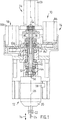
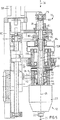
図1において、主軸ユニット10がスピンドルモーター12と、半径方向オフセット機構14と軸送り機構16と、偏心回転機構18とを含んでいる。
【0020】
スピンドルモーター12は、本体20と、回転中における切削用工具24を咬合するために形造られた回転工具ホルダー22とを、含んでいる。工具軸26を規定する切削用工具24が、製作物における穴(図示されていない)あけ用に設計されてもよくて、穴の直径は切削用工具24の直径より大きい。穴は、例えば米国特許第5,641,252号(Eriksson他)に開示された方法を使用して機械加工されてもよい。スピンドルモーター12がまた導管28を含んでいてもよくて、その導管を介してスピンドルモーター12は、電気動力、または空気動力、または油圧動力を供給されてもよい。
【0021】
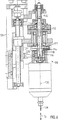
スピンドルモーター12の頂部が、止めピン32(図2)を有する環状アタッチメント30に固定的に取り付けられていて、その止めピンはアタッチメントの背面から半径方向に伸長している。止めピン32は、主軸ユニット10のブラケット36における溝穴34の中に摺動可能に嵌合されている。止めピン32は、どちらの方向、特に工具軸26に直交する方向において、溝穴34内での動きにおける自由度に制限がある。溝穴34内で摺動するけれども、止めピン32の長手方向軸38が背面方向に伸長していて、それによりスピンドルモーター本体20の一定の方向を保持し、本体20は常に一定の方向を向いている。このスピンドルモーター本体20の一定方向の保持は、スピンドルモーター12に動力を供給することを容易にしている。
【0022】
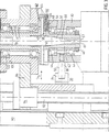
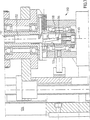
図3における拡大図に示めされている半径方向オフセット機構14は、内部にテーパー付きの摺動ブロック40を含んでいて、中空チューブ42が環状アタッチメント30の中で伸長している。二つの環状軸受44が中継ぎチューブ42とアタッチメント30との間に安定的に配設されていて、チューブ42の端部縁におけるロッキング装置46が軸受44を正しい位置に保持している。軸受44は、チューブ42が回転することを可能にしていて、環状アタッチメント30の回転方向はほぼ一定に保たれる。軸48は、主軸54を規定する半径方向オフセットニードル(radial offset needle)52の入った中空内部50を有している。半径方向オフセットニードル52が、チューブ42のテーパー状内部58で伸長している、先端部57をもつ円錐状縁56を有している。縁56が、テーパー状内部58の傾斜面60の角度と一致していて、円錐状縁56の長さ全体は面60に接触してもよい。摺動ブロック40の傾斜内面60が、先端部57の外径にほぼ等しい内径を有する、オリフィス61を形成している。
【0023】
軸48が環状リム(rim)64をもつ半径方向に伸長している部分62を有している。ばね66が、対向する摺動ブロック40の穴68と、リム64の穴70とのそれぞれに配設されている。ばね66が、摺動ブロック40を半径方向ニードル52に対し付勢している。より詳しくはばね66が、摺動ブロック40のテーパー状内部58を、ニードル52の円錐状縁56に対して付勢している。
【0024】
半径方向オフセットニードル52が、図2および5に明らかなように、両方向矢印76により示めされる軸送り方向に移動可能である。外面にねじ切りされたスリーブ78が、オフセットニードル52を取り囲んでいて、オフセットニードル52と同心であって、ニードル52は、スリーブ78内部で自由に回転していて、それは軸受け79により可能となっている。環状のディスク型スクリュー80が、内面にねじ切りされている中心穴82を有していて、その中心穴はスリーブ78の外面ねじを受入れ螺合している。ディスク型スクリュー80が、半径方向オフセットモーター86により駆動される、半径方向オフセットベルト84で駆動されている。
【0025】
スリーブ78の上部部分がブッシュ87に嵌合されている。スリーブ78はブッシュ87内部に配設されたウェッジ91により所定の角度方向に固定されている。ワッシャー型ばね89は、両方向矢印76で示めされる軸送り方向に圧縮可能であって、ブッシュの真上において、ニードル52を取り囲んで配設され、かつニードル52に結合されている。ばね89は、ばねがスリーブ78に押しつけられるのを可能にし、さらにばね89がスリーブ78の中へ入るのを防ぐために、スリーブ78の内径より大きい外径を有している。ブッシュ87の内部にはスリーブ78があって、スリーブ78の内部にはニードル52がある。ワッシャー型ばね89は、ニードル52の先端部57がオリフィス61における所定の距離内にあれば、摺動ブロック40のオリフィス61へ向かうニードルの軸方向移動に抗するべく形造られている。所定の距離は、ばね89が圧縮されてもよい軸方向距離にほぼ等しい。
【0026】
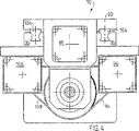
軸送り機構16が、固定取付け板90に固定的に取り付けられた、静止した軸送りモーター88を含んでいる。モーター88がねじ切りされたアウトプット・シャフト92を回転していて、アウトプット・シャフトは内面にねじ切りされたボールベアリングスクリュー94に係合され、連結され、そしてボールベアリングスクリューを動かす。ボールベアリングスクリュー94が、ブラケット36のアーム96に固定的に取り付けられていて、ブラケットアーム96は、軸48を取り囲んでいる環状ケーシング100にねじ98により、締めつけられている。軸受け102がケーシング100と軸48とを相互に連結していて、軸48がケーシング100に対して回転しないようにしている。一対の摺動ボックス104(図4)が取付け板90とブラケット36とを相互に連結していて、それらの間での相対的な摺動移動を可能にしている。
【0027】
偏心回転機構18が、軸48に係合する偏心回転ベルト108を駆動する、偏心回転モーター106を含んでいる。ベルト108が、軸48を主軸54の周囲で回転し、それにより、半径方向オフセット機構により作り出される主軸54からの工具軸26のオフセットがあるため、切削用工具24を主軸54の周囲で連動して偏心回転させる。
【0028】
運転にあたって、スピンドルモーター12が導管28を介して動力を受け取り、工具ホルダー22を回転し、切削用工具24を連動して回転する。軸送り機構16の軸送りモーター88がアウトプット・シャフト92を回転し、ボールベアリングスクリュー94を上下移動し、その上下移動はアウトプット・シャフト92の回転方向に依存している。ボールベアリングスクリュー94が、ブラケットアーム96およびブラケット台36を介して、スピンドルモーター12と、半径方向オフセット機構14と、偏心回転機構18とに、それぞれ結合されているモーター86および106に沿って、固定的に結合されている。このように、ボールベアリング94の軸方向の移動は、連動した軸方向の移動を、軸送り機構16を除いて、主軸ユニット10のほぼすべてにおいて引き起こしている。軸方向に対し静止している軸送り機構16の部品は、軸送りモーター88と、アウトプット・シャフト92と、取付け板90とを含んでいる。軸送り機構18の前述した運転により、回転している切削用工具24が、製作物に穴を機械加工するために、製作物(図示されていない)に前進されてもよい。
【0029】
図5に示めされるように、半径方向オフセット機構14は、切削用工具24により規定される工具軸26と、軸48および半径方向オフセットニードル52により規定される主軸48との間に半径方向オフセットを引き起こすために、運転されてもよい。半径方向オフセットモーター86が半径方向オフセットベルト84を駆動し、引き続いて、ディスク型スクリュー80を回転する。スクリュー80の中心穴82の中に螺合的に受入れられたスリーブ78が、スクリュー80の回転方向に従い、スクリュー80に対し軸方向に上下移動する。スリーブ78が半径方向オフセットニードル52に嵌合されていて、ニードル52はスリーブ78のどのような軸方向移動にも追従する。しかしながら、ニードル52はスリーブ78の中で回転可能である。スクリュー80が回転すると、スリーブ78は軸方向に移動する。続いて、スリーブ78がこの移動をニードル52に転じる。ニードル52は、このようにして偏心回転に沿った回転に対しては自由である。装置は、また機械加工中におけるオフセットの変更も可能で、円錐状の穴または複雑な形状の軸対称穴を機械加工するのに役に立つ。
【0030】
摺動ブロック40は、半径方向オフセットニードル52の軸方向移動に対応して半径方向に移動する。ばね66が、摺動ブロック40のテーパー状内部58の面60をニードル52の円錐状縁56に対して付勢している。図5に示めされるように、円錐状縁56と面60との一致した角度のために、お互いが物理的な境界面となり、ニードル52のスピンドルモーター12から遠ざかる移動は、摺動ブロック40の取付け板90に向けて摺動移動となる。摺動ブロック40は、軸48の回転に追従可能であると同時に、軸48に対し摺動する。摺動ブロック40は、摺動すると、環状アタッチメント30およびスピンドルモーター本体を摺動ブロックに沿って押す。このように、切削用工具24の工具軸26は、主軸54から引き離なされるか、またはオフセットされる。
【0031】
半径方向オフセットニードル52が図2に示めされる位置に向かって進むと、工具軸26と主軸54とが一致し、円錐状縁56が360度全周にわたってテーパー状内部58の面60と物理的な境界面となる。もし、円錐状縁56がこの位置にすばやく前進するなら、縁56がテーパー状内部58に押し込まれ動かなくなり、“クランピング(clamping)”と見なされる。縁56の先端部57がオリフィス61に近づくと、軸方向の力は、もし装置に弾力性がないと、わずかな軸方向変位に対し劇的に増大する。そのような弾力性はワッシャー型ばね89によりもたらされる。先端部57がオリフィス61に近づくと、ワッシャー型ばね89はブッシュ87の頂部に接触し、かつ圧縮し始める。ばね89は収縮し始めると、ニードル52と先端部57とのオリフィス61に向けてのさらなる前進に対抗する。このようにしてクランピングの危険はほぼなくなる。
【0032】
偏心回転機構18の運転は、切削用工具24の主軸54を囲む円を描く、振動および旋回を引き起こし、同時に工具24は自分自身の軸26の周囲を回転する。円振動の半径は、工具軸26と主軸54との間の半径方向オフセットにほぼ等しい。摺動ブロック40が軸48にそって摺動すると、ばね66はまた回転する。ばね66の回転位置が変化すると、摺動ブロック40のオフセット方向と、切削用工具24の主軸54からのオフセットが連動して変化を受ける。切削用工具24は、主軸54からオフセットすると、ばね66が主軸54の周囲を回転するごとに、主軸54の周囲を完全に一回転する。
【0033】
止めピン32が、アタッチメント30とスピンドルモーター本体20とを固定していて、スピンドルモーター本体20は常に同一で所定の方向に面していて、工具軸26の周りで回転できない。しかしながら軸受44は、アタッチメント30が回転できなくても、摺動ブロック40が工具軸26の周囲を自由に回転することを可能にしている。摺動ブロック40における、半径方向オフセットおよび回転は、アタッチメント30が主軸54を囲む円形通路における振動を引き起こす。止めピン32が、軸26および54に直交するどのような方向においても、溝穴34の中で必要に応じ摺動し、アタッチメント30の振動に対し追従する。止めピン32が、常に溝穴34の中で同一の方向を指していて、すなわち、常に図示されるような同一の方向を指していて、スピンドルモーター本体20の方向を固定している。
【0034】
主軸ユニット10を使用して、切削用工具24が同時に、軸方向に送られ、自分自身の軸26の周囲を回転し、さらに切削用工具24の直径より大きな直径を有する穴あけ加工のために、主軸54の周囲を偏心的に振動してもよい。付け加えて、機械加工工程中に切削用工具24の半径方向オフセットを調節するための半径方向オフセット機構14を使用することにより、円錐状の穴、または軸対称の複雑な形状をした他の型式の穴を加工することが可能となる。
【0035】
ニードル縁面56と摺動ブロック40のテーパー状内部58との境界接触面は円錐形状を示めしている。しかしながら、境界接触面が円錐状以外の形状であってもよいことは理解される。ニードル縁面と摺動ブロックの内部面との、一つまたは両方が、わん曲形状、すなわち軸方向位置における函数としての、直線状ではない形状か、または放物線状の形状を有することも可能である。そのような直線状ではないニードル縁面、または直線状ではない内部面において、ニードル縁面は以下の特別な場合をのぞいて、ニードル縁面の軸方向長さ全体にわたっては、摺動ブロックの内部面と接触していない。以下の特別な場合とは、ニードル縁面と摺動ブロックの内部とが、同一または相補的な形状をしていて、さらにニードルが摺動ブロックの中に完全にそう入されている場合のことである。むしろニードルは、ニードル縁の軸方向長さに沿ったどこか一点で、摺動ブロックの内部面と接触していて、その一点はニードルの先端部からの位置函数である。わん曲した摺動ブロックの内部が、わん曲したニードル縁より十分に大きいことは可能である。
【0036】
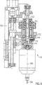
もう一つの実施の形態におけるスピンドルユニットが図6に示めされている。この実施の形態は、図7の拡大図に示めされる半径方向のオフセット機構をのぞいて、図1−5とほぼ同一のものである。シャフト112が、両方向矢印76で示めされる軸送り方向の方向であって、シャフトから半径方向に伸長しているピン116を持つ端部114を有している。シャフト112の端部114が、スリーブ118に嵌合していて、そのスリーブはピン116を係合する傾斜溝穴120を有している。スリーブ118が摺動ブロック122の中にしっかりと保持されていて、スリーブ118は摺動ブロック124の内面124に接触し境界面となっている。軸112の軸送り方向における移動は、図8に示めされるように、ピン116が傾斜溝穴120に沿って移動する結果を招く。というのは、スリーブ118が摺動ブロック122に対し軸方向に固定されているからである。ピン116の上向きの移動は、スリーブ118を移動し、続いて摺動ブロック124を取付け板126から引き離し、それにより、切削用工具128およびその軸130を主軸132から半径方向に移動する。スリーブ118と、ピン116と、傾斜溝穴120とは、摺動ブロック122の周囲を回転していて、オフセットの方向を主軸132の周囲に回転させ、それにより切削用工具128を主軸132の周囲で旋回する。
【0037】
同類でない材料から構成された構造物に、前述した装置を用いて、穴あけ機械加工する際、異なる材料において、直径のわずかな違いが現われるかも知れない。このことは、積み重なった材料における異なる材料の異なる機械的性質が、異なる切削力と異なる工具のたわみを招くことによるものである。積み重なった材料の切削用工具の出口面において、ばりまたは他の損傷が発生するかも知れない。
【0038】
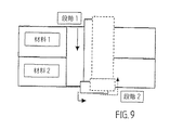
そのような直径の差および/またはばり/損傷は、図9に示めす以下の二つの方法により取り除いてもよい。一つの方法は、偏心オフセット有りまたは無しの初期穴あけ機械加工(段階1)に引き続き第二機械加工段階を実施することである。もう一つの方法は、工具を穴の中心軸を囲んで、自分自身の軸の周囲に回転すると同時に、工具を軸方向に送ることである。第二機械加工段階(段階2)は、積み重なった材料における、切削用工具の入口面からか、または切削用工具の出口面からのどちらから再開してもよい。
【0039】
同一の段階が、最初の穴の表面仕上に、第二段階における機械加工用データ(スピンドル速度および送り速度)を変更することにより、使用されてもよい。
【0040】
装置はまた、相対的に小さな直径の工具を使用して、数回の前述した段階により、比較的大きな穴あけ機械加工をするために使用されてもよい。パイロット・ホールの機械加工後、パイロット・ホールを拡大すべく、オフセットが増加され、前述の機械加工段階が行なわれてもよい。この段階を繰り返すことにより、大口径の穴が、機械の支持台の剛性の必要もなく、かつ切削力を上げることもなく機械加工することができる。
【0041】
本発明は好適な設計において説明されたけれど、本発明はこの開示の精神と範囲において、さらに修正されてもよい。これらの実施にあたっては、それ故本発明に共通する原理を使用した本発明のどのような変更と、使用と、適用とをも保護しようとするものである。さらにこれらの実施にあたっては、本発明の開示内容が、本発明に関係し、かつ前述の特許請求の範囲内にかかわる、従来技術において公知であり慣習であることから逸脱するのを保護しようとするものである。
【図面の簡単な説明】
【図1】 図1は、本発明の一つの実施の形態におけるスピンドルユニットの部分断面正面図である。
【図2】 図2は、図1における主軸ユニットの部分断面側面図であって、工具軸と主軸とが一致している。
【図3】 図3は、図1における主軸ユニットの半径方向オフセット機構の拡大部分側面図であって、工具軸と主軸とが一致している。
【図4】 図4は、図1における主軸ユニットの平面図である。
【図5】 図5は、図1における主軸ユニットの部分断面側面図であって、工具軸が主軸からオフセットしている。
【図6】 図6は、もう一つの実施の形態における主軸ユニットの部分断面側面図であって、工具軸と主軸とが一致している。
【図7】 図7は、図6における主軸ユニットの半径方向オフセット機構の拡大部分側面図であって、工具軸と主軸とが一致している。
【図8】 図8は、図6における主軸ユニットの部分断面図であって、工具軸が主軸からオフセットしている。
【図9】 図9は、二つの異なる材料から作られる製作物の断面であって、パイロットホールを加工する初期機械加工段階(段階1)の後における穴あけ拡大工程を示めしている。[0001]
Background of the Invention
1. TECHNICAL FIELD OF THE INVENTION
The present invention relates to a method and spindle unit for machining holes or recesses in a workpiece comprising a flat or curved sheet of fiber reinforced composite material, metal, or combinations thereof.
[0002]
2. Explanation of related technology
Structures in outer space and other applications are often made of thin bent shells of different materials such as aluminum, titanium, stainless steel, and fiber reinforced composites. In structural applications, different components are often engaged using bolted joints. Bolt holes for outer space structures are typically 4-20 mm in diameter, and high quality is required to ensure the integrity of the structure.
[0003]
The requirements for holes are related to dimensions and damage. Dimensional requirements include, for example, the diameter of the cylindrical hole, the height of the cylindrical portion of the hole, the diameter and angle of the countersink, the roughness, and the alignment in the nominal direction of the surface. Damage requirements include, among other things, acceptable burr height, surface finish, and acceptable delamination in fiber reinforced composites.
[0004]
The problem is particularly encountered when drilling fiber reinforced materials. Polymer composites have been generally known since the 1950s. These materials consist of coated and bonded polymers and are quoted as matrices with either thermoplastic or thermoset plastics, usually fibers (glass or carbon, or amide fibers). They may be regarded as reinforcing materials. The fibers may be continuous and oriented in a particular direction, or may be relatively short and arranged irregularly in a matrix.
Composite materials having fibers that are continuous and oriented in a direction are products that have mechanical properties superior to conventional polymer and metal materials, especially with respect to weight reinforcement and stiffness. Composite materials having short fibers have found applications where performance is not required. One factor that hinders the widespread use of composite materials is that there is no effective method of cutting machining. The physical and chemical properties of the composite means that the known machining methods are generally not successful.
[0005]
Composite products often contain holes for a variety of purposes. These holes may be needed, for example, to allow laying or assembling or inspecting a service line. Bolt holes are an important class of holes. Structures in conventional applications are often assembled from components that are joined together to make the final product. The purpose of the connection is to transfer the load from one structural element to the other. One common type of connection is a bolted joint, where the load is transmitted by a shear or tensile load within the bolt. The strength of bolted joints is significantly affected by hole quality and accuracy. The description will be given in particular to three problem areas when drilling into polymer-based fiber reinforced composites.
[0006]
1. Low strength between thin layers. When machining thin layer composites, there is a risk of separation (delamination) due to the low strength of the layers between the thin layers. Extensive delamination damage is fatal to thin layer strength.
2. Low heat resistance and low cooling resistance of thermoplastics. The heat generated during machining softens the matrix and blocks the tool, making machining impossible to continue. In order to achieve good quality of the hole, the edge of the tool / hole must be cooled effectively and the material removed by cutting (chips, debris, grinding debris) must be continuously removed from the hole .
3. High wear resistance in fibers. Cutting machining of fiber composite materials results in severe wear on the tool due to the good wear resistance properties of the fiber material. This is costly due to wear when machining holes with high accuracy.
[0007]
The methods used for drilling thin layer composites are traditional drilling, drilling, milling, sawing and grinding. As they are currently applied, the problems associated with these drilling methods are as follows, which are not sufficiently effective for various reasons from a technical / economic point of view: .
[0008]
The high cost due to wear is a general problem associated with cutting that requires high precision. When drilling or drilling, great care must be taken to ensure that delamination damage is avoided on both the entry and exit sides of the tool. Special tools are required to achieve the required hole quality and special machining methods must be developed. In order to avoid extensive delamination on the exit side of the thin layer tool, a partial lateral pressure must be applied around the edge of the hole. Another method of preventing the exit side of the tool disclosed so far from damage is to provide an additional protective layer on the thin layer.
[0009]
Saw machining is clearly an unsuitable method for drilling with high precision requirements. At the time of drilling by grinding, a cylindrical annular body is used, and a wear-resistant surface layer is applied to the end portion for machining. The hole is first processed by rotating the grinding body and simultaneously grinding the surface of the material orthogonally.
[0010]
From this point of view, the following has been pointed out, and in the drilling machining method, the body that is rotationally driven around the rotation axis also makes orbital movements (that is, the rotation axis faces the edge of the hole). It is well known that they are arranged so that they can move relative to each other. Swedish Patent No. 173899 (SE173899) has a tool transporter that rotates eccentrically around a main shaft, and the distance between the tool transporter and the main shaft is determined by a guide device. Rotates around the main shaft together with the conveyor. The guide device that rotates together with the conveyor is arranged perpendicular to the main shaft and is a cam that can rotate around the tool holder, and the tool holder is directly aged to the guiding contour of the cam. . The advantage of the present invention is, among other things, that there is no free play as a guide device and space is saved. However, the offset between the rotating shaft and the eccentric rotating shaft of the tool holder is fixed and determined by the size of the cam gear. Thus, the offset cannot be easily adjusted without replacing the cam gear inside the head. Swedish Patent No. 382506 (SE382506) discloses a rotationally driven and directly connected cutting tool for drilling into a stationary product, where the product hole includes a conical chamfered chamfer. You may have.
[0011]
US Pat. No. 5,641,252 (Eriksson et al.) Discloses a method of machining holes in fiber reinforced composites, which is a very advanced stage of technology. The central axis of the hole passes through a predetermined point on the surface of the product and is oriented in a direction relative to the longitudinal direction of the fiber in the immediate vicinity of that point. The material is machined both axially and radially simultaneously by causing the tool to move and rotate axially, not only around its own axis, but also eccentrically around the central axis. This method makes it possible to machine holes without causing delamination in the composite material.
[0012]
Space and related structures are generally made by stacking different materials together. A special problem arises when drilling simultaneously into a structure containing several layers of different materials (laminate materials). Such problems include flash between layers close to the holes and damage to the bonding material between the layers (liquid shims). Drilling using conventional techniques generates heat that quickly wears the tool. This problem is particularly serious when drilling titanium.
[0013]
It is known to use a robot controller that attaches a conventional spindle with a robot arm and commands movement to a cutting tool. The problem is that the accuracy and quality of the drilling results is limited by the robot's mechanism and the controller attached to the robot, which is designed to move and position the heavy robot arm. Has been. Thus, the accuracy and performance of the robot mechanism and control device is not sufficient to machine high precision fastener holes at high speeds, for example, with the required movement.
[0014]
Summary of the present invention
The present invention eliminates the disadvantages and limitations associated with previously disclosed methods and allows for rational and cost-effective drilling without strength-reducing damage and flashing, thereby improving quality. Guarantees a good hole. The present invention provides a spindle unit for drilling a workpiece having a cutting tool having a first rotating shaft, the cutting tool also being adjustable using a mechanical drive element It is possible to move around the second eccentric rotation shaft. The spindle unit may be attached to a robotic arm that is used to position and orient the end effector and the precise machining is controlled by the spindle unit.
[0015]
In one form of the invention, a product drilling machine includes a spindle motor that is rotatable about a spindle. The spindle motor includes a tool holder having a tool axis substantially parallel to the main axis. The tool holder is rotatable around the tool axis. The axial actuator is shaped to move the spindle motor in an axial feed direction substantially parallel to each of the main axis and the tool axis. The radial actuator is shaped to adjust the radial distance between the main axis and the tool axis.
[0016]
Eccentric rotational movement is achieved by exact rotational movement, i.e. a constant or continuously changing distance between the central axis and the rotational axis of the tool.
[0017]
The device generally has many advantages over known machines:
1. The apparatus makes it possible to easily adjust the radial offset between the rotary axis of the cutting tool and the eccentric rotary axis without having to replace any parts.
2. The apparatus enables high-precision and high-quality drilling production than can be achieved by using a robot arm control device.
3. The method enables drilling production with tight tolerances. The dimensional accuracy of drilling is almost determined by the positioning accuracy of the tool with respect to the central axis. The requirements for tool geometry are not particularly demanding, while all individual tools are easily calibrated before use.
[0018]
By referring to the following description of the embodiments of the present invention in conjunction with the accompanying drawings, the above and other aspects and advantages of the present invention and methods for realizing them will become clearer, and the present invention will be more clearly understood. Understood.
In the drawings, the same reference numerals denote the same parts. The description here is given by way of example in a preferred embodiment of the present invention, but this description does not limit any scope in the present invention.
[0019]
Detailed Description of the Invention
In FIG. 1, the
[0020]
The
[0021]
The top of the
[0022]
The radial offset
[0023]
The
[0024]
The radial offset
[0025]
An upper portion of the
[0026]
The shaft feed mechanism 16 includes a stationary
[0027]
The
[0028]
In operation, the
[0029]
As shown in FIG. 5, the radial offset
[0030]
The sliding
[0031]
As the radial offset
[0032]
The operation of the
[0033]
A
[0034]
Using the
[0035]
The boundary contact surface between the
[0036]
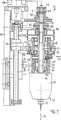
A spindle unit in another embodiment is shown in FIG. This embodiment is substantially the same as FIG. 1-5 except for the radial offset mechanism shown in the enlarged view of FIG. The
[0037]
Slight differences in diameters may appear in different materials when drilling into structures constructed from dissimilar materials using the previously described apparatus. This is due to the different mechanical properties of the different materials in the stacked material leading to different cutting forces and different tool deflections. Flash or other damage may occur at the exit surface of the stacked material cutting tool.
[0038]
Such diameter differences and / or flash / damage may be removed by the following two methods shown in FIG. One method is to perform an initial drilling machining (stage 1) with or without eccentric offset followed by a second machining stage. Another method is to feed the tool axially while simultaneously rotating the tool around its own axis around its own axis. The second machining stage (stage 2) may resume either from the cutting tool entry surface or from the cutting tool exit face in the stacked material.
[0039]
The same stage may be used for the surface finish of the first hole by changing the machining data (spindle speed and feed speed) in the second stage.
[0040]
The apparatus may also be used for relatively large drilling machining, using a relatively small diameter tool, in several steps as described above. After machining the pilot hole, the offset may be increased and the machining steps described above may be performed to enlarge the pilot hole. By repeating this step, a large-diameter hole can be machined without the need for rigidity of the machine support and without increasing the cutting force.
[0041]
While this invention has been described in a preferred design, the present invention may be further modified within the spirit and scope of this disclosure. These implementations are therefore intended to protect any modification, use, and application of the present invention which employs principles common to the present invention. Furthermore, in carrying out these, the disclosure of the present invention seeks to protect the departure from what is known and customary in the prior art which is related to the present invention and which is within the scope of the above claims. Is.
[Brief description of the drawings]
FIG. 1 is a partial sectional front view of a spindle unit according to an embodiment of the present invention.
FIG. 2 is a partial cross-sectional side view of the main spindle unit in FIG. 1, in which the tool axis and the main axis coincide.
FIG. 3 is an enlarged partial side view of the radial offset mechanism of the main spindle unit in FIG. 1, in which the tool axis and the main axis coincide with each other.
4 is a plan view of the spindle unit in FIG. 1. FIG.
FIG. 5 is a partial cross-sectional side view of the spindle unit in FIG. 1, in which the tool axis is offset from the spindle.
FIG. 6 is a partial cross-sectional side view of a main spindle unit according to another embodiment, in which a tool axis and a main axis coincide with each other.
FIG. 7 is an enlarged partial side view of the radial offset mechanism of the main spindle unit in FIG. 6, in which the tool axis and the main axis coincide with each other.
FIG. 8 is a partial cross-sectional view of the spindle unit in FIG. 6, in which the tool axis is offset from the spindle.
FIG. 9 is a cross-section of a workpiece made from two different materials, showing the drilling enlargement process after the initial machining stage (stage 1) of machining the pilot hole.
Claims (6)
前記切削用工具(24)を支持する工具ホルダー(22)を有するスピンドルモーター(12)であり、該穴を機械加工している間、該切削用工具(24)をその工具軸の周囲で回転させるスピンドルモーター(12)を含んだ第一アクチュエーターと;
該切削用工具(24)を該工具軸(26)にほぼ平行な軸送り方向に移動するべく形造られていて、該第一アクチュエーター(12)と同時に運転可能である第二アクチュエーター(16)と;
該穴あけ加工するために、該切削用工具を該切削用工具の該工具軸にほぼ平行な主軸(54)の周囲で偏心回転するべく形造られていて、該第一アクチュエーター(12)および該第二アクチュエーター(16)と同時に運転可能である第三アクチュエーター(18)と、
該切削用工具の該工具軸(26)における、該主軸(54)からの半径方向距離を調節するべく形造られた半径方向オフセット機構(14)と;
を具備する穴あけ機械加工装置において、
前記半径方向オフセット機構(14)は、工具ホルダー(22)と結合された摺動ブロック(40)に、主軸(54)と同軸の軸方向変位可能軸(52)により、駆動のため接続された第四アクチュエーター(86)を含んでおり、その結果、前記軸送り方向への前記軸方向変位可能軸(52)の移動が、前記摺動ブロック(40)のすなわち工具ホルダー(22)の半径方向移動をもたらし、
該摺動ブロック(40)が、傾斜内面(60)を含んでいて、回転自在な前記軸方向変位可能軸(52)が、円錐状縁(56)を有していて、該円錐状縁は該摺動ブロック(40)の該傾斜内面と境界面となっていて、前記軸方向変位可能軸(52)の該軸送り方向の移動が連動した該摺動ブロックの半径方向の移動をもたらし、
該円錐状縁(56)が、外径を有する先端部(57)を含んでいて、該摺動ブロック(40)の該傾斜内面(60)は内径を有するオリフィス(61)を形成しており、該オリフィス(61)の該内径が、該先端部(57)の該外径にほぼ等しいところの、穴あけ機械加工装置。To drilling machining to productions, a device that uses a cutting tool (2 4) having a first width and a tool axis and (2 6), than the first width bore of the cutting tool In an apparatus having a large second width, the drilling machine is
Wherein a cutting tool (2 4) spindle motor (12) having a tool holder (22) for supporting a periphery of the tool axis between, the cutting tool (2 4) that machine the bore A first actuator including a spindle motor (12) for rotation with;
The cutting tool (2 4) have been fashioned in order to move substantially parallel to the axial feed direction to said tool shaft (2 6), said first actuator (12) at the same time as the second actuator is operable ( 16) and;
For the drilling, the cutting tool is shaped for eccentric rotation about a main axis ( 54 ) substantially parallel to the tool axis of the cutting tool, the first actuator (12) and A third actuator (18) operable simultaneously with the second actuator (16);
The said tool axis of the cutting tool in the (2 6), the main shaft (4) radially offset mechanism a radial distance were fashioned so as to adjust from (1 4);
In the drilling machining apparatus comprising
The radial offset mechanism (14 ) is driven by a slide block (40 ) coupled to a tool holder (22) by an axially displaceable shaft (52 ) coaxial with the main shaft (54 ) . A fourth actuator (86) connected for this purpose, so that the movement of the axially displaceable shaft (52 ) in the axial feed direction is a tool holder of the sliding block (40 ) also cod radial movement of (22),
The sliding block (40) includes an inclined inner surface (60), the rotatable axially displaceable shaft (52) has a conical edge (56), the conical edge being The sliding block (40) is a boundary surface with the inclined inner surface, and the movement of the axially displaceable shaft (52) in the axial feed direction causes the radial movement of the sliding block,
The conical edge (56) includes a tip (57) having an outer diameter, and the inclined inner surface (60) of the sliding block (40) forms an orifice (61) having an inner diameter. A drilling machine where the inner diameter of the orifice (61) is approximately equal to the outer diameter of the tip (57) .
該半径方向オフセットベルト(84)が、内面にねじ切りされたディスク型スクリュー(80)を、前記軸方向変位可能軸(52)に接続されているねじ切りされたスリーブ(78)の周囲に回転することにより該ねじ切りされたスリーブを該軸送り方向に移動して、前記工具ホルダー(22)の半径方向移動をもたらすところの、請求項1から3のいずれか1項に記載の穴あけ機械加工装置。The radial offset mechanism (1 4), include a radial offset motor driving a radial offset belt (84) (86),
The radial offset belt (84) rotates the disk-type screw that is threaded on the inner surface (80), around the axis displaceable axis (5 2) are connected threaded sleeve (78) 4. The drilling machine according to any one of claims 1 to 3 , wherein the threaded sleeve is moved in the axial feed direction to cause a radial movement of the tool holder (22).
Applications Claiming Priority (3)
| Application Number | Priority Date | Filing Date | Title |
|---|---|---|---|
| US09/092,467 | 1998-06-05 | ||
| US09/092,467 US5971678A (en) | 1998-06-05 | 1998-06-05 | Spindle unit |
| PCT/SE1999/000955 WO1999062661A1 (en) | 1998-06-05 | 1999-06-03 | Spindle unit for producing a hole in a work piece of fiber-reinforced composite material |
Publications (2)
| Publication Number | Publication Date |
|---|---|
| JP2002516761A JP2002516761A (en) | 2002-06-11 |
| JP4620249B2 true JP4620249B2 (en) | 2011-01-26 |
Family
ID=22233361
Family Applications (1)
| Application Number | Title | Priority Date | Filing Date |
|---|---|---|---|
| JP2000551910A Expired - Fee Related JP4620249B2 (en) | 1998-06-05 | 1999-06-03 | Spindle unit for drilling in the production of fiber reinforced composite materials |
Country Status (7)
| Country | Link |
|---|---|
| US (1) | US5971678A (en) |
| EP (1) | EP1102653B1 (en) |
| JP (1) | JP4620249B2 (en) |
| AU (1) | AU4810199A (en) |
| DE (1) | DE69919874T2 (en) |
| ES (1) | ES2226405T3 (en) |
| WO (1) | WO1999062661A1 (en) |
Families Citing this family (31)
| Publication number | Priority date | Publication date | Assignee | Title |
|---|---|---|---|---|
| DE19830903B4 (en) * | 1998-07-10 | 2006-07-13 | Gebr. Heller Maschinenfabrik Gmbh | Device and method for machining holes in a workpiece using such a device |
| US6382890B1 (en) * | 1999-09-01 | 2002-05-07 | Novator Ab | Hand tool apparatus for orbital drilling |
| US6719505B2 (en) | 1999-09-01 | 2004-04-13 | Novator Ab | Orbital hand tool apparatus for drilling |
| ATE432140T1 (en) * | 2001-07-11 | 2009-06-15 | Novator Ab | DEVICE FOR CREATING A CONICAL OR SHAPED HOLE IN A WORKPIECE |
| EP1417067B1 (en) * | 2001-07-20 | 2010-11-24 | Novator AB | Numerically controlled orbital machining apparatus |
| DE10255986A1 (en) * | 2002-11-30 | 2004-06-09 | Andreas Stihl Ag & Co. Kg | Device for forming control windows in a cylinder wall |
| JP4500305B2 (en) * | 2003-06-02 | 2010-07-14 | ノバトール アーベー | Depth measuring method and depth measuring device for hole formed in composite material processed body by orbital cutting tool |
| DE602004025109D1 (en) * | 2003-06-26 | 2010-03-04 | Novator Ab | DEVICE FOR REVOLUTIONARY MACHINING WITH DRIVING ELEMENT WITH DRIVE PINS |
| US20060269369A1 (en) * | 2005-05-24 | 2006-11-30 | The Boeing Company | Portable electro-pneumatic drill apparatus |
| US7627940B2 (en) * | 2005-07-13 | 2009-12-08 | The Boeing Company | Orbital hole match drilling |
| JP2007075939A (en) * | 2005-09-13 | 2007-03-29 | Kyokuei Kenma Co Ltd | Drilling machine |
| GB0601811D0 (en) * | 2006-01-30 | 2006-03-08 | Nothelfer Uk Ltd | Drilling and riveting |
| JP4897311B2 (en) * | 2006-02-28 | 2012-03-14 | オークマ株式会社 | Dust-proof mechanism of main spindle |
| ES2622144T3 (en) * | 2007-05-18 | 2017-07-05 | Hukuzo Yagishita | Drilling device and method to produce a perforated object |
| ITMI20072062A1 (en) * | 2007-10-25 | 2009-04-26 | Campagnolo Srl | BICYCLE CHANGE |
| US8256092B1 (en) | 2008-01-30 | 2012-09-04 | Makino Inc. | Method for helical boring |
| DE102008031487A1 (en) | 2008-07-03 | 2010-01-07 | Ex-Cell-O Gmbh | Processing plant for workpieces |
| JP5278758B2 (en) * | 2009-05-15 | 2013-09-04 | 本田技研工業株式会社 | Cam drive device and processing method |
| DE102010013480A1 (en) * | 2009-10-02 | 2011-04-07 | Ferroll Gmbh | Cutting tool, in particular peeling tool, boring head, solid boring head or boring head, as well as a cutting machine and method |
| EP3038792A4 (en) | 2013-08-26 | 2017-06-21 | Novator AB | Method, system, computer program and a computer program product for measuring objects |
| US9677608B2 (en) | 2013-11-13 | 2017-06-13 | Cnh Industrial America Llc | Agricultural rolling basket bearing assembly |
| CN106457498B (en) * | 2014-05-26 | 2019-04-23 | 诺瓦特公司 | Method, system and storage medium for workpiece machining |
| CN104669362A (en) * | 2015-02-11 | 2015-06-03 | 四川省青城机械有限公司 | Centrifugal feeder spindle system |
| CN104670853B (en) * | 2015-02-11 | 2016-08-17 | 四川省青城机械有限公司 | A kind of centrifugal feeder |
| US9770769B2 (en) * | 2016-01-22 | 2017-09-26 | The Boeing Company | Orbital drilling system and associated methods and apparatuses |
| US10138936B2 (en) | 2016-12-13 | 2018-11-27 | Cnh Industrial America Llc | Agricultural rolling basket bearing assembly |
| EP4140625A4 (en) * | 2020-04-20 | 2023-06-07 | Dalian University Of Technology | PORTABLE HELICAL MILLING UNIT AND ECCENTRICITY SETTING METHOD |
| CN112536618B (en) * | 2020-12-09 | 2025-01-07 | 成都齐平科技有限公司 | A tool radial adjustment mechanism |
| CN114871825A (en) * | 2022-06-21 | 2022-08-09 | 哈尔滨理工大学 | Adjusting device of eccentric sleeve type spiral hole making equipment |
| GB202215383D0 (en) * | 2022-10-18 | 2022-11-30 | Rolls Royce Plc | Needle apparatus |
| IT202300023589A1 (en) * | 2023-11-09 | 2025-05-09 | Walter Tosto S P A | ORBITAL AXIAL GRINDER FOR NOZZLES |
Family Cites Families (17)
| Publication number | Priority date | Publication date | Assignee | Title |
|---|---|---|---|---|
| SE173899C1 (en) * | ||||
| US2608807A (en) * | 1949-11-17 | 1952-09-02 | Onsrud Machine Works Inc | Precision hole grinder |
| DE2054165B2 (en) * | 1970-11-04 | 1979-11-08 | Cross Europa-Werk Gmbh, 7317 Wendlingen | Eccentric headstock |
| US4043700A (en) * | 1976-11-15 | 1977-08-23 | Toolmatic Corporation | X-Y control for radial arm and headstock of a radial drilling machine |
| US4569115A (en) * | 1983-09-06 | 1986-02-11 | Ikegai Tekko Kabushiki Kaisha | Method and apparatus for controlling the depth of cut in the radial direction of a rotary cutting tool in a machine tool |
| JPS62181303U (en) * | 1986-05-06 | 1987-11-17 | ||
| DE3631156C2 (en) * | 1986-09-12 | 1994-10-06 | Deckel Ag Friedrich | Radially adjustable tool |
| JPH0432163Y2 (en) * | 1986-11-12 | 1992-08-03 | ||
| JP2879151B2 (en) * | 1989-07-04 | 1999-04-05 | 富士精工株式会社 | Cutting equipment with adjustable blade position |
| JPH0373203A (en) * | 1989-08-11 | 1991-03-28 | Mitsui Seiki Kogyo Co Ltd | Method and device for machining inner groove by double eccentric shaft |
| IT1247783B (en) * | 1990-11-23 | 1994-12-30 | Vigel Spa | MACHINE TOOL WITH CHIP REMOVAL WITH SPINDLE HEAD WITH THREE DEGREES OF FREEDOM |
| DE4127745A1 (en) * | 1991-08-22 | 1993-02-25 | Fischer Artur Werke Gmbh | DEVICE FOR PRODUCING DRILL HOLES WITH UNDERCUT |
| JP3310014B2 (en) * | 1992-04-02 | 2002-07-29 | 黒田精工株式会社 | U-axis mechanism connecting device |
| JP3267619B2 (en) * | 1992-04-02 | 2002-03-18 | プリム・セルゲイ・フョードロヴィッチ | Spindle head of metal working machine tool |
| SE9300400L (en) * | 1993-02-05 | 1994-08-06 | Strukturteknologier I Stockhol | Machine tool for receiving a through opening in a fiber composite article |
| JPH0796410A (en) * | 1993-09-28 | 1995-04-11 | Hiramatsu Kiki Seisakusho:Kk | Speed-up device for face plate type boring machine |
| JPH10138013A (en) * | 1996-11-11 | 1998-05-26 | Mori Seiki Co Ltd | Machine tool radial cutting device |
-
1998
- 1998-06-05 US US09/092,467 patent/US5971678A/en not_active Expired - Lifetime
-
1999
- 1999-06-03 WO PCT/SE1999/000955 patent/WO1999062661A1/en not_active Ceased
- 1999-06-03 JP JP2000551910A patent/JP4620249B2/en not_active Expired - Fee Related
- 1999-06-03 ES ES99931658T patent/ES2226405T3/en not_active Expired - Lifetime
- 1999-06-03 DE DE69919874T patent/DE69919874T2/en not_active Expired - Lifetime
- 1999-06-03 EP EP99931658A patent/EP1102653B1/en not_active Expired - Lifetime
- 1999-06-03 AU AU48101/99A patent/AU4810199A/en not_active Abandoned
Also Published As
| Publication number | Publication date |
|---|---|
| EP1102653B1 (en) | 2004-09-01 |
| JP2002516761A (en) | 2002-06-11 |
| ES2226405T3 (en) | 2005-03-16 |
| DE69919874D1 (en) | 2004-10-07 |
| AU4810199A (en) | 1999-12-20 |
| EP1102653A1 (en) | 2001-05-30 |
| WO1999062661A1 (en) | 1999-12-09 |
| US5971678A (en) | 1999-10-26 |
| DE69919874T2 (en) | 2005-08-25 |
Similar Documents
| Publication | Publication Date | Title |
|---|---|---|
| JP4620249B2 (en) | Spindle unit for drilling in the production of fiber reinforced composite materials | |
| CN100341651C (en) | Orbital hand tool apparatus for drilling | |
| US6702531B2 (en) | Hand tool apparatus for orbital drilling | |
| US5207541A (en) | Scarfing apparatus | |
| WO1994017944A1 (en) | HAND TOOL FOR MAKING HOLES IN e.g. FIBRE-REINFORCED COMPOSITES, BY MEANS OF AN ORBITALLY MOVING CUTTER | |
| JP3915914B2 (en) | Method for providing a hole in a fiber reinforced composite product | |
| US8052030B2 (en) | Apparatus for friction stir welding using spindle-in-spindle | |
| CN102892538A (en) | Boring device | |
| US6773211B2 (en) | Orbital drilling cutting tool | |
| GB2125323A (en) | Device for honing workpieces | |
| US7547169B1 (en) | Drilling module with automatic tool changer | |
| US5203856A (en) | Tool for finishing and chamfering a hole | |
| JPH05253818A (en) | Drill grinding machine | |
| KR102659624B1 (en) | Complex Manufacturing Machine | |
| JP2002219602A (en) | Edge processing machine | |
| US20260115810A1 (en) | Machining Device | |
| CN119304730B (en) | PDC end face, chamfering grinding machine and machining method | |
| US20260115800A1 (en) | Tool Holding Device for a Turning Application and Lathe Comprising Such a Tool Holding Device | |
| JPH0627286Y2 (en) | Revolution radius adjusting device for revolution tool | |
| CN120920782A (en) | Drilling processing cutter | |
| JP2001047301A (en) | Cutting method for work material and lathe |
Legal Events
| Date | Code | Title | Description |
|---|---|---|---|
| A621 | Written request for application examination |
Free format text: JAPANESE INTERMEDIATE CODE: A621 Effective date: 20060308 |
|
| A131 | Notification of reasons for refusal |
Free format text: JAPANESE INTERMEDIATE CODE: A131 Effective date: 20090331 |
|
| A521 | Request for written amendment filed |
Free format text: JAPANESE INTERMEDIATE CODE: A523 Effective date: 20090626 |
|
| A02 | Decision of refusal |
Free format text: JAPANESE INTERMEDIATE CODE: A02 Effective date: 20100223 |
|
| A521 | Request for written amendment filed |
Free format text: JAPANESE INTERMEDIATE CODE: A523 Effective date: 20100622 |
|
| A521 | Request for written amendment filed |
Free format text: JAPANESE INTERMEDIATE CODE: A821 Effective date: 20100625 |
|
| A911 | Transfer to examiner for re-examination before appeal (zenchi) |
Free format text: JAPANESE INTERMEDIATE CODE: A911 Effective date: 20100716 |
|
| TRDD | Decision of grant or rejection written | ||
| A01 | Written decision to grant a patent or to grant a registration (utility model) |
Free format text: JAPANESE INTERMEDIATE CODE: A01 Effective date: 20100928 |
|
| A01 | Written decision to grant a patent or to grant a registration (utility model) |
Free format text: JAPANESE INTERMEDIATE CODE: A01 |
|
| A61 | First payment of annual fees (during grant procedure) |
Free format text: JAPANESE INTERMEDIATE CODE: A61 Effective date: 20101028 |
|
| FPAY | Renewal fee payment (event date is renewal date of database) |
Free format text: PAYMENT UNTIL: 20131105 Year of fee payment: 3 |
|
| R150 | Certificate of patent or registration of utility model |
Free format text: JAPANESE INTERMEDIATE CODE: R150 |
|
| R250 | Receipt of annual fees |
Free format text: JAPANESE INTERMEDIATE CODE: R250 |
|
| LAPS | Cancellation because of no payment of annual fees |