JP4619803B2 - Fluorescence tomographic image acquisition device - Google Patents
Fluorescence tomographic image acquisition device Download PDFInfo
- Publication number
- JP4619803B2 JP4619803B2 JP2005018347A JP2005018347A JP4619803B2 JP 4619803 B2 JP4619803 B2 JP 4619803B2 JP 2005018347 A JP2005018347 A JP 2005018347A JP 2005018347 A JP2005018347 A JP 2005018347A JP 4619803 B2 JP4619803 B2 JP 4619803B2
- Authority
- JP
- Japan
- Prior art keywords
- tomographic image
- light
- fluorescence
- ultrasonic
- test
- Prior art date
- Legal status (The legal status is an assumption and is not a legal conclusion. Google has not performed a legal analysis and makes no representation as to the accuracy of the status listed.)
- Expired - Fee Related
Links
Images


Classifications
-
- A—HUMAN NECESSITIES
- A61—MEDICAL OR VETERINARY SCIENCE; HYGIENE
- A61B—DIAGNOSIS; SURGERY; IDENTIFICATION
- A61B5/00—Measuring for diagnostic purposes; Identification of persons
- A61B5/0059—Measuring for diagnostic purposes; Identification of persons using light, e.g. diagnosis by transillumination, diascopy, fluorescence
- A61B5/0062—Arrangements for scanning
- A61B5/0066—Optical coherence imaging
-
- A—HUMAN NECESSITIES
- A61—MEDICAL OR VETERINARY SCIENCE; HYGIENE
- A61B—DIAGNOSIS; SURGERY; IDENTIFICATION
- A61B5/00—Measuring for diagnostic purposes; Identification of persons
- A61B5/0059—Measuring for diagnostic purposes; Identification of persons using light, e.g. diagnosis by transillumination, diascopy, fluorescence
- A61B5/0071—Measuring for diagnostic purposes; Identification of persons using light, e.g. diagnosis by transillumination, diascopy, fluorescence by measuring fluorescence emission
-
- A—HUMAN NECESSITIES
- A61—MEDICAL OR VETERINARY SCIENCE; HYGIENE
- A61B—DIAGNOSIS; SURGERY; IDENTIFICATION
- A61B5/00—Measuring for diagnostic purposes; Identification of persons
- A61B5/0059—Measuring for diagnostic purposes; Identification of persons using light, e.g. diagnosis by transillumination, diascopy, fluorescence
- A61B5/0073—Measuring for diagnostic purposes; Identification of persons using light, e.g. diagnosis by transillumination, diascopy, fluorescence by tomography, i.e. reconstruction of 3D images from 2D projections
-
- A—HUMAN NECESSITIES
- A61—MEDICAL OR VETERINARY SCIENCE; HYGIENE
- A61B—DIAGNOSIS; SURGERY; IDENTIFICATION
- A61B5/00—Measuring for diagnostic purposes; Identification of persons
- A61B5/0059—Measuring for diagnostic purposes; Identification of persons using light, e.g. diagnosis by transillumination, diascopy, fluorescence
- A61B5/0082—Measuring for diagnostic purposes; Identification of persons using light, e.g. diagnosis by transillumination, diascopy, fluorescence adapted for particular medical purposes
- A61B5/0084—Measuring for diagnostic purposes; Identification of persons using light, e.g. diagnosis by transillumination, diascopy, fluorescence adapted for particular medical purposes for introduction into the body, e.g. by catheters
-
- A—HUMAN NECESSITIES
- A61—MEDICAL OR VETERINARY SCIENCE; HYGIENE
- A61B—DIAGNOSIS; SURGERY; IDENTIFICATION
- A61B8/00—Diagnosis using ultrasonic, sonic or infrasonic waves
- A61B8/12—Diagnosis using ultrasonic, sonic or infrasonic waves in body cavities or body tracts, e.g. by using catheters
Description
本発明は、被検部へ励起光を照射し、被検部から発せられた蛍光を検出し、被検部の蛍光断層画像を取得する蛍光断層画像取得装置に関するものである。 The present invention relates to a fluorescence tomographic image acquisition apparatus that irradiates a test part with excitation light, detects fluorescence emitted from the test part, and acquires a fluorescent tomographic image of the test part.
近年、光を用いて断層画像を取得する光断層画像取得装置が医療診断の分野に使用されている。従来、共焦点光学系の光断層画像取得装置あるいは時間分解計測系の光断層画像取得装置などが実用化されている。 In recent years, optical tomographic image acquisition apparatuses that acquire tomographic images using light have been used in the field of medical diagnosis. Conventionally, an optical tomographic image acquisition apparatus of a confocal optical system or an optical tomographic image acquisition apparatus of a time-resolved measurement system has been put into practical use.
また、近年、OCT(Optical Coherence Tomography)装置の実用化もすすめられている。OCT装置は、SLD(Super Luminescent Diode)などから成る光源から出射された低コヒーレンス光を測定光と参照光に分割し、ピエゾ素子等により参照光または測定光の周波数を僅かにシフトさせ、測定光を被検部に入射させて被検部の所定の深度で反射した反射光と参照光とを干渉させ、その干渉光の光強度をヘテロダイン検波により測定し、断層情報を取得するものであり、参照光の光路上に配置した可動ミラーなどを微少移動させ、参照光の光路長を僅かに変化させることにより、参照光の光路長と測定光の光路長が一致した被検部の深度での情報を得ることができる。 In recent years, practical use of an OCT (Optical Coherence Tomography) apparatus has been promoted. The OCT apparatus divides low-coherence light emitted from a light source such as an SLD (Super Luminescent Diode) into measurement light and reference light, and slightly shifts the frequency of the reference light or measurement light by a piezo element or the like. Is incident on the test portion, the reflected light reflected at a predetermined depth of the test portion and the reference light are caused to interfere, the light intensity of the interference light is measured by heterodyne detection, and tomographic information is obtained. By moving the movable mirror, etc., placed on the optical path of the reference light slightly, and slightly changing the optical path length of the reference light, the optical path length of the reference light and the optical path length of the measurement light coincide with each other at the depth of the test part. Information can be obtained.
さらに、超音波と光を同時に被検部へ照射し、超音波の作用を受けた被検部で反射した超音波変調反射光に基づいて、被検部の超音波変調光断層画像を取得する超音波変調光断層画像取得装置の開発も近年進められている(非特許文献1参照)。 Furthermore, an ultrasonic wave and light are simultaneously irradiated onto the test part, and an ultrasonically modulated optical tomographic image of the test part is acquired based on the ultrasonically modulated reflected light reflected by the test part that has been affected by the ultrasonic wave. Development of an ultrasonic modulation optical tomographic image acquisition apparatus has also been promoted in recent years (see Non-Patent Document 1).
また、被検部へ励起光を照射し、発せられる蛍光を検出して蛍光断層画像を取得する共焦点光学系の蛍光断層画像取得装置が、共焦点顕微鏡として実用化されている。また、時間分解計測系の蛍光断層画像取得装置も知られている(特許文献1参照)。
しかしながら、共焦点光学系の蛍光断層画像取得装置は、高解像度で光断層画像を取得することができるが、被検部の表面から0.5mm以上の深さの蛍光断層画像の取得が困難であるという問題がある。また時間分解計測系の蛍光断層画像取得装置は、表面から数cmmまでの深さの蛍光断層画像を取得できるが、解像度の上限が1mm程度であり、十分な解像度が得られないという問題がある。特に、医療分野においては、病変組織の深達度などを診断するために、深さ数mmまで蛍光断層画像を、高解像度で取得できる蛍光断層画像取得装置の実現が強く望まれている。 However, the confocal optical fluorescence tomographic image acquisition apparatus can acquire an optical tomographic image with high resolution, but it is difficult to acquire a fluorescent tomographic image having a depth of 0.5 mm or more from the surface of the test part. There is a problem that there is. Moreover, the fluorescence tomographic image acquisition apparatus of the time-resolved measurement system can acquire a fluorescent tomographic image having a depth of several cmm from the surface, but there is a problem that the upper limit of the resolution is about 1 mm and sufficient resolution cannot be obtained. . In particular, in the medical field, in order to diagnose the depth of a diseased tissue, it is strongly desired to realize a fluorescent tomographic image acquisition apparatus that can acquire a fluorescent tomographic image with a high resolution up to a depth of several millimeters.
本発明は、上記問題に鑑み、深さ数mmまで蛍光断層画像を、高解像度で取得できる蛍光断層画像取得装置を提供することを目的とするものである。 In view of the above problems, an object of the present invention is to provide a fluorescent tomographic image acquisition apparatus that can acquire a fluorescent tomographic image with a high resolution up to a depth of several millimeters.
本発明による蛍光断層画像取得装置は、被検部へ第1の超音波と励起光を同時に照射し、前記第1の超音波の作用を受けた前記被検部から発せられる超音波変調蛍光に基づいて、前記被検部の超音波変調蛍光断層画像を取得する蛍光断層画像取得手段を備えたことを特徴とするものである。 The fluorescence tomographic image acquisition apparatus according to the present invention simultaneously irradiates a test part with a first ultrasonic wave and excitation light, and applies ultrasonic modulation fluorescence emitted from the test part subjected to the action of the first ultrasonic wave. A fluorescence tomographic image acquisition means for acquiring an ultrasonically modulated fluorescence tomographic image of the test portion is provided.
ここで、「被検部から発せられる超音波変調蛍光」とは、励起光が照射された被検部そのものから発せられる自家蛍光であって、かつ超音波により変調された蛍光であってもよいし、あるいは被検部が、予め腫瘍親和性を有する蛍光薬剤を付与された被検部であれば、被検部に付与された蛍光薬剤から発せられる薬剤蛍光であって、かつ超音波により変調された蛍光であってもよい。 Here, the “ultrasound-modulated fluorescence emitted from the test part” may be autofluorescence emitted from the test part itself irradiated with the excitation light, and may be fluorescence modulated by the ultrasonic wave. Alternatively, if the test part is a test part to which a fluorescent drug having a tumor affinity has been applied in advance, it is drug fluorescence emitted from the fluorescent drug applied to the test part and is modulated by ultrasound. Fluorescence may be used.
前記蛍光断層画像取得手段は、複数枚の蛍光断層画像から3次元蛍光断層画像を生成する3次元蛍光断層画像生成手段を備えたものであってもよい。 The fluorescent tomographic image acquisition unit may include a three-dimensional fluorescent tomographic image generation unit that generates a three-dimensional fluorescent tomographic image from a plurality of fluorescent tomographic images.
さらに、本発明の蛍光断層画像取得装置は、前記被検部へ第2の超音波と第1の光とを同時に照射し、前記第2の超音波の作用を受けた前記被検部で反射した超音波変調反射光に基づいて、前記被検部の超音波変調光断層画像を取得する超音波変調光断層画像取得手段を備えたものであってもよい。 Furthermore, the fluorescence tomographic image acquisition apparatus of the present invention simultaneously irradiates the test part with the second ultrasonic wave and the first light, and reflects it by the test part that receives the action of the second ultrasonic wave. An ultrasonic modulated optical tomographic image acquisition unit that acquires an ultrasonic modulated optical tomographic image of the test portion based on the ultrasonic modulated reflected light may be provided.
さらに、前記被検部へ第2の光を照射し、前記被検部で反射した前記第2の光の反射光に基づいて前記被検部の光断層画像を生成する光断層画像生成手段を備えたものであってもよい。 Further, an optical tomographic image generation means for generating an optical tomographic image of the test part based on the reflected light of the second light irradiated to the test part and reflected by the test part. It may be provided.
また、前記被検部へ第3の超音波を照射し、前記被検部で反射した前記超音波の反射波に基づいて前記被検部の超音波断層画像を生成する超音波断層画像生成手段を備えたものであってもよい。 Further, an ultrasonic tomographic image generation unit that irradiates the test part with a third ultrasonic wave and generates an ultrasonic tomographic image of the test part based on a reflected wave of the ultrasonic wave reflected by the test part. It may be provided.
本発明による蛍光断層画像取得装置は、被検部へ第1の超音波と励起光を同時に照射し、前記第1の超音波の作用を受けた前記被検部から発せられる超音波変調蛍光に基づいて、前記被検部の蛍光断層画像を取得する蛍光断層画像取得手段を備えたことにより、被検部の表面から深さ数mm程度まで、高い解像度(上限数十μm)で蛍光断層画像を取得することができる。これは、被検部に超音波が照射されると、被検部においては弾性波が光に対して屈折率分引を形成すること、すなわち、被検部において組織の粗密状態が形成されていることに関連している。このような状態で、蛍光が被検部から発せられると、組織の粗密状態が蛍光に対して作用し、蛍光が変調される。この変調された蛍光、すなわち超音波変調蛍光を検出し、解析処理することにより、蛍光断層画像を取得することができる。 The fluorescence tomographic image acquisition apparatus according to the present invention simultaneously irradiates a test part with a first ultrasonic wave and excitation light, and applies ultrasonic modulation fluorescence emitted from the test part subjected to the action of the first ultrasonic wave. The fluorescence tomographic image acquisition means for acquiring the fluorescence tomographic image of the test part is provided on the basis of the above, and the fluorescence tomographic image is obtained with a high resolution (up to several tens of μm) from the surface of the test part to a depth of several millimeters. Can be obtained. This is because, when an ultrasonic wave is irradiated to the test part, the elastic wave forms a refractive index subtraction with respect to the light in the test part, that is, a tissue dense state is formed in the test part. Related to being. In this state, when fluorescence is emitted from the test part, the tissue density state acts on the fluorescence, and the fluorescence is modulated. A fluorescence tomographic image can be acquired by detecting and analyzing the modulated fluorescence, that is, ultrasonically modulated fluorescence.
このため、例えば被検部に予め腫瘍親和性を有する蛍光薬剤が付与されている場合であれば、被検部における腫瘍の有無、あるいは腫瘍の位置や大きさ等を蛍光断層画像を観察することにより知ることができる。 For this reason, for example, if a fluorescent agent having a tumor affinity has been given to the test part in advance, the presence or absence of the tumor in the test part or the position and size of the tumor should be observed on the fluorescence tomographic image. You can know more.
また、複数枚の蛍光断層画像から3次元蛍光断層画像を生成すれば、被検部の状態をより容易に観察することができる。 In addition, if a three-dimensional fluorescence tomographic image is generated from a plurality of fluorescence tomographic images, the state of the test part can be more easily observed.
さらに、前記被検部へ第2の超音波と第1の光とを同時に照射し、前記第2の超音波の作用を受けた前記被検部で反射した超音波変調反射光に基づいて、前記被検部の超音波変調光断層画像を取得する超音波変調光断層画像取得手段を備えれば、蛍光断層画像と、超音波変調光断層画像とを同時に表示する、あるいは重畳して表示することにより、被検部から発せられる蛍光と、被検部の断層形状とを同時に観察することができる。 Further, the second ultrasonic wave and the first light are simultaneously irradiated to the test part, and based on the ultrasonically modulated reflected light reflected by the test part subjected to the action of the second ultrasonic wave, If an ultrasonically modulated optical tomographic image acquisition means for acquiring an ultrasonically modulated optical tomographic image of the test part is provided, the fluorescent tomographic image and the ultrasonically modulated optical tomographic image are displayed simultaneously or superimposed. Thereby, the fluorescence emitted from the test part and the tomographic shape of the test part can be observed simultaneously.
さらに、前記被検部へ第2の光を照射し、前記被検部で反射した前記第2の光の反射光に基づいて前記被検部の光断層画像を生成する光断層画像生成手段を備えたものであれば、被検部の表面近傍の断層画像をより高解像で取得することができる。 Further, an optical tomographic image generation means for generating an optical tomographic image of the test part based on the reflected light of the second light irradiated to the test part and reflected by the test part. If provided, a tomographic image in the vicinity of the surface of the test part can be acquired with higher resolution.
また、前記被検部へ第3の超音波を照射し、前記被検部で反射した前記超音波の反射波に基づいて前記被検部の超音波断層画像を生成する超音波断層画像生成手段を備えたものであれば、被検部のより深い領域の断層画像を取得することができる。 Further, an ultrasonic tomographic image generation unit that irradiates the test part with a third ultrasonic wave and generates an ultrasonic tomographic image of the test part based on a reflected wave of the ultrasonic wave reflected by the test part. If it is provided, the tomographic image of the deeper area | region of a to-be-examined part can be acquired.
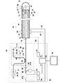
以下、本発明の具体的な実施の形態について図面を用いて説明する。図1は本発明による蛍光断層画像取得装置の実施の形態の概略構成を示す図である。 Hereinafter, specific embodiments of the present invention will be described with reference to the drawings. FIG. 1 is a diagram showing a schematic configuration of an embodiment of a fluorescence tomographic image acquisition apparatus according to the present invention.
本実施の形態による断層画像取得装置は、図1に示すように内視鏡の鉗子口へ挿通可能なプローブ10と、該プローブと接続された光学ユニット30と、プローブ10および光学ユニット30と接続された信号処理ユニット50と、該信号処理ユニット50と接続されたモニタ70とを備えている。また、本蛍光断層画像取得装置は、超音波変調された蛍光から蛍光断層画像を取得する蛍光断層画像取得機能と、超音波変調光断層画像を取得する超音波変調光断層画像取得機能と、光断層画像を取得する光断層画像取得機能と、超音波断層画像を取得する超音波断層画像取得機能とを有している。なお、被検者には、予め腫瘍親和性を有する蛍光薬剤が投与されている。この蛍光薬剤は、波長750nmの励起光が照射された場合には、波長帯域770nm〜900nmの蛍光を発するものである。
As shown in FIG. 1, the tomographic image acquisition apparatus according to the present embodiment is connected to the
また、本蛍光断層画像取得装置は、各断層画像と、蛍光断層画像および超音波変調光断層画像を重畳した重畳断層画像と、光断層画像、超音波変調光断層画像および超音波断層画像を合成し、さらに蛍光断層画像を重畳した合成断層画像と、複数枚の連続した蛍光断層画像に基づいて作成される3次元蛍光断層画像とをモニタへ表示するものである。 The fluorescence tomographic image acquisition device synthesizes each tomographic image, a superimposed tomographic image obtained by superimposing the fluorescent tomographic image and the ultrasonic modulated optical tomographic image, the optical tomographic image, the ultrasonic modulated optical tomographic image, and the ultrasonic tomographic image. Further, the composite tomographic image in which the fluorescent tomographic images are superimposed and the three-dimensional fluorescent tomographic image created based on a plurality of continuous fluorescent tomographic images are displayed on the monitor.
まず、超音波画像取得機能に関わる構成について説明する。プローブ10は、可撓性を有するシース11およびシース11に対して回転可能な回転シース12により覆われている。回転シース12には、不図示の被検部へ対して超音波を照射し、該被検部で反射された反射波(エコー)を受ける超音波トランスデューサ13が設けられている。また、信号処理ユニット50には、該超音波トランスデューサ13へ電気信号である超音波信号を送信し、また該超音波トランスデューサ13から送信される電気信号である反射波信号を受信して、超音波断層情報を生成する超音波信号処理部51と、該超音波信号処理部51と接続されている制御部52が設けられている。超音波トランスデューサ13と超音波信号処理部51との間は、ケーブル14、端子27およびケーブル53により接続されている。端子27は、プローブ10内の後述する光ファイバ15の外筒16の先端部へ周設されたものである。
First, a configuration related to the ultrasonic image acquisition function will be described. The
ケーブル14は端子27に接触し、また、ケーブル53は端子27に接続されている。これにより、回転シース12が回転運動を行った場合でも、ケーブル14、端子27およびケーブル53が常に接続した状態となるため、超音波信号および反射波信号が間断なく伝導するようになっている。
The
超音波信号処理部51は、受信した反射波信号の波形を基に超音波断層情報を生成し、制御部52へ出力する。制御部52は、送信された超音波断層情報に基づいて超音波断層画像を生成する。なお、制御部52は、各部位と接続され、各部位の動作タイミングを制御し、また送信される各断層情報に基づいて、各断層画像を生成するものである。制御部52の動作の詳細は後述する。
The ultrasonic
次に、各光断層画像取得機能に関わる構成について説明する。まずプローブ10の構成について説明する。プローブ10の中心には、ファイバ15が配設されており、ファイバ15の周囲には、可撓性の外筒16が設けられている。外筒16は、可撓性のシース11に覆われている。また外筒16の先端部分は、回転シース12に覆われ、複数のベアリング21により軸支される。回転シース12の基端部はセンタレスモータ22に接続される。センタレスモータ22は、ロータリエンコーダの機能を有しており、センタレスモータ22の回転角度検出部により検出された回転角度を示す信号が、信号線23により制御部52に送られる。
Next, a configuration related to each optical tomographic image acquisition function will be described. First, the configuration of the
ファイバ15の先端には、ファイバ15により導光された光を被検部へ集光し、被検部により反射された反射光あるいは後述する超音波変調光および超音波変調蛍光をファイバ15のコア部へ集光するロッドレンズ17と、各光を直角方向に反射するミラー18が設けられている。なお、ミラー18は、回転シース12に固着され、回転シース12の回転により回転する。また、回転シース12の先端には、ミラー18により反射された光が、射出する光学窓26が設けられている。さらに、ファイバ15の基端側には、集光レンズ19が設けられている。
At the tip of the
またシース11の基端部には、リニア駆動装置24が設けられている。このリニア駆動装置24は、不図示の内視鏡の鉗子口に対して、プローブ10をプローブ10の長手方向に平行に移動するものである。リニア駆動装置24は、リニアエンコーダの機能を有しており、リニアエンコーダの移動距離検出部により検出された移動距離を示す信号が、信号線25により制御部52に送られる。
Further, a
また、回転シース12の先端部の光学窓26の近傍には、ミラー18で反射した光の射出方向と同方向に超音波が照射されるように、前述の超音波トランスデューサ13が取り付けられている。なお、超音波トランスデューサ13を配置する位置は、上記の位置に限ったものでなく、光の照射領域と、超音波の照射領域がほぼ重なる位置であり、かつ光の照射を妨げない位置であれば、どのような位置に配置してもよい。
In addition, the
光学ユニット30は、波長750nmの低コヒーレンス光Lを出射する光源部31と、光源部31より射出された低コヒーレンス光の参照光Lrおよび測定光Lsへ分割および合成を行うファイバ結合光学系32と、参照光Lrの光路上に配され、参照光Lrの光路長を変化させる光路遅延部33と、被検部の所定の深度で反射された測定光Ls’と参照光Lrとの干渉光Lcの光強度を検出する光検出部34とを備えている。また、光検出部34は、後述する超音波変調光および超音波変調蛍光の光強度も検出するものである。
The
光源部31は、SLDなどからなり波長750nmの低コヒーレンス光を出射する光源36と、光源36から出射された低コヒーレンス光を集光する集光レンズ37とを備えている。
The
ファイバ結合光学系32は、光源36から出射された低コヒーレンス光を測定光Lsと参照光Lrとに分割し、また、測定光Lsの被検部の所定の深部からの反射光である測定光Ls’と参照光Lrを合波し、干渉光Lcを得るファイバカプラ39と、参照光Lrに僅かな周波数シフトを生じさせるピエゾ素子40と、ファイバカプラ39を介して光源部31と光路遅延部33を繋ぐファイバ41と、ファイバカプラ39を介して光検出部34と回転シース12の間を導光するファイバ42とを備えている。
The fiber coupling
光路遅延部33は、ファイバ41から射出された参照光Lrを平行光に変換し、また反射された参照光Lrをファイバ41へ入射させる集光レンズ44と、図1における水平方向への移動により参照光Lrの光路長を変化させる参照光ミラー45と、参照光ミラー45を水平方向への移動させる駆動部46とを備えている。
The optical path delay
光検出部34は、干渉光Lcおよび超音波変調光の光強度を検出する光検出器47aと、該光検出器47aの前に配置され、波長が765nm以上の光を直角に反射し、波長が765nmより小さい光を透過するダイクロイックミラー48と、該ダイクロイックミラー47の前に配置される集光レンズ49と、ダイクロイックミラー48で反射された光の光強度を検出する光検出器47bとを備えている。なお、光検出器47bは、後述する超音波変調蛍光の光強度を検出するものである。
The
光検出器47aは、光断層情報生成部54、超音波変調光断層情報生成部55および制御部52と接続され、制御部52の制御により、検出結果を光断層情報生成部54または超音波変調光断層情報生成部55へ出力する。また、光検出器47bは、超音波変調光断層情報生成部55へ接続されている。
The
信号処理ユニット50の光断層情報生成部54では、光検出器47aで検出された干渉光Lcの光強度に基づいて、光断層情報を生成し、制御部52へ出力する。超音波変調光断層情報生成部55では、光検出器47aで検出された超音波変調光の光強度に基づいて超音波変調光断層情報を生成し、光検出器47bで検出された超音波変調蛍光の光強度に基づいて蛍光断層情報を生成して、制御部52へ出力する。
The optical tomographic
次に、以上のように構成された本実施の形態による断層画像取得装置における各断層画像の取得と、各断層画像、重畳断層画像および合成断層画像の生成および表示動作について説明する。 Next, acquisition of each tomographic image and generation and display operations of each tomographic image, superimposed tomographic image, and composite tomographic image in the tomographic image acquisition apparatus according to the present embodiment configured as described above will be described.
患者の体腔内を観察する際には、内視鏡の鉗子口にプローブ10を挿通し、内視鏡を患者の体腔内に挿入し、内視鏡のモニタに表示される画像を基に、目視により内視鏡の挿入部先端を所望の部位まで誘導する。
When observing the inside of the patient's body cavity, the
まず、超音波断層画像を取得して表示する際の動作について説明する。制御部52の制御により、超音波信号処理部51により超音波信号が発振される。この超音波信号は、ケーブル53、端子27およびケーブル14を介して、超音波トランスデューサ13に伝導される。
First, an operation when acquiring and displaying an ultrasonic tomographic image will be described. An ultrasonic signal is oscillated by the ultrasonic
超音波信号が超音波トランスデューサ13により超音波に変換され、被検部に超音波が照射される。被検部で反射された反射波は、超音波トランスデューサ13により電気信号に変換されて、反射波信号として超音波信号処理部51に送信される。超音波信号処理部51は受信した反射波信号の波形を元に超音波断層情報を生成し、制御部52に送信する。
The ultrasonic signal is converted into an ultrasonic wave by the
さらにセンタレスモータ22により回転シース12を回転させることにより超音波の照射方向を移動させ、ファイバ15の長手方向を軸としたラジアル走査を行う。なお、センタレスモータ22の回転角度検出部により検出された回転角度を示す信号が、信号線23により制御部52に送られている。
Further, the rotating
制御部52では、センタレスモータ22の回転角度と、超音波信号処理部51から送信される超音波断層情報に基づいて、ラジアル超音波断層画像を生成し、モニタ70へ出力する。モニタ70には、図2の(A)に示すような超音波断層画像が表示される。
The
また、リニア駆動装置24により、プローブ10のリニア走査を行うことにより、リニア超音波断層画像を取得して表示することもできる。
In addition, by performing linear scanning of the
次に、光断層画像を取得して表示する際の動作について説明する。本実施の形態では、光断層画像取得手段としてOCT装置が搭載されている。制御部52の制御により、光断層画像取得用の低コヒーレンス光が光源部31から射出される。光源36から出射された低コヒーレンス光は、集光レンズ37により集光され、ファイバ41に導入される。
Next, an operation when acquiring and displaying an optical tomographic image will be described. In this embodiment, an OCT apparatus is mounted as an optical tomographic image acquisition unit. Under the control of the
ファイバ41を透過した低コヒーレンス光は、ファイバカプラ39で、ファイバ41内を光路遅延部33の方向へ進行する参照光Lrと、ファイバ42内をシース12の方向へ進行する測定光Lsとに分割される。参照光Lrは光路上に設けられたピエゾ素子40により変調され、参照光Lrと測定光Lsには、僅かな周波数差△fが生じる。
The low-coherence light transmitted through the
ファイバ42に導光された測定光Lsは、レンズ19を介してファイバ15に入射され、ファイバ15内を伝播し、ファイバ15先端から射出され、ロッドレンズ17およびミラー18を介して被検部へ入射される。被検部に入射された測定光Lsのうち被検部の所定の深度で反射された測定光Ls’は、ミラー18、ロッドレンズ17、ファイバ15、レンズ19を介してファイバ42に帰還せしめられる。ファイバ42に帰還せしめられた測定光Ls’は、ファイバカプラ39において、後述するファイバ41に帰還せしめられた参照光Lrと合波される。
The measurement light Ls guided to the
一方、ピエゾ素子40で変調された後の参照光Lrは、ファイバ41を通過し光路遅延部33の集光レンズ44を介して、参照光ミラー45に入射し、この参照光ミラー45で反射され再度集光レンズ44を透過して、ファイバ41に帰還せしめられる。ファイバ41に帰還せしめられた参照光Lrはファイバカプラ39で、上述した測定光Ls’と合波される。
On the other hand, the reference light Lr after being modulated by the piezo element 40 passes through the
ファイバカプラ39で合波された測定光Ls’および参照光Lrは、再び同軸上に重なり、測定光Ls’と参照光Lrが干渉して干渉光Lcと、ファイバ41から射出され、レンズ49およびダイクロイックミラー48を介して、光検出器47aへ入射する。
The measurement light Ls ′ and the reference light Lr combined by the
参照光Lrおよび測定光Ls’は、可干渉距離の短い低コヒーレンス光であるため、低コヒーレンス光が測定光Lsと参照光Lrに分割されたのち、測定光Ls(Ls’) がファイバカプラ39に到達するまでの光路長が、参照光Lrがファイバカプラ39に到達するまでの光路長に等しい場合に両光が干渉し、この干渉する両光の周波数差(△f)で強弱を繰り返すビート信号が発生する。
Since the reference light Lr and the measurement light Ls ′ are low coherence light with a short coherence distance, the measurement light Ls (Ls ′) is split into the
光検出器47aでは、干渉光Lcから上記ビート信号の光強度を検出し、ヘテロダイン検出を行い、被検部の所定深度より反射された測定光Ls’の強度を検出し、光断層情報生成部54へ出力する。
The
なお、波長750nmの測定光Lsが被検部へ照射されると、被検部からは波長770nm〜900nmの蛍光が発せられる。しかし、この蛍光は、ダイクロイックミラー47により直角方向へ反射されるため光検出器47aへ入射することはない。
When the measurement light Ls having a wavelength of 750 nm is irradiated to the test part, fluorescence having a wavelength of 770 nm to 900 nm is emitted from the test part. However, since this fluorescence is reflected by the dichroic mirror 47 in the right angle direction, it does not enter the
光断層情報生成部54では、測定光Ls’の強度に基づいて、光断層情報を生成し、制御部52へ出力する。その後、参照光ミラー45は、駆動部46により、その光軸方向(図中水平方向)に移動され、参照光Lrがファイバカプラ39に到達するまでの光路長が変化する。このため参照光Lrと干渉する測定光Ls(Ls’)の光路長も変化するので、被検部の断層情報を取得する深度も変化する。このように深度を僅かずつ変化させながら、光断層情報を繰り返し取得する。各照射点において、被検部の表面から深さ2mm程度まで光断層情報を取得する。なお、光路遅延部33の駆動部46は、制御部52へ接続され、光路長の情報は逐次制御部へ出力されている。
The optical tomographic
1点における光断層情報の取得が終了すると、センタレスモータ24により回転シース12を僅かに回転させることにより測定光Lsの照射方向を移動させ、再度その照射点における光断層情報を取得する。このようにして、ファイバ15の長手方向を軸としたラジアル走査を行い、被検部を輪切りにした状態の光断層画像を取得する。
When the acquisition of the optical tomographic information at one point is completed, the irradiation direction of the measurement light Ls is moved by slightly rotating the
制御部52では、光路長と、センタレスモータ22の回転角度と、光断層情報生成部54から出力される光断層情報に基づいて、ラジアル光断層画像を生成し、モニタ70へ出力する。モニタ70には、図2の(B)に示すような被検部の表面から深さ2mm程度までの光断層画像が表示される。解像度は、光源36から射出される低コヒーレンス光の波長およびコヒーレンス長により変化するが、必要であれば数μmまで上げることができる。
The
さらに、超音波変調光断層画像および蛍光断層画像を取得して表示する際の動作について説明する。制御部52の制御により、超音波信号処理部51から超音波信号が発振され、超音波トランスデューサ13より、被検部に超音波が照射される。
Furthermore, an operation when acquiring and displaying an ultrasonically modulated optical tomographic image and a fluorescent tomographic image will be described. Under the control of the
同時に、低コヒーレンス光が光源部31から射出される。光源36から出射された光は、ファイバ41を伝播し、ファイバカプラ39を介して、ファイバ42を、プローブ10の方向へ伝播する。ファイバ42を伝播した光は、レンズ19を介してファイバ15に入射され、ファイバ15内を伝播し、ファイバ15先端から射出され、ロッドレンズ17およびミラー18を介して被検部へ照射される。
At the same time, low-coherence light is emitted from the
この際、被検部には超音波が照射されている。このため、被検部においては弾性波が光に対して屈折率分引を形成する。すなわち、被検部において組織の粗密状態が形成される。このような場合には、光が被検部を進行すると、組織の粗密状態が光に対して作用し、光が変調される。この変調された光(反射光)を解析処理することにより、光が照射された被検部の断層情報を取得することができる。超音波の作用を受けた被検部で反射された超音波変調光は、ミラー18、ロッドレンズ17、ファイバ15、レンズ19を介してファイバ42に帰還せしめられ、ファイバ42の他端から射出され、レンズ49で集光され、ダイクロイックミラー48を透過し、光検出器47aに入射する。光検出器47aは、超音波変調光の強度を検出する。
At this time, ultrasonic waves are applied to the portion to be examined. For this reason, the elastic wave forms a refractive index subtraction with respect to the light in the test portion. That is, a tissue density state is formed in the test portion. In such a case, when light travels through the region to be examined, the density of the tissue acts on the light, and the light is modulated. By analyzing the modulated light (reflected light), it is possible to acquire tomographic information of the test portion irradiated with the light. The ultrasonic modulated light reflected by the test portion subjected to the action of ultrasonic waves is returned to the
制御部52の制御により、光検出器47aの出力は、超音波変調光断層情報生成部55へ出力される。なお、超音波変調光断層情報生成部55へは、超音波信号処理部51から超音波信号が出力されている。超音波変調光断層情報生成部55では、超音波信号および光検出器47aで検出された反射光の強度に基づいて、超音波変調光断層情報を生成する。なお、超音波信号の発振タイミングが既知であるため、反射光を1回検出するのみで、被検部の表面から、深さ5mm〜10mm程度までの超音波変調断層情報を取得することができる。また、解像度は、超音波の発振周波数や、光の集光度等により変化するが、必要であれば数十μmまで上げることができる。
Under the control of the
また、被検部には、予め蛍光薬剤が付与されているため、被検部に光が照射されると、被検部からは波長帯域770nm〜900nmの蛍光が発せられる。また被検部には超音波が照射されているため、被検部では組織の粗密状態が形成されている。このような状態で、蛍光が被検部から発せられると、組織の粗密状態が蛍光に対して作用し、蛍光が変調される。この変調された蛍光、すなわち超音波変調蛍光は、反射光(超音波変調光)と同様に、ファイバ15およびファイバ42を伝播し、ファイバ42から射出され、レンズ49により集光される。超音波変調蛍光は、波長帯域が770nm〜900nmであるため、ダイクロイックミラー48で反射され、光検出器47bに入射する。光検出器47bは、超音波変調蛍光の光強度を検出し、超音波変調光断層情報生成部55へ出力する。超音波変調光断層情報生成部55では、超音波信号および光検出器47bで検出された超音波変調蛍光の強度に基づいて、超音波変調蛍光断層情報を生成する。なお、超音波信号の発振タイミングが既知であるため、反射光を1回検出するのみで、被検部の表面から深さ5mm〜10mm程度までの超音波変調蛍光断層情報を取得することができる。また、解像度は、超音波の発振周波数や、光(励起光)の集光度等により変化するが、必要であれば数十μmまで上げることができる。
Moreover, since the fluorescent part is previously given to the test part, when the test part is irradiated with light, the test part emits fluorescence having a wavelength band of 770 nm to 900 nm. In addition, since the ultrasonic wave is irradiated to the test part, a tissue dense state is formed in the test part. In this state, when fluorescence is emitted from the test part, the tissue density state acts on the fluorescence, and the fluorescence is modulated. This modulated fluorescence, that is, ultrasound-modulated fluorescence, propagates through the
1点における超音波変調光断層情報および超音波変調蛍光断層情報の取得が終了すると、センタレスモータ24により回転シース12を僅かに回転させることにより光の照射方向を移動させ、再度その照射点における超音波変調光断層情報および超音波変調蛍光断層情報を取得する。このようにして、ファイバ15の長手方向を軸としたラジアル走査を行い、被検部を輪切りにした状態の超音波変調光断層情報および超音波変調蛍光断層情報を取得する。
When the acquisition of the ultrasonically modulated optical tomographic information and the ultrasonically modulated fluorescent tomographic information at one point is completed, the
制御部52では、センタレスモータ22の回転角度と、超音波変調光断層情報生成部55から出力される超音波変調光断層情報に基づいて、ラジアル光断層画像を生成し、モニタ70へ出力する。モニタ70には、図2の(C)に示すような超音波変調光断層画像が表示される。また、制御部52では、同時に、センタレスモータ22の回転角度と、超音波変調光断層情報生成部55から出力される超音波変調蛍光断層情報に基づいて、ラジアル蛍光断層画像を生成し、モニタ70へ出力する。モニタ70には、図2の(D)に示すような蛍光断層画像が表示される。蛍光断層画像では、被検部に腫瘍がある場合には、その腫瘍の位置や大きさ等が画像化される。
The
さらに、制御部52は、超音波変調光断層画像と蛍光断層画像とを重畳させ、図3に示すような重畳画像を生成し、モニタ70へ表示することもできる。超音波変調光断層画像と蛍光断層画像とは、同時に取得されているため、画像位置あわせを容易に行うことができる。観察者はこのような重畳画像を観察することにより、被検部の断層形状と、蛍光薬剤の分布状態、すなわち腫瘍の有無や大きさなど同時に知ることができる。
Further, the
さらに、光断層画像と、超音波変調光断層画像と、超音波断層画像を組合わせ、さらに蛍光断層画像を重畳した合成断層画像(ラジアル)を取得して表示する際の動作について説明する。 Furthermore, an operation when a combined tomographic image (radial) obtained by combining an optical tomographic image, an ultrasonically modulated optical tomographic image, and an ultrasonic tomographic image and further superimposing a fluorescent tomographic image is displayed will be described.
まず、被検部の光断層画像と、超音波変調光断層画像と、蛍光断層画像と、超音波断層画像とを取得する。上述のように個々にラジアル断層画像を取得してもよいが、まず被検部の所定の点に関し、光断層情報と、超音波変調光断層情報と、超音波変調蛍光断層情報と、超音波断層情報とを取得し、その後回転シース12を僅かに回転させて次の点で各断層情報を取得することを繰り返し、回転シース12の一回転で、4種類の断層画像を取得してもよい。なお、超音波断層情報と、超音波変調光断層情報および超音波変調蛍光断層情報とは、同時に取得してもよい。
First, an optical tomographic image, an ultrasonically modulated optical tomographic image, a fluorescence tomographic image, and an ultrasonic tomographic image of the test part are acquired. As described above, radial tomographic images may be acquired individually, but first, optical tomographic information, ultrasonically modulated optical tomographic information, ultrasonically modulated fluorescent tomographic information, and ultrasonic waves with respect to a predetermined point of the test portion. It is also possible to acquire the tomographic information, and then rotate the
各断層画像を一旦不図示の記憶部へ記憶した後、制御部52は、光断層画像から、被検部の低深度領域(表面から深さ2mm程度まで)の断層画像である低深度断層画像を選択し、超音波変調光断層画像から被検部の中深度領域(深さ2mm程度から、深さ5mm〜10mm程度まで)の断層画像である中深度断層画像を選択し、超音波断層画像から被検部の高深度領域(深さ5mm〜10mm程度から30mmまで)の断層画像である高深度断層画像を選択し、低深度断層画像と中深度断層画像と高深度断層画像とを合成し、さらに、蛍光断層画像を重畳して、合成断層画像を生成して、モニタ70へ出力する。モニタ70には、図4の(A)に示すようなラジアル合成断層画像が表示される。
After each tomographic image is temporarily stored in a storage unit (not shown), the
この合成断層画像では、図3の(B)に示すように被検部の表面化から2mm程度までの低深度領域は、光断層画像取得手段により取得した解像度数μmの高解像度断層画像で表示し、2mm程度から、5mm〜10mm程度までの中深度領域は、超音波変調光断層画像手段により取得した解像度数十μmの断層画像で表示し、5mm〜10mm程度から30mmまでの高深度領域は、超音波変調断層画像手段により取得した解像度数百μmの断層画像で表示することができ、この合成断層画像の観察者は、組織の形状等を容易に観察することができる。また、蛍光断層画像が重畳されているため、腫瘍の有無や大きさなども同時に知ることができる。 In this synthetic tomographic image, as shown in FIG. 3B, a low-depth region from the surface of the test portion to about 2 mm is displayed as a high-resolution tomographic image having a resolution of several μm acquired by the optical tomographic image acquiring means. An intermediate depth region from about 2 mm to about 5 mm to 10 mm is displayed as a tomographic image having a resolution of several tens of μm acquired by the ultrasonic modulation optical tomographic image means, and a high depth region from about 5 mm to about 10 mm to 30 mm is A tomographic image having a resolution of several hundreds of μm acquired by the ultrasonic modulation tomographic image means can be displayed, and an observer of this synthesized tomographic image can easily observe the shape of the tissue and the like. In addition, since the fluorescence tomographic images are superimposed, the presence / absence and size of the tumor can be known at the same time.
さらに、ラジアル走査およびリニア走査を繰り返し、複数枚の連続した蛍光断層画像を取得し、該複数枚の連続した蛍光断層画像に、像回復処理などの解析処理を施し、3次元蛍光断層画像を生成し、モニタ70へ表示することもできる。観察者は、被検部の状態をより容易に観察することができる。
Furthermore, radial scanning and linear scanning are repeated to acquire a plurality of continuous fluorescent tomographic images, and analysis processing such as image restoration processing is performed on the plurality of continuous fluorescent tomographic images to generate a three-dimensional fluorescent tomographic image. It can also be displayed on the
以上の説明で明らかなように、本実施の形態の蛍光断層画像取得装置は、被検部へ超音波と励起光を同時に照射し、超音波の作用を受けた前記被検部から発せられる超音波変調蛍光に基づいて、被検部の蛍光断層画像を取得する蛍光断層画像取得手段を備えたことにより、被検部の表面から深さ数mm程度まで、高い解像度(上限数十μm)で蛍光断層画像を取得することができる。このため、例えば被検部に予め腫瘍親和性を有する蛍光薬剤を付与されている場合であれば、被検部における腫瘍の有無、あるいは腫瘍の位置や大きさ等を蛍光断層画像を観察することにより知ることができる。 As is clear from the above description, the fluorescence tomographic image acquisition apparatus according to the present embodiment irradiates ultrasonic waves and excitation light onto the test part at the same time, and the supersonic wave emitted from the test part subjected to the action of the ultrasonic waves. By providing a fluorescent tomographic image acquisition means for acquiring a fluorescent tomographic image of the test part based on the sound wave modulation fluorescence, the surface of the test part has a high resolution (upper tens of μm) to a depth of about several millimeters. A fluorescence tomographic image can be acquired. For this reason, for example, if a fluorescent agent having a tumor affinity has been given to the test part in advance, the presence or absence of the tumor in the test part or the position and size of the tumor should be observed on the fluorescence tomographic image. You can know more.
なお、上記実施の形態においては、ラジアル合成断層画像を生成したが、リニア走査により各断層画像を取得して、リニア合成断層画像を取得して表示してもよい。また、ラジアル走査とリニア走査を組み合わせることにより3次元断層画像を取得して、3次元合成断層画像を生成してもよい。 In the above embodiment, a radial composite tomographic image is generated, but each tomographic image may be acquired by linear scanning, and a linear composite tomographic image may be acquired and displayed. Alternatively, a three-dimensional tomographic image may be obtained by combining radial scanning and linear scanning to generate a three-dimensional synthetic tomographic image.
さらに、本実施の形態においてはプローブへ各断層画像の取得手段を組み込んだが、内視鏡挿入部本体に、各断層画像の取得手段を組み込んだものとすることもできる。 Furthermore, in the present embodiment, each tomographic image acquisition means is incorporated into the probe, but each tomographic image acquisition means may be incorporated into the endoscope insertion section main body.
10 プローブ
12 回転シース
13 超音波トランスデューサ
15 ファイバ
16 外筒
17 ロッドレンズ
18 ミラー
21 ベアリング
22 センタレスモータ
24 リニア駆動装置
30 光学ユニット
31 光源部
32 ファイバ結合光学系
33 光路遅延部
34 光検出部
47a、47b 光検出器
48 ダイクロイックミラー
50 信号処理ユニット
51 超音波信号処理部
52 制御部
55 超音波変調光断層情報生成部
70 モニタ
DESCRIPTION OF
Claims (4)
前記蛍光断層画像取得手段が、複数枚の上記蛍光断層画像から3次元蛍光断層画像を生成する3次元蛍光断層画像生成手段を備えたものであることを特徴とする蛍光断層画像取得装置。 Based on the ultrasonically modulated fluorescence emitted from the test portion that is irradiated with the first ultrasonic wave and the excitation light to the test portion and receives the action of the first ultrasonic wave, the fluorescence tomography of the test portion A fluorescence tomographic image acquisition means for acquiring an image;
The fluorescent tomographic image obtaining means, a plurality of fluorescent tomographic image acquisition apparatus you characterized in that with a three-dimensional fluorescence tomographic image generating means for generating a three-dimensional fluorescence tomographic image from the fluorescent tomographic image.
前記被検部へ第2の超音波と第1の光とを同時に照射し、前記第2の超音波の作用を受けた前記被検部で反射した超音波変調反射光に基づいて、前記被検部の超音波変調光断層画像を取得する超音波変調光断層画像取得手段を備えたことを特徴とする蛍光断層画像取得装置。 Based on the ultrasonically modulated fluorescence emitted from the test portion that is irradiated with the first ultrasonic wave and the excitation light to the test portion and receives the action of the first ultrasonic wave, the fluorescence tomography of the test portion Fluorescence tomographic image acquisition means for acquiring an image;
The second ultrasonic wave and the first light are simultaneously irradiated to the test part, and the test object is reflected on the basis of the ultrasonic modulated reflected light reflected by the test part subjected to the action of the second ultrasonic wave. fluorescent tomographic image acquisition apparatus you comprising the ultrasound modulated optical tomographic image acquisition unit configured to acquire ultrasound modulated optical tomographic image of the inspection unit.
前記被検部へ第2の光を照射し、前記被検部で反射した前記第2の光の反射光に基づいて前記被検部の光断層画像を生成する光断層画像生成手段を備えたことを特徴とする蛍光断層画像取得装置。 Based on the ultrasonically modulated fluorescence emitted from the test portion that is irradiated with the first ultrasonic wave and the excitation light to the test portion and receives the action of the first ultrasonic wave, the fluorescence tomography of the test portion Fluorescence tomographic image acquisition means for acquiring an image;
Optical tomographic image generation means for generating an optical tomographic image of the test part based on the reflected light of the second light reflected by the test part and irradiating the test part with the second light fluorescent tomographic image acquisition apparatus you wherein a.
前記被検部へ第3の超音波を照射し、前記被検部で反射した前記超音波の反射波に基づいて前記被検部の超音波断層画像を生成する超音波断層画像生成手段を備えたことを特徴とする蛍光断層画像取得装置。 Based on the ultrasonically modulated fluorescence emitted from the test portion that is irradiated with the first ultrasonic wave and the excitation light to the test portion and receives the action of the first ultrasonic wave, the fluorescence tomography of the test portion Fluorescence tomographic image acquisition means for acquiring an image;
Ultrasonic tomographic image generation means for generating an ultrasonic tomographic image of the test part based on a reflected wave of the ultrasonic wave reflected by the test part and irradiating the test part with a third ultrasonic wave fluorescent tomographic image acquisition apparatus you characterized in that the.
Priority Applications (3)
| Application Number | Priority Date | Filing Date | Title |
|---|---|---|---|
| JP2005018347A JP4619803B2 (en) | 2005-01-26 | 2005-01-26 | Fluorescence tomographic image acquisition device |
| EP06001611A EP1685795B1 (en) | 2005-01-26 | 2006-01-26 | Apparatus for acquiring tomographic image formed by ultrasound-modulated fluorescence |
| US11/339,526 US7620445B2 (en) | 2005-01-26 | 2006-01-26 | Apparatus for acquiring tomographic image formed by ultrasound-modulated fluorescence |
Applications Claiming Priority (1)
| Application Number | Priority Date | Filing Date | Title |
|---|---|---|---|
| JP2005018347A JP4619803B2 (en) | 2005-01-26 | 2005-01-26 | Fluorescence tomographic image acquisition device |
Publications (3)
| Publication Number | Publication Date |
|---|---|
| JP2006204431A JP2006204431A (en) | 2006-08-10 |
| JP2006204431A5 JP2006204431A5 (en) | 2007-08-30 |
| JP4619803B2 true JP4619803B2 (en) | 2011-01-26 |
Family
ID=36272483
Family Applications (1)
| Application Number | Title | Priority Date | Filing Date |
|---|---|---|---|
| JP2005018347A Expired - Fee Related JP4619803B2 (en) | 2005-01-26 | 2005-01-26 | Fluorescence tomographic image acquisition device |
Country Status (3)
| Country | Link |
|---|---|
| US (1) | US7620445B2 (en) |
| EP (1) | EP1685795B1 (en) |
| JP (1) | JP4619803B2 (en) |
Cited By (1)
| Publication number | Priority date | Publication date | Assignee | Title |
|---|---|---|---|---|
| KR101356621B1 (en) | 2012-04-27 | 2014-02-04 | 한국광기술원 | Fluorescence-photoacoustic signal optical probe for the detection of fluorescence and photoacoustic signal by using transducer equipped with optical fiber |
Families Citing this family (38)
| Publication number | Priority date | Publication date | Assignee | Title |
|---|---|---|---|---|
| US7918795B2 (en) | 2005-02-02 | 2011-04-05 | Gynesonics, Inc. | Method and device for uterine fibroid treatment |
| US11259825B2 (en) | 2006-01-12 | 2022-03-01 | Gynesonics, Inc. | Devices and methods for treatment of tissue |
| US20070238997A1 (en) * | 2006-03-29 | 2007-10-11 | Estelle Camus | Ultrasound and fluorescence imaging |
| US8206300B2 (en) | 2008-08-26 | 2012-06-26 | Gynesonics, Inc. | Ablation device with articulated imaging transducer |
| US10595819B2 (en) | 2006-04-20 | 2020-03-24 | Gynesonics, Inc. | Ablation device with articulated imaging transducer |
| WO2007123518A1 (en) * | 2006-04-21 | 2007-11-01 | Cedars-Sinai Medical Center | Multiple imaging and/or spectroscopic modality probe |
| WO2008005554A2 (en) * | 2006-07-06 | 2008-01-10 | University Of Connecticut | Method and apparatus for medical imaging using near-infrared optical tomography, fluorence tomography combined with ultrasound |
| JP5314841B2 (en) * | 2006-08-22 | 2013-10-16 | オリンパス株式会社 | Endoscope device and endoscope probe |
| DE102006050885B4 (en) * | 2006-10-27 | 2016-11-03 | Siemens Healthcare Gmbh | Device for generating tissue section images |
| JP2008237236A (en) * | 2007-03-23 | 2008-10-09 | Olympus Medical Systems Corp | Endoscope and biological observation system |
| JP2008237235A (en) * | 2007-03-23 | 2008-10-09 | Olympus Medical Systems Corp | Endoscope and biological observation system |
| US20090005685A1 (en) | 2007-06-29 | 2009-01-01 | Canon Kabushiki Kaisha | Ultrasonic probe and inspection apparatus equipped with the ultrasonic probe |
| JP2009066110A (en) * | 2007-09-12 | 2009-04-02 | Canon Inc | Measurement apparatus |
| US8088072B2 (en) | 2007-10-12 | 2012-01-03 | Gynesonics, Inc. | Methods and systems for controlled deployment of needles in tissue |
| JP5340648B2 (en) | 2008-06-12 | 2013-11-13 | オリンパスメディカルシステムズ株式会社 | Subject information calculation apparatus and subject information calculation method |
| JP5255524B2 (en) * | 2008-07-04 | 2013-08-07 | 株式会社ニデック | Optical tomographic imaging device, optical tomographic image processing device. |
| US20100094134A1 (en) * | 2008-10-14 | 2010-04-15 | The University Of Connecticut | Method and apparatus for medical imaging using near-infrared optical tomography combined with photoacoustic and ultrasound guidance |
| WO2010095487A1 (en) * | 2009-02-23 | 2010-08-26 | オリンパスメディカルシステムズ株式会社 | Organism observation device and organism tomogram creating method |
| US8262574B2 (en) | 2009-02-27 | 2012-09-11 | Gynesonics, Inc. | Needle and tine deployment mechanism |
| US20120127557A1 (en) * | 2010-11-19 | 2012-05-24 | Canon Kabushiki Kaisha | Apparatus and method for irradiating a medium |
| US9192303B2 (en) | 2011-12-19 | 2015-11-24 | The Regents Of The University Of California | Temperature-modulated fluorescence tomography |
| US20140066819A1 (en) * | 2012-04-13 | 2014-03-06 | Bruker Biospin Corporation | Luminescence-guided focused ultrasound apparatus and method |
| US10267786B2 (en) | 2013-01-24 | 2019-04-23 | Board Of Regents, The University Of Texas System | Systems and methods for high-resolution imaging |
| US10379109B2 (en) | 2013-01-24 | 2019-08-13 | Board Of Regents, The University Of Texas System | Systems and methods for high-resolution imaging |
| JP6049209B2 (en) * | 2014-01-28 | 2016-12-21 | 富士フイルム株式会社 | Photoacoustic measurement probe and photoacoustic measurement apparatus including the same |
| AU2016215058B2 (en) * | 2015-02-06 | 2021-06-24 | Board Of Regents, The University Of Texas System | Systems and methods for high-resolution imaging |
| JP6588256B2 (en) * | 2015-07-06 | 2019-10-09 | オリンパス株式会社 | Endoscopy data recording system |
| JP6594679B2 (en) * | 2015-07-06 | 2019-10-23 | オリンパス株式会社 | Endoscopy data recording system |
| EP3248531A1 (en) * | 2016-05-23 | 2017-11-29 | Leica Instruments (Singapore) Pte. Ltd. | Medical observation device, such as a microscope or an endoscope, and method using a pseudo-color pattern having temporal and/or spatial modulation |
| US20180092538A1 (en) * | 2016-06-08 | 2018-04-05 | Massachusetts Institute Of Technology | Systems and methods for dual-mode imaging using optical coherence tomography and fluorescence imaging |
| CA3043314A1 (en) | 2016-11-11 | 2018-05-17 | Gynesonics, Inc. | Controlled treatment of tissue and dynamic interaction with, and comparison of, tissue and/or treatment data |
| US10335036B2 (en) | 2017-11-22 | 2019-07-02 | Hi Llc | Pulsed ultrasound modulated optical tomography using lock-in camera |
| US10016137B1 (en) | 2017-11-22 | 2018-07-10 | Hi Llc | System and method for simultaneously detecting phase modulated optical signals |
| US11913883B2 (en) * | 2018-03-06 | 2024-02-27 | Board Of Regents, The University Of Texas System | Highly specific tissue imaging |
| US10368752B1 (en) | 2018-03-08 | 2019-08-06 | Hi Llc | Devices and methods to convert conventional imagers into lock-in cameras |
| US11206985B2 (en) | 2018-04-13 | 2021-12-28 | Hi Llc | Non-invasive optical detection systems and methods in highly scattering medium |
| US11857316B2 (en) | 2018-05-07 | 2024-01-02 | Hi Llc | Non-invasive optical detection system and method |
| JP2022501152A (en) * | 2018-10-05 | 2022-01-06 | キヤノン ユーエスエイ, インコーポレイテッドCanon U.S.A., Inc | Overmolded distal optics for intracavitary optical probes |
Citations (3)
| Publication number | Priority date | Publication date | Assignee | Title |
|---|---|---|---|---|
| JP2002505900A (en) * | 1998-03-09 | 2002-02-26 | スペクトラサイエンス,インコーポレイティド | Optical student examination device and tissue diagnosis method |
| JP2004105725A (en) * | 2002-08-30 | 2004-04-08 | Olympus Corp | Endoscope system and endoscope inserting action program |
| JP2006055396A (en) * | 2004-08-20 | 2006-03-02 | Masaki Kobayashi | Fluorescent tomogram measuring apparatus |
Family Cites Families (20)
| Publication number | Priority date | Publication date | Assignee | Title |
|---|---|---|---|---|
| US6002958A (en) * | 1992-12-24 | 1999-12-14 | Dynamics Imaging, Inc. | Method and apparatus for diagnostics of internal organs |
| US5999836A (en) | 1995-06-06 | 1999-12-07 | Nelson; Robert S. | Enhanced high resolution breast imaging device and method utilizing non-ionizing radiation of narrow spectral bandwidth |
| US6041248A (en) * | 1997-05-07 | 2000-03-21 | The Texas A&M University System | Method and apparatus for frequency encoded ultrasound-modulated optical tomography of dense turbid media |
| US6245015B1 (en) * | 1998-12-07 | 2001-06-12 | General Electric Company | Photosonic diffusion wave-based tumor detector |
| IL129398A (en) * | 1999-04-12 | 2005-05-17 | Israel Atomic Energy Comm | Metabolism monitoring or body organs |
| EP1090582B1 (en) | 1999-10-01 | 2001-05-23 | Karl Storz GmbH & Co. KG | Imaging method for determining condition of tissue |
| IL137447A (en) * | 2000-07-23 | 2007-03-08 | Israel Atomic Energy Comm | Apparatus and method for probing light absorbing agents in biological tissues |
| EP1379284A4 (en) | 2001-01-05 | 2007-07-25 | Gen Hospital | Activatable imaging probes |
| US6609015B2 (en) * | 2001-01-18 | 2003-08-19 | Koninklijke Philips Electronics N.V. | Analysis of a composition |
| IL141135A0 (en) * | 2001-01-28 | 2002-02-10 | Israel Atomic Energy Comm | Method for imaging in a turbid medium |
| US7338651B2 (en) * | 2001-09-04 | 2008-03-04 | Texas Tech University System | Multi-use multimodal imaging chelates |
| JP2005514144A (en) | 2002-01-09 | 2005-05-19 | ネオガイド システムズ, インコーポレイテッド | Apparatus and method for spectroscopic examination of the colon |
| WO2004075032A2 (en) * | 2003-02-19 | 2004-09-02 | Sicel Technologies Inc. | In vivo fluorescence sensors, systems, and related methods operating in conjunction with fluorescent analytes |
| JP2005018347A (en) | 2003-06-25 | 2005-01-20 | Seiko Epson Corp | Charging information managing device and system |
| DK1675501T3 (en) * | 2003-09-12 | 2013-11-18 | Or Nim Medical Ltd | Non-invasive optical monitoring of an area of interest |
| US20050107694A1 (en) * | 2003-11-17 | 2005-05-19 | Jansen Floribertus H. | Method and system for ultrasonic tagging of fluorescence |
| US7144370B2 (en) * | 2004-05-12 | 2006-12-05 | General Electric Company | Method and apparatus for imaging of tissue using multi-wavelength ultrasonic tagging of light |
| WO2006027738A1 (en) * | 2004-09-10 | 2006-03-16 | Philips Intellectual Property & Standards Gmbh | Compounds and methods for combined optical-ultrasound imaging |
| US20060224053A1 (en) * | 2005-03-30 | 2006-10-05 | Skyline Biomedical, Inc. | Apparatus and method for non-invasive and minimally-invasive sensing of venous oxygen saturation and pH levels |
| US20070093702A1 (en) * | 2005-10-26 | 2007-04-26 | Skyline Biomedical, Inc. | Apparatus and method for non-invasive and minimally-invasive sensing of parameters relating to blood |
-
2005
- 2005-01-26 JP JP2005018347A patent/JP4619803B2/en not_active Expired - Fee Related
-
2006
- 2006-01-26 US US11/339,526 patent/US7620445B2/en not_active Expired - Fee Related
- 2006-01-26 EP EP06001611A patent/EP1685795B1/en not_active Expired - Fee Related
Patent Citations (3)
| Publication number | Priority date | Publication date | Assignee | Title |
|---|---|---|---|---|
| JP2002505900A (en) * | 1998-03-09 | 2002-02-26 | スペクトラサイエンス,インコーポレイティド | Optical student examination device and tissue diagnosis method |
| JP2004105725A (en) * | 2002-08-30 | 2004-04-08 | Olympus Corp | Endoscope system and endoscope inserting action program |
| JP2006055396A (en) * | 2004-08-20 | 2006-03-02 | Masaki Kobayashi | Fluorescent tomogram measuring apparatus |
Cited By (1)
| Publication number | Priority date | Publication date | Assignee | Title |
|---|---|---|---|---|
| KR101356621B1 (en) | 2012-04-27 | 2014-02-04 | 한국광기술원 | Fluorescence-photoacoustic signal optical probe for the detection of fluorescence and photoacoustic signal by using transducer equipped with optical fiber |
Also Published As
| Publication number | Publication date |
|---|---|
| EP1685795B1 (en) | 2011-10-05 |
| JP2006204431A (en) | 2006-08-10 |
| US7620445B2 (en) | 2009-11-17 |
| EP1685795A1 (en) | 2006-08-02 |
| US20060184049A1 (en) | 2006-08-17 |
Similar Documents
| Publication | Publication Date | Title |
|---|---|---|
| JP4619803B2 (en) | Fluorescence tomographic image acquisition device | |
| JP3772002B2 (en) | In-subject tomographic imaging system | |
| JP4768494B2 (en) | Diagnostic imaging apparatus and processing method thereof | |
| JP5340648B2 (en) | Subject information calculation apparatus and subject information calculation method | |
| US7999945B2 (en) | Optical coherence tomography / acoustic radiation force imaging probe | |
| JP2006204430A (en) | Tomographic image acquisition device | |
| JP3842101B2 (en) | Endoscope device | |
| JP4838032B2 (en) | Diagnostic imaging apparatus and processing method thereof | |
| JP5118867B2 (en) | Endoscope observation apparatus and operation method of endoscope | |
| JP5192846B2 (en) | Biological observation apparatus and method of operating biological observation apparatus | |
| JP5559145B2 (en) | Diagnostic imaging apparatus and operating method thereof | |
| JP2002153472A (en) | Image diagnostic device | |
| WO2011039983A1 (en) | Diagnostic imaging apparatus and method for controlling same | |
| JP4939237B2 (en) | SUBJECT INFORMATION ANALYSIS DEVICE, ENDOSCOPE DEVICE, AND SUBJECT INFORMATION ANALYSIS METHOD | |
| JP2008545500A (en) | Laser optical feedback tomography sensor and method | |
| JP2010142422A (en) | Optical probe and optical observation apparatus | |
| JP2011200596A (en) | Optical coherent cross-sectional image forming apparatus and control method of the same | |
| KR101737440B1 (en) | Integrated intravascular photoacoustic/ultrasound catheter, and system and method for co-registered imaging | |
| JP2008200283A (en) | Optical probe and optical tomographic image acquiring apparatus | |
| JP2011072401A (en) | Optical probe and endoscope apparatus | |
| JP2011072596A (en) | Diagnostic imaging apparatus and method for controlling same | |
| JP2006192059A (en) | Tomographic measuring instrument | |
| JP2006204429A (en) | Tomogram acquiring apparatus | |
| JP2002143088A (en) | Emr(endoscopic mucosal rejection) device | |
| JP2008142454A (en) | Medical diagnostic probe and medical diagnostic system |
Legal Events
| Date | Code | Title | Description |
|---|---|---|---|
| A711 | Notification of change in applicant |
Free format text: JAPANESE INTERMEDIATE CODE: A712 Effective date: 20061209 |
|
| A521 | Request for written amendment filed |
Free format text: JAPANESE INTERMEDIATE CODE: A523 Effective date: 20070718 |
|
| A621 | Written request for application examination |
Free format text: JAPANESE INTERMEDIATE CODE: A621 Effective date: 20070718 |
|
| A977 | Report on retrieval |
Free format text: JAPANESE INTERMEDIATE CODE: A971007 Effective date: 20100401 |
|
| A131 | Notification of reasons for refusal |
Free format text: JAPANESE INTERMEDIATE CODE: A131 Effective date: 20100720 |
|
| A521 | Request for written amendment filed |
Free format text: JAPANESE INTERMEDIATE CODE: A523 Effective date: 20100913 |
|
| TRDD | Decision of grant or rejection written | ||
| A01 | Written decision to grant a patent or to grant a registration (utility model) |
Free format text: JAPANESE INTERMEDIATE CODE: A01 Effective date: 20101005 |
|
| A01 | Written decision to grant a patent or to grant a registration (utility model) |
Free format text: JAPANESE INTERMEDIATE CODE: A01 |
|
| A61 | First payment of annual fees (during grant procedure) |
Free format text: JAPANESE INTERMEDIATE CODE: A61 Effective date: 20101027 |
|
| FPAY | Renewal fee payment (event date is renewal date of database) |
Free format text: PAYMENT UNTIL: 20131105 Year of fee payment: 3 |
|
| R150 | Certificate of patent or registration of utility model |
Ref document number: 4619803 Country of ref document: JP Free format text: JAPANESE INTERMEDIATE CODE: R150 Free format text: JAPANESE INTERMEDIATE CODE: R150 |
|
| R250 | Receipt of annual fees |
Free format text: JAPANESE INTERMEDIATE CODE: R250 |
|
| R250 | Receipt of annual fees |
Free format text: JAPANESE INTERMEDIATE CODE: R250 |
|
| R250 | Receipt of annual fees |
Free format text: JAPANESE INTERMEDIATE CODE: R250 |
|
| R250 | Receipt of annual fees |
Free format text: JAPANESE INTERMEDIATE CODE: R250 |
|
| R250 | Receipt of annual fees |
Free format text: JAPANESE INTERMEDIATE CODE: R250 |
|
| R250 | Receipt of annual fees |
Free format text: JAPANESE INTERMEDIATE CODE: R250 |
|
| LAPS | Cancellation because of no payment of annual fees |