JP4619008B2 - Method and apparatus for modeling a gas turbine engine - Google Patents
Method and apparatus for modeling a gas turbine engine Download PDFInfo
- Publication number
- JP4619008B2 JP4619008B2 JP2004006361A JP2004006361A JP4619008B2 JP 4619008 B2 JP4619008 B2 JP 4619008B2 JP 2004006361 A JP2004006361 A JP 2004006361A JP 2004006361 A JP2004006361 A JP 2004006361A JP 4619008 B2 JP4619008 B2 JP 4619008B2
- Authority
- JP
- Japan
- Prior art keywords
- detonation
- engine
- pulse
- gas turbine
- tube
- Prior art date
- Legal status (The legal status is an assumption and is not a legal conclusion. Google has not performed a legal analysis and makes no representation as to the accuracy of the status listed.)
- Expired - Fee Related
Links
- 238000000034 method Methods 0.000 title description 17
- 238000005474 detonation Methods 0.000 claims description 114
- 238000013461 design Methods 0.000 claims description 23
- 239000000446 fuel Substances 0.000 claims description 10
- 238000013507 mapping Methods 0.000 claims description 4
- 239000007789 gas Substances 0.000 description 55
- 238000010586 diagram Methods 0.000 description 10
- 238000002485 combustion reaction Methods 0.000 description 9
- 239000000567 combustion gas Substances 0.000 description 7
- 239000000203 mixture Substances 0.000 description 7
- 230000035939 shock Effects 0.000 description 4
- 238000004513 sizing Methods 0.000 description 3
- 238000011144 upstream manufacturing Methods 0.000 description 3
- 238000004891 communication Methods 0.000 description 2
- 230000007613 environmental effect Effects 0.000 description 1
- 238000000605 extraction Methods 0.000 description 1
- 239000012530 fluid Substances 0.000 description 1
- 230000003993 interaction Effects 0.000 description 1
- 238000012986 modification Methods 0.000 description 1
- 230000004048 modification Effects 0.000 description 1
- 238000012544 monitoring process Methods 0.000 description 1
- 230000003252 repetitive effect Effects 0.000 description 1
Images


Classifications
-
- F—MECHANICAL ENGINEERING; LIGHTING; HEATING; WEAPONS; BLASTING
- F02—COMBUSTION ENGINES; HOT-GAS OR COMBUSTION-PRODUCT ENGINE PLANTS
- F02K—JET-PROPULSION PLANTS
- F02K7/00—Plants in which the working fluid is used in a jet only, i.e. the plants not having a turbine or other engine driving a compressor or a ducted fan; Control thereof
- F02K7/02—Plants in which the working fluid is used in a jet only, i.e. the plants not having a turbine or other engine driving a compressor or a ducted fan; Control thereof the jet being intermittent, i.e. pulse-jet
-
- F—MECHANICAL ENGINEERING; LIGHTING; HEATING; WEAPONS; BLASTING
- F02—COMBUSTION ENGINES; HOT-GAS OR COMBUSTION-PRODUCT ENGINE PLANTS
- F02K—JET-PROPULSION PLANTS
- F02K3/00—Plants including a gas turbine driving a compressor or a ducted fan
- F02K3/02—Plants including a gas turbine driving a compressor or a ducted fan in which part of the working fluid by-passes the turbine and combustion chamber
- F02K3/04—Plants including a gas turbine driving a compressor or a ducted fan in which part of the working fluid by-passes the turbine and combustion chamber the plant including ducted fans, i.e. fans with high volume, low pressure outputs, for augmenting the jet thrust, e.g. of double-flow type
-
- F—MECHANICAL ENGINEERING; LIGHTING; HEATING; WEAPONS; BLASTING
- F02—COMBUSTION ENGINES; HOT-GAS OR COMBUSTION-PRODUCT ENGINE PLANTS
- F02K—JET-PROPULSION PLANTS
- F02K3/00—Plants including a gas turbine driving a compressor or a ducted fan
- F02K3/08—Plants including a gas turbine driving a compressor or a ducted fan with supplementary heating of the working fluid; Control thereof
Description
本発明は、一般的にガスタービンエンジンに関し、より具体的には、パルスデトネーションシステムを含むガスタービンエンジンをモデリングするための方法及び装置に関する。 The present invention relates generally to gas turbine engines, and more particularly to a method and apparatus for modeling a gas turbine engine including a pulse detonation system.
少なくとも一部の公知のパルスデトネーションシステムは、デトネーションチャンバ内での一連の反復デトネーションを用いて、高圧の排気を生成する。より具体的には、燃料及び空気の混合物が、デトネーションチャンバ内に配置された複数のチューブ又は環状チャンバのような他の幾何学的形状の内部で周期的に爆発し(デトネーションを生じ)て、未燃焼の燃料−空気混合物を通して超音速で伝播する強い衝撃波を発生させる。強い衝撃波の通過は、デトネーションとして知られる燃焼モードを引き起こして、強い衝撃波の背後に該強い衝撃波と緊密に結合した、本明細書ではデトネーション波又はデトネーション面と呼ぶ状態を発生させる。より具体的には、デトネーション波は燃焼ガス内部の温度と圧力とを上昇させる。燃焼生成物は、高圧高温かつ高速でチューブ又は環状チャンバから流出する。デトネーションチャンバから流出するガスの圧力、温度、及び速度は従来型のガスタービン燃焼で得られるものよりも高い。 At least some known pulse detonation systems use a series of repetitive detonations in a detonation chamber to produce high pressure exhaust. More specifically, the fuel and air mixture periodically explodes (causes detonation) inside other geometric shapes such as tubes or annular chambers disposed within the detonation chamber, Generates strong shock waves that propagate at supersonic speeds through unburned fuel-air mixtures. The passage of a strong shock wave causes a combustion mode known as detonation, creating a condition referred to herein as a detonation wave or detonation surface that is intimately coupled with the strong shock wave behind the strong shock wave. More specifically, the detonation wave raises the temperature and pressure inside the combustion gas. Combustion products exit the tube or annular chamber at high pressure and temperature and at high speed. The pressure, temperature, and velocity of the gas exiting the detonation chamber is higher than that obtained with conventional gas turbine combustion.
少なくとも一部の公知のパルスデトネーションシステムは、ガスタービンエンジン用のコアエンジンシステムとして使用される。他の公知のパルスデトネーションシステムは、従来型のガスタービンエンジンを増強するために使用される。より具体的には、従来型のガスタービンエンジンは、一般的に、直列の軸流関係の形態で、圧縮機、燃焼器、高圧タービン、及び低圧タービンを有するコアエンジンシステムを含むことができる。一部の公知のパルスデトネーションシステムは、コアエンジンシステムの下流に配置されて、コアエンジンシステム及び該コアエンジンを囲むバイパスダクトから流出する排出空気流に付加的なエネルギーを与えることによって推力を増大させることを可能にする。
パルスデトネーションシステムの性能及び設計特性をモデリングする公知の方法は、特定のパルスデトネーションシステムに対する時間間隔をとった(time−stepped)解決法を決定することを含む。しかしながら、そのような方法は、パルスデトネーションシステムをモデリングするのみであり、複数の飛行条件についてのシステム内部の作動条件に関する付加的なデータを取得することができない。 Known methods for modeling the performance and design characteristics of a pulse detonation system include determining a time-stepped solution for a particular pulse detonation system. However, such a method only models a pulse detonation system and cannot obtain additional data regarding operating conditions within the system for multiple flight conditions.
1つの態様において、パルスデトネーションシステムを含むガスタービンエンジンをモデリングする方法が、提供される。該方法は、パルスデトネーションモデリングシステムを設ける段階と、該パルスデトネーションモデリングシステムを用いてエンジンの特性を予測する段階と、該パルスデトネーションモデリングシステムを用いて、パルスデトネーションシステムの特性を予測する段階とを含む。 In one aspect, a method for modeling a gas turbine engine including a pulse detonation system is provided. The method includes the steps of providing a pulse detonation modeling system, predicting engine characteristics using the pulse detonation modeling system, and predicting characteristics of the pulse detonation system using the pulse detonation modeling system. Including.
本発明の別の態様において、パルスデトネーションシステムを含むガスタービンエンジンをモデリングするのに使用するためのモデリングシステムが、提供される。該モデリングシステムは、プロセッサを含むコンピュータと、該コンピュータに接続された少なくとも1つのデータベースとを含む。該プロセッサは、パルスデトネーションシステムの特性を予測し、エンジンのサイクル・デザイン及びオフ・デザイン性能マッピングのために、該パルスデトネーションシステムの特性を用いて該ガスタービンエンジンの特性を予測するようにプログラミングされている。 In another aspect of the present invention, a modeling system for use in modeling a gas turbine engine including a pulse detonation system is provided. The modeling system includes a computer including a processor and at least one database connected to the computer. The processor is programmed to predict the characteristics of the pulse detonation system and to predict the characteristics of the gas turbine engine using the characteristics of the pulse detonation system for engine cycle design and off-design performance mapping. ing.
本明細書で用いる場合、「設計特性」という用語は、パルスデトネーションシステム又はガスタービンエンジンの設計を決定するのに使用されるあらゆる特性又は仕様を含むことができる。例えば、「設計特性」は、パルスデトネーションシステム又はガスタービンエンジン内の構成要素の幾何学的形状、或いは、パルスデトネーションシステム構成要素、ガスタービンエンジン構成要素、パルスデトネーションシステム全体、又はガスタービンエンジン全体の寸法、重量、又は強度を含むことができる。上述の例は単に例示的なものであって、従って「設計特性」という用語の定義及び/又は意味を限定することを意図するものでは決してない。本明細書で用いる場合、「性能特性」という用語は、パルスデトネーションシステム又はガスタービンエンジンの性能を定めるあらゆるものを含むことができる。例えば、「性能特性」は、パルスデトネーションシステム又はガスタービンエンジンの推力対重量比を含むことができる。上述の例は単に例示的なものであって、従って「性能特性」という用語の定義及び/又は意味を限定することを意図するものでは決してない。 As used herein, the term “design characteristics” can include any characteristic or specification used to determine the design of a pulse detonation system or gas turbine engine. For example, “design characteristics” may be the geometry of a component within a pulse detonation system or gas turbine engine, or the pulse detonation system component, gas turbine engine component, pulse detonation system as a whole, or gas turbine engine as a whole. Dimensions, weight, or strength can be included. The above examples are merely exemplary and are in no way intended to limit the definition and / or meaning of the term “design characteristics”. As used herein, the term “performance characteristics” can include anything that defines the performance of a pulse detonation system or gas turbine engine. For example, “performance characteristics” can include a thrust to weight ratio of a pulse detonation system or a gas turbine engine. The above examples are merely exemplary and are in no way intended to limit the definition and / or meaning of the term “performance characteristics”.
本明細書で用いる場合、「コンピュータ」という用語は、本明細書に記載した機能を実行できる、マイクロコントローラ、縮小命令セット回路(RISC)、特定用途向け集積回路(ASIC)、論理回路、及びあらゆる他の回路又はプロセッサを用いるシステムを含むあらゆるプロセッサ・ベース又はマイクロプロセッサ・ベースのシステムを含むことができる。上述の例は単に例示的なものであって、従って「コンピュータ」という用語の定義及び/又は意味を限定することを意図するものでは決してない。 As used herein, the term “computer” refers to a microcontroller, reduced instruction set circuit (RISC), application specific integrated circuit (ASIC), logic circuit, and any that can perform the functions described herein. Any processor-based or microprocessor-based system can be included, including systems using other circuits or processors. The above examples are merely exemplary and are in no way intended to limit the definition and / or meaning of the term “computer”.
更に、本発明は、パルスデトネーションエンジンに関連して、より具体的にはガスタービンエンジンのコアエンジンシステムとして使用されるパルスデトネーションシステムに用いられるものとして本明細書に説明されているが、本発明は、ガスタービンエンジンの推力補助装置として使用されるあらゆるパルスデトネーションシステムに適用可能であることを理解されたい。従って、本発明の実施は、ガスタービンエンジンのコアエンジンシステムとして使用されるパルスデトネーションシステムに限定されるものではない。 Furthermore, although the present invention is described herein in connection with a pulse detonation engine, and more specifically as used in a pulse detonation system used as a core engine system of a gas turbine engine, Should be understood to be applicable to any pulse detonation system used as a thrust assist device for a gas turbine engine. Accordingly, the practice of the present invention is not limited to a pulse detonation system used as a core engine system for a gas turbine engine.
図1は、低圧ファン12、パルスデトネーションエンジン14、及びタービン16を含む混合流増強式ターボファンエンジン10の概略図である。ファン12とタービン16とは、シャフト18によって結合される。1つの実施形態において、エンジン10は、オハイオ州シンシナティ所在のGeneral Electric Aircraft Enginesから入手できるF110/129型エンジンである。
FIG. 1 is a schematic diagram of a mixed flow enhanced
作動中、空気は、エンジン10の入口側20からファン12を通ってスプリッタ13に流れ、該スプリッタ13は、流れの一部をパルスデトネーションエンジン14に向け、残りの流れをバイパスダクト15に向ける。エンジン14を通る流体の流れはタービン16に動力を供給し、該タービン16はシャフト18を介してファン12を駆動する。タービン16からのガスは、ミキサ17においてファンダクトのバイパス空気と混合され、ノズル21を通して排出される前に、従来型の推力補助装置19を通って流れるか、或いは代わりにパルスデトネーション推力補助装置20を通って流れる。
In operation, air flows from the
図2は、例えばエンジン10(図1に示す)のようなガスタービンエンジンに使用される例示的なパルスデトネーションシステム50の概略図である。図3は、線3−3に沿ったデトネータ52の一部分の断面図である。パルスデトネーションシステム50は、パルスデトネータ52と燃焼サブシステム54とを含む。パルスデトネータ52は、それぞれ環状の外側及び内側ケーシング56及び58と、複数のデトネーションチューブ60とを含む。外側及び内側ケーシング56及び58は、それぞれパルスデトネーションシステム50の長手方向中心軸線とほぼ同軸に配置される。より具体的には、外側及び内側ケーシング56及び58は、デトネーションチャンバ64がそれの間に形成されるような半径方向距離だけ間隔を置いて配置される。
FIG. 2 is a schematic diagram of an exemplary
パルスデトネーションチャンバ64は、入口端部66と出口端部68とを有する。デトネーションチューブ60は、軸線62に沿ってデトネーションチャンバ64を通過する経路を定める。デトネーションチューブは、入口端部66に隣接する上流端部72から測定された長さ70だけ、排気チャンバ76に隣接する下流端部74まで延びる。より具体的には、排気チャンバ76は、デトネーションチューブ60の下流端部74とパルスデトネーションチャンバの出口端部68との間に形成される。従って、排気チャンバ76もまた、上流端部78と下流端部80とを有する。
The
例示的な実施形態において、デトネーションチューブ60は、複数のデトネーションチューブ60が軸線62の周りで円周方向に間隔を置いて配置されるようにデトネーションチャンバ64を貫通して延びる。加えて、例示的な実施形態においては、デトネーションチューブ60の各々は、ほぼ円形断面の幾何学的形状を有する。しかしながら、各チューブ60の数、幾何学的形状、構成、長さ及び/又は直径は、システム50の特定の用途に応じて変化することを理解されたい。
In the exemplary embodiment,
燃焼サブシステム54が、上流端部72に隣接してデトネーションチューブ60に接続される。燃焼サブシステム54は、各チューブ60に空気及び燃料を供給し、各チューブ60内の燃料及び空気の混合物を周期的に爆発させて、各チューブ60及び排気チャンバ76内部に燃焼ガスを生成する。より具体的には、燃焼サブシステム54は、燃料供給源(図示せず)からの燃料と低圧ファン12(図1に示す)からの空気とを各デトネーションチューブ60に供給する。燃料−空気混合物は爆発して各チューブ60内部に燃焼ガスを生成し、この燃焼ガスが、排気チャンバ76を通って下流方向に導かれデトネーションチャンバの出口端部68からエンジン出口22(図1に示す)に向かって排出される。1つの実施形態において、空気と燃料とは、燃焼サブシステムによって混合された後に、該混合物が各デトネーションチューブ60に供給される。別の実施形態においては、空気と燃料とは各デトネーションチューブ60に独立して供給され、各デトネーションチューブ60内部で混合される。
A
燃焼サブシステム54はチューブ内部で混合物を連続的に爆発させる(デトネーションを生じさせる)のではなくて、該燃焼サブシステム54は燃料/空気混合物のデトネーションを周期的に繰り返して、燃焼ガスを通して伝播する圧力波又はパルスを発生させる。より具体的には、圧力波は、燃焼ガスの圧力及び温度を上昇させることを可能にし、パルスデトネーションシステム50によって推力が生成されるようになる。圧力波は、チューブ60及び排気チャンバ76を通して下流方向に伝播する。
Rather than continuously detonating the mixture within the tube (causing detonation), the
図4は、エンジン10(図1に示す)のような、パルスデトネーションシステムを含むガスタービンエンジンの性能及び設計特性をモデリングするための例示的なモデリングシステム100の概略図である。モデリングシステム100は、定常状態ガスタービンエンジン・モデリングシステム(図示せず)と組み合わせて使用されるように構成される。定常状態ガスタービン・モデリングシステムは当該技術においては公知である。モデリングシステム100は、プロセッサを含む少なくとも1つのコンピュータ102と、少なくとも1つのデータベース104とを含む。1つの実施形態において、定常状態ガスタービンエンジン・モデリングシステムは、コンピュータ102内部に組み込まれる。別の実施形態においては、定常状態ガスタービンエンジン・モデリングシステムは、コンピュータ102から分離して格納され、該コンピュータ102によって電気的にアクセス可能になっている。データベース104は、複数の燃焼ガスについての複数の熱力学的特性を含む。別の実施形態においては、データベース104は、コンピュータ102から離れた場所に格納されるが、該コンピュータ102によって電気的にアクセス可能になっている。
FIG. 4 is a schematic diagram of an
コンピュータ102は、本明細書ではサブルーチンと呼ぶ複数のモデリング・ソフトウェアを含む。より具体的には、コンピュータ102は、デトネーションプログラム106と、デトネーション・フィルタイム・サブルーチン108と、チューブ寸法決定プログラム110と、エジェクタ・サブルーチン112と、ファンタービン・インタフェース・プログラム114とを含む。エンジンシステム性能サブルーチン116及びエンジンノズル・インタフェース・サブルーチン118もまた、コンピュータ102によってアクセス可能になっている。別の実施形態においては、モデリングシステム100は、従来型のガスタービンエンジン(図示せず)を増強するために使用されるパルスデトネーションシステム(図示せず)をモデリングするように構成され、従って、該モデリングシステム100は、タービン・インタフェース・サブルーチン114を含まなくてもよい。コンピュータ102は、サブルーチン106〜118を含むものとして本明細書に記載され図示されているが、これらサブルーチン106〜110は、1つ又はそれ以上の他のプログラム106〜110と別々に或いは組み合わされてあらゆる数のコンピュータに組み込まれかつ実行されることができることを理解されたい。
The
図5は、モデリングシステム100(図4に示す)を用いて、エンジン10(図1に示す)のような、パルスデトネーションシステムを含むガスタービンエンジンの性能及び設計特性をモデリングする方法150を示すフローチャートである。本明細書においては、モデリングシステム100及び方法150を、エンジン10及び該エンジン10内部の特定の構成要素を具体的に参照して説明するが、該モデリングシステム100及び方法150は、パルスデトネーションシステムを含むガスタービンエンジンの性能及び設計特性を予測するために使用されるものであって、従って、システム100はエンジン10のみに使用されるものに限定されるものではないことを理解されたい。より具体的には、本明細書における説明及び図示内での、エンジン10及び該エンジン10の特定の構成要素に対する言及は、パルスデトネーションシステムを含むガスタービンエンジンの作動及び構成要素を例示するためのみのものである。
FIG. 5 is a flowchart illustrating a
最初に、飛行条件データが、定常状態ガスタービンエンジン・モデリングシステム(図示せず)から、コンピュータ102に入力される(152)。定常状態ガスタービンエンジン・モデリングシステムからのカストマ・オフテーク・データもまた、コンピュータ102に入力される(154)。1つの実施形態において、飛行条件データは、複数のエンジンセンサにより収集されたデータを含み、それに限定するのではないが、それらのデータには、低圧ファン12(図1に示す)に入る外気の温度、圧力、及び流量が含まれる。1つの実施形態において、飛行条件データは、高度、飛行マッハ数、標準大気温度からの偏差、及びエンジン出力設定値を含む。加えて、1つの実施形態において、カストマ・オフテーク・データは、それに限定するのではないが、エンジン10についての所望の寸法及び重量を含む。付加的なカストマ・オフテーク・データには、それに限定するのではないが、環境制御システム、防氷システム、及び他の機体システムに使用される抽気、並びに/又は、機体補機に動力を供給するために必要な馬力の抜取りが含まれる。次いで、エンジンパラメータ・データが、定常状態ガスタービン・モデリングシステムからコンピュータ102に入力される(156)。エンジンパラメータ・データには、それに限定するのではないが、低圧ファン12(図1に示す)から流出する空気の温度、圧力、及び流量が含まれる。別の実施形態においては、パルスデトネーションシステム50(図2に示す)は、従来型のガスタービンエンジン(図示せず)を増強するために使用されるが、ガスタービンエンジン10に適用できかつ使用される場合には、エンジンパラメータ・データにはまた、従来型のコアエンジンシステム(図示せず)から出て、該ファンからの何れかのバイパス空気と混合された燃焼ガスの温度、圧力、及び流量が含まれる。
Initially, flight condition data is
エンジンパラメータ・データを使用して、デトネーションプログラム106は、エンジン10のパルス作動の間にデトネーションチューブ60及びデトネーションチャンバ64(図2及び図3に示す)内部に発生するデトネーションの開始の瞬間及び位置からの時間及び空間における、温度及び圧力の履歴又は進展を計算する(158)。次いで、チューブ60及びチャンバ64内部の各パルスについての時間の長さが計算される(158)。より具体的には、温度及び圧力の計算された履歴を用いて、デトネーション・サブルーチン106は、パルスのデトネーションと、チューブ60内部の圧力の、デトネーション前にチューブ60内部に存在した圧力への復帰との間に経過した時間の量を求める(160)。
Using the engine parameter data, the
データベース104内部に格納されたガスの熱力学的データを用いて、デトネーション・フィルタイム・サブルーチン108は、各パルスにおけるチューブ60についてのフィルタイムを求める(162)。より具体的には、各パルスについて、サブルーチン108は、デトネーションに先だって燃料及び空気がチューブ60を満たすのに必要な時間の長さを計算し(162)、チューブ寸法決定サブルーチン110が、あらゆる管理された時間遅延を考慮して、デトネーションチューブ60の所望の寸法を求める(164)。1つの実施形態において、チューブ寸法決定サブルーチン110は、各デトネーションチューブ60についての所望の長さを計算する(164)。別の実施形態においては、チューブ寸法決定サブルーチン110は、各デトネーションチューブ60についての所望の直径を計算する(164)。
Using the gas thermodynamic data stored within the
例示的な実施形態において、ファンタービン・インタフェース・サブルーチン114によって、プロセッサ102は、計算されたフィルタイム、チューブ60の計算された寸法、及び各パルスについての計算された時間の長さを用いて、タービン16(図1に示す)に関する計算を実行する(166)。デトネーションパルスの圧力−時間−空間の形状とあらゆる管理された時間遅延とを用いて、適切なサブルーチンが、平均圧力及び対応するガス特性を計算し、次いで、これらの平均圧力及び対応するガス特性は、定常状態の特性として処理されて、従来型のガスタービンにおけるものとして適切なタービンサブルーチンに入力される。サブルーチン116は、該入力を受け、内部に格納された種々のエンジンパラメータ間の関係を用いて、エンジン要件が満たされるまで相互作用を繰り返し実行する。エンジンシステム性能サブルーチン116を用いて、エンジン10についての性能特性が、タービン16に関する計算を用いて計算される(168)。
In the exemplary embodiment, fan
パルスデトネーションシステム50が従来型のガスタービンエンジンを増強するために使用される別の実施形態においては、エンジン出口22(図1に示す)に関する計算は、エンジンノズル・インタフェース・サブルーチンを用いて、計算されたフィルタイム、チューブ60の計算された寸法、及び各パルスについての計算された時間の長さに基づいて求められる(170)。次に、エンジン10についての性能特性が、エンジン出口22に関する計算を用いてエンジンシステム性能サブルーチン116によって計算される(172)。
In another embodiment where the
1つの実施形態において、方法150は、パルスデトネーションシステムを含むガスタービンエンジンの所望寸法を予測して、所定の性能特性及び所定の飛行条件データを達成することを可能にする。別の実施形態においては、方法150は、パルスデトネーションシステムを含むガスタービンエンジンの重量を予測して、所定の性能特性及び所定の飛行条件データを達成することを可能にする。更に別の実施形態においては、方法150は、パルスデトネーションシステムを含むガスタービンエンジンの性能特性を予測して、所定のエンジン寸法及び重量、並びに所定の飛行条件を達成することを可能にする。更に別の実施形態においては、方法150は、複数の飛行条件についてのパルスデトネーション内の作動条件に関するデータを取得して、サイクル・デザイン及びオフ・デザイン性能マッピングができるようにすることを可能にする。
In one embodiment, the
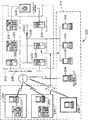
図6は、図5に示した方法を実行するために使用して、例えばパルスデトネーションシステムを含むガスタービンエンジンの能率的かつ費用効果のある設計を可能にすることができるモデリングシステム210の別の実施形態の例示的なシステムブロックダイグラムである。システム210は、サーバ212と該サーバ212に接続された複数のデバイス214とを含む。1つの実施形態において、デバイス214は、ウェブブラウザを含むコンピュータであり、サーバ212は、インターネットを経由してデバイス214にアクセスすることができる。別の実施形態においては、デバイス214は、カストマ・デバイスのネットワーク用のサーバである。システム210は、大容量記憶装置(図示せず)に接続される。例示的な実施形態において、サーバ212は、集中データベース218に接続されたデータベース・サーバ216を含む。
FIG. 6 shows another
デバイス214は、ローカルエリアネットワーク(LAN)又は広域ネットワーク(WAN)のようなネットワーク経由、ダイアルイン接続経由、ケーブルモデム、及び特別高速ISDNラインを含む多くのインタフェースを経由してインターネットに相互接続される。或いは、デバイス214は、インターネット電話又はその他のウェブベースの接続可能設備を含む、インターネットに相互接続できるあらゆるデバイスとすることができる。複数のプラントに関する情報を提供するデータベースが、サーバ212に格納され、デバイス214の1つにおいてユーザは、該デバイス214の1つを経由してサーバ212にログオンすることによってこのデータベースにアクセスすることができる。
システム210は、種々のユーザインタフェースを提供し、それによってユーザが、複数のプラントにおいて監視されている装置からの作動データにアクセスできるように構成される。サーバ212は、クライアントシステム214からダウンロードの要求を受信したときに、格納された情報にアクセスし、クライアントシステムの少なくとも1つに要求された作動データをダウンロードする。データベースは、標準ウェブブラウザで構成されたクライアントシステム214を用いてユーザによりアクセスされる。
図7は、ガスタービンエンジンのモデリングシステム210に使用することができるサーバアーキテクチュアの拡張バージョンのブロック図である。システム210は、サーバ・サブシステム212とユーザデバイス214とを含む。サーバ・サブシステム212は、データベース・サーバ216と、アプリケーション・サーバ224と、ウェブ・サーバ226と、ファックス・サーバ228と、ディレクトリ・サーバ230と、メール・サーバ232とを含む。ディスク記憶装置234は、データベース・サーバ216とディレクトリ・サーバ230とに接続される。サーバ216、224、226、228、230及び232は、ローカルエリアネットワーク(LAN)236内で接続される。加えて、システム管理ワークステーション238、ユーザワークステーション240、及び監視ワークステーション242が、LAN236に接続される。或いは、ワークステーション238、240、及び242は、インターネットリンクを介してLAN236に接続されるか、又はイントラネットを経由して接続される。
FIG. 7 is a block diagram of an expanded version of a server architecture that can be used in the gas turbine
各ワークステーション238、240、及び242は、ウェブブラウザを有するパーソナルコンピュータである。ワークステーションで通常実行される機能は、典型的には、それぞれのワークステーション238、240、及び242で実行されるものとして図示されているが、このような機能は、LAN236に接続された多くのパーソナルコンピュータの1つで実行されることができる。ワークステーション238、240、及び242は、LAN236にアクセスする個人によって実行されることができる、異なった形式の機能を理解するのを容易にするために、個別の機能のみと組み合わされたものとして図示されている。
Each
他の実施形態において、サーバ・サブシステム212は、ISPインターネット接続248を介して、種々の個人又は従業員244に、或いはユーザ246に通信可能に接続されるように構成される。例示的な実施形態における通信は、インターネットを介して行われるものとして図示されているが、他の実施形態においては、あらゆる他の広域ネットワーク(WAN)型通信を利用することができ、すなわち該システム及び方法は、インターネットを介して実行されるものに限定されるものではない。加えて、WAN250でなくて、ローカルエリアネットワーク236を、WANの代りに使用することができる。
In other embodiments,
例示的な実施形態において、ワークステーション252を有する、許可された個人或いは企業体の従業員は、サーバ・サブシステム212にアクセスすることができる。ユーザデバイス214の1つは、離れた場所に設置された上級管理者のワークステーション254を含む。ワークステーション252及び254は、ウェブブラウザを有するパーソナルコンピュータである。また、ワークステーション252及び254は、サーバ・サブシステム212と通信するように構成されている。更に、ファックス・サーバ228は、電話リンクを介して、企業体の外に位置する従業員と、またユーザシステム256を含む、離れた場所に設置されたユーザシステムの何れもと通信する。ファックス・サーバ228は、他のワークステーション238、240、及び242とも同様に通信するように構成されている。
In the exemplary embodiment, an authorized individual or corporate employee having a
上述のモデリングシステムは、パルスデトネーションシステムを含むガスタービンエンジンについての性能及び設計特性を予測することを可能にする。より具体的には、モデリングシステムは、サイクル・デザイン及びオフ・デザイン性能マッピングの両方についての性能及び設計特性を予測する。その結果、上述のモデリングシステムは、パルスデトネーションシステムを含むガスタービンエンジンの能率的かつ費用効果のある設計を可能にする。 The modeling system described above makes it possible to predict performance and design characteristics for a gas turbine engine that includes a pulse detonation system. More specifically, the modeling system predicts performance and design characteristics for both cycle design and off-design performance mapping. As a result, the modeling system described above enables an efficient and cost-effective design of a gas turbine engine that includes a pulse detonation system.
モデリングシステムの例示的な実施形態を、上に詳細に説明した。このシステムは、本明細書に記載した特定の実施形態に限定されるものではなく、むしろ各システムの構成要素は、本明細書に記載した他の構成要素から独立して個別に利用されることができる。各モデリングシステムの構成要素はまた、モデリングシステムの構成要素と組み合わせて使用することができる。 Exemplary embodiments of modeling systems have been described in detail above. This system is not limited to the specific embodiments described herein, but rather the components of each system are used separately and independently of the other components described herein. Can do. Each modeling system component can also be used in combination with a modeling system component.
様々な特定の実施形態に関して本発明を説明したが、本発明が特許請求の範囲の技術思想及び技術的範囲内の変更で実施することができることは、当業者には明らかであろう。なお、特許請求の範囲に記載された符号は、理解容易のためであってなんら発明の技術的範囲を実施例に限縮するものではない。 While the invention has been described in terms of various specific embodiments, those skilled in the art will recognize that the invention can be practiced with modification within the spirit and scope of the claims. In addition, the code | symbol described in the claim is for easy understanding, and does not limit the technical scope of an invention to an Example at all.
100 モデリングシステム
102 コンピュータ
104 データベース
106 デトネーションプログラム
108 デトネーション・フィルタイム・プログラム
110 チューブ寸法決定プログラム
112 エジェクタ・プログラム
114 ファン・タービン・インタフェース・プログラム
116 エンジンシステム性能プログラム
118 エンジン・ノズル・インタフェース・プログラム
DESCRIPTION OF
Claims (5)
プロセッサを含むコンピュータ(102)と、
前記コンピュータに接続された少なくとも1つのデータベース(104)と、
を含み、前記プロセッサが、
前記パルスデトネーションシステムの特性を、
データベース(104)内部に格納されたエンジンパラメータ・データを使用して、エンジン(10)のパルス作動の間にデトネーションチューブ(60)及びデトネーションチャンバ(64)内部に発生するデトネーションの開始の瞬間及び位置からの時間及び空間における、温度及び圧力の履歴を計算し(158)、
デトネーションチューブ(60)及びデトネーションチャンバ(64)内部の各パルスについて、パルスのデトネーションと、デトネーションチューブ(60)内部の圧力の、デトネーション前にデトネーションチューブ(60)内部に存在した圧力への復帰との間に経過した第1の時間の長さを計算し(160)、
データベース(104)内部に格納されたガスの熱力学的データを用いて、各パルスについて、デトネーションに先だって燃料及び空気がデトネーションチューブ(60)を満たすのに必要な第2の時間の長さを計算し(162)、
前記第1及び第2の時間の長さから、デトネーションチューブ(60)の所望の寸法を求める(164)
ことによって予測し(170)、
エンジンのサイクル・デザイン及びオフ・デザイン性能特性マッピングのために、前記パルスデトネーションシステムの前記予測された第1及び第2の時間の長さ並びにデトネーションチューブ(60)の寸法を用いて、前記ガスタービンエンジンの特性を予測する(172)、
ようにプログラムされている、
ことを特徴とするモデリングシステム(100)。 A modeling system (100) used to model a gas turbine engine (10) comprising a pulse detonation system (50) comprising a detonation tube (60) and a detonation chamber (64) ,
A computer (102) including a processor;
At least one database (104) connected to the computer;
The processor includes:
The characteristics of the pulse detonation system,
Using the engine parameter data stored inside the database (104), the instant and position of the start of detonation that occurs inside the detonation tube (60) and the detonation chamber (64) during pulsing of the engine (10) Calculate temperature and pressure history in time and space from (158);
For each pulse inside the detonation tube (60) and the detonation chamber (64), the pulse detonation and the return of the pressure inside the detonation tube (60) to the pressure existing inside the detonation tube (60) before detonation. Calculate the length of the first time passed in between (160),
Using the gas thermodynamic data stored in the database (104), for each pulse, calculate the second length of time required for the fuel and air to fill the detonation tube (60) prior to detonation. (162),
A desired dimension of the detonation tube (60) is determined from the length of the first and second times (164).
Predicted by (170),
Using the predicted first and second lengths of time and the dimensions of the detonation tube (60) of the pulse detonation system for engine cycle design and off-design performance characteristic mapping, the gas turbine Predict engine characteristics (172),
Is programmed to,
A modeling system (100) characterized by that.
Applications Claiming Priority (1)
| Application Number | Priority Date | Filing Date | Title |
|---|---|---|---|
| US10/342,931 US7200538B2 (en) | 2003-01-15 | 2003-01-15 | Methods and apparatus for modeling gas turbine engines |
Publications (3)
| Publication Number | Publication Date |
|---|---|
| JP2004220614A JP2004220614A (en) | 2004-08-05 |
| JP2004220614A5 JP2004220614A5 (en) | 2007-03-01 |
| JP4619008B2 true JP4619008B2 (en) | 2011-01-26 |
Family
ID=32655469
Family Applications (1)
| Application Number | Title | Priority Date | Filing Date |
|---|---|---|---|
| JP2004006361A Expired - Fee Related JP4619008B2 (en) | 2003-01-15 | 2004-01-14 | Method and apparatus for modeling a gas turbine engine |
Country Status (4)
| Country | Link |
|---|---|
| US (1) | US7200538B2 (en) |
| EP (1) | EP1445464B1 (en) |
| JP (1) | JP4619008B2 (en) |
| CN (1) | CN100487712C (en) |
Families Citing this family (13)
| Publication number | Priority date | Publication date | Assignee | Title |
|---|---|---|---|---|
| US7610179B2 (en) * | 2004-09-24 | 2009-10-27 | United Technologies Corporation | Coupled parametric design of flow control and duct shape |
| CN101303702B (en) * | 2007-05-09 | 2011-07-06 | 通用汽车环球科技运作公司 | Rapid bench examination and modeling method for engine |
| US7681440B2 (en) * | 2007-10-31 | 2010-03-23 | Pratt & Whitney Canada Corp. | Method and apparatus for turbine engine dynamic characterization |
| US8457936B2 (en) * | 2008-11-24 | 2013-06-04 | Honeywell International Inc. | Apparatus and methods for simulating a system steady state devoid of performing full transient operating conditions |
| FR2939509B1 (en) * | 2008-12-09 | 2011-03-04 | Snecma | METHOD AND SYSTEM FOR ESTIMATING A VEIN TEMPERATURE IN A TURBOKIN. |
| FR2939508B1 (en) * | 2008-12-09 | 2011-01-07 | Snecma | METHOD AND SYSTEM FOR CORRECTING MEASUREMENT SIGNAL OF TEMPERATURE. |
| US20110047962A1 (en) * | 2009-08-28 | 2011-03-03 | General Electric Company | Pulse detonation combustor configuration for deflagration to detonation transition enhancement |
| GB0921660D0 (en) * | 2009-12-10 | 2010-01-27 | Zettner Michael | Method for increasing the efficiency of a heat exchanger |
| CN101806260B (en) * | 2010-03-04 | 2012-01-11 | 西北工业大学 | Multitube parallel pulse detonation combustion chamber and ignition detonation method thereof |
| US9140456B2 (en) * | 2011-12-01 | 2015-09-22 | General Electric Company | Variable initiation location system for pulse detonation combustor |
| US9718562B1 (en) * | 2016-01-29 | 2017-08-01 | General Electric Company | System and method of evaluating the effect of dust on aircraft engines |
| WO2017194240A1 (en) * | 2016-05-13 | 2017-11-16 | Siemens Aktiengesellschaft | Method and system for determining state variables of an operating fluid |
| CN107945615A (en) * | 2017-12-08 | 2018-04-20 | 中国航空工业集团公司成都飞机设计研究所 | A kind of method of real-time analog simulation engine |
Family Cites Families (28)
| Publication number | Priority date | Publication date | Assignee | Title |
|---|---|---|---|---|
| US2635420A (en) * | 1947-05-14 | 1953-04-21 | Shell Dev | Jet propulsion engine with auxiliary pulse jet engine |
| DE2046079B1 (en) | 1970-09-18 | 1971-12-23 | Messerschmitt Bolkow Blohm GmbH, 8000 München | AIR BREATHING SPRAY PIPE |
| US4215412A (en) * | 1978-07-13 | 1980-07-29 | The Boeing Company | Real time performance monitoring of gas turbine engines |
| ES8800981A1 (en) | 1985-06-28 | 1987-12-01 | Univ Minnesota | Process and composition for treatment of cancer and non-malignant tumors. |
| GB8927377D0 (en) * | 1989-12-04 | 1990-01-31 | Univ Edinburgh | Improvements in and relating to amperometric assays |
| US5694768A (en) * | 1990-02-23 | 1997-12-09 | General Electric Company | Variable cycle turbofan-ramjet engine |
| US5080496A (en) * | 1990-06-25 | 1992-01-14 | General Electric Company | Method and apparatus for compensated temperature prediction |
| US5280756A (en) * | 1992-02-04 | 1994-01-25 | Stone & Webster Engineering Corp. | NOx Emissions advisor and automation system |
| US5402333A (en) * | 1992-06-15 | 1995-03-28 | E. I. Du Pont De Nemours & Co., Inc. | System and method for improving model product property estimates |
| JP3196390B2 (en) * | 1992-12-25 | 2001-08-06 | 富士電機株式会社 | Parameter identifier |
| US5345758A (en) | 1993-04-14 | 1994-09-13 | Adroit Systems, Inc. | Rotary valve multiple combustor pulse detonation engine |
| US5873240A (en) * | 1993-04-14 | 1999-02-23 | Adroit Systems, Inc. | Pulsed detonation rocket engine |
| US5726891A (en) * | 1994-01-26 | 1998-03-10 | Sisson; Patterson B. | Surge detection system using engine signature |
| US5689066A (en) * | 1995-08-15 | 1997-11-18 | Stevenson; Dennis B. | Method and apparatus for analyzing gas turbine pneumatic fuel system |
| GB2321720A (en) | 1997-02-04 | 1998-08-05 | Secr Defence | Modelling a system with more parameters than sensors |
| US5983624A (en) * | 1997-04-21 | 1999-11-16 | Anderson; J. Hilbert | Power plant having a U-shaped combustion chamber with first and second reflecting surfaces |
| US7020595B1 (en) * | 1999-11-26 | 2006-03-28 | General Electric Company | Methods and apparatus for model based diagnostics |
| US6442930B1 (en) * | 2000-03-31 | 2002-09-03 | General Electric Company | Combined cycle pulse detonation turbine engine |
| US6477829B1 (en) * | 2000-05-09 | 2002-11-12 | Lockheed Martin Corporation | Combined cycle pulse combustion/gas turbine engine |
| US6582183B2 (en) * | 2000-06-30 | 2003-06-24 | United Technologies Corporation | Method and system of flutter control for rotary compression systems |
| GB0027288D0 (en) * | 2000-11-08 | 2000-12-27 | Rolls Royce Plc | Overthrust protection system and method |
| US6505462B2 (en) * | 2001-03-29 | 2003-01-14 | General Electric Company | Rotary valve for pulse detonation engines |
| US6457938B1 (en) * | 2001-03-30 | 2002-10-01 | General Electric Company | Wide angle guide vane |
| US20020177985A1 (en) * | 2001-04-23 | 2002-11-28 | Kraft Joseph Anthony | Computer system and method for radial cooled bucket optimization |
| KR20030053596A (en) * | 2001-12-22 | 2003-07-02 | 남궁영 | Piston compressed turbine engine and its control method |
| US7296411B2 (en) * | 2002-06-21 | 2007-11-20 | Darko Segota | Method and system for regulating internal fluid flow within an enclosed or semi-enclosed environment |
| US6782703B2 (en) * | 2002-09-11 | 2004-08-31 | Siemens Westinghouse Power Corporation | Apparatus for starting a combined cycle power plant |
| US6796123B2 (en) * | 2002-11-01 | 2004-09-28 | George Lasker | Uncoupled, thermal-compressor, gas-turbine engine |
-
2003
- 2003-01-15 US US10/342,931 patent/US7200538B2/en not_active Expired - Fee Related
-
2004
- 2004-01-09 EP EP04250085.0A patent/EP1445464B1/en not_active Expired - Fee Related
- 2004-01-14 JP JP2004006361A patent/JP4619008B2/en not_active Expired - Fee Related
- 2004-01-15 CN CNB2004100067046A patent/CN100487712C/en not_active Expired - Fee Related
Also Published As
| Publication number | Publication date |
|---|---|
| US20060282242A1 (en) | 2006-12-14 |
| US7200538B2 (en) | 2007-04-03 |
| EP1445464B1 (en) | 2016-03-23 |
| EP1445464A1 (en) | 2004-08-11 |
| CN100487712C (en) | 2009-05-13 |
| JP2004220614A (en) | 2004-08-05 |
| CN1538341A (en) | 2004-10-20 |
Similar Documents
| Publication | Publication Date | Title |
|---|---|---|
| JP4619008B2 (en) | Method and apparatus for modeling a gas turbine engine | |
| Sousa et al. | Thermodynamic analysis of a gas turbine engine with a rotating detonation combustor | |
| Wu et al. | System performance and thermodynamic cycle analysis of airbreathing pulse detonation engines | |
| US10371002B2 (en) | Control system for a gas turbine engine | |
| US10436110B2 (en) | Rotating detonation engine upstream wave arrestor | |
| EP3450700A1 (en) | Vibration control for a gas turbine engine | |
| Kyprianidis | An approach to multi-disciplinary aero engine conceptual design | |
| Ebrahimi et al. | Numerical simulation of a pulse detonation engine with hydrogen fuels | |
| Petters et al. | Engine system performance of pulse detonation concepts using the NPSS program | |
| Adolfo et al. | Thermodynamic Analysis of an Aircraft Engine to estimate performance and emissions at LTO cycle | |
| Yarlagadda | Performance analysis of J85 turbojet engine matching thrust with reduced inlet pressure to the compressor | |
| Niazi et al. | Development and Application of a CFD Solver to the Simulation of Centrifugal Compressors | |
| Eidelman et al. | Pulsed detonation engine: Key issues | |
| Smith et al. | Numerical simulation of enhanced mixing in jet plumes using pulsed blowing | |
| Davis Jr | A Post-Stall Compression System Modeling Technique | |
| Mitani et al. | Flow choking by drag and combustion in supersonic engine testing | |
| Nickl et al. | Performance Modeling of a Composite Cycle Engine With Rotary Engine | |
| Greatrix et al. | Gas turbine engines: Fundamentals | |
| Nae et al. | Mathematical modeling and numerical simulations for performance prediction in case of the Turbojet engine | |
| CN108256275B (en) | Numerical simulation ignition detonation method for rotary detonation engine | |
| Debiasi et al. | Cycle analysis for quieter supersonic turbofan engines | |
| Xiao et al. | Pulse Detonation Engine Performance Analysis | |
| Whellens et al. | Genetic algorithm based optimisation of intercooled recuperated turbofan design | |
| Yadav et al. | Aero-thermodynamic model for digital simulation of turbofan engine | |
| Kumar | Parametric And Performance Analysis Of A Hybrid Pulse Detonation/Turbofan Engine |
Legal Events
| Date | Code | Title | Description |
|---|---|---|---|
| A521 | Request for written amendment filed |
Free format text: JAPANESE INTERMEDIATE CODE: A523 Effective date: 20070111 |
|
| A621 | Written request for application examination |
Free format text: JAPANESE INTERMEDIATE CODE: A621 Effective date: 20070111 |
|
| A131 | Notification of reasons for refusal |
Free format text: JAPANESE INTERMEDIATE CODE: A131 Effective date: 20100126 |
|
| A601 | Written request for extension of time |
Free format text: JAPANESE INTERMEDIATE CODE: A601 Effective date: 20100422 |
|
| RD02 | Notification of acceptance of power of attorney |
Free format text: JAPANESE INTERMEDIATE CODE: A7422 Effective date: 20100422 |
|
| RD04 | Notification of resignation of power of attorney |
Free format text: JAPANESE INTERMEDIATE CODE: A7424 Effective date: 20100422 |
|
| A602 | Written permission of extension of time |
Free format text: JAPANESE INTERMEDIATE CODE: A602 Effective date: 20100427 |
|
| A521 | Request for written amendment filed |
Free format text: JAPANESE INTERMEDIATE CODE: A523 Effective date: 20100723 |
|
| TRDD | Decision of grant or rejection written | ||
| A01 | Written decision to grant a patent or to grant a registration (utility model) |
Free format text: JAPANESE INTERMEDIATE CODE: A01 Effective date: 20101005 |
|
| A01 | Written decision to grant a patent or to grant a registration (utility model) |
Free format text: JAPANESE INTERMEDIATE CODE: A01 |
|
| A61 | First payment of annual fees (during grant procedure) |
Free format text: JAPANESE INTERMEDIATE CODE: A61 Effective date: 20101026 |
|
| FPAY | Renewal fee payment (event date is renewal date of database) |
Free format text: PAYMENT UNTIL: 20131105 Year of fee payment: 3 |
|
| R150 | Certificate of patent or registration of utility model |
Free format text: JAPANESE INTERMEDIATE CODE: R150 |
|
| R250 | Receipt of annual fees |
Free format text: JAPANESE INTERMEDIATE CODE: R250 |
|
| R250 | Receipt of annual fees |
Free format text: JAPANESE INTERMEDIATE CODE: R250 |
|
| LAPS | Cancellation because of no payment of annual fees |