JP4613397B2 - Image recognition apparatus, image recognition method, and computer-readable recording medium on which image recognition program is recorded - Google Patents
Image recognition apparatus, image recognition method, and computer-readable recording medium on which image recognition program is recorded Download PDFInfo
- Publication number
- JP4613397B2 JP4613397B2 JP2000195146A JP2000195146A JP4613397B2 JP 4613397 B2 JP4613397 B2 JP 4613397B2 JP 2000195146 A JP2000195146 A JP 2000195146A JP 2000195146 A JP2000195146 A JP 2000195146A JP 4613397 B2 JP4613397 B2 JP 4613397B2
- Authority
- JP
- Japan
- Prior art keywords
- character
- image
- character image
- continuity
- data
- Prior art date
- Legal status (The legal status is an assumption and is not a legal conclusion. Google has not performed a legal analysis and makes no representation as to the accuracy of the status listed.)
- Expired - Fee Related
Links
Images


Classifications
-
- G—PHYSICS
- G06—COMPUTING; CALCULATING OR COUNTING
- G06V—IMAGE OR VIDEO RECOGNITION OR UNDERSTANDING
- G06V30/00—Character recognition; Recognising digital ink; Document-oriented image-based pattern recognition
- G06V30/40—Document-oriented image-based pattern recognition
- G06V30/41—Analysis of document content
- G06V30/413—Classification of content, e.g. text, photographs or tables
Landscapes
- Engineering & Computer Science (AREA)
- Computer Vision & Pattern Recognition (AREA)
- Artificial Intelligence (AREA)
- Physics & Mathematics (AREA)
- General Physics & Mathematics (AREA)
- Multimedia (AREA)
- Theoretical Computer Science (AREA)
- Character Discrimination (AREA)
- Character Input (AREA)
Description
【0001】
【発明の属する技術分野】
本発明は、画像認識技術に関し、特に、入力された画像データ中の文字画像を、文字コードデータに変換するか否かを判定する処理についての画像認識技術に関する。
【0002】
【従来の技術】
最近の画像認識装置は、読取に関する条件の良い原稿(例えば同一フォントの文字のみで構成された原稿)であれば、極めて高い精度で文字画像を文字コードとして認識可能である。しかしながら、原稿上の文字の品質が悪かったり、原稿上の文字等のレイアウトが複雑であると、文字画像を文字コードとして認識する認識精度が大きく低下し、誤認識される文字画像が増加してしまう。
【0003】
このような問題に対し、原稿を読み取って得られた画像データのすべてをバックアップ用に保存するシステムが知られている。しかし、バックアップ用の画像データを含んで保存されたファイルの容量は、当然ながら入力された画像データよりも大幅に増えてしまう。
【0004】
そこで、誤認識されている可能性が高い文字画像のみを、文字コードデータに変換することなく、文字画像データ(例えばビットマップ形式の画像データ)のまま出力する画像認識装置が提案されている。ここで、誤認識の可能性の判断には、例えばあらかじめ記憶されている標準パターンとの類似度などの結果から検出された、文字コードを認識する確からしさの情報が使用される。
【0005】
【発明が解決しようとする課題】
しかしながら、文字コードを認識する確からしさの情報だけでは、画像データ中の文字画像のうち、どの文字画像が正確に文字コードとして認識されていて、どの文字画像が誤認識されているかという判別の精度はあまり高いものではなく、結果的に誤認識される文字画像を十分に除去することが困難である。
【0006】
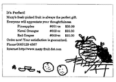
特に、最近では、読み取られる原稿は多様化しており、カラーの原稿や複雑なレイアウトの原稿などが増えている。これに伴って、画像データから文字画像が存在する文字領域を抽出することが難しくなってきている。したがって、例えば、図11に示すような、非文字である図形が文字部の中に埋め込まれた原稿を読み取る場合、図12に示すように、得られた画像データ中の非文字画像である図形画像から誤って文字コードを認識して、文字コードデータで出力される事態が生じ得る。なお、図中の符号E1 は、図形画像から文字コードが誤認識されて得られた文字コードデータ、符号E2 は、文字画像から文字コードが誤認識されて得られた文字コードデータを示す。しかも、図形画像から文字コードデータE1 に変換される際の文字コードを認識する確からしさが、本来の文字画像とあまり変わらない場合がある。このため、文字コードを認識する確からしさの情報だけで文字コードデータに変換するか否かの判定を行うと、図形画像から誤認識されて得られた文字コードデータを除去することができない。
【0007】
一方、特開平8−55185号公報には、画像データ中の文字画像が存在する文字領域を抽出する段階で、近隣の文字画像との位置関係を調べながら文字領域を抽出するという技術が提案されている。また、特開平8−161421号公報には、文字領域を抽出する段階で、近隣の文字画像との位置関係を調べて文字領域の候補となる文字候補領域をまず抽出し、この文字候補領域内の画像データのうち文字コードを認識することができる文字画像によって文字領域を再構成するという技術が提案されている。しかしながら、上記公報に開示されたいずれの技術も、画像データ中から文字領域を抽出するための技術に過ぎない。
【0008】
本発明は、上記従来技術の問題点に鑑みてなされたものであり、本発明の目的は、入力された画像データ中の文字画像が文字コードデータに変換される割合を高くしつつ、誤認識の文字コードデータが出力されることを有効に防止することにある。
【0009】
【課題を解決するための手段】
本発明の目的は、下記する手段により達成される。
【0010】
(1) 画像認識装置において、入力された画像データ中の文字画像から文字コードを認識する文字認識部と、文字コードが認識された文字画像についての、近隣の文字画像との連続性の度合いである文字連続性度を検出する文字連続性度検出部と、文字コードが認識された文字画像についての文字連続性度の、第1の閾値及びそれよりも小さい第2の閾値との大小関係を判定する出力形式判定部と、を有し、文字連続性度が第1の閾値よりも大きいと判定された文字画像を文字コードデータに変換し、文字連続性が第2の閾値よりも大きく第1の閾値よりも小さいと判定された文字画像を切り出して、隣接する文字コードデータに重なることなく連続して配置される文字画像データを作成することを特徴とする画像認識装置。
【0011】
(2) 前記文字連続性度検出部は、文字コードが認識された文字画像と該文字画像の近隣の文字画像との距離、文字コードが認識された文字画像と該文字画像の近隣の文字画像とのフォントサイズの差、文字コードが認識された文字画像と該文字画像の近隣の文字画像とのフォントのタイプの相違、文字コードが認識された文字画像が含まれる連続した文字画像の列の長さ、および文字コードが認識された文字画像と該文字画像の近隣の文字画像との色の差のうち、少なくともいずれか一つ以上を検出することを特徴とする上記(1)に記載の画像認識装置。
【0014】
(3) 電子ファイルを作成するファイル作成部、をさらに有することを特徴とする上記(1)または(2)に記載の画像認識装置。
【0015】
(4) 原稿を読み取ることによって画像データを得るスキャナ部、をさらに有することを特徴とする上記(1)〜(3)のいずれかに記載の画像認識装置。
【0016】
(5) 画像データを受信する画像データ受信部と、データを用紙に印刷するプリント部と、をさらに有することを特徴とする上記(1)〜(4)のいずれかに記載の画像認識装置。
【0017】
(6) 画像認識方法において、入力された画像データ中の文字画像から文字コードを認識する過程と、文字コードが認識された文字画像についての、近隣の文字画像との連続性の度合いである文字連続性度を検出する過程と、文字コードが認識された文字画像についての文字連続性度の、第1の閾値及びそれよりも小さい第2の閾値との大小関係を判定する過程と、文字連続性度が第1の閾値よりも大きいと判定された文字画像を文字コードデータに変換し、文字連続性が第2の閾値よりも大きく第1の閾値よりも小さいと判定された文字画像を切り出して、隣接する文字コードデータに重なることなく連続して配置される文字画像データを作成する過程と、を有することを特徴とする画像認識方法。
【0018】
(7) 画像認識プログラムを記録したコンピュータ読取可能な記録媒体であって、入力された画像データ中の文字画像から文字コードを認識する過程と、文字コードが認識された文字画像についての、近隣の文字画像との連続性の度合いである文字連続性度を検出する過程と、文字コードが認識された文字画像についての文字連続性度の、第1の閾値及びそれよりも小さい第2の閾値との大小関係を判定する過程と、文字連続性度が第1の閾値よりも大きいと判定された文字画像を文字コードデータに変換し、文字連続性が第2の閾値よりも大きく第1の閾値よりも小さいと判定された文字画像を切り出して、隣接する文字コードデータに重なることなく連続して配置される文字画像データを作成する過程と、をコンピュータに実行させるための画像認識プログラムを記録したコンピュータ読取可能な記録媒体。
【0019】
【発明の実施の形態】
以下、添付した図面を参照して、本発明の実施形態を説明する。
【0020】
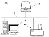
図1は、本発明の第1実施形態に係る画像認識装置を含む情報機器システムの構成図である。
【0021】
情報機器システム100は、画像認識装置としての機能を有するコンピュータ10、画像入力装置であるスキャナ50、および、画像出力装置であるプリンタ60等の情報機器がネットワークN上に接続されて構成されている。
【0022】
コンピュータ10、スキャナ50、および、プリンタ60は、ネットワークNを経由して互いにデータの授受を行うことができる。
【0023】
図2は、コンピュータ10の概略構成を示すブロック図である。
【0024】
コンピュータ10は、各情報機器との間でデータの授受を行うためのインターフェース(I/F)18と、スキャナ50を制御するためのスキャナドライバ12と、プリンタ60を制御するためのプリンタドライバ14と、所定のプログラムやデータを記憶するROM15と、一時的にデータを記憶するRAM16と、各種情報の表示やユーザからの指示入力が可能な操作パネル17と、文字認識等の処理を行う画像処理部13(詳細後述)と、上記各部を制御する主制御部11とを有している。なお、スキャナドライバ12、プリンタドライバ14は、ソフトウェアであり、図示しないハードディスク等の記憶装置に記憶されている。
【0025】
図1に示す情報機器システムの動作指示は、コンピュータ10の操作パネル17から行うことができる。本実施形態において操作パネル17は、コンピュータ10のディスプレイ上に表示される架空のパネルであり、コンピュータ10を操作するためのキーボードやマウス等の機器により、動作指示を行う。
【0026】
例えば、操作パネル17上にはスキャン&ファイルボタンとスキャン&プリントボタンとが表示されており、スキャン&ファイルボタンで動作指示を行った場合には、スキャナ50は原稿読取動作を開始し、読み取りによって得られた画像データはコンピュータ10に送信され、画像処理部13にて文字認識等の画像処理がなされた後、所定の形式のファイルとしてコンピュータ10内の記憶装置に保存される。
【0027】
また、スキャン&プリントボタンで動作指示を行った場合には、スキャナ50の読み取りによって得られた画像データは、画像処理部13にて文字認識等の画像処理がなされた後、プリンタ60に送信され用紙上に印刷される。
【0028】
次に、画像処理部13について詳細に説明する。
【0029】
画像処理部13は、文字認識部31、文字色検出部32、出力形式判定部33、文字画像データ作成部34、文字消去部35、およびファイル作成部36を備えている。
【0030】
文字認識部31は、個々の文字画像から文字コードを認識して文字コードデータを得るほか、文字コードを認識する確からしさの度合いである文字認識確度を検出する。文字画像から文字コードを認識する方法は、例えば、各文字画像の特徴量とあらかじめ記憶されている辞書パターンとの一致の度合いに基づいて行われる。文字認識確度は、例えば10段階で与えられ、値が大きいと文字認識確度が高いことを意味する。また、文字認識部31は、文字画像の位置情報を認識する。個々の文字画像の位置情報は、例えば図3に示すように、画像データの左上を原点として、各文字画像の外接矩形の左上および右下の座標として得られる。
さらに、文字認識部31は、文字画像から、フォントのタイプやフォントサイズ、さらには太字・斜体などのスタイル、アンダーライン等の文字属性を認識する。
【0031】
フォントのタイプは、例えばセリフ系とサンセリフ系などに分類されて判別される。また、フォントサイズは、個々の文字画像の外接矩形の大きさと、文字コードが認識されて得られた文字コードデータを一般的なフォントで表した場合の大きさとを比較することにより求められる。所定の代表的なフォントの文字高さや文字幅などの情報、すなわちフォントメトリックデータは、あらかじめデータとして記憶されている。
【0032】
文字色検出部32は、文字コードが認識された個々の文字画像の色を検出する。
【0033】
出力形式判定部33は、文字コードが認識された文字画像を、文字コードデータに変換するか否かの判定を行う。本実施形態では、出力形式判定部33は、文字コードが認識された文字画像を調べて、文字コードデータに変換するか、文字コードデータに変換せずに、入力された画像データ中の文字画像が切り出されて形成され、隣接する文字コードデータに重なることなく連続して配置される文字画像データを作成するか、あるいは入力された画像データのまま元の位置に残すか、の判定を行う。そして、文字画像データ作成部34は、文字コードが認識された文字画像のうち、文字画像データを作成する旨の判定が行われた文字画像を、入力された画像データから切り出して文字画像データを作成する。
【0034】
文字消去部35は、元の画像データ、すなわち入力されたカラーの画像データから、文字コードデータまたは文字画像データとされた後の元の文字画像を消去する。
【0035】
ファイル作成部36は、入力された画像データ中の文字画像から得られた文字コードデータや文字画像データなどを用いて、所定の形式のファイルを作成する。
【0036】
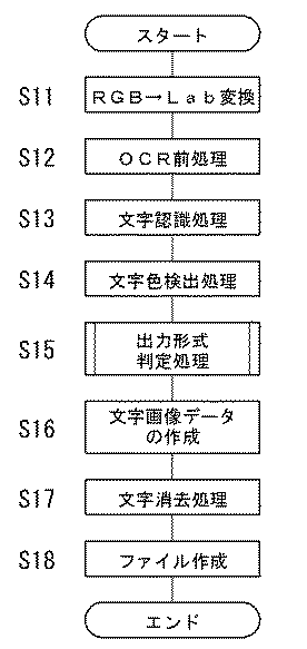
次に、画像処理部13の動作を図4および図5のフローチャートを用いて説明する。
【0037】
まず、スキャナ50で原稿を読み取ることによって得られた画像データに対し、RGB表色系からLab表色系へと色空間の変換を行う(S11)。Lab表色系は、スキャナあるいはプリンタ等の個々の情報機器に依存しないので、ネットワークN上で共通の色情報として扱うことができるものである。
【0038】
次に、文字認識部31に入力する画像データを作成するために、OCR前処理が行われる(S12)。後に文字認識部31がモノクロ2値画像データから特徴量を抽出して文字コードの認識を行うことから、OCR前処理では、まず、Lab表色系で表示されたカラー画像データに対して2値化処理を行うことにより、文字画像が黒で、その背景画像が白のモノクロ2値画像データを作成する。本実施形態では、文字画像およびその背景画像のL、a、bのレベルを検出することにより、例えば白地に書かれた色文字や、色地に書かれた黒文字等が原稿上に表されていても、原稿を読み取ることによって入力された画像データ中の文字画像から十分に文字コードを認識することができるように2値化処理を行う。この他、OCR前処理では、入力された画像データ中の孤立点等のノイズの除去、原稿が傾いて読み取られた場合の補正処理、つぶれたりかすれたりしている文字画像の補正なども行われる。
【0039】
OCR前処理により得られたモノクロ2値画像データは、文字認識部31に入力され、文字認識処理が行われる(S13)。文字認識部31は、モノクロ2値画像データから文字画像が存在する文字領域の抽出を行った後、文字領域内の個々の文字画像から文字コードを認識する。また、文字認識部31は、文字コードを認識する確からしさの度合いである文字認識確度を検出することができ、さらに、文字画像の位置情報のほか、フォントのタイプ、フォントサイズ、太字・斜体などのスタイル、アンダーライン等の文字属性を認識する。
【0040】
次いで、文字色検出処理が行われる(S14)。すなわち、文字コードが認識された個々の文字画像の色は、文字色検出部32により検出される。ここでは、Lab表色系に色変換された画像データが使用される。文字画像の色の検出は、例えば、画像データ中の文字画像が存在する文字領域のLabの値を読み取り、文字画像を構成する全画素について、L、a、bそれぞれの平均値を求めることにより行う。文字画像とその背景画像との画素の区別は、OCR前処理(S12)で得られたモノクロ2値画像データを用いて行う。つまり、個々の文字画像の外接矩形内において、モノクロ2値画像データにおける黒画素を文字画像の画素、白画素を背景画像の画素と区別することができる。
【0041】
文字画像を文字コードデータに変換して出力する場合、文字色検出部32により検出された個々の文字画像の色情報に基づいて、色を指定して文字コードデータが出力される。これにより、例えば原稿上の文字の色を再現することができる。
【0042】
そして、文字領域内の個々の文字画像について出力形式の判定処理が行われる(S15)。すなわち、出力形式判定部33により、文字コードが認識された文字画像を、文字コードデータに変換するか否かの判定が行われる。
【0043】
出力形式判定部33は、大きく分けて2つの評価量に基づいて、出力形式の判定を行う。出力形式の判定を行うための第1の評価量は、文字コードを認識する確からしさの度合いである文字認識確度である。出力形式の判定を行うための第2の評価量は、文字コードが認識された文字画像についての、近隣の文字画像との連続性の度合いである文字連続性度である。この文字連続性度は、文字画像から認識される文字属性の連続性の面から、文字らしさを評価した値であり、その詳細は後述する。
【0044】
そして、出力形式判定部33は、文字コードが認識された文字画像のうち、文字コードデータに変換しないと判定した文字画像を、さらに2つの出力形式に分類して判定する。すなわち、出力形式判定部33は、文字コードが認識された文字画像が文字画像には違いないものの文字認識確度が小さい場合、隣接する文字コードデータに重なることなく連続して配置するために、入力された画像データ中の文字画像を切り出して文字画像データを作成すると判定する。また、出力形式判定部33は、文字コードが認識された文字画像が非文字画像である図形画像であるにもかかわらず誤って文字コードが認識されたと考えられる場合、当該文字画像を入力された画像データのまま元の位置に残すと判定する。
【0045】
次に、文字コードが認識された文字画像についての出力形式の判定処理についてさらに詳しく説明する。
【0046】
文字認識部31からは、個々の文字画像に対して、文字コードデータのほか、セリフ系・サンセリフ系などのフォントのタイプ、フォントサイズ、太字・斜体などのスタイル、アンダーライン等の文字属性、文字認識確度、文字コードが認識された各文字画像ごとの位置情報、などの情報が出力される。そして、これら文字認識部31からの情報をもとに、文字画像の位置や文字属性についての連続性を検出して文字らしさを評価する。前述したように、文字認識処理では、ある程度周辺の文字画像との位置関係を調べて、より文字らしい部分を文字領域として画像データから抽出するが、抽出された文字領域内に非文字画像である図形画像が文字画像と間違えられて含まれている場合がある。本実施形態では、特に、これらの孤立した文字画像を誤って文字コードデータに変換することのないように、すべての文字画像から文字コードを認識した後に、当該文字画像を文字コードデータに変換するか否かの判定を行うようにしている。
【0047】
文字連続性度、すなわち文字らしさの評価量は、文字コードが認識された文字画像と該文字画像の近隣の文字画像との距離、文字コードが認識された文字画像と該文字画像の近隣の文字画像とのフォントサイズの差、文字コードが認識された文字画像と該文字画像の近隣の文字画像とのフォントのタイプの相違、文字コードが認識された文字画像が含まれる連続した文字画像の列の長さ、および文字コードが認識された文字画像と該文字画像の近隣の文字画像との色の差、の5項目について順に調べ、各項目において文字画像の連続性に着目した評価ポイントを算出することにより検出される。
【0048】
具体的には、図5に示すように、まず、注目する個々の文字画像の順番を示す変数nを初期化する(S21)。
【0049】
そして、文字コードが認識された文字画像と該文字画像の近隣の文字画像との距離に基づいて、第1の評価ポイントを計算する(S22)。ここでは、注目文字画像の前後±k個の文字画像の位置情報(図3参照)が調べられ、次式により第1の評価ポイントP1nが計算される。なお、式中の添字は、個々の文字画像の順番を示す(以下の式において同様)。
【0050】
【数1】
但し、P1n<0のときは、P1n=0
M1 :第1の評価ポイントの最大値
X1 :文字コードが認識された文字画像の外接矩形の左X座標
X2 :文字コードが認識された文字画像の外接矩形の右X座標
Y1 :文字コードが認識された文字画像の外接矩形の上Y座標
Y2 :文字コードが認識された文字画像の外接矩形の下Y座標
である。
【0052】
上記式に示すように、近隣文字画像との距離が大きい程、第1の評価ポイントは小さくなる。すなわち、注目文字画像が近隣文字画像から離れている程、連続性が小さく、文字画像である可能性が低いということを表している。
【0053】
なお、上記式からわかるように、例えば複数の文字画像が横に並んで形成された行の右端や左端の文字画像を考慮するため、注目文字画像の右側の近隣文字画像との距離と左側の近隣文字画像との距離とを調べて、両者のうち小さい方が評価ポイントの計算に使用される。
【0054】
次に、文字コードが認識された文字画像と該文字画像の近隣の文字画像とのフォントサイズの差に基づいて、第2の評価ポイントを計算する(S23)。ここでは、注目文字画像の前後±k個の文字画像のフォントサイズが調べられ、次式により第2の評価ポイントP2nが計算される。
【0055】
【数2】
但し、P2n<0のときは、P2n=0
M1 :第2の評価ポイントの最大値
S :フォントサイズ
である。
【0057】
上記式の分母は、近隣文字画像の平均フォントサイズを表す。上記式に示すように、近隣文字画像とのフォントサイズの差が大きい程、連続性が小さく、第2の評価ポイントは小さくなる。
【0058】
次に、文字コードが認識された文字画像と該文字画像の近隣の文字画像とのフォントのタイプの相違に基づいて、第3の評価ポイントを計算する(S24)。
ここでは、注目文字画像の前後±k個の文字画像のフォントのタイプが調べられ、注目文字画像とフォントのタイプが相違している文字画像の数をNf として、次式により第3の評価ポイントP3nが計算される。
【0059】
P3n=M3 −Nf
但し、P3n<0のときは、P3n=0
M3 :第3の評価ポイントの最大値
である。
【0060】
上記式に示すように、近隣文字画像とのフォントのタイプの相違が多い程、連続性が小さく、第3の評価ポイントは小さくなる。
【0061】
次に、文字コードが認識された文字画像が含まれる連続した文字画像の列の長さに基づいて、第4の評価ポイントを計算する(S25)。ここでは、注目文字画像の前後に、順に個々の文字画像の外接矩形の間隔を調べ、当該間隔が所定の閾値TH以上であれば、文字画像列の区切りであると判断する。なお、閾値THは、例えば近隣文字画像の平均サイズによって変化させるのが望ましい。そして、注目文字画像をn番目の文字画像として、注目文字画像の左側に存在するi1 番目の文字画像から、注目文字画像の右側に存在するi2 番目の文字画像までが、一つの文字画像列であると判断されると、次式により第4の評価ポイントP4nが計算される。
【0062】
P4n=i2 −i1 +1
但し、P4n>M4 のときは、P4n=M4
M4 :第4の評価ポイントの最大値
である。
【0063】
上記式に示すように、文字画像列が長い程、連続性が大きいとされ、第4の評価ポイントは大きくなる。
【0064】
最後に、文字コードが認識された文字画像と該文字画像の近隣の文字画像との色の差に基づいて、第5の評価ポイントを計算する(S26)。ここでは、注目文字画像の前後±k個の文字画像の色が調べられ、次式により第5の評価ポイントP5nが計算される。
【0065】
【数3】
但し、P5n<0のときは、P5n=0
M5 :第5の評価ポイントの最大値
L,a,b:文字画像の色をLab表色系で表した値
である。
【0067】
上記式に示すように、近隣文字画像との色の差が大きい程、連続性が小さく、第5の評価ポイントは小さくなる。
【0068】
以上のようにして求められた第1〜5の評価ポイントから、総合評価ポイントとしての文字連続性度Pn が、次式により計算される(S27)。
【0069】
Pn =W1 ×P1n+W2 ×P2n+W3 ×P3n+W4 ×P4n+W5 ×P5n
但し、W1 〜W5 は、それぞれの評価ポイントにたいするウェイトであり、適宜設定することができる。
【0070】
一方、この文字連続性度Pn とは別に、文字コードを認識する確からしさの度合いである文字認識確度Cn が、各文字画像ごとに得られる。
【0071】
そして、出力形式判定部33は、文字認識確度Cn のほか、近隣の文字画像との連続性の度合いである文字連続性度Pn を用いて、既に文字コードが認識された各文字画像について、出力形式の判定を行う。
【0072】
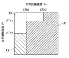
図6は、出力形式の判定基準を説明するための図である。
【0073】
まず、文字認識確度Cn の閾値として、例えば小さい方の閾値CTh1と大きい方の閾値CTh2とが設定され、文字連続性度Pn の閾値として、例えば小さい方の閾値PTh1と大きい方の閾値PTh2とが設定される。
【0074】
出力形式判定部33は、まず、文字認識確度Cn が大きい方の閾値CTh2より大きい文字画像を、文字コードデータに変換する旨の判定を行う(S28でYES、S33)。出力形式判定部33は、また、文字認識確度Cn が小さい方の閾値CTh1より大きく、且つ文字連続性度Pn が小さい方の閾値PTh1より大きい文字画像も、文字コードを正しく認識していると判断して、文字コードデータに変換する旨の判定を行う(S29でYES、S33)。すなわち、文字認識確度Cn が非常に大きい文字画像(Cn >CTh2)は、文字コードデータに変換すると判定され、文字認識確度Cn が中ぐらいの文字画像(CTh1<Cn <CTh2)は、文字連続性度Pn が閾値PTh1より大きい場合に限って文字コードデータに変換すると判定される。
【0075】
上記の2つのステップS28およびS29で文字コードデータに変換しないと判定された文字画像は、文字連続性度Pn により、さらに2つの出力形式に分類されて判定される。すなわち、文字コードデータに変換しないと判定された文字画像のうち、文字連続性度Pn が閾値PTh2より大きい文字画像は、入力された画像データ中の文字画像を切り出して文字画像データを作成すると判定される。
一方、文字コードデータに変換しないと判定された文字画像のうち、文字連続性度Pn が閾値PTh2以下の文字画像は、入力された画像データのまま元の位置に残すと判定される。
【0076】
このように、文字認識部31により文字コードが認識された文字画像は、出力形式判定部33により、最終的に3つに分類される。すなわち、個々の文字画像は、確実に文字コードが認識されたと判断されて、文字コードデータで出力する旨の判定が行われたもの(図6中のA1 で示す領域)と、文字画像には違いないが正しい文字コードが認識できたか否かが疑わしい文字画像と判断されて、隣接する文字コードデータに重なることなく連続して配置される文字画像データで出力する旨の判定が行われたもの(図6中のA2 で示す領域)と、近隣文字画像との連続性が少なく、非文字画像である図形画像であるにもかかわらず誤って文字コードが認識された文字画像であると判断されて、入力された画像データのまま元の位置に残す旨の判定が行われたもの(図6中のA3 で示す領域)と、に分類される。
【0077】
そして、注目する文字画像の順番を示す変数nを繰り上げ(S34)、画像データ内の全文字画像について、上記の処理を繰り返し行う(S35)。
【0078】
このようにして、画像データ中の個々の文字画像について出力形式の判定処理が終了すると、図4に示すメインフローチャートに戻り、文字画像データの作成が行われる(S16)。すなわち、文字画像データ作成部34は、文字認識部31から出力される文字画像の位置情報にしたがって、画像データ中の文字画像を切り出して文字画像データを作成する。このとき、個々の文字画像ごとに外接矩形領域の画像データが切り出される。
【0079】
ここで、文字画像データとして出力する文字画像を、原稿を読み取って得られた画像データとして元の位置に残さず、個々の文字画像単位で切り出すのは、文字コードデータと文字画像データとが重ならないようにするためである。つまり、一般に、入力フォントと出力フォントとが全く同じである場合は少ないので、例えば文字画像から変換された文字コードデータが配置される位置と、入力時の画像データ中の文字画像の位置とは、多少ずれてしまう。したがって、文字画像を一文字画像ずつ切り出さずに元の画像データとして残した場合、そのままで文字コードデータを配置すると、文字コードデータと原稿を読み取って得られた元の画像データ中の文字画像とが重なるといった問題が生じ得る。そこで、本実施形態では、一文字画像ずつ切り出しておいて、文字画像データを作成し、例えば文字コードデータを出力フォントで配置した位置に続けて、切り出しておいた文字画像データを配置する。
【0080】
また、文字画像データ作成部34は、文字画像データを作成する際に、文字画像の外接矩形内に対して、エッジ強調、または当該文字画像に適したγ変換を行う。これにより、例えばビットマップで表された文字画像データでも、用紙に印刷して鮮明な文字を再現することができる。
【0081】
次に、文字消去処理が行われる(S17)。すなわち、文字画像から文字コードデータまたは文字画像データを得た後、文字消去部35により、原稿を読み取ることによって入力されたカラーの画像データから、文字コードデータまたは文字画像データとされた後の元の文字画像が消去される。
【0082】
図7は、文字消去処理を説明するための図である。図7に示すように、個々の文字画像の外接矩形内における画像データ(図7(A))から、文字画像に当たる部分を一旦消去し(図7(B))、周囲の画像データで補完する(図7(C))。消去する部分は、当該文字画像の外接矩形内におけるモノクロ2値画像データから黒を2〜3画素膨張させる処理を行うことによって求める。なお、原稿を読み取ることによって入力された元の画像データから文字画像に当たる部分を除去した後の画像データには、図7(B)に示すように、文字画像以外の画像データ、すなわち、写真や線画に対応する画像、背景画像などが残っている。
【0083】
以上の処理を実施することにより、例えば図8に示すように、画像データ中の文字画像から、文字コードデータD1 と文字画像データD2 とが、また、非文字画像である図形画像をそのまま残した画像データD3 が得られる。なお、図9は、文字コードデータ、文字画像データ、および画像データの内容を別々に示す図である。図8および図9に示されるように、非文字画像である図形画像であるにもかかわらず誤って文字コードが認識された孤立して存在している文字画像は、文字コードデータに変換されないので、図12のように図形画像の部分に誤認識の文字コードデータが出力されることはない。
【0084】
そして、これらの文字コードデータ、文字画像データ、および画像データは、所定のファイル形式でページ内に配置されて保存される(S18)。なお、スキャン&プリントボタンが選択されている場合は、所定のデータがプリンタ60に送信されて用紙に印刷される。
【0085】
このように、本実施形態によれば、文字画像から文字コードを認識した後に、当該文字画像を文字コードデータに変換するか否かの判定を、文字連続性度を用いて行うようにしたので、非文字画像である図形画像であるにもかかわらず誤って文字コードが認識されて、文字コードデータとして出力される事態を有効に防止することができる。
【0086】
しかも、文字連続性度を用いることにより、文字コードを認識する確からしさに高目の厳しい閾値を設けなくても誤認識の文字コードデータを除去することが可能となるため、入力された画像データ中の文字画像が文字コードデータに変換される割合を高く維持することができる。
【0087】
本発明は、上記した実施形態のみに限定されるものではなく、特許請求の範囲内において、種々改変することができる。
【0088】
例えば、上記実施形態では、入力された画像データの色空間を、RGB表色系からLab表色系に変換して画像処理するようにしたが、スキャナ50で読み取って得られた画像データのRGB表色系等、他の色空間を使用して画像処理を行うことも可能である。
【0089】
また、上述した文字画像の連続性に着目した第1〜第5の評価ポイントを算出する方法は、上記実施形態で示した式等に限定されるものではない。例えば、次式により第2の評価ポイントP2nを計算することも可能である。
【0090】
【数4】
また、上記実施形態では、文字連続性度Pn は、第1〜5の評価ポイントに基づいて総合的に求められるが、これに限定されるものではない。文字連続性度Pn は、例えば、第1〜5の評価ポイントのうちの一つ、あるいは二つ以上を任意に組み合わせたものに基づいて求められるようにすることも可能である。
【0092】
また、上記実施形態では、出力形式判定部33は、文字認識確度Cn と文字連続性度Pn とに基づいて、図6に示す方法で、各文字画像についての出力形式の判定を行っているが、これに限定されるものではない。出力形式判定部33は、例えば、文字認識確度Cn の閾値CTh を文字連続性度Pn に応じて連続的に変化させる図10に示す方法で、各文字画像についての出力形式の判定を行うことも可能である。
【0093】
また、簡易な出力形式の判定処理を行う場合には、文字画像から文字コードを認識する確からしさの度合いを定量的に(例えば10段階で)検出することなく、文字画像から文字コードを認識できたか否かのみを検出し、出力形式判定部33が、文字コードが認識された文字画像を文字コードデータに変換するか否かを、文字連続性度を用いて判定するようにしてもよい。
【0094】
さらに、上記実施形態では、画像認識装置としてコンピュータを例に挙げて説明したが、本発明の画像認識装置はこれに限定されるものではなく、例えば同様の処理をスキャナで行ってコンピュータやプリンタ等に送信するシステム、スキャナから直接画像データを受信してプリンタで同様の処理を行うシステム、原稿の読み取りから用紙への印刷までの処理をカラーのデジタルコピー機ですべて行うシステム、等にも適用することが可能である。
【0095】
なお、上記した実施形態において、画像認識の制御は、上記した処理手順(図4、図5参照)を記述した所定のプログラムを主制御部11が実行することによって行われるものであり、この所定のプログラムは、コンピュータ読取可能な記録媒体(例えば、フロッピーディスクやCD−ROM等)によって提供されることもできる。また、この所定のプログラムは、上記各処理を実行するアプリケーションソフトウェアとして提供されてもよいし、コンピュータ、デジタルコピー機、スキャナ、プリンタ等の各情報機器や管理サーバの一機能として各情報機器や管理サーバのソフトウェアに組み込んでもよい。
【0096】
【発明の効果】
以上説明したように、本発明によれば、文字画像から文字コードを認識した後に、当該文字画像を文字コードデータに変換するか否かの判定を、文字連続性度を用いて行うようにしたので、非文字画像である図形画像であるにもかかわらず誤って文字コードが認識されて、文字コードデータとして出力される事態を有効に防止することができる。
【0097】
しかも、文字連続性度を用いることにより、文字コードを認識する確からしさに高目の厳しい閾値を設けなくても誤認識の文字コードデータを除去することが可能となるため、入力された画像データ中の文字画像が文字コードデータに変換される割合を高く維持することができる。
【0098】
また、文字コードデータに変換しないと判定された文字画像のうち文字連続性度が所定値以上の文字画像を切り出して文字画像データを作成し、隣接する文字コードデータに重なることなく連続して配置するようにしたので、文字コードデータと文字画像データとを重なることなく出力することが可能となる。
【図面の簡単な説明】
【図1】 本発明の実施形態に係る画像認識装置を含む情報機器システムの構成を示す図である。
【図2】 図1に示されるコンピュータの概略構成を示すブロック図である。
【図3】 各文字画像の位置情報を説明するための図である。
【図4】 画像認識処理を示すフローチャートである。
【図5】 図4に示される出力形式判定処理を示すサブルーチンのフローチャートである。
【図6】 出力形式の判定基準を説明するための図である。
【図7】 文字消去処理を説明するための図である。
【図8】 文字コードデータ、文字画像データ、および非文字画像である図形画像をそのまま残した画像データをあわせて配置した一例を示す図である。
【図9】 文字コードデータ、文字画像データ、および画像データの内容を別々に示す図である。
【図10】 出力形式の他の判定基準を説明するための図である。
【図11】 非文字である図形が文字部の中に埋め込まれた原稿の一例を示す図である。
【図12】 従来の画像認識装置により、図11の原稿を読み取って得られた画像データを画像処理して出力した一例を示す図である。
【符号の説明】
10…コンピュータ(画像認識装置)、
31…文字認識部、
33…出力形式判定部、
34…文字画像データ作成部、
36…ファイル作成部。[0001]
BACKGROUND OF THE INVENTION
The present invention relates to an image recognition technique, and more particularly to an image recognition technique for processing for determining whether or not to convert a character image in input image data into character code data.
[0002]
[Prior art]
A recent image recognition apparatus can recognize a character image as a character code with extremely high accuracy if it is a document with good scanning conditions (for example, a document composed of only characters of the same font). However, if the quality of the characters on the document is poor or the layout of the characters on the document is complicated, the recognition accuracy for recognizing the character image as a character code is greatly reduced, and the number of character images that are erroneously recognized increases. End up.
[0003]
In order to solve such a problem, a system that stores all image data obtained by reading a document for backup is known. However, as a matter of course, the capacity of the file stored including the backup image data is significantly larger than the input image data.
[0004]
Therefore, an image recognition apparatus has been proposed that outputs only character images that are highly likely to be erroneously recognized as character image data (for example, bitmap format image data) without converting them into character code data. Here, for determining the possibility of erroneous recognition, for example, information on the probability of recognizing a character code detected from a result such as a similarity to a standard pattern stored in advance is used.
[0005]
[Problems to be solved by the invention]
However, with only the probability information for recognizing the character code, it is possible to determine which character image in the image data is correctly recognized as the character code and which character image is erroneously recognized. Is not so high, and it is difficult to sufficiently remove character images that are erroneously recognized as a result.
[0006]
In particular, recently, originals to be read are diversified, and color originals and originals with complicated layouts are increasing. Along with this, it has become difficult to extract a character region where a character image exists from image data. Therefore, for example, when reading a document in which a non-character graphic as shown in FIG. 11 is embedded in the character portion, as shown in FIG. 12, the graphic is a non-character image in the obtained image data. A situation may occur in which a character code is erroneously recognized from an image and output as character code data. In the figure, symbol E1 represents character code data obtained by erroneously recognizing a character code from a graphic image, and symbol E2 represents character code data obtained by erroneously recognizing a character code from a character image. In addition, the probability of recognizing the character code when the graphic image is converted to the character code data E1 may not be much different from the original character image. For this reason, if it is determined whether or not conversion into character code data is performed only with information on the probability of recognizing the character code, the character code data obtained by erroneous recognition from the graphic image cannot be removed.
[0007]
On the other hand, Japanese Patent Laid-Open No. 8-55185 proposes a technique of extracting a character area while examining a positional relationship with a neighboring character image at the stage of extracting a character area in which character images are present in image data. ing. In Japanese Patent Laid-Open No. 8-161421, in the stage of extracting a character area, a character candidate area that is a candidate for a character area is first extracted by examining the positional relationship with neighboring character images. A technique has been proposed in which a character area is reconstructed with a character image that can recognize a character code in the image data. However, any technique disclosed in the above publication is merely a technique for extracting a character region from image data.
[0008]
The present invention has been made in view of the above-described problems of the prior art, and an object of the present invention is to perform erroneous recognition while increasing the rate at which a character image in input image data is converted into character code data. This is to effectively prevent the output of the character code data.
[0009]
[Means for Solving the Problems]
The object of the present invention is achieved by the following means.
[0010]
(1) In the image recognition device, the degree of continuity between a character recognition unit that recognizes a character code from a character image in input image data and a neighboring character image of the character image in which the character code is recognized A character continuity detection unit that detects a certain character continuity level and a character image in which the character code is recognized The magnitude relationship of the degree of character continuity with respect to the first threshold value and the smaller second threshold value An output format determination unit for determining Then, the character image whose character continuity is determined to be larger than the first threshold is converted into character code data, and it is determined that the character continuity is larger than the second threshold and smaller than the first threshold. Cut out character images and create character image data that is arranged consecutively without overlapping adjacent character code data An image recognition apparatus.
[0011]
(2) The character continuity detector detects a distance between a character image in which a character code is recognized and a character image in the vicinity of the character image, a character image in which the character code is recognized, and a character image in the vicinity of the character image. Difference in font size between the character image in which the character code is recognized and the character type difference between the character image and the character image in the vicinity of the character image, and the sequence of consecutive character images including the character image in which the character code is recognized. At least one or more of color differences between a character image whose length and character code are recognized and a character image adjacent to the character image is detected. Image recognition device.
[0014]
( 3 The above (1), further comprising a file creation unit for creating an electronic file Or (2) The image recognition apparatus described in 1.
[0015]
( 4 (1) to (1), further comprising a scanner unit for obtaining image data by reading a document. 3 The image recognition device according to any one of the above.
[0016]
( 5 (1) to (1), further comprising: an image data receiving unit for receiving image data; and a printing unit for printing the data on paper. 4 The image recognition device according to any one of the above.
[0017]
( 6 ) In the image recognition method, the character continuity, which is the degree of continuity between the process of recognizing the character code from the character image in the input image data and the character image for which the character code is recognized, with the adjacent character image Process of detecting degree and character image with recognized character code The magnitude relationship of the degree of character continuity with respect to the first threshold value and the second threshold value smaller than the first threshold value The process of judging, A character image whose character continuity is determined to be larger than the first threshold is converted into character code data, and a character image whose character continuity is determined to be larger than the second threshold and smaller than the first threshold. A process of creating character image data that is continuously arranged without overlapping adjacent character code data; An image recognition method comprising:
[0018]
( 7 ) A computer-readable recording medium having an image recognition program recorded therein, a process of recognizing a character code from a character image in input image data, and neighboring character images of the character image in which the character code is recognized The process of detecting the character continuity, which is the degree of continuity between and the character image with the character code recognized The magnitude relationship of the degree of character continuity with respect to the first threshold value and the second threshold value smaller than the first threshold value The process of judging, A character image whose character continuity is determined to be larger than the first threshold is converted into character code data, and a character image whose character continuity is determined to be larger than the second threshold and smaller than the first threshold. A process of creating character image data that is continuously arranged without overlapping adjacent character code data; A computer-readable recording medium on which an image recognition program for causing a computer to execute is recorded.
[0019]
DETAILED DESCRIPTION OF THE INVENTION
Hereinafter, embodiments of the present invention will be described with reference to the accompanying drawings.
[0020]
FIG. 1 is a configuration diagram of an information equipment system including an image recognition apparatus according to the first embodiment of the present invention.
[0021]
The
[0022]
The
[0023]
FIG. 2 is a block diagram illustrating a schematic configuration of the
[0024]
The
[0025]
An operation instruction of the information equipment system shown in FIG. 1 can be issued from the
[0026]
For example, a scan & file button and a scan & print button are displayed on the
[0027]
When an operation instruction is issued using the scan & print button, the image data obtained by reading the
[0028]
Next, the
[0029]
The
[0030]
The
Furthermore, the
[0031]
For example, the font type is classified and classified into a serif system and a sans serif system. The font size is obtained by comparing the size of the circumscribed rectangle of each character image with the size of the character code data obtained by recognizing the character code in a general font. Information such as the character height and character width of a predetermined representative font, that is, font metric data is stored in advance as data.
[0032]
The character
[0033]
The output
[0034]
The
[0035]
The
[0036]
Next, the operation of the
[0037]
First, the color space is converted from the RGB color system to the Lab color system for the image data obtained by reading the original with the scanner 50 (S11). Since the Lab color system does not depend on individual information devices such as a scanner or a printer, it can be handled as common color information on the network N.
[0038]
Next, OCR preprocessing is performed to create image data to be input to the character recognition unit 31 (S12). Since the
[0039]
The monochrome binary image data obtained by the OCR preprocessing is input to the
[0040]
Next, a character color detection process is performed (S14). That is, the color of each character image whose character code has been recognized is detected by the character
[0041]
When a character image is converted into character code data and output, the character code data is output by specifying a color based on the color information of each character image detected by the character
[0042]
Then, an output format determination process is performed for each character image in the character region (S15). That is, the output
[0043]
The output
[0044]
Then, the output
[0045]
Next, an output format determination process for a character image whose character code has been recognized will be described in more detail.
[0046]
From the
[0047]
The degree of character continuity, that is, the evaluation value of character character, is the distance between a character image in which the character code is recognized and the character image in the vicinity of the character image, the character image in which the character code is recognized and the character in the vicinity of the character image A difference in font size from the image, a difference in font type between a character image whose character code is recognized and a character image in the vicinity of the character image, and a sequence of consecutive character images including character images whose character code is recognized 5 items, the color difference between the character image for which the character code is recognized and the character image adjacent to the character image, and the character image adjacent to the character image are examined in order, and an evaluation point focusing on the continuity of the character image is calculated for each item Is detected.
[0048]
Specifically, as shown in FIG. 5, first, a variable n indicating the order of individual character images of interest is initialized (S21).
[0049]
Then, a first evaluation point is calculated based on the distance between the character image whose character code is recognized and the character image adjacent to the character image (S22). Here, the positional information (see FIG. 3) of ± k character images before and after the character image of interest is examined, and the first evaluation point P1n is calculated by the following equation. The subscripts in the formula indicate the order of individual character images (the same applies to the following formulas).
[0050]
[Expression 1]
However, when P1n <0, P1n = 0
M1: Maximum value of the first evaluation point
X1: left X coordinate of the circumscribed rectangle of the character image whose character code is recognized
X2: Right X coordinate of the circumscribed rectangle of the character image whose character code is recognized
Y1: Upper Y coordinate of the circumscribed rectangle of the character image whose character code is recognized
Y2: Lower Y coordinate of the circumscribed rectangle of the character image whose character code is recognized
It is.
[0052]
As shown in the above formula, the first evaluation point becomes smaller as the distance from the neighboring character image becomes larger. That is, as the character image of interest is further away from the neighboring character image, the continuity is smaller and the possibility of being a character image is lower.
[0053]
As can be seen from the above formula, for example, the character image at the right end or the left end of the line in which a plurality of character images are formed side by side is considered, so that the distance from the neighboring character image on the right side of the character image of interest and the left side The distance from the neighboring character image is checked, and the smaller one of the two is used for the evaluation point calculation.
[0054]
Next, a second evaluation point is calculated based on the difference in font size between the character image whose character code is recognized and the character image adjacent to the character image (S23). Here, the font size of ± k character images before and after the character image of interest is checked, and the second evaluation point P2n is calculated by the following equation.
[0055]
[Expression 2]
However, when P2n <0, P2n = 0
M1: Maximum value of the second evaluation point
S: Font size
It is.
[0057]
The denominator of the above formula represents the average font size of neighboring character images. As shown in the above equation, the greater the difference in font size from the neighboring character image, the smaller the continuity and the smaller the second evaluation point.
[0058]
Next, a third evaluation point is calculated based on the difference in font type between the character image whose character code is recognized and the character image adjacent to the character image (S24).
Here, the font type of ± k character images before and after the target character image is checked, and the number of character images whose font types are different from the target character image is Nf. P3n is calculated.
[0059]
P3n = M3-Nf
However, when P3n <0, P3n = 0
M3: Maximum value of the third evaluation point
It is.
[0060]
As shown in the above equation, the greater the difference in font type from the neighboring character image, the smaller the continuity and the third evaluation point.
[0061]
Next, a fourth evaluation point is calculated based on the length of the sequence of consecutive character images including the character image whose character code is recognized (S25). Here, the circumscribed rectangle intervals of the individual character images are sequentially examined before and after the character image of interest, and if the interval is equal to or greater than the predetermined threshold TH, it is determined that the character image string is separated. Note that the threshold value TH is preferably changed depending on, for example, the average size of neighboring character images. Then, with the target character image as the nth character image, one character image string includes the i1st character image present on the left side of the target character image to the i2th character image present on the right side of the target character image. If it is determined that there is, the fourth evaluation point P4n is calculated by the following equation.
[0062]
P4n = i2 -
However, when P4n> M4, P4n = M4
M4: Maximum value of the fourth evaluation point
It is.
[0063]
As shown in the above formula, the longer the character image string, the greater the continuity, and the fourth evaluation point becomes larger.
[0064]
Finally, a fifth evaluation point is calculated based on the color difference between the character image whose character code is recognized and the character image adjacent to the character image (S26). Here, the colors of ± k character images before and after the character image of interest are examined, and a fifth evaluation point P5n is calculated by the following equation.
[0065]
[Equation 3]
However, when P5n <0, P5n = 0
M5: Maximum value of the fifth evaluation point
L, a, b: values representing the color of the character image in the Lab color system
It is.
[0067]
As shown in the above equation, the greater the color difference from the neighboring character image, the smaller the continuity and the smaller the fifth evaluation point.
[0068]
From the first to fifth evaluation points obtained as described above, the character continuity degree Pn as a comprehensive evaluation point is calculated by the following equation (S27).
[0069]
Pn = W1 * P1n + W2 * P2n + W3 * P3n + W4 * P4n + W5 * P5n
However, W1 to W5 are weights for the respective evaluation points, and can be set as appropriate.
[0070]
On the other hand, apart from the character continuity Pn, a character recognition accuracy Cn, which is a degree of probability of recognizing the character code, is obtained for each character image.
[0071]
Then, the output
[0072]
FIG. 6 is a diagram for explaining an output format determination criterion.
[0073]
First, for example, a smaller threshold value CTh1 and a larger threshold value CTh2 are set as threshold values for the character recognition accuracy Cn. For example, a smaller threshold value PTh1 and a larger threshold value PTh2 are set as threshold values for the character continuity Pn. Is set.
[0074]
First, the output
[0075]
The character image determined not to be converted into the character code data in the above two steps S28 and S29 is further classified into two output formats and determined by the character continuity degree Pn. That is, among character images determined not to be converted into character code data, character images having a character continuity Pn greater than the threshold value PTh2 are determined to generate character image data by cutting out the character image in the input image data. Is done.
On the other hand, among character images determined not to be converted into character code data, character images having a character continuity Pn of a threshold value PTh2 or less are determined to remain in the original position as input image data.
[0076]
In this way, the character images whose character codes have been recognized by the
[0077]
Then, the variable n indicating the order of the character image of interest is incremented (S34), and the above processing is repeated for all character images in the image data (S35).
[0078]
In this way, when the output format determination process is completed for each character image in the image data, the process returns to the main flowchart shown in FIG. 4 to create the character image data (S16). That is, the character image
[0079]
Here, the character code data and the character image data are cut out in units of individual character images without leaving the character image output as the character image data in the original position as the image data obtained by reading the document. This is in order not to become. In other words, in general, there are few cases where the input font and the output font are exactly the same. For example, the position where the character code data converted from the character image is arranged and the position of the character image in the image data at the time of input are , It will shift slightly. Therefore, if the character image is left as original image data without being cut out one character image at a time, if the character code data is arranged as it is, the character code data and the character image in the original image data obtained by reading the original are obtained. Problems such as overlapping may occur. Therefore, in this embodiment, character image data is created by cutting out character images one by one, and the cut out character image data is placed, for example, following the position where the character code data is placed in the output font.
[0080]
Further, when creating the character image data, the character image
[0081]
Next, a character erasing process is performed (S17). That is, after obtaining character code data or character image data from a character image, the
[0082]
FIG. 7 is a diagram for explaining the character erasing process. As shown in FIG. 7, the portion corresponding to the character image is once deleted from the image data (FIG. 7A) in the circumscribed rectangle of each character image (FIG. 7B), and complemented with surrounding image data. (FIG. 7C). The portion to be erased is obtained by performing a process of expanding black by 2 to 3 pixels from monochrome binary image data in the circumscribed rectangle of the character image. As shown in FIG. 7B, the image data after removing the portion corresponding to the character image from the original image data input by reading the document includes image data other than the character image, that is, a photograph or The image corresponding to the line drawing, the background image, etc. remain.
[0083]
By performing the above processing, for example, as shown in FIG. 8, the character code data D1 and the character image data D2 and the graphic image which is a non-character image are left as they are from the character image in the image data. Image data D3 is obtained. FIG. 9 is a diagram separately showing the contents of the character code data, the character image data, and the image data. As shown in FIGS. 8 and 9, an isolated character image in which a character code is erroneously recognized despite being a graphic image that is a non-character image is not converted into character code data. As shown in FIG. 12, erroneously recognized character code data is not output to the graphic image portion.
[0084]
These character code data, character image data, and image data are arranged and stored in a page in a predetermined file format (S18). If the scan & print button is selected, predetermined data is transmitted to the
[0085]
As described above, according to the present embodiment, after the character code is recognized from the character image, the determination as to whether or not to convert the character image into character code data is performed using the character continuity degree. Therefore, it is possible to effectively prevent a situation in which a character code is erroneously recognized and output as character code data despite being a non-character image.
[0086]
In addition, by using the character continuity level, it is possible to remove erroneously recognized character code data without setting a strict threshold for the probability of recognizing the character code. It is possible to maintain a high rate of conversion of character images in the character code data.
[0087]
The present invention is not limited to the above-described embodiments, and various modifications can be made within the scope of the claims.
[0088]
For example, in the above embodiment, the color space of the input image data is converted from the RGB color system to the Lab color system and image processing is performed. However, the RGB of the image data obtained by reading with the
[0089]
In addition, the method for calculating the first to fifth evaluation points focusing on the continuity of the character image described above is not limited to the equations shown in the above embodiment. For example, the second evaluation point P2n can be calculated by the following equation.
[0090]
[Expression 4]
Moreover, in the said embodiment, although the character continuity degree Pn is calculated | required comprehensively based on the 1st-5th evaluation point, it is not limited to this. The character continuity degree Pn can be obtained based on, for example, one of the first to fifth evaluation points or an arbitrary combination of two or more.
[0092]
In the above embodiment, the output
[0093]
In addition, when performing a simple output format determination process, it is possible to recognize a character code from a character image without quantitatively detecting the probability of recognizing the character code from the character image (for example, in 10 steps). The output
[0094]
Furthermore, in the above-described embodiment, the computer has been described as an example of the image recognition device. However, the image recognition device of the present invention is not limited to this, and for example, a computer, a printer, or the like by performing the same processing with a scanner. This is also applicable to systems that send image data directly from scanners, systems that receive image data directly from a scanner and perform similar processing with a printer, systems that perform all processes from reading a document to printing on paper with a color digital copier, etc. It is possible.
[0095]
In the above-described embodiment, the image recognition control is performed by the
[0096]
【The invention's effect】
As described above, according to the present invention, after the character code is recognized from the character image, it is determined whether to convert the character image into character code data using the character continuity level. Therefore, it is possible to effectively prevent a situation in which a character code is erroneously recognized and output as character code data even though it is a non-character image.
[0097]
In addition, by using the character continuity level, it is possible to remove erroneously recognized character code data without setting a strict threshold for the probability of recognizing the character code. It is possible to maintain a high rate of conversion of character images in the character code data.
[0098]
In addition, character image data whose character continuity is determined not to be converted into character code data is cut out to create character image data, and arranged continuously without overlapping adjacent character code data. Thus, the character code data and the character image data can be output without overlapping.
[Brief description of the drawings]
FIG. 1 is a diagram showing a configuration of an information equipment system including an image recognition apparatus according to an embodiment of the present invention.
FIG. 2 is a block diagram showing a schematic configuration of a computer shown in FIG.
FIG. 3 is a diagram for explaining position information of each character image.
FIG. 4 is a flowchart showing image recognition processing.
FIG. 5 is a subroutine flowchart showing an output format determination process shown in FIG. 4;
FIG. 6 is a diagram for explaining an output format determination criterion;
FIG. 7 is a diagram for explaining character erasing processing;
FIG. 8 is a diagram showing an example in which character code data, character image data, and image data in which a graphic image that is a non-character image is left as they are arranged.
FIG. 9 is a diagram separately showing the contents of character code data, character image data, and image data.
FIG. 10 is a diagram for explaining another determination criterion for an output format;
FIG. 11 is a diagram illustrating an example of a document in which a non-character graphic is embedded in a character part.
12 is a diagram illustrating an example in which image data obtained by reading the document in FIG. 11 is subjected to image processing and output by a conventional image recognition apparatus.
[Explanation of symbols]
10: Computer (image recognition device),
31 ... Character recognition unit,
33 ... Output format determination unit,
34 ... character image data creation unit,
36: File creation unit.
Claims (7)
入力された画像データ中の文字画像から文字コードを認識する文字認識部と、
文字コードが認識された文字画像についての、近隣の文字画像との連続性の度合いである文字連続性度を検出する文字連続性度検出部と、
文字コードが認識された文字画像についての文字連続性度の、第1の閾値及びそれよりも小さい第2の閾値との大小関係を判定する出力形式判定部と、
を有し、
文字連続性度が第1の閾値よりも大きいと判定された文字画像を文字コードデータに変換し、文字連続性が第2の閾値よりも大きく第1の閾値よりも小さいと判定された文字画像を切り出して、隣接する文字コードデータに重なることなく連続して配置される文字画像データを作成することを特徴とする画像認識装置。In an image recognition device,
A character recognition unit that recognizes a character code from a character image in input image data;
A character continuity detecting unit that detects a character continuity that is a degree of continuity with a neighboring character image for a character image in which a character code is recognized;
An output format determination unit that determines the magnitude relationship between the first threshold and the second threshold smaller than the first threshold of the character continuity of the character image for which the character code is recognized;
I have a,
A character image whose character continuity is determined to be larger than the first threshold is converted into character code data, and a character image whose character continuity is determined to be larger than the second threshold and smaller than the first threshold. An image recognition apparatus characterized by creating character image data that is continuously arranged without overlapping adjacent character code data .
入力された画像データ中の文字画像から文字コードを認識する過程と、
文字コードが認識された文字画像についての、近隣の文字画像との連続性の度合いである文字連続性度を検出する過程と、
文字コードが認識された文字画像についての文字連続性度の、第1の閾値及びそれよりも小さい第2の閾値との大小関係を判定する過程と、
文字連続性度が第1の閾値よりも大きいと判定された文字画像を文字コードデータに変換し、文字連続性が第2の閾値よりも大きく第1の閾値よりも小さいと判定された文字画像を切り出して、隣接する文字コードデータに重なることなく連続して配置される文字画像データを作成する過程と、
を有することを特徴とする画像認識方法。In the image recognition method,
The process of recognizing the character code from the character image in the input image data,
A process of detecting a character continuity level, which is a degree of continuity with a neighboring character image, for a character image whose character code is recognized;
Determining a magnitude relationship between a first threshold value and a second threshold value smaller than the first threshold value of the character continuity of the character image in which the character code is recognized;
A character image whose character continuity is determined to be larger than the first threshold is converted into character code data, and a character image whose character continuity is determined to be larger than the second threshold and smaller than the first threshold. A process of creating character image data that is continuously arranged without overlapping adjacent character code data;
An image recognition method comprising:
入力された画像データ中の文字画像から文字コードを認識する過程と、
文字コードが認識された文字画像についての、近隣の文字画像との連続性の度合いである文字連続性度を検出する過程と、
文字コードが認識された文字画像についての文字連続性度の、第1の閾値及びそれよりも小さい第2の閾値との大小関係を判定する過程と、
文字連続性度が第1の閾値よりも大きいと判定された文字画像を文字コードデータに変換し、文字連続性が第2の閾値よりも大きく第1の閾値よりも小さいと判定された文字画像を切り出して、隣接する文字コードデータに重なることなく連続して配置される文字画像データを作成する過程と、
をコンピュータに実行させるための画像認識プログラムを記録したコンピュータ読取可能な記録媒体。A computer-readable recording medium recording an image recognition program,
The process of recognizing the character code from the character image in the input image data,
A process of detecting a character continuity level, which is a degree of continuity with a neighboring character image, for a character image whose character code is recognized;
Determining a magnitude relationship between a first threshold value and a second threshold value smaller than the first threshold value of the character continuity of the character image in which the character code is recognized;
A character image whose character continuity is determined to be larger than the first threshold is converted into character code data, and a character image whose character continuity is determined to be larger than the second threshold and smaller than the first threshold. A process of creating character image data that is continuously arranged without overlapping adjacent character code data;
A computer-readable recording medium on which an image recognition program for causing a computer to execute is recorded.
Priority Applications (2)
| Application Number | Priority Date | Filing Date | Title |
|---|---|---|---|
| JP2000195146A JP4613397B2 (en) | 2000-06-28 | 2000-06-28 | Image recognition apparatus, image recognition method, and computer-readable recording medium on which image recognition program is recorded |
| US09/892,617 US7149352B2 (en) | 2000-06-28 | 2001-06-28 | Image processing device, program product and system |
Applications Claiming Priority (1)
| Application Number | Priority Date | Filing Date | Title |
|---|---|---|---|
| JP2000195146A JP4613397B2 (en) | 2000-06-28 | 2000-06-28 | Image recognition apparatus, image recognition method, and computer-readable recording medium on which image recognition program is recorded |
Publications (2)
| Publication Number | Publication Date |
|---|---|
| JP2002015280A JP2002015280A (en) | 2002-01-18 |
| JP4613397B2 true JP4613397B2 (en) | 2011-01-19 |
Family
ID=18693855
Family Applications (1)
| Application Number | Title | Priority Date | Filing Date |
|---|---|---|---|
| JP2000195146A Expired - Fee Related JP4613397B2 (en) | 2000-06-28 | 2000-06-28 | Image recognition apparatus, image recognition method, and computer-readable recording medium on which image recognition program is recorded |
Country Status (2)
| Country | Link |
|---|---|
| US (1) | US7149352B2 (en) |
| JP (1) | JP4613397B2 (en) |
Families Citing this family (13)
| Publication number | Priority date | Publication date | Assignee | Title |
|---|---|---|---|---|
| JP4189506B2 (en) * | 2000-06-09 | 2008-12-03 | コニカミノルタビジネステクノロジーズ株式会社 | Apparatus, method and recording medium for image processing |
| US20050216564A1 (en) * | 2004-03-11 | 2005-09-29 | Myers Gregory K | Method and apparatus for analysis of electronic communications containing imagery |
| JP2005301664A (en) * | 2004-04-12 | 2005-10-27 | Fuji Xerox Co Ltd | Image dictionary forming device, encoding device, data file, image dictionary forming method, and program thereof |
| US7734092B2 (en) * | 2006-03-07 | 2010-06-08 | Ancestry.Com Operations Inc. | Multiple image input for optical character recognition processing systems and methods |
| JP2007304864A (en) * | 2006-05-11 | 2007-11-22 | Fuji Xerox Co Ltd | Character recognition processing system and program |
| JP4600491B2 (en) * | 2008-02-26 | 2010-12-15 | 富士ゼロックス株式会社 | Image processing apparatus and image processing program |
| JP5322517B2 (en) | 2008-07-08 | 2013-10-23 | キヤノン株式会社 | Image processing apparatus and method |
| US8373724B2 (en) | 2009-01-28 | 2013-02-12 | Google Inc. | Selective display of OCR'ed text and corresponding images from publications on a client device |
| US9008425B2 (en) * | 2013-01-29 | 2015-04-14 | Xerox Corporation | Detection of numbered captions |
| JP2016015115A (en) * | 2014-06-09 | 2016-01-28 | 株式会社リコー | Information processing device, information processing method, and recording medium |
| CN110636181A (en) * | 2016-03-01 | 2019-12-31 | 京瓷办公信息系统株式会社 | Information processing apparatus |
| JP6530432B2 (en) * | 2017-02-03 | 2019-06-12 | 株式会社東芝 | Image processing apparatus, image processing method and program |
| JP2022072391A (en) * | 2020-10-29 | 2022-05-17 | 株式会社リコー | Image processing apparatus, image processing method, and program |
Citations (5)
| Publication number | Priority date | Publication date | Assignee | Title |
|---|---|---|---|---|
| JPH01191992A (en) * | 1988-01-28 | 1989-08-02 | Canon Inc | Character recognizing device |
| JPH0290384A (en) * | 1988-09-28 | 1990-03-29 | Ricoh Co Ltd | Post-processing system for character recognizing device |
| JPH04293185A (en) * | 1991-03-20 | 1992-10-16 | Ricoh Co Ltd | Filing device |
| JPH05108872A (en) * | 1991-10-18 | 1993-04-30 | Canon Inc | Method and device for character recognition |
| JPH1185899A (en) * | 1997-09-05 | 1999-03-30 | Tsubasa Syst Kk | Character reader, its method and record medium |
Family Cites Families (15)
| Publication number | Priority date | Publication date | Assignee | Title |
|---|---|---|---|---|
| JPS6274181A (en) * | 1985-09-27 | 1987-04-04 | Sony Corp | Character recognizing device |
| JPH0634256B2 (en) * | 1987-03-04 | 1994-05-02 | シャープ株式会社 | Contact character cutting method |
| JPH0537700A (en) | 1991-07-26 | 1993-02-12 | Ricoh Co Ltd | Facsimile equipment |
| EP0564201B1 (en) * | 1992-03-30 | 2000-05-24 | Canon Kabushiki Kaisha | Image processing apparatus and method |
| JPH0620089A (en) * | 1992-06-30 | 1994-01-28 | Canon Inc | Data input device and data processor |
| JPH0855185A (en) | 1994-08-15 | 1996-02-27 | Matsushita Electric Ind Co Ltd | Character recognition device |
| JP3400151B2 (en) | 1994-12-08 | 2003-04-28 | 株式会社東芝 | Character string region extraction apparatus and method |
| JP3602596B2 (en) * | 1995-02-22 | 2004-12-15 | 株式会社東芝 | Document filing apparatus and method |
| JP3345224B2 (en) * | 1995-03-06 | 2002-11-18 | 富士通株式会社 | Pattern extraction device, pattern re-recognition table creation device, and pattern recognition device |
| JPH0991371A (en) | 1995-09-21 | 1997-04-04 | Nippon Telegr & Teleph Corp <Ntt> | Character display device |
| JP3427692B2 (en) * | 1996-11-20 | 2003-07-22 | 松下電器産業株式会社 | Character recognition method and character recognition device |
| US6327387B1 (en) * | 1996-12-27 | 2001-12-04 | Fujitsu Limited | Apparatus and method for extracting management information from image |
| JPH10290349A (en) | 1997-04-14 | 1998-10-27 | Ricoh Co Ltd | Facsimile equipment |
| JPH10313372A (en) | 1997-05-13 | 1998-11-24 | Sanyo Electric Co Ltd | Data communication equipment |
| JP2000353215A (en) * | 1999-06-11 | 2000-12-19 | Nec Corp | Character recognition device and recording medium where character recognizing program is recorded |
-
2000
- 2000-06-28 JP JP2000195146A patent/JP4613397B2/en not_active Expired - Fee Related
-
2001
- 2001-06-28 US US09/892,617 patent/US7149352B2/en not_active Expired - Fee Related
Patent Citations (5)
| Publication number | Priority date | Publication date | Assignee | Title |
|---|---|---|---|---|
| JPH01191992A (en) * | 1988-01-28 | 1989-08-02 | Canon Inc | Character recognizing device |
| JPH0290384A (en) * | 1988-09-28 | 1990-03-29 | Ricoh Co Ltd | Post-processing system for character recognizing device |
| JPH04293185A (en) * | 1991-03-20 | 1992-10-16 | Ricoh Co Ltd | Filing device |
| JPH05108872A (en) * | 1991-10-18 | 1993-04-30 | Canon Inc | Method and device for character recognition |
| JPH1185899A (en) * | 1997-09-05 | 1999-03-30 | Tsubasa Syst Kk | Character reader, its method and record medium |
Also Published As
| Publication number | Publication date |
|---|---|
| JP2002015280A (en) | 2002-01-18 |
| US20020015524A1 (en) | 2002-02-07 |
| US7149352B2 (en) | 2006-12-12 |
Similar Documents
| Publication | Publication Date | Title |
|---|---|---|
| JP4631133B2 (en) | Apparatus, method and recording medium for character recognition processing | |
| US6865290B2 (en) | Method and apparatus for recognizing document image by use of color information | |
| US6574375B1 (en) | Method for detecting inverted text images on a digital scanning device | |
| JP4655335B2 (en) | Image recognition apparatus, image recognition method, and computer-readable recording medium on which image recognition program is recorded | |
| JP4065460B2 (en) | Image processing method and apparatus | |
| US8023147B2 (en) | Image processing method and image processing apparatus | |
| US8126270B2 (en) | Image processing apparatus and image processing method for performing region segmentation processing | |
| US7321688B2 (en) | Image processor for character recognition | |
| US7805022B2 (en) | Image processing apparatus, image processing method and computer program | |
| JP4613397B2 (en) | Image recognition apparatus, image recognition method, and computer-readable recording medium on which image recognition program is recorded | |
| US7796817B2 (en) | Character recognition method, character recognition device, and computer product | |
| EP1017011A2 (en) | Block selection of table features | |
| US11568623B2 (en) | Image processing apparatus, image processing method, and storage medium | |
| JP4077919B2 (en) | Image processing method and apparatus and storage medium therefor | |
| JP7433887B2 (en) | Devices, programs, and image processing methods for processing images | |
| US5467410A (en) | Identification of a blank page in an image processing system | |
| US6360006B1 (en) | Color block selection | |
| JP4232679B2 (en) | Image forming apparatus and program | |
| JP2010074342A (en) | Image processing apparatus, image forming apparatus, and program | |
| JP2021044803A (en) | Image processing device, image processing method, and program | |
| EP1296283A2 (en) | Half-tone dot elimination method and system thereof | |
| JP4710672B2 (en) | Character color discrimination device, character color discrimination method, and computer program | |
| JP2004080341A (en) | Image processor, image processing method, program, and recording medium | |
| JP3960756B2 (en) | Document image layout identification method and apparatus | |
| JP2021005315A (en) | Information processing device, program, and control method |
Legal Events
| Date | Code | Title | Description |
|---|---|---|---|
| A711 | Notification of change in applicant |
Free format text: JAPANESE INTERMEDIATE CODE: A712 Effective date: 20040423 |
|
| A621 | Written request for application examination |
Free format text: JAPANESE INTERMEDIATE CODE: A621 Effective date: 20070521 |
|
| RD03 | Notification of appointment of power of attorney |
Free format text: JAPANESE INTERMEDIATE CODE: A7423 Effective date: 20070601 |
|
| A977 | Report on retrieval |
Free format text: JAPANESE INTERMEDIATE CODE: A971007 Effective date: 20100402 |
|
| A131 | Notification of reasons for refusal |
Free format text: JAPANESE INTERMEDIATE CODE: A131 Effective date: 20100406 |
|
| A521 | Request for written amendment filed |
Free format text: JAPANESE INTERMEDIATE CODE: A523 Effective date: 20100603 |
|
| TRDD | Decision of grant or rejection written | ||
| A01 | Written decision to grant a patent or to grant a registration (utility model) |
Free format text: JAPANESE INTERMEDIATE CODE: A01 Effective date: 20100921 |
|
| A01 | Written decision to grant a patent or to grant a registration (utility model) |
Free format text: JAPANESE INTERMEDIATE CODE: A01 |
|
| A61 | First payment of annual fees (during grant procedure) |
Free format text: JAPANESE INTERMEDIATE CODE: A61 Effective date: 20101004 |
|
| R150 | Certificate of patent or registration of utility model |
Free format text: JAPANESE INTERMEDIATE CODE: R150 |
|
| FPAY | Renewal fee payment (event date is renewal date of database) |
Free format text: PAYMENT UNTIL: 20131029 Year of fee payment: 3 |
|
| S111 | Request for change of ownership or part of ownership |
Free format text: JAPANESE INTERMEDIATE CODE: R313111 |
|
| R350 | Written notification of registration of transfer |
Free format text: JAPANESE INTERMEDIATE CODE: R350 |
|
| LAPS | Cancellation because of no payment of annual fees |