JP4612829B2 - Image forming apparatus - Google Patents
Image forming apparatus Download PDFInfo
- Publication number
- JP4612829B2 JP4612829B2 JP2004323235A JP2004323235A JP4612829B2 JP 4612829 B2 JP4612829 B2 JP 4612829B2 JP 2004323235 A JP2004323235 A JP 2004323235A JP 2004323235 A JP2004323235 A JP 2004323235A JP 4612829 B2 JP4612829 B2 JP 4612829B2
- Authority
- JP
- Japan
- Prior art keywords
- sheet
- image forming
- forming apparatus
- detection unit
- processing apparatus
- Prior art date
- Legal status (The legal status is an assumption and is not a legal conclusion. Google has not performed a legal analysis and makes no representation as to the accuracy of the status listed.)
- Expired - Fee Related
Links
Images


Classifications
-
- G—PHYSICS
- G03—PHOTOGRAPHY; CINEMATOGRAPHY; ANALOGOUS TECHNIQUES USING WAVES OTHER THAN OPTICAL WAVES; ELECTROGRAPHY; HOLOGRAPHY
- G03G—ELECTROGRAPHY; ELECTROPHOTOGRAPHY; MAGNETOGRAPHY
- G03G15/00—Apparatus for electrographic processes using a charge pattern
- G03G15/65—Apparatus which relate to the handling of copy material
- G03G15/6552—Means for discharging uncollated sheet copy material, e.g. discharging rollers, exit trays
-
- B—PERFORMING OPERATIONS; TRANSPORTING
- B65—CONVEYING; PACKING; STORING; HANDLING THIN OR FILAMENTARY MATERIAL
- B65H—HANDLING THIN OR FILAMENTARY MATERIAL, e.g. SHEETS, WEBS, CABLES
- B65H31/00—Pile receivers
- B65H31/02—Pile receivers with stationary end support against which pile accumulates
-
- B—PERFORMING OPERATIONS; TRANSPORTING
- B65—CONVEYING; PACKING; STORING; HANDLING THIN OR FILAMENTARY MATERIAL
- B65H—HANDLING THIN OR FILAMENTARY MATERIAL, e.g. SHEETS, WEBS, CABLES
- B65H31/00—Pile receivers
- B65H31/22—Pile receivers removable or interchangeable
-
- B—PERFORMING OPERATIONS; TRANSPORTING
- B65—CONVEYING; PACKING; STORING; HANDLING THIN OR FILAMENTARY MATERIAL
- B65H—HANDLING THIN OR FILAMENTARY MATERIAL, e.g. SHEETS, WEBS, CABLES
- B65H43/00—Use of control, checking, or safety devices, e.g. automatic devices comprising an element for sensing a variable
- B65H43/06—Use of control, checking, or safety devices, e.g. automatic devices comprising an element for sensing a variable detecting, or responding to, completion of pile
-
- B—PERFORMING OPERATIONS; TRANSPORTING
- B65—CONVEYING; PACKING; STORING; HANDLING THIN OR FILAMENTARY MATERIAL
- B65H—HANDLING THIN OR FILAMENTARY MATERIAL, e.g. SHEETS, WEBS, CABLES
- B65H2301/00—Handling processes for sheets or webs
- B65H2301/40—Type of handling process
- B65H2301/42—Piling, depiling, handling piles
- B65H2301/421—Forming a pile
- B65H2301/4212—Forming a pile of articles substantially horizontal
-
- B—PERFORMING OPERATIONS; TRANSPORTING
- B65—CONVEYING; PACKING; STORING; HANDLING THIN OR FILAMENTARY MATERIAL
- B65H—HANDLING THIN OR FILAMENTARY MATERIAL, e.g. SHEETS, WEBS, CABLES
- B65H2301/00—Handling processes for sheets or webs
- B65H2301/40—Type of handling process
- B65H2301/42—Piling, depiling, handling piles
- B65H2301/421—Forming a pile
- B65H2301/4213—Forming a pile of a limited number of articles, e.g. buffering, forming bundles
-
- B—PERFORMING OPERATIONS; TRANSPORTING
- B65—CONVEYING; PACKING; STORING; HANDLING THIN OR FILAMENTARY MATERIAL
- B65H—HANDLING THIN OR FILAMENTARY MATERIAL, e.g. SHEETS, WEBS, CABLES
- B65H2405/00—Parts for holding the handled material
- B65H2405/10—Cassettes, holders, bins, decks, trays, supports or magazines for sheets stacked substantially horizontally
- B65H2405/11—Parts and details thereof
- B65H2405/111—Bottom
- B65H2405/1115—Bottom with surface inclined, e.g. in width-wise direction
- B65H2405/11151—Bottom with surface inclined, e.g. in width-wise direction with surface inclined upwardly in transport direction
-
- B—PERFORMING OPERATIONS; TRANSPORTING
- B65—CONVEYING; PACKING; STORING; HANDLING THIN OR FILAMENTARY MATERIAL
- B65H—HANDLING THIN OR FILAMENTARY MATERIAL, e.g. SHEETS, WEBS, CABLES
- B65H2553/00—Sensing or detecting means
- B65H2553/60—Details of intermediate means between the sensing means and the element to be sensed
- B65H2553/61—Mechanical means, e.g. contact arms
-
- B—PERFORMING OPERATIONS; TRANSPORTING
- B65—CONVEYING; PACKING; STORING; HANDLING THIN OR FILAMENTARY MATERIAL
- B65H—HANDLING THIN OR FILAMENTARY MATERIAL, e.g. SHEETS, WEBS, CABLES
- B65H2801/00—Application field
- B65H2801/03—Image reproduction devices
- B65H2801/06—Office-type machines, e.g. photocopiers
-
- G—PHYSICS
- G03—PHOTOGRAPHY; CINEMATOGRAPHY; ANALOGOUS TECHNIQUES USING WAVES OTHER THAN OPTICAL WAVES; ELECTROGRAPHY; HOLOGRAPHY
- G03G—ELECTROGRAPHY; ELECTROPHOTOGRAPHY; MAGNETOGRAPHY
- G03G2215/00—Apparatus for electrophotographic processes
- G03G2215/00362—Apparatus for electrophotographic processes relating to the copy medium handling
- G03G2215/00367—The feeding path segment where particular handling of the copy medium occurs, segments being adjacent and non-overlapping. Each segment is identified by the most downstream point in the segment, so that for instance the segment labelled "Fixing device" is referring to the path between the "Transfer device" and the "Fixing device"
- G03G2215/00417—Post-fixing device
- G03G2215/00421—Discharging tray, e.g. devices stabilising the quality of the copy medium, postfixing-treatment, inverting, sorting
Description
本発明は、電子写真技術を用いてデジタル情報を印刷するプリンタ、そのプリンタ本体をベースとして上部に画像読取装置を搭載してマルチファンクショナブルな機能をもたせたマルチファンクションプリンタ、シート処理装置を備えたプリンタなどの画像形成装置に関するものである。 The present invention includes a printer that prints digital information using electrophotographic technology, a multi-function printer having a multi-functional function by mounting an image reading device on the top of the printer main body, and a sheet processing apparatus. The present invention relates to an image forming apparatus such as a printer.
画像形成装置の一例であるプリンタは情報のデジタル化、IT革命などによりビジネスユースからパーソナルユースへ、モノクロからカラー化へと幅広く普及、発展してきている。デジタル化の発展は一方でプリンタの機能の複合化を推し進める一因を担うようになった。それはこれまでパソコンなどの情報端末機器のアウトプットとして位置付けられていたプリンタが、コピーやファクシミリ、画像入力機器など、従来別々の機能製品であったものを複合化した製品としても位置付けられるようになってきた。 Printers, which are examples of image forming apparatuses, have been widely spread and developed from business use to personal use and from monochrome to color due to digitization of information and IT revolution. On the other hand, the development of digitalization has come to play a part in promoting the combination of printer functions. The printer, which has been positioned as an output of information terminal equipment such as personal computers, can now be positioned as a product that combines multiple previously functional products such as copy, facsimile, and image input devices. I came.
一台複数役といったハイコストパフォマンス、省スペースを謳った新商品の開発技術基盤が整ってきたからである。その代表的製品例が従来の複写機をデジタル化しネットワーク機能を付与したMFC(マルチファンクションコピア)あるいは従来のプリンタに画像入力機能を付与したMFP(マルチファンクションプリンタ)である。 This is because the development technology base for new products with high cost performance and space-saving has been established. A typical example of the product is an MFC (multifunction copier) that digitizes a conventional copier and adds a network function, or an MFP (multifunction printer) that adds an image input function to a conventional printer.
このような画像形成装置では、印字されたシートについて画像形成装置本体内部に設けられたシート反転装置によりシートを搬送する経路の途中で反転され、画像形成装置本体の側面に設けられたシート排出口から積載トレイにいわゆるFD(フェイスダウン)排紙される。もしくは反転されずに経路を通過してシート排出口から積載トレイにいわゆるFU(フェイスアップ)排紙される(特許文献1参照)。 In such an image forming apparatus, the sheet discharge port provided on the side surface of the image forming apparatus main body is reversed in the middle of the path of conveying the sheet by the sheet reversing apparatus provided in the image forming apparatus main body for the printed sheet. So-called FD (face down) paper is discharged to the stacking tray. Alternatively, the sheet passes through the path without being reversed and is discharged from the sheet discharge port to the stacking tray (so-called FU (face up)) (see Patent Document 1).
このような従来の画像形成装置では、シートに処理を施すシート後処理装置を装着していない場合には画像形成装置本体の排出口から排出されるシートは、本体側面に設けられた積載トレイ上に排出される。積載トレイ上のシートは所定量を積載されると、画像形成装置側面に設けられた満載検知センサフラグが最上の紙面上に載り、積載量が定められた上限に達した時に満載検知センサフラグが満載検知センサをOFF状態にし、満載検知センサからのOFF信号により画像形成装置は動作を停止する。 In such a conventional image forming apparatus, when a sheet post-processing apparatus for processing sheets is not mounted, the sheets discharged from the discharge port of the image forming apparatus main body are placed on a stacking tray provided on the side surface of the main body. To be discharged. When a predetermined amount of sheets on the stacking tray are stacked, the full load detection sensor flag provided on the side surface of the image forming apparatus is placed on the uppermost sheet, and when the stack amount reaches a predetermined upper limit, the full load detection sensor flag is set. The full load detection sensor is turned off, and the image forming apparatus stops its operation in response to an OFF signal from the full load detection sensor.
一方で、シート排出口側の側面にシート後処理装置を設けているものもある。シート後処理装置としては、画像形成装置本体のシート排出口側の側面に設けられ、画像形成装置本体のシート排出口から順次供給されたシートの各端部を整合しステイプル(針打ち)等の後処理を施して排出するタイプのステイプルスタッカが知られている。
しかしながら、このような従来の画像形成装置では、シート排出口周辺でのジャム処理等の操作を行う時に、シート排出口周辺の外装等の部品やシート後処理装置を取外す必要があり、その際には満載検知センサフラグは初期位置のままである。そのため、満載検知センサフラグがジャム処理等の操作の邪魔になり、場合によっては満載検知センサフラグを破損してしまうという問題点があった。 However, in such a conventional image forming apparatus, when performing an operation such as jamming around the sheet discharge port, it is necessary to remove parts such as the exterior and the sheet post-processing device around the sheet discharge port. The full load detection sensor flag remains at the initial position. For this reason, the full load detection sensor flag interferes with operations such as jam processing, and in some cases, the full load detection sensor flag is damaged.
また、画像形成装置にシート後処理装置を装着する際に接続部の構成が複雑になるため
に、部品点数が増えコストアップ及び信頼性を低下させるという問題点があった。
In addition, when the sheet post-processing apparatus is mounted on the image forming apparatus, the configuration of the connecting portion is complicated, which increases the number of components and reduces the cost and reliability.
本発明は上記の従来技術の課題を解決するためになされたもので、その目的とするところは、ユーザビリティ性が高く且つ信頼性の高い画像形成装置を提供することにある。 SUMMARY An advantage of some aspects of the invention is to provide an image forming apparatus with high usability and high reliability.
上記目的を達成するために本発明にあっては、画像形成されたシートを積載可能な第1位置と、前記第1位置から離間した第2位置との間を移動可能な積載手段と、前記積載手段に積載されたシートの上面に当接し、積載されたシートの上面位置の変化に伴い移動可能なシート検知部を有し、前記シート検知部の位置を検知することによって前記積載手段に積載されたシートの積載量を検知するシート積載量検知手段と、装置本体内の搬送路を構成し、下端部を回動中心として回動可能な搬送ガイドと、を備え、前記積載手段が前記第2位置へ移動することに伴い、前記搬送ガイドが外側へ回動して前記搬送路が開放されるとともに、前記シート検知部がシート積載量を検知可能な位置から上方に退避し、さらに、前記シート検知部が上方に退避している時、排出されたシートに処理を施すシート後処理装置が前記装置本体に装着可能であることを特徴とする。 In order to achieve the above object, according to the present invention, a stacking unit that can move between a first position where sheets on which images have been formed can be stacked and a second position separated from the first position, A sheet detecting unit that contacts the upper surface of the sheet stacked on the stacking unit and is movable according to a change in the upper surface position of the stacked sheet, and stacks on the stacking unit by detecting the position of the sheet detecting unit; A sheet stacking amount detecting means for detecting the stacking amount of the sheet, and a transport guide that constitutes a transport path in the apparatus main body and is rotatable about a lower end portion thereof. Along with moving the 2 position, together with the conveying path wherein the conveyance guide is pivoted outwardly is opened, the sheet detecting unit is retracted upwardly from the detectable position sheet stacking amount, further, the The sheet detector is at the top When you are avoided, and wherein the sheet post-processing apparatus processes the discharged sheet can be attached to the device body.
本発明によれば、シート排出口周辺でのジャム処理等の操作を行う時に、積載手段をシート積載位置から離間した位置(第2位置)に移動させることにより、シート検知部は退避位置に移動する(シート積載量を検知可能な位置から退避する)。そのため、シート検知部はジャム処理等の操作の邪魔になることはなく、シート検知部を破損してしまうことを回避することが出来、ユーザビリティ性が高く且つ信頼性の高い装置を提供することが出来る。 According to the present invention, when an operation such as jam processing around the sheet discharge port is performed, the sheet detecting unit is moved to the retracted position by moving the stacking unit to a position (second position) separated from the sheet stacking position. (Retract from a position where the sheet stacking amount can be detected). Therefore, the sheet detection unit does not interfere with operations such as jam processing, and can avoid damaging the sheet detection unit, and can provide a device with high usability and high reliability. I can do it.
また、画像形成装置にシート後処理装置を装着する際にシート検知部は退避位置に移動しているため、シート後処理装置側の接続部との干渉によりシート積載量検知手段を破損してしまうおそれもなく、さらにシート検知部がシート後処理装置へのシート進入を検知するインセンサフラグを兼ねるために画像形成装置とシート後処理装置との接続部の構成が簡略化でき、部品点数が減ることとなるのでコストダウンが可能となり且つ構成が簡略化するので信頼性の高い装置を提供することが出来る。 In addition, when the sheet post-processing apparatus is mounted on the image forming apparatus, the sheet detection unit is moved to the retracted position, so that the sheet stacking amount detection unit is damaged due to interference with the connection unit on the sheet post-processing apparatus side. There is no fear, and since the sheet detection unit also serves as an in-sensor flag for detecting the entry of the sheet into the sheet post-processing apparatus, the configuration of the connection part between the image forming apparatus and the sheet post-processing apparatus can be simplified, and the number of parts can be reduced. Therefore, the cost can be reduced and the configuration is simplified, so that a highly reliable device can be provided.
以下に図面を参照して、この発明の好適な実施の形態を例示的に詳しく説明する。ただし、この実施の形態に記載されている構成部品の寸法、材質、形状、その相対配置などは、特に特定的な記載がない限りは、この発明の範囲をそれらのみに限定する趣旨のものではない。 Exemplary embodiments of the present invention will be described in detail below with reference to the drawings. However, the dimensions, materials, shapes, relative arrangements, and the like of the components described in this embodiment are not intended to limit the scope of the present invention only to those unless otherwise specified. Absent.
以下の各実施形態では、レーザプリンタベースのマルチファンクションプリンタに代表される画像形成装置の例について説明する。 In the following embodiments, an example of an image forming apparatus typified by a laser printer-based multifunction printer will be described.
(実施形態1)
(画像形成装置の説明)
図1〜図6を用いて実施形態1に係る画像形成装置について説明する。
(Embodiment 1)
(Description of image forming apparatus)
The image forming apparatus according to the first embodiment will be described with reference to FIGS.
図2はシート搬送路を最もよく示す主要断面図であり、1は画像読取部を備えた画像形成装置、2は給紙カセット、3は給紙ローラ、4は分離・搬送ローラ対、5,6,7はそれぞれ搬送経路、8はレジストローラ、9は画像形成プロセスユニット、10は画像形成ドラムである。11は定着器、12は定着排紙ローラ対である。また13は定着排紙センサ、14は画像形成用の書き込みスキャナである。
FIG. 2 is a main cross-sectional view that best shows the sheet conveyance path. 1 is an image forming apparatus having an image reading unit, 2 is a paper feed cassette, 3 is a paper feed roller, 4 is a separation / conveyance roller pair,
画像読取部などで読み取られた画像データに基づいて書き込みスキャナ14が画像形成ドラム10上に潜像を書き込む。書き込まれた潜像は画像形成プロセスユニット9のトナーによって現像される。そして、給紙カセット2から給紙ローラ3によって取り出される
シートは分離・搬送ローラ対4によって1枚ずつに分離されて搬送経路6,7を通過する。その後シートはレジストローラ8で同期を取って画像形成ドラム10に送られ、画像形成ドラム10上のトナー画像がシートに転写される。トナー画像が転写されたシートは定着器11に搬送され、定着排紙ローラ対12で加熱加圧されてシートにトナー画像が溶融定着される。
The
ここで、画像形成装置本体側面には積載手段の一例である排紙トレイ40が設けられる。この排紙トレイ40にシートを排出するために、2つの排出経路が設定されている。まず定着排紙ローラ対12より書き込みスキャナ14の上部にシートをUターン搬送させ、反転搬送、排出するA搬送路15と、直接排紙トレイ40に排出するB搬送路30である。
Here, a
A搬送路15への搬送路の切り替えは定着排紙ローラ対12の下流側に設けられるFD/FUフラッパ21によって行われる。フラッパ21下流側、A搬送路15中間部には合流ローラ対16、画像形成部上部に反転ローラ対17が設けられる。この反転ローラ対17は後述するC搬送路33にシートを送るため、シート搬送方向を逆転可能な構成を有している。
Switching of the transport path to the
反転ローラ対17のさらに下流側には引込み搬送路18が形成され、その端部は画像形成プロセスユニット9の上方を通過しシート先端が機外に出ないように回り込んだ搬送路形状を成している。A搬送路15の中間部にはシート検知センサ19も設けられる。
A pull-in
排紙トレイ40に直接排出するB搬送路30への搬送路の切り替えは、FD/FUフラッパ21によって行われ、排紙ローラ対32を経由して排紙トレイ40に排出される。このB搬送路30を経由してシートを排出する場合、排紙トレイ40にフェイスアップ排出となる。
Switching of the conveyance path to the
反転ローラ対17と排紙ローラ対32とを結ぶC搬送路33が設けられ、排紙ローラ対32の上流にはシート検知センサ34が設けられている。
また反転ローラ対17の手前で、A搬送路15とC搬送路33の合流部付近には反転フラッパ35が設けられている。この反転フラッパ35はここでは常にA搬送路15を塞ぐ側に付勢されており、その構成は例えば付勢力を軽く設定してシートの搬送力により押し出し開放されてもよく、またソレノイドなどによりタイミングで搬送路を切り替える方法でも良い。
A
A搬送路15およびC搬送路33を経由してシートを排出する場合、排紙トレイ40にフェイスダウン排出となる。
When the sheet is discharged via the
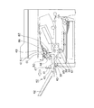
シート検知部の一例である満載検知センサフラグ50には回動中心51に満載検知センサ遮光部53が設けてある。(図1参照)画像形成装置1から排紙トレイ40へとシートが排出積載される場合、シートが所定の高さまで積載される前は、満載検知センサフラグ50に設けられた満載検知センサ遮光部53は満載検知センサ52を遮光している。
The full load
シートが排出される時またはシートが所定の高さまで積載された時は、満載検知センサフラグ50の先端はシート上面に載り回動中心51を中心に回動する。また、シートの排出動作によっても満載検知センサフラグ50は回動し、満載検知センサ遮光部53は満載検知センサ52を遮光しなくなるので、満載検知センサ52は次に遮光されるタイミングを検知してシートが正常に排出されている事を検知する。また、満載検知センサ52は、所定の時間(通常はシート一枚が排出される時間よりも十分長い時間)を超えて連続して
遮光されていない事を検知して、積載部としてのトレイ42上のシート積載高さが定められた上限に達した事を検知し、画像形成装置1は停止する。
When the sheet is discharged or when the sheet is stacked to a predetermined height, the leading end of the full load
なお、本実施形態においては満載検知センサ遮光部53が満載検知センサ52を所定時間遮光しない事を検知して満載状態と判断するようにしたが、満載検知センサ遮光部53が満載検知センサ52を所定時間遮光している事を検知して満載状態と判断するような配置、制御としてもよい。
In this embodiment, the full load detection
(排紙トレイのスライド動作に関する説明)
図1〜図2を用いて、満載検知センサフラグ50の動作について説明するために、シートがB搬送路30内で滞留した場合、および画像形成装置1にシート後処理装置を装着させる場合について説明する。
(Explanation regarding slide operation of the output tray)
In order to explain the operation of the full load
図1に示される排紙トレイ40は、積載壁41、トレイ42、トレイ42の前後側に固定されたレール43、図示しない外装カバー、跳ね上げ部材45等から構成されている。
The
レール43は、排紙トレイ40に棒状のレールとして設けられ、画像形成装置1に入り込んでいる。
The
画像形成装置1のフレームに設けられた軸85,86に対して回動自在な前フレームに設けられたコロ81,82により、レール43が水平方向にスライド自在に排紙トレイ40の重量を支持している。
The
B搬送路30の外側のガイドを構成するFUガイド60は回動中心61を中心として自重で反時計回りに回転する。FUガイド60は、排紙トレイ40に設けられた跳ね上げ部材45がFUガイド60に当接することにより図2のように位置規制されている。
The FU guide 60 constituting the guide on the outside of the
排紙トレイ40には突起47が設けられている。排紙トレイ検知部材46は回動中心を中心に回動自在に設けられて、かつバネで反時計回りに付勢されている。図2に示すように、トレイ42が画像形成装置1の通常動作時に排出されたシートを受け止め、積載可能な第1位置に位置している状態では、突起47が排紙トレイ検知部材46を押圧し、さらに排紙トレイ検知部材46は時計回りに回動して位置検知手段の一例である排紙トレイスイッチ49を押圧し、排紙トレイスイッチ49がON状態になることにより、画像形成装置1はトレイ42が第1位置に位置していることを検知する。
A
図1は排紙トレイ40を引き出した状態を示す。ユーザがB搬送路30に滞留したシートのジャム処理をする場合、把手に手を掛けてトレイ42を第2位置まで左側に引き出し、図1の状態とする。
FIG. 1 shows a state in which the
排紙トレイ40のスライド動作に連動して、跳ね上げ部材45も左側に退避し、FUガイド60が回動中心61を中心に回動することで、B搬送路30が十分に開放されて、B搬送路30内のシートにアクセスが可能となる。
In conjunction with the slide operation of the
このようにトレイ42が引き出された第2位置に位置している状態では、突起47は排紙トレイ検知部材46から離間するので、排紙トレイ検知部材46はバネに付勢されて反時計回りに回動して排紙トレイスイッチ49から離間する。したがって、排紙トレイスイッチ49がOFF状態になるので、画像形成装置1はトレイ42が引き出されて第2位置に位置していることを検知する。
Thus, in the state where the
ユーザがシートのジャム処理を終了すると、ユーザは排紙トレイ40を右側にスライド
させる。跳ね上げ部材45がFUガイド60に当接することで時計回りに回動し、トレイ42が第1位置までスライドするとシートを搬送する状態のB搬送路30を形成する。
When the user finishes the sheet jam processing, the user slides the
これらの構成により排紙トレイ40のスライド動作に連動してB搬送路30が開閉されるので、ユーザはシートのジャム処理を簡単に行うことができる。
With these configurations, the
(満載検知センサフラグの退避動作に関する説明)
図2のようにトレイ42が第1位置に位置している状態では、突起47は排紙トレイ検知部材46を押圧して所定の位置まで回動させている。この時、満載検知センサフラグ50は回動中心51を中心に自重で回転し、所定の待機位置に位置している。満載検知センサ52はフォトセンサを使用している。
(Explanation regarding retraction operation of full load detection sensor flag)
In the state where the
そして、トレイ42上にシートが積載され続けると満載検知センサフラグ50がシート上面に接し、更にシートが所定の上限高さまで積載され続けた時に満載検知センサフラグ50に設けられた満載検知センサ遮光部53が満載検知センサ52を遮光しなくなるので、トレイ42上のシートが積載限度量に達したことを検知する。
When the sheets continue to be stacked on the
トレイ42が画像形成装置1から左側にスライドされて第2位置に位置している状態(図1)では、突起47が排紙トレイ検知部材46から離間し、排紙トレイ検知部材46はバネにより付勢されて所定の位置まで回動する。この時、排紙トレイ検知部材46は満載検知センサフラグ50の回動中心51から枝分かれして伸びる枝部を跳ね上げ、満載検知センサフラグ50は所定の退避位置まで図1の矢印方向に回動する。満載検知センサフラグ50の退避位置は、ジャム処理時にユーザが、画像形成装置1の内部に手を差し込んだ時に、手が満載検知センサフラグ50に触れない位置である。
When the
ユーザがシートのジャム処理を終了すると、ユーザは排紙トレイ40を右側にスライドさせてトレイ42が第1位置に位置すると、突起47は排紙トレイ検知部材46を押圧して所定の位置まで回動させる。排紙トレイ検知部材46は満載検知センサフラグ50の枝部から離間し、満載検知センサフラグ50は自重で所定の待機位置まで戻る。
When the user finishes the sheet jam processing, the user slides the
以上のように、満載検知センサフラグ50の退避位置は、ジャム処理時にユーザが満載検知センサフラグ50に触れない位置であるので、ユーザは満載検知センサフラグ50に邪魔されることなくジャム処理を行うことが出来るので操作性を向上することが可能となる。また、誤って満載検知センサフラグ50を破損することもないので信頼性の向上が可能となる。
As described above, the retraction position of the full load
(シート後処理装置の装着に関する説明)
標準装着されている排紙トレイ40を画像形成装置1から外して、シート後処理装置を装着した場合について説明する。
(Explanation regarding mounting of sheet post-processing device)
A case will be described in which the standardly mounted
図3はシート後処理装置の一例として複数のシートを整合して綴じ処理をすることが可能なステイプルスタッカ200を装着した図である。
FIG. 3 is a diagram illustrating a
まず、排紙トレイ40を最大スライド可能な位置までスライドさせ、画像形成装置1から引き抜き取外す。
First, the
ステイプルスタッカ200には排紙トレイ40に設けられているレール43と同様のレール243が設けられている。また、跳ね上げ部材45と同様の跳ね上げ部材247も設けられており(図4参照)、画像形成装置1に対するインターフェースの構成は排紙トレイ40と同じである。
The
図4のように、ステイプルスタッカ200は、画像形成装置1に接続するインターフェースは排紙トレイ40と全く同じであるため、排紙トレイ40を取外すプロセスとは逆に右側にスライドを行えばステイプルスタッカ200は画像形成装置1に装着可能となる。
As shown in FIG. 4, the
画像形成装置1には突起62が設けられている。ステイプルスタッカ200内には、装着検知手段の一例であるシート後処理装置スイッチ249及びシート後処理装置スイッチ部材246が設けられている。ステイプルスタッカ200が画像形成装置1に装着されていない時は、シート後処理装置スイッチ部材246は時計回りにバネで付勢されている。
The
ステイプルスタッカ200が画像形成装置1に装着されると、突起62がシート後処理装置スイッチ部材246を押圧し、シート後処理装置スイッチ部材246は反時計回りに回動してシート後処理装置スイッチ249はON状態になる。
When the
ステイプルスタッカ200には図示していないケーブルの一端が設けられ、ステイプルスタッカ200が画像形成装置1に装着される時はケーブルのもう一端を画像形成装置1に接続する。ケーブルを介してステイプルスタッカ200と画像形成装置1との電気的な信号の通信が行われる。
The
なお、シート後処理装置の有無検知は、ケーブルが接続された事を検知する手段を設けても良いし、画像形成装置1とステイプルスタッカ200が通信を行った事を検知してシート後処理装置の有無を検知しても良い。
The presence / absence detection of the sheet post-processing apparatus may be provided with a means for detecting that the cable is connected, or the sheet post-processing apparatus by detecting that the
図4のようにステイプルスタッカ200がジャム処理のために左側に引き出された場合でも、ケーブルの一端は画像形成装置1から接続が離れることのない長さに設けられている。
Even when the
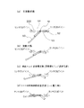
図5の表のように、画像形成装置1、排紙トレイ40及びステイプルスタッカ200の接続状況は6パターンある。排紙トレイスイッチ49がOFF状態、シート後処理装置スイッチ249はON状態及びケーブルを介してステイプルスタッカ200と画像形成装置1と電気的な接続が行われたことを全て検知した時に、ステイプルスタッカ200が正常に画像形成装置1に接続されていることを認識する。
As shown in the table of FIG. 5, there are six patterns of connection states of the
そして、図6のようにステイプルスタッカ200に設けられた図示していない満載検知センサがOFF状態であることを検知した時に、画像形成装置1及びステイプルスタッカ200は正常に動作する。
Then, when it is detected that a full load detection sensor (not shown) provided in the
次に、画像形成装置1からシート後処理装置へシートが進入してきた場合について説明する。
Next, a case where a sheet enters the sheet post-processing apparatus from the
ステイプルスタッカ200には画像形成装置1から排出されたシートを受取り、次の処理作業へとシートを導くシート搬入路202が設けられている。
The
図4のようにシート搬入路202付近にはシート進入検知手段の一例であるシートインセンサ203及びインセンサフラグ205が設けられている。本実施形態ではシートインセンサ203はフォトセンサを用いている。
As shown in FIG. 4, a sheet-in
画像形成装置1から搬送されてきたシートは、ステイプルスタッカ200内部のシート搬入路202に搬入されてインセンサフラグ205と当接し、インセンサフラグ205を回動中心を中心に回動させてシートインセンサ203を遮光し、ステイプルスタッカ200
内にシートが進入した事を検知する。
The sheet conveyed from the
It detects that a seat has entered.
その後、ステイプルスタッカ200はシートインセンサ203からの信号を基に一連の後処理動作を行う。
Thereafter, the
以上のように、トレイ42がシート積載時の第1位置から第2位置に移動すると同時に満載検知センサフラグ50が退避位置まで移動することにより、シート排出口周辺でのジャム処理等の操作を行う時に、満載検知センサフラグ50はジャム処理等の操作の邪魔になることはなく、満載検知センサフラグ50を破損してしまうことを回避することが出来、ユーザビリティ性が高く且つ信頼性の高い装置を提供することが出来る。
As described above, when the
また、本実施形態ではトレイ42の第1位置から第2位置への移動時に対してのみ、満載検知センサフラグ50が移動する構成に関して説明したが、シート後処理装置の着脱によって満載検知センサフラグ50が移動する構成に関しても同様の効果を得ることが出来る。
Further, in the present embodiment, the configuration in which the full load
また、本実施形態では付勢手段によって満載検知センサフラグ50が退避位置まで移動する構成について説明したが、モータ等の電子部品を用いて満載検知センサフラグ50が退避位置まで移動する構成に関しても同様の効果を得ることが出来る。
In the present embodiment, the configuration in which the full load
(実施形態2)
次に、画像形成装置からシート後処理装置へシートが進入してきた場合についての他の実施形態を説明する。なお、上記実施の形態で説明した事項については同符号を付して説明を省略する。本実施の形態では、シート後処理装置にインセンサ用のフラグを設けず、画像形成装置1の満載検知センサフラグ50がシート後処理装置のインセンサ用フラグを兼ねるようにしたものである。
(Embodiment 2)
Next, another embodiment in the case where a sheet enters the sheet post-processing apparatus from the image forming apparatus will be described. Note that the same reference numerals are given to the items described in the above embodiment, and description thereof is omitted. In this embodiment, the sheet post-processing apparatus is not provided with an in-sensor flag, and the full-load
ステイプルスタッカ200には画像形成装置1から排出されたシートを受取り、次の処理作業へとシート導くシート搬入路202が設けられている。
The
図9はステイプルスタッカ200と画像形成装置1の接続部を上面方向から見た断面図である。シート搬入路202付近にはシート進入検知手段の一例であるシートインセンサ203が設けられている。本実施形態ではシートインセンサ203はフォトセンサを用いている。満載検知センサフラグ50には、回動中心51に満載検知センサ遮光部53とインセンサ遮光部54が設けられている。インセンサ遮光部54はシートインセンサ203を遮光するものである(図8(a)〜図8(d)参照)。
FIG. 9 is a cross-sectional view of the connecting portion between the
図7(a)はシート搬入路202にシートSが進入していない状態を示している。この時、満載検知センサフラグ50は所定の待機位置に位置している。この待機位置は満載検知センサフラグ50先端がシート搬入路202を横断し且つシートの搬送の抵抗にならないようにシート搬送方向と略平行位置である。この待機位置は、ステイプルスタッカ200の外装部品に設けられ図示しない突起が排紙トレイ検知部材46に当接し排紙トレイ検知部材46が所定の位置まで回動した時、満載検知センサフラグ50が排紙トレイ検知部材46に当接するまで回動中心51を中心に自重で回動した位置である。この時満載検知センサフラグ50に設けられた満載検知センサ遮光部53が満載検知センサ52を遮光していないので、満載状態と同じ状態になるが、排紙トレイスイッチ49がONされていない事から画像形成装置1は満載検知センサ52からの検知信号を無視する。
FIG. 7A shows a state where the sheet S has not entered the sheet carry-in
図7(b)はシート搬入路202にシートSが進入した状態を示した図である。この時、満載検知センサフラグ50はシートSに押され満載検知センサフラグ50は先端がシー
トSの上面に載る位置まで回動中心51を中心に回動する。
FIG. 7B is a diagram illustrating a state in which the sheet S has entered the sheet carry-in
図8は満載検知センサフラグ50とシートインセンサ203の位置関係を示した図である。満載検知センサフラグ50の回動中心51には満載センサ遮光部53、インセンサ遮光部54が設けてあり、図8(a)は排紙トレイ40上の積載シートが未満載の状態、図8(b)は満載の状態、図8(c)は排紙トレイ40非装着のときの満載検知センサフラグ50の位置を表す。ステイプルスタッカ200を装着したとき満載検知センサフラグ50の回動に従って、インセンサ遮光部54が図8(d)のようにシートインセンサ203を遮光しステイプルスタッカ200内にシートが進入した事を検知する。
FIG. 8 is a diagram showing the positional relationship between the full load
その後、ステイプルスタッカ200はシートインセンサ203からの信号を基に一連の後処理動作を行う。
Thereafter, the
以上のように、シート後処理装置にインセンサ用のフラグを設けることなく、画像形成装置1に設けられている満載検知センサフラグ50がシート後処理装置のインセンサ用フラグを兼ねるために、部品点数が減ることとなるのでコストダウンが可能となり且つ構成が簡略化するので信頼性の高い装置を提供することが出来る。
As described above, the full-load
本実施形態では画像形成装置1の排紙トレイ40が取外された時にシート後処理装置を装着可能な構成について説明したが、排紙トレイ40を取外すことなく画像形成装置1の排紙口にシート後処理装置を装着することが可能な構成の画像形成装置1及びシート後処理装置でも同様の効果を得ることができる。
In the present exemplary embodiment, the configuration in which the sheet post-processing device can be mounted when the
(実施形態3)
次に、画像形成装置1にシート後処理装置を装着し、且つ画像形成装置1側の満載検知センサが画像形成装置1からシート後処理装置へのシート搬入のためのインセンサを兼ねる場合について説明する。なお、上記実施の形態で説明した事項については同符号を付して説明を省略する。
(Embodiment 3)
Next, a case where the sheet post-processing apparatus is mounted on the
図11はステイプルスタッカ200と画像形成装置1の接続部を天面方向から見た断面図である。満載検知センサフラグ50の回動中心51の付近にシート検知手段の一例である満載検知センサ52が設けられている。本実施形態では満載検知センサ52はフォトセンサを用いている。満載検知センサフラグ50には図10に示すように回動中心51に満載検知センサ遮光部53とインセンサ遮光部54が設けられている。満載検知センサ遮光部53とインセンサ遮光部54はどちらも満載検知センサ52を遮光する。
FIG. 11 is a cross-sectional view of the connecting portion between the
図7(a)のように、シートSがステイプルスタッカ200に進入していない場合には、実施形態1で説明した満載検知センサフラグ50は所定の待機位置に位置している。この所定の待機位置は、先端がシート搬入路202を横断する位置である。
As shown in FIG. 7A, when the sheet S does not enter the
図10は満載検知センサフラグ50と満載検知センサ52の位置関係を示した図であり、図10(a)は排紙トレイ40上の積載シートが未満載の状態、図10(b)は満載状態のときの満載検知センサフラグ50の位置を表す。排紙トレイ40非装着時には図10(c)のように満載検知センサ遮光部53は満載検知センサ52を遮光しない位置までしか回動しない。満載検知センサ52は、ステイプルスタッカ200が画像形成装置1に正常に接続されたことが検知された際に、画像形成装置1の排紙トレイ40上のシート枚数を検知するセンサから、ステイプルスタッカ200に搬入されるシートを検知するように制御が切り替わる(図10(d))。
10A and 10B are diagrams showing the positional relationship between the full load
図7(b)のように、満載検知センサフラグ50はステイプルスタッカ200に搬入さ
れてきたシートSに押され、満載検知センサフラグ50の先端がシートSの上面に載る位置まで回動中心51を中心に回動する。従って、図10(d)のようにインセンサ遮光部54は満載検知センサ52を通過し、満載検知センサ52はステイプルスタッカ200にシートが進入したことを検知し、電気信号を図示していないケーブルを介してステイプルスタッカ200に通信する。その後、ステイプルスタッカ200は画像形成装置1からの信号を基に、一連の後処理動作を行う。
As shown in FIG. 7B, the full load
以上のように、シート後処理装置にシートインセンサを設けることなく、画像形成装置1に設けられている満載検知センサ52がシート後処理装置のシートインセンサを兼ねるために、画像形成装置1とシート後処理装置との接続部の構成が簡略化でき、部品点数が減ることとなるのでコストダウンが可能となり且つ構成が簡略化するので信頼性の高い装置を提供することが可能となる。
As described above, since the full-
本実施形態では画像形成装置1の排紙トレイ40がシート積載時の第1の所定位置から第2の所定位置に移動することにより満載検知センサフラグ50が所定の退避位置に移動した後にシート後処理装置を装着可能な構成について説明したが、排紙トレイ40が第2の所定位置に移動することなく画像形成装置1の排紙口にシート後処理装置を装着することが可能な構成の画像形成装置1においてシート後処理装置を装着することにより満載検知センサフラグ50が所定の退避位置に移動する構成でも同様の効果を得ることができる。
In this embodiment, after the
(実施形態4)
また、積載部が折畳まれて第1位置から第2位置への移動する構成でも同様の効果を得ることが出来る。なお、上記実施の形態で説明した事項については同符号を付して説明を省略する。
(Embodiment 4)
Further, the same effect can be obtained even in a configuration in which the stacking unit is folded and moved from the first position to the second position. Note that the same reference numerals are given to the items described in the above embodiment, and description thereof is omitted.
排紙トレイ40の積載部を構成するサブトレイ74、ベーストレイ75、積載壁41が折畳まれて第1位置から第2位置への移動する構成について説明する。図12のようにサブトレイ74は回動中心72を中心に時計回り方向に回動してベーストレイ75上に移動する。次に、ベーストレイ75は回動中心73を中心に時計回り方向に回動して積載壁41前の所定の位置まで移動する。
A configuration in which the sub-tray 74, the
さらに、図13のように折畳まれた状態のサブトレイ74、ベーストレイ75、積載壁41は第1位置から回動中心71を中心に時計回りに回動して所定の第2位置に移動する。この際、突起47が排紙トレイ検知部材46から離間し、排紙トレイ検知部材46はバネにより付勢されて所定の位置まで回動する。この時に満載検知センサフラグ50を跳ね上げ、満載検知センサフラグ50は所定の退避位置まで回動する。満載検知センサフラグ50の退避位置は、ジャム処理時にユーザが、画像形成装置1の内部に手を差し込んだ時に、手が満載検知センサフラグ50に触れない位置である。
Further, the sub-tray 74, the
1 画像形成装置
40 排紙トレイ
49 排紙トレイスイッチ
50 満載検知センサフラグ
52 満載検知センサ
200 ステイプルスタッカ
202 シート搬入路
203 シートインセンサ
249 シート後処理装置スイッチ
DESCRIPTION OF
Claims (9)
前記積載手段に積載されたシートの上面に当接し、積載されたシートの上面位置の変化に伴い移動可能なシート検知部を有し、前記シート検知部の位置を検知することによって前記積載手段に積載されたシートの積載量を検知するシート積載量検知手段と、
装置本体内の搬送路を構成し、下端部を回動中心として回動可能な搬送ガイドと、
を備え、
前記積載手段が前記第2位置へ移動することに伴い、前記搬送ガイドが外側へ回動して前記搬送路が開放されるとともに、前記シート検知部がシート積載量を検知可能な位置から上方に退避し、
さらに、前記シート検知部がシート積載量を検知可能な位置から上方に退避している時、排出されたシートに処理を施すシート後処理装置が前記装置本体に装着可能であることを特徴とする画像形成装置。 A stacking means capable of moving between a first position where an image-formed sheet can be stacked and a second position spaced apart from the first position;
A sheet detector that contacts the top surface of the sheets stacked on the stacking unit and is movable as the upper surface position of the stacked sheets changes, and detects the position of the sheet detection unit to detect the position of the sheet detecting unit. A sheet load amount detection means for detecting the load amount of the stacked sheets;
A conveyance guide that forms a conveyance path in the apparatus main body and is rotatable about the lower end portion as a rotation center;
With
As the stacking unit moves to the second position, the transport guide rotates outward to open the transport path, and the sheet detection unit moves upward from a position where the sheet stacking amount can be detected. Evacuate ,
Further, when the sheet detection unit is retracted upward from a position where the sheet stacking amount can be detected, a sheet post-processing apparatus that performs processing on the discharged sheet can be mounted on the apparatus main body. Image forming apparatus.
前記シート後処理装置が前記装置本体に接続された時、前記シート検知部は前記シート搬入路を横断する待機位置に位置しており、
前記シート搬入路にシートが進入した時、前記シート検知部はシートに押圧されてシート進入検知位置まで移動可能であることを特徴とする請求項1乃至5のいずれか1項に記載の画像形成装置。 The sheet post-processing apparatus is provided with a sheet carry-in path for receiving a sheet discharged from the apparatus main body,
When the sheet post-processing apparatus is connected to the apparatus main body, the sheet detection unit is located at a standby position crossing the sheet carry-in path,
When the sheet enters the sheet carry path, an image forming according to any one of claims 1 to 5, wherein the sheet detecting unit is movable is pressed against the sheet until the sheet enters the detection position apparatus.
Priority Applications (5)
| Application Number | Priority Date | Filing Date | Title |
|---|---|---|---|
| JP2004323235A JP4612829B2 (en) | 2003-12-24 | 2004-11-08 | Image forming apparatus |
| US11/007,314 US7212751B2 (en) | 2003-12-24 | 2004-12-09 | Image forming apparatus |
| CNB2004101048786A CN100402304C (en) | 2003-12-24 | 2004-12-24 | Image forming apparatus |
| US11/670,121 US7526244B2 (en) | 2003-12-24 | 2007-02-01 | Image forming apparatus |
| US12/406,381 US7860412B2 (en) | 2003-12-24 | 2009-03-18 | Image forming apparatus |
Applications Claiming Priority (2)
| Application Number | Priority Date | Filing Date | Title |
|---|---|---|---|
| JP2003426693 | 2003-12-24 | ||
| JP2004323235A JP4612829B2 (en) | 2003-12-24 | 2004-11-08 | Image forming apparatus |
Publications (3)
| Publication Number | Publication Date |
|---|---|
| JP2005206373A JP2005206373A (en) | 2005-08-04 |
| JP2005206373A5 JP2005206373A5 (en) | 2009-10-01 |
| JP4612829B2 true JP4612829B2 (en) | 2011-01-12 |
Family
ID=34703312
Family Applications (1)
| Application Number | Title | Priority Date | Filing Date |
|---|---|---|---|
| JP2004323235A Expired - Fee Related JP4612829B2 (en) | 2003-12-24 | 2004-11-08 | Image forming apparatus |
Country Status (3)
| Country | Link |
|---|---|
| US (3) | US7212751B2 (en) |
| JP (1) | JP4612829B2 (en) |
| CN (1) | CN100402304C (en) |
Families Citing this family (28)
| Publication number | Priority date | Publication date | Assignee | Title |
|---|---|---|---|---|
| JP4612829B2 (en) * | 2003-12-24 | 2011-01-12 | キヤノン株式会社 | Image forming apparatus |
| JP2006293067A (en) * | 2005-04-12 | 2006-10-26 | Canon Inc | Image forming apparatus |
| KR100692572B1 (en) * | 2005-05-30 | 2007-03-13 | 삼성전자주식회사 | Duplex image forming apparatus |
| JP2008152112A (en) * | 2006-12-19 | 2008-07-03 | Canon Inc | Image forming apparatus |
| JP5012601B2 (en) * | 2008-03-18 | 2012-08-29 | セイコーエプソン株式会社 | Recording medium feeding device and recording device |
| JP4609542B2 (en) * | 2008-07-22 | 2011-01-12 | ブラザー工業株式会社 | Image reading apparatus and program |
| US8157259B2 (en) * | 2009-08-04 | 2012-04-17 | Kabushiki Kaisha Toshiba | Movable tray drive control device and movable tray drive control method |
| US20110135364A1 (en) * | 2009-12-04 | 2011-06-09 | Kabushiki Kaisha Toshiba | Image forming apparatus |
| JP5590739B2 (en) * | 2010-11-04 | 2014-09-17 | 京セラドキュメントソリューションズ株式会社 | Recording medium discharging apparatus and image forming apparatus having the same |
| JP5789574B2 (en) | 2012-08-29 | 2015-10-07 | 京セラドキュメントソリューションズ株式会社 | Sheet stacking apparatus and image forming apparatus having the same |
| JP5983253B2 (en) * | 2012-09-28 | 2016-08-31 | ブラザー工業株式会社 | Image forming apparatus |
| JP5512874B1 (en) * | 2012-12-04 | 2014-06-04 | シャープ株式会社 | Processing apparatus and image forming apparatus |
| JP6102399B2 (en) * | 2013-03-26 | 2017-03-29 | セイコーエプソン株式会社 | Recording device |
| JP2014208553A (en) * | 2013-03-27 | 2014-11-06 | セイコーエプソン株式会社 | Recording device |
| JP6213037B2 (en) * | 2013-08-13 | 2017-10-18 | ブラザー工業株式会社 | Image forming apparatus |
| US9815648B2 (en) * | 2015-03-31 | 2017-11-14 | Brother Kogyo Kabushiki Kaisha | Conveyance unit and image recording apparatus |
| WO2017074412A1 (en) | 2015-10-30 | 2017-05-04 | Hewlett-Packard Development Company, L.P. | Sensor apparatus |
| JP6314962B2 (en) * | 2015-11-24 | 2018-04-25 | コニカミノルタ株式会社 | Double-sided image reading apparatus and image forming apparatus |
| JP6836109B2 (en) * | 2016-05-18 | 2021-02-24 | セイコーエプソン株式会社 | Printing device and control method |
| CN111315585B (en) * | 2017-09-01 | 2022-02-22 | 惠普发展公司,有限责任合伙企业 | Method for discharging jammed printing medium, finisher device, and printer device |
| JP7118807B2 (en) * | 2018-08-22 | 2022-08-16 | キヤノン株式会社 | Stacking device and image forming device |
| JP7229718B2 (en) * | 2018-10-19 | 2023-02-28 | キヤノン株式会社 | image forming device |
| US11254536B2 (en) * | 2018-10-19 | 2022-02-22 | Canon Kabushiki Kaisha | Image forming apparatus |
| JP7233879B2 (en) * | 2018-10-19 | 2023-03-07 | キヤノン株式会社 | Sheet conveying device and image forming device |
| JP7224847B2 (en) * | 2018-10-19 | 2023-02-20 | キヤノン株式会社 | image forming device |
| JP7272031B2 (en) * | 2019-03-19 | 2023-05-12 | 株式会社リコー | Paper stacking device, control method and program for paper stacking device |
| JP2021059398A (en) * | 2019-10-03 | 2021-04-15 | 京セラドキュメントソリューションズ株式会社 | Document conveyance device |
| JP2022035688A (en) | 2020-08-21 | 2022-03-04 | シャープ株式会社 | Image forming device |
Citations (5)
| Publication number | Priority date | Publication date | Assignee | Title |
|---|---|---|---|---|
| JPS6311464U (en) * | 1986-07-09 | 1988-01-25 | ||
| JPH11321048A (en) * | 1998-05-16 | 1999-11-24 | Mita Ind Co Ltd | Image formation apparatus |
| JP2000211809A (en) * | 1999-01-18 | 2000-08-02 | Ricoh Co Ltd | Sheet exhausting device of image forming device |
| JP2002249273A (en) * | 2001-02-22 | 2002-09-03 | Canon Inc | Image forming device |
| JP2003228267A (en) * | 2001-11-27 | 2003-08-15 | Sharp Corp | Image forming apparatus |
Family Cites Families (17)
| Publication number | Priority date | Publication date | Assignee | Title |
|---|---|---|---|---|
| US4459019A (en) | 1979-10-25 | 1984-07-10 | Canon Kabushiki Kaisha | Automatic sheet original handling device |
| US5215300A (en) * | 1985-03-15 | 1993-06-01 | Canon Kabushiki Kaisha | Tray apparatus |
| US5280331A (en) | 1990-02-13 | 1994-01-18 | Canon Kabushiki Kaisha | Image forming apparatus with both-surface frame including a retractable re-feeding path unit |
| US5033731A (en) * | 1990-03-12 | 1991-07-23 | Xerox Corporation | Dual mode stack height and sheet delivery detector |
| US5238235A (en) | 1990-08-10 | 1993-08-24 | Canon Kabushiki Kaisha | Sheet feeding apparatus |
| JP2911614B2 (en) | 1990-12-26 | 1999-06-23 | キヤノン株式会社 | Rotation control device and sheet feeding device having rotation control device |
| EP0545707B1 (en) | 1991-12-04 | 1997-09-17 | Canon Kabushiki Kaisha | Delivery member, and apparatus employing the same |
| JP2966243B2 (en) | 1992-07-31 | 1999-10-25 | キヤノン株式会社 | Sheet material feeding device and image forming device |
| JPH06329282A (en) | 1993-05-18 | 1994-11-29 | Canon Inc | Roller |
| JPH0986757A (en) | 1995-09-27 | 1997-03-31 | Tec Corp | Image forming device |
| JP3202568B2 (en) | 1995-12-21 | 2001-08-27 | キヤノンアプテックス株式会社 | Sheet stacking apparatus and image forming apparatus having the same |
| JPH1135226A (en) * | 1997-07-18 | 1999-02-09 | Fujitsu Ltd | Discharged medium detector, medium carrier having the same and image forming device |
| JP2003131450A (en) * | 2001-10-26 | 2003-05-09 | Canon Inc | Image forming device |
| US6882823B2 (en) * | 2002-01-08 | 2005-04-19 | Sharp Kabushiki Kaisha | Image forming system |
| JP3943942B2 (en) | 2002-01-31 | 2007-07-11 | キヤノン株式会社 | Document conveying apparatus, image reading apparatus, and image forming apparatus |
| JP2003307981A (en) * | 2002-02-15 | 2003-10-31 | Sharp Corp | Image forming apparatus |
| JP4612829B2 (en) | 2003-12-24 | 2011-01-12 | キヤノン株式会社 | Image forming apparatus |
-
2004
- 2004-11-08 JP JP2004323235A patent/JP4612829B2/en not_active Expired - Fee Related
- 2004-12-09 US US11/007,314 patent/US7212751B2/en active Active
- 2004-12-24 CN CNB2004101048786A patent/CN100402304C/en not_active Expired - Fee Related
-
2007
- 2007-02-01 US US11/670,121 patent/US7526244B2/en not_active Expired - Fee Related
-
2009
- 2009-03-18 US US12/406,381 patent/US7860412B2/en not_active Expired - Fee Related
Patent Citations (5)
| Publication number | Priority date | Publication date | Assignee | Title |
|---|---|---|---|---|
| JPS6311464U (en) * | 1986-07-09 | 1988-01-25 | ||
| JPH11321048A (en) * | 1998-05-16 | 1999-11-24 | Mita Ind Co Ltd | Image formation apparatus |
| JP2000211809A (en) * | 1999-01-18 | 2000-08-02 | Ricoh Co Ltd | Sheet exhausting device of image forming device |
| JP2002249273A (en) * | 2001-02-22 | 2002-09-03 | Canon Inc | Image forming device |
| JP2003228267A (en) * | 2001-11-27 | 2003-08-15 | Sharp Corp | Image forming apparatus |
Also Published As
| Publication number | Publication date |
|---|---|
| US20070126174A1 (en) | 2007-06-07 |
| US7212751B2 (en) | 2007-05-01 |
| CN100402304C (en) | 2008-07-16 |
| JP2005206373A (en) | 2005-08-04 |
| US20090185812A1 (en) | 2009-07-23 |
| CN1636751A (en) | 2005-07-13 |
| US7860412B2 (en) | 2010-12-28 |
| US7526244B2 (en) | 2009-04-28 |
| US20050141939A1 (en) | 2005-06-30 |
Similar Documents
| Publication | Publication Date | Title |
|---|---|---|
| JP4612829B2 (en) | Image forming apparatus | |
| JP3685994B2 (en) | Sheet post-processing device | |
| JP4516894B2 (en) | Automatic document feeder, image forming apparatus having the same, and image reading apparatus | |
| US20020159805A1 (en) | Image forming apparatus | |
| JP2010241598A (en) | Paper sheet stacking device and image forming device | |
| US20090074495A1 (en) | Compact image forming apparatus with post-processing | |
| JP5112182B2 (en) | Automatic document feeder | |
| US20050238397A1 (en) | Image forming apparatus | |
| EP2910505B1 (en) | Sheet loader, image forming apparatus incorporating the sheet loader, and image reader incorporating the sheet loader | |
| JP5538453B2 (en) | Post-processing apparatus and image forming apparatus | |
| JP2009175485A (en) | Image forming apparatus | |
| JP7083449B2 (en) | Sheet transfer device, image reader and image forming device | |
| JP4564812B2 (en) | Sheet stacking apparatus and image forming apparatus provided with the apparatus | |
| JP6565346B2 (en) | Document conveying apparatus, image reading apparatus, and image forming apparatus | |
| JP2011116478A (en) | Image forming apparatus | |
| JP4227473B2 (en) | Image forming apparatus | |
| JP7224847B2 (en) | image forming device | |
| JP5709798B2 (en) | Post-processing apparatus and image forming apparatus | |
| JP7086526B2 (en) | Sheet transfer device, image forming device, and image reading device | |
| JP4402385B2 (en) | Image forming apparatus with sheet post-processing device | |
| JP3754049B2 (en) | Image forming apparatus | |
| JP2024010443A (en) | Image forming apparatus | |
| JP5748703B2 (en) | Post-processing apparatus and image forming apparatus | |
| JP2021123461A (en) | Sheet feeder, sheet reader comprising sheet feeder, and image forming apparatus comprising sheet reader | |
| JP2005212992A (en) | Paper processing device and image forming system |
Legal Events
| Date | Code | Title | Description |
|---|---|---|---|
| A621 | Written request for application examination |
Free format text: JAPANESE INTERMEDIATE CODE: A621 Effective date: 20071107 |
|
| A521 | Request for written amendment filed |
Free format text: JAPANESE INTERMEDIATE CODE: A523 Effective date: 20090819 |
|
| A977 | Report on retrieval |
Free format text: JAPANESE INTERMEDIATE CODE: A971007 Effective date: 20091225 |
|
| A131 | Notification of reasons for refusal |
Free format text: JAPANESE INTERMEDIATE CODE: A131 Effective date: 20100323 |
|
| A521 | Request for written amendment filed |
Free format text: JAPANESE INTERMEDIATE CODE: A523 Effective date: 20100524 |
|
| A131 | Notification of reasons for refusal |
Free format text: JAPANESE INTERMEDIATE CODE: A131 Effective date: 20100720 |
|
| A521 | Request for written amendment filed |
Free format text: JAPANESE INTERMEDIATE CODE: A523 Effective date: 20100916 |
|
| TRDD | Decision of grant or rejection written | ||
| A01 | Written decision to grant a patent or to grant a registration (utility model) |
Free format text: JAPANESE INTERMEDIATE CODE: A01 Effective date: 20101005 |
|
| A01 | Written decision to grant a patent or to grant a registration (utility model) |
Free format text: JAPANESE INTERMEDIATE CODE: A01 |
|
| A61 | First payment of annual fees (during grant procedure) |
Free format text: JAPANESE INTERMEDIATE CODE: A61 Effective date: 20101016 |
|
| FPAY | Renewal fee payment (event date is renewal date of database) |
Free format text: PAYMENT UNTIL: 20131022 Year of fee payment: 3 |
|
| R150 | Certificate of patent or registration of utility model |
Ref document number: 4612829 Country of ref document: JP Free format text: JAPANESE INTERMEDIATE CODE: R150 Free format text: JAPANESE INTERMEDIATE CODE: R150 |
|
| LAPS | Cancellation because of no payment of annual fees |