JP4609352B2 - Power supply - Google Patents
Power supply Download PDFInfo
- Publication number
- JP4609352B2 JP4609352B2 JP2006076737A JP2006076737A JP4609352B2 JP 4609352 B2 JP4609352 B2 JP 4609352B2 JP 2006076737 A JP2006076737 A JP 2006076737A JP 2006076737 A JP2006076737 A JP 2006076737A JP 4609352 B2 JP4609352 B2 JP 4609352B2
- Authority
- JP
- Japan
- Prior art keywords
- secondary battery
- charging
- resistor
- lithium ion
- ion secondary
- Prior art date
- Legal status (The legal status is an assumption and is not a legal conclusion. Google has not performed a legal analysis and makes no representation as to the accuracy of the status listed.)
- Expired - Fee Related
Links
Images


Classifications
-
- Y—GENERAL TAGGING OF NEW TECHNOLOGICAL DEVELOPMENTS; GENERAL TAGGING OF CROSS-SECTIONAL TECHNOLOGIES SPANNING OVER SEVERAL SECTIONS OF THE IPC; TECHNICAL SUBJECTS COVERED BY FORMER USPC CROSS-REFERENCE ART COLLECTIONS [XRACs] AND DIGESTS
- Y02—TECHNOLOGIES OR APPLICATIONS FOR MITIGATION OR ADAPTATION AGAINST CLIMATE CHANGE
- Y02E—REDUCTION OF GREENHOUSE GAS [GHG] EMISSIONS, RELATED TO ENERGY GENERATION, TRANSMISSION OR DISTRIBUTION
- Y02E60/00—Enabling technologies; Technologies with a potential or indirect contribution to GHG emissions mitigation
- Y02E60/10—Energy storage using batteries
-
- Y—GENERAL TAGGING OF NEW TECHNOLOGICAL DEVELOPMENTS; GENERAL TAGGING OF CROSS-SECTIONAL TECHNOLOGIES SPANNING OVER SEVERAL SECTIONS OF THE IPC; TECHNICAL SUBJECTS COVERED BY FORMER USPC CROSS-REFERENCE ART COLLECTIONS [XRACs] AND DIGESTS
- Y02—TECHNOLOGIES OR APPLICATIONS FOR MITIGATION OR ADAPTATION AGAINST CLIMATE CHANGE
- Y02P—CLIMATE CHANGE MITIGATION TECHNOLOGIES IN THE PRODUCTION OR PROCESSING OF GOODS
- Y02P70/00—Climate change mitigation technologies in the production process for final industrial or consumer products
- Y02P70/50—Manufacturing or production processes characterised by the final manufactured product
Description
本発明は、電源に関する。 The present invention relates to a power source.
近年のさまざまな携帯型機器の普及及び発展に伴い、リチウムイオン二次電池等の二次電池を用いた電源のさらなる低コスト化および特性向上が望まれている。このような電源において向上が期待される特性の一つとして急速充電特性がある。二次電池の従来の充電方法としては、主として、定電流充電法、定電流・定電圧充電法、及び定電圧充電法がある(特許文献1〜4参照)。 With the spread and development of various portable devices in recent years, further cost reduction and improvement in characteristics of a power source using a secondary battery such as a lithium ion secondary battery are desired. One of the characteristics expected to be improved in such a power supply is a quick charge characteristic. Conventional charging methods for secondary batteries mainly include a constant current charging method, a constant current / constant voltage charging method, and a constant voltage charging method (see Patent Documents 1 to 4).
定電流充電法は、一定の充電電流となるように充電電圧を制御し充電電圧が予め定められた満充電電圧(例えば4.2V)となると二次電池への充電を停止する方法である。定電流充電法では、充電電圧が満充電電圧に近くなるとIRドロップや分極による影響で充電効率が悪くなるため、充電量が不足しやすい。特に、急速充電を行うとこの傾向が顕著である。また、このような定電流充電法を用いた場合に、充電量を補うべく、さらに、満充電電圧に達した後にこの満充電電圧よりも高い電圧まで定電流充電を行った場合、二次電池の正極や負極内で部分的に過充電状態となり、電解質の分解やガス発生を生じる問題がある。 The constant current charging method is a method in which the charging voltage is controlled so that a constant charging current is obtained, and charging to the secondary battery is stopped when the charging voltage reaches a predetermined full charging voltage (for example, 4.2 V). In the constant current charging method, when the charging voltage is close to the full charging voltage, the charging efficiency is deteriorated due to the influence of IR drop or polarization, so that the amount of charging is likely to be insufficient. This tendency is particularly noticeable when rapid charging is performed. Further, when such a constant current charging method is used, in order to compensate for the charge amount, and when the constant current charging is performed to a voltage higher than the full charge voltage after reaching the full charge voltage, the secondary battery There is a problem that the battery is partially overcharged in the positive electrode and the negative electrode, causing electrolyte decomposition and gas generation.
一方、リチウムイオン二次電池の充電に通常用いられている定電流・定電圧充電法は、充電電圧が満充電電圧になるまで定電流充電を行った後、この満充電電圧による定電圧充電に切り替え、充電電流が所定値以下になると充電を終了する。これによれば定電流充電に比べて充電量不足を解消しやすいものの、充電装置の回路が複雑となりコスト高の原因となる。 On the other hand, the constant current / constant voltage charging method, which is usually used for charging lithium ion secondary batteries, performs constant current charging until the charging voltage reaches the full charge voltage, and then performs constant voltage charging with this full charge voltage. Switching is completed when the charging current becomes equal to or lower than a predetermined value. According to this, although it is easy to solve the shortage of charge compared to the constant current charge, the circuit of the charging device becomes complicated and causes high costs.
一方、定電圧充電法は、一定の充電電圧を二次電池に供給する方法であり、充電電圧を適切に設定することにより二次電池を過充電状態にさせる心配がなく、さらに、適切な充電時間や充電停止電流値を設定することにより、十分な充電量を得ることができ、急速充電も可能である。また、定電流・定電圧充電に比べて充電装置の回路が単純となりコスト低下が期待できる。
しかしながら、定電圧充電法を行うと、充電初期に非常に大きな充電電流が二次電池に流れる。発明者らが検討したところ、このような大きな充電電流が生じると、充電装置自体が大きく発熱して安全性の点で不都合が生じる場合がある。さらに、このような充電電流が二次電池に流れると、二次電池のカソードやアノード上において電気化学的反応の不均一性が増大し、部分的な過充電状態やこれに伴う電解質の分解等が生ずる。また、リチウムイオン二次電池においては、アノード上にリチウムイオン等のイオンが完全にインターカレートしなくなるという問題が発生する。例えば、リチウムイオンが完全にアノード上にインターカレートしない場合には、リチウムのデンドライト析出が生じ、充放電サイクルの経過に伴う大きな容量劣化及び内部短絡を引き起こす原因となる。 However, when the constant voltage charging method is performed, a very large charging current flows in the secondary battery in the initial stage of charging. As a result of investigations by the inventors, when such a large charging current is generated, the charging device itself generates a large amount of heat, which may cause inconvenience in terms of safety. Furthermore, when such a charging current flows through the secondary battery, the non-uniformity of the electrochemical reaction on the cathode or anode of the secondary battery increases, resulting in a partial overcharge state and accompanying electrolyte decomposition. Will occur. Further, in the lithium ion secondary battery, there arises a problem that ions such as lithium ions are not completely intercalated on the anode. For example, when lithium ions do not completely intercalate on the anode, lithium dendrite precipitation occurs, causing a large capacity deterioration and internal short circuit with the progress of the charge / discharge cycle.
本発明は上記課題に鑑みてなされたものであり、定電圧充電法を行った場合でも、充電初期において二次電池に流れる充電電流を抑制できる電源を提供することを目的とする。 The present invention has been made in view of the above problems, and an object of the present invention is to provide a power source capable of suppressing a charging current flowing in a secondary battery in the initial stage of charging even when a constant voltage charging method is performed.
本発明に係る電源は、一対の電極を有する二次電池と、一対の電極の少なくとも一極性側の電極に電気的に接続されたリボン状のリードと、を備える。リードは、電極に接続されたリボン状の内側導電部、リボン状の抵抗体、及び、リボン状の外側導電部を有し、内側導電部の側面と抵抗体の一側面とが接合され、外側導電部の側面と抵抗体の他側面とが接合されており、抵抗体は、チタン、ステンレス、ニッケル銅合金、ニッケルクロム合金、又は、銅マンガン合金製である。 A power supply according to the present invention includes a secondary battery having a pair of electrodes and a ribbon-like lead electrically connected to an electrode on at least one polarity side of the pair of electrodes. The lead has a ribbon-shaped inner conductive portion connected to the electrode, a ribbon-shaped resistor, and a ribbon-shaped outer conductive portion, and the side surface of the inner conductive portion and one side surface of the resistor are joined to each other. side surface of the conductive portion and are with the other side of the resistor is joined, the resistor, titanium, stainless steel, nickel copper alloys, nickel-chromium alloys, or Ru der made of a copper-manganese alloy.
本発明によれば、定電圧発生手段からの定電圧の印加により二次電池を充電する際に、二次電池と定電圧発生手段との間に抵抗体が介在する。したがって、充電初期において二次電池へ流れる充電電流が比較的大きい場合には、抵抗体の抵抗による電圧降下によって、抵抗体が無い場合に比して二次電池に印加される電圧が低くなって充電電流が抑制される。一方、充電終期において二次電池への充電電流が少なくなると、抵抗体の抵抗による電圧降下は少なくなり、二次電池に定電圧発生手段からの電圧が十分に印加されて十分な充電が行われる。 According to the present invention, when the secondary battery is charged by applying a constant voltage from the constant voltage generating means, the resistor is interposed between the secondary battery and the constant voltage generating means. Therefore, when the charging current flowing to the secondary battery is relatively large at the initial stage of charging, the voltage applied to the secondary battery is lower than that without the resistor due to the voltage drop due to the resistance of the resistor. The charging current is suppressed. On the other hand, when the charging current to the secondary battery is reduced at the end of charging, the voltage drop due to the resistance of the resistor is reduced, and the secondary battery is sufficiently charged with the voltage from the constant voltage generating means being sufficiently applied. .
ここで、抵抗体の一側面と抵抗体の他側面とが対向していることが好ましい。
リードの幅は、内側導電部、抵抗体及び外側導電部に亘って一定であることも好ましい。
Here, it is preferable that one side surface of the resistor and the other side surface of the resistor face each other.
It is also preferable that the width of the lead is constant over the inner conductive portion, the resistor, and the outer conductive portion.
また、二次電池は、複数の二次電池要素が並列に接続されたものであることが好ましい。この場合には、容量の大きな電源を容易に得られる。 In addition, the secondary battery is preferably one in which a plurality of secondary battery elements are connected in parallel. In this case, a power source having a large capacity can be easily obtained.
また、抵抗体の抵抗値は、二次電池の直流内部抵抗値の1.5〜25倍の抵抗値であることが好ましい。 In addition, the resistance value of the resistor is preferably 1.5 to 25 times the DC internal resistance value of the secondary battery.
この条件を満たすと、充電の際の二次電池への電流値を概ね50〜5Cに抑制することができる。ここで、二次電池の直流内部抵抗値は、1C〜10Cにて二次電池に直流電流を10秒間通電し、その電圧降下を測定し、電流値と電圧降下との関係から算出した値である。 When this condition is satisfied, the current value to the secondary battery during charging can be suppressed to approximately 50 to 5C. Here, the DC internal resistance value of the secondary battery is a value calculated from the relationship between the current value and the voltage drop by applying a DC current to the secondary battery for 10 seconds at 1C to 10C, measuring the voltage drop. is there.
また、この電源は、二次電池を収容する外装体と、一端が外装体内に配置されて二次電池の一極性側の電極と電気的に接続され、他端が外装体の外に突出する第一リード線と、一端が外装体内に配置されて二次電池の他極性側の電極と電気的に接続され他端が外装体の外に突出する第二リード線と、を備え、抵抗体は、第一リード線及び第二リード線の内の少なくとも一方のリード線の途中に接続されていることが好ましい。 In addition, the power source includes an exterior body that houses the secondary battery, one end disposed in the exterior body, and electrically connected to the electrode on the one-polar side of the secondary battery, and the other end protruding outside the exterior body. A first lead wire, and a second lead wire, one end of which is disposed in the exterior body and electrically connected to an electrode on the other polarity side of the secondary battery, and the other end projects out of the exterior body. Is preferably connected in the middle of at least one of the first lead wire and the second lead wire.
このような電源は、製造容易であり、また、取り扱いが容易である。 Such a power supply is easy to manufacture and easy to handle.
ここで、抵抗体が、リード線において外装体内に収容された部分の途中に接続されていると、リード線において外部に露出する部分は従来の電源と同様となるので、リード線と外部負荷や充電装置との接続が容易である。 Here, if the resistor is connected in the middle of the portion of the lead wire housed in the exterior body, the exposed portion of the lead wire is the same as that of the conventional power supply, so the lead wire and the external load or Connection with the charging device is easy.
一方、抵抗体が、リード線において外装体の外に露出された部分の途中に接続されていると、リード線の端部(外側部)を利用して抵抗体を介在させて二次電池を充電させることができる一方、抵抗体を挟んで端部と反対側のリード線の内側部を利用して抵抗体を介さずに二次電池を放電させることができる。 On the other hand, if the resistor is connected in the middle of the portion of the lead wire that is exposed outside the exterior body, the secondary battery is formed by interposing the resistor using the end portion (outer portion) of the lead wire. While the battery can be charged, the secondary battery can be discharged without using the inner side of the lead wire on the side opposite to the end portion with the resistor interposed therebetween without using the resistor.
また、具体的には、抵抗体はニッケル銅や銅マンガン等の合金系や、導電性ポリマー等の材料から形成されることができる。 Specifically, the resistor can be made of an alloy system such as nickel copper or copper manganese, or a material such as a conductive polymer.
また、二次電池としては、リチウムイオン二次電池が好適である。 Moreover, a lithium ion secondary battery is suitable as the secondary battery.
本発明によれば、定電圧充電法を行った場合でも、充電初期に二次電池要素に流れる電流を抑制できる電源が提供される。 ADVANTAGE OF THE INVENTION According to this invention, even when a constant voltage charging method is performed, the power supply which can suppress the electric current which flows into a secondary battery element in the charge initial stage is provided.
以下、図面を参照しながら本発明の好適な実施形態について詳細に説明する。なお、以下の説明では、同一又は相当部分には同一符号を付し、重複する説明は省略する。 Hereinafter, preferred embodiments of the present invention will be described in detail with reference to the drawings. In the following description, the same or corresponding parts are denoted by the same reference numerals, and redundant description is omitted.
(第一実施形態)
まず、本発明のリチウムイオン二次電池を備える電源の実施形態について詳細に説明する。
(First embodiment)
First, an embodiment of a power source including the lithium ion secondary battery of the present invention will be described in detail.
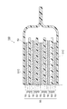
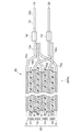
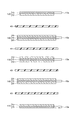
図1は本発明の第一実施形態に係る電源100を示す部分破断斜視図である。また、図2は図1のYZ面断面図である。図3は、図1のリチウムイオン二次電池85、リード線12及びリード線22のZX断面矢視図である。
FIG. 1 is a partially broken perspective view showing a
本実施形態に係る電源100は、図1〜図3に示すように、主として、リチウムイオン二次電池85と、リチウムイオン二次電池85を密閉した状態で収容するケース(外装体)50と、リチウムイオン二次電池85とケース50の外部とを接続するためのリード線12及びリード線22とから構成されている。リチウムイオン二次電池85は、上から順に、集電体15、リチウムイオン二次電池要素(二次電池要素)61、集電体16、リチウムイオン二次電池要素(二次電池要素)62、集電体15、リチウムイオン二次電池要素(二次電池要素)63、集電体16、リチウムイオン二次電池要素(二次電池要素)64、及び、集電体15を有しており、各二次電池要素61〜64が並列に接続されて一つの二次電池を構成している。
As shown in FIGS. 1 to 3, the
(リチウムイオン二次電池要素)
リチウムイオン二次電池要素61,62,63,64は、図2に示すように、それぞれ、互いに対向する板状のカソード(電極)10及び板状のアノード(電極)20と、カソード10とアノード20との間に隣接して配置される板状の電気絶縁性のセパレータ40と、電解質を含みカソード10、アノード20、及び、セパレータ40中に含有された電解質溶液(図示せず)と、から各々構成されている。
(Lithium ion secondary battery element)
As shown in FIG. 2, the lithium ion
そして、集電体16にはアノード20が接触し、集電体15にはカソード10が接触するようにして、リチウムイオン二次電池要素61〜64は積層されている。ここでアノード及びカソードは説明の便宜上、リチウムイオン二次電池85の放電時の極性を基準に決定したものである。リチウムイオン二次電池85の充電時においては電荷の流れる方向が放電時の逆になるため、アノード及びカソードが互いに入れ替わる。
The lithium ion
(アノード)
アノード20は、アノード活物質、導電助剤、結着剤等を含む層である。以下アノード20について説明する。
(anode)
The
アノード活物質は、リチウムイオンの吸蔵及び放出、リチウムイオンの脱離及び挿入、又は、リチウムイオンと、そのリチウムイオンのカウンターアニオン(例えば、ClO4 −)とのドープ及び脱ドープを可逆的に進行させることができれば特に限定されず、公知のリチウムイオン二次電池要素に用いられているものと同様の材料を使用することができる。例えば、天然黒鉛、人造黒鉛、メソカーボンマイクロビーズ、メソカーボンファイバー、コークス類、ガラス状炭素、有機化合物焼成体等の炭素材料、Al、Si、Sn等のリチウムと化合することのできる金属、SiO2、SnO2等の酸化物を主体とする非晶質の化合物、チタン酸リチウム(Li4Ti5O12)が挙げられる。 The anode active material reversibly advances the insertion and removal of lithium ions, the desorption and insertion of lithium ions, or the doping and dedoping of lithium ions and their counter anions (for example, ClO 4 − ). If it can be made, it will not specifically limit, The material similar to what is used for a well-known lithium ion secondary battery element can be used. For example, natural graphite, artificial graphite, mesocarbon microbeads, mesocarbon fibers, cokes, glassy carbon, carbon materials such as organic compound fired bodies, metals that can be combined with lithium such as Al, Si, Sn, SiO 2 and amorphous compounds mainly composed of oxides such as SnO 2 and lithium titanate (Li 4 Ti 5 O 12 ).
中でも、炭素材料が好ましく、炭素材料の層間距離d002が0.335〜0.338nmであり、かつ、炭素材料の結晶子の大きさLc002が30〜120nmであるものがより好ましい。このような条件を満たす炭素材料としては、人造黒鉛、MCF(メソカーボンファイバー)等が挙げられる。なお、上記層間距離d002及び結晶子の大きさLc002は、X線回折法により求めることができる。 Among these, a carbon material is preferable, and an interlayer distance d 002 of the carbon material is 0.335 to 0.338 nm, and a crystallite size Lc 002 of the carbon material is more preferably 30 to 120 nm. Examples of the carbon material satisfying such conditions include artificial graphite and MCF (mesocarbon fiber). The size Lc 002 of the interlayer distance d 002 and crystallite can be determined by X-ray diffraction method.
導電助剤は、アノード20の導電性を良好にするものであれば特に限定されず、公知の導電助剤を使用できる。例えば、カーボンブラック類、炭素材料、銅、ニッケル、ステンレス、鉄等の金属微粉、炭素材料及び金属微粉の混合物、ITO等の導電性酸化物が挙げら
れる。
The conductive aid is not particularly limited as long as the conductivity of the
結着剤は、上記のアノード活物質の粒子と導電助剤の粒子とを集電体16に結着することができれば特に限定されず、公知の結着剤を使用できる。例えば、ポリフッ化ビニリデン(PVDF)、ポリテトラフルオロエチレン(PTFE)、テトラフルオロエチレン−ヘキサフルオロプロピレン共重合体(FEP)、テトラフルオロエチレン−パーフルオロアルキルビニルエーテル共重合体(PEA)、エチレン−テトラフルオロエチレン共重合体(ETFE)、ポリクロロトリフルオロエチレン(PCTFE)、エチレン−クロロトリフルオロエチレン共重合体(ECTFE)、ポリフッ化ビニル(PVF)等のフッ素樹脂及びスチレン−ブタジエンゴム(SBR)等が挙げられる。
The binder is not particularly limited as long as it can bind the anode active material particles and the conductive auxiliary particles to the
アノード20と結着する集電体16の材料はリチウムイオン二次電池要素のアノード用集電体として通常使用される金属材料であれば特に限定されず、例えば、銅やニッケル等が挙げられる。集電体16の端には、図1及び図3に示すように、各集電体がそれぞれ外側に向かって延びてなる舌状部16aが形成されている。各舌状部16aは一つに束ねられて後述するリード線22に電気的に接続されている。
The material of the
(カソード)
カソード10は、カソード活物質、導電助剤、結着剤等を含む層である。以下カソード10について説明する。
(Cathode)
The
カソード活物質は、リチウムイオンの吸蔵及び放出、リチウムイオンの脱離及び挿入(インターカレーション)、又は、リチウムイオンと、そのリチウムイオンのカウンターアニオン(例えば、ClO4 −)とのドープ及び脱ドープを可逆的に進行させることが可能
であれば特に限定されず、公知の電極活物質を使用できる。例えば、コバルト酸リチウム(LiCoO2)、ニッケル酸リチウム(LiNiO2)、リチウムマンガンスピネル(LiMn2O4)、及び、一般式:LiNixCoyMnzO2(x+y+z=1)で表される複合金属酸化物、リチウムバナジウム化合物(LiV2O5)、オリビン型LiMPO4(ただし、Mは、Co、Ni、Mn又はFeを示す)、チタン酸リチウム(Li4Ti5O12)等の複合金属酸化物が挙げられる。
The cathode active material is occlusion and release of lithium ions, desorption and insertion (intercalation) of lithium ions, or doping and dedoping of lithium ions and counterions (eg ClO 4 − ) of the lithium ions. The electrode is not particularly limited as long as it can be reversibly advanced, and a known electrode active material can be used. For example, lithium cobalt oxide (LiCoO 2), lithium nickel oxide (LiNiO 2), lithium manganese spinel (LiMn 2 O 4), and the general formula: represented by LiNi x Co y Mn z O 2 (x + y + z = 1) Composite metal oxide, lithium vanadium compound (LiV 2 O 5 ), olivine type LiMPO 4 (where M represents Co, Ni, Mn or Fe), composite such as lithium titanate (Li 4 Ti 5 O 12 ) A metal oxide is mentioned.
カソード10に含まれるカソード活物質以外の各構成要素は、アノード20を構成するものと同様の物質を使用することができる。また、カソード10においても、アノード20と同様の電子伝導性の粒子を含有させることが好ましい。
As each component other than the cathode active material included in the
カソード10と結着する集電体15はリチウムイオン二次電池要素のカソード用集電体として通常用いられる金属材料であれば特に限定されず、例えばアルミニウム等が挙げられる。集電体15の端には、図1及び図3に示すように、各集電体がそれぞれ外側に向かって延びてなる舌状部15aが形成されている。各舌状部15aは一つに束ねられて後述するリード線12の内側部12aに電気的に接続されている。したがって、リチウムイオン二次電池85は、リチウムイオン二次電池要素61,62,63,64が並列に接続された二次電池となる。
The
(セパレータ)
アノード20とカソード10との間に配置されるセパレータ40は、電気絶縁性の多孔体から形成されていれば特に限定されず、公知のリチウムイオン二次電池要素に用いられているセパレータを使用することができる。例えば、電気絶縁性の多孔体としては、ポリエチレン、ポリプロピレン又はポリオレフィンからなるフィルムの積層体や上記樹脂の混合物の延伸膜、或いは、セルロース、ポリエステル及びポリプロピレンからなる群より選択される少なくとも1種の構成材料からなる繊維不織布が挙げられる。
(Separator)
The
ここで、図3に示すように、各二次電池要素要素61〜64について、セパレータ40、アノード20、カソード10の順に面積が小さくなっており、アノード20の端面はカソード10の端面よりも外側に突出し、セパレータ40の端面はアノード20及びカソード10の端面よりも外側に突出するようになっている。
Here, as shown in FIG. 3, the areas of the secondary
これによって、製造時の誤差等によって、各層が積層方向と交差する方向に多少位置ずれを起こした場合でも、各リチウムイオン二次電池要素61〜64において、カソード10の全面をアノード20に対向させることが容易となる。従って、カソード10から放出されたリチウムイオンがセパレータ40を介してアノード20に十分に取り込まれる。リチウムイオンがアノード20に十分に取り込まれない場合には、アノード20に取り込まれなかったリチウムイオンが析出して電気エネルギーのキャリアが減少するため、電池のエネルギー容量が劣化する場合がある。さらに、セパレータ40がカソード10やアノード20より大きく、カソード10やアノード20の端面から突出しているので、カソード10とアノード20とが接触することによる短絡も低減されている。
Thus, even when each layer is slightly displaced in the direction intersecting the stacking direction due to an error in manufacturing, the entire surface of the
(電解質溶液)
電解質溶液は、アノード20及びカソード10、及びセパレータ40の孔の内部に含有されている。電解質溶液は、特に限定されず、公知のリチウムイオン二次電池要素に用いられている電解質溶液(電解質水溶液、有機溶媒を使用する電解質溶液)を使用することができる。ただし、電解質水溶液は電気化学的に分解電圧が低いことにより、充電時の耐用電圧が低く制限されるので、有機溶媒を使用する電解質溶液(非水電解質溶液)であることが好ましい。リチウムイオン二次電池要素の電解質溶液としては、リチウム塩を非水溶媒(有機溶媒)に溶解したものが好適に使用される。リチウム塩としては、例えば、LiPF6、LiClO4、LiBF4、LiAsF6、LiCF3SO3、LiCF3、CF2SO3、LiC(CF3SO2)3、LiN(CF3SO2)2、LiN(CF3CF2SO2)2、LiN(CF3SO2)(C4F9SO2)、LiN(CF3CF2CO)2等の塩が使用される。なお、これらの塩は1種を単独で使用してもよく、2種以上を併用してもよい。
(Electrolyte solution)
The electrolyte solution is contained inside the
また、有機溶媒としては、公知のリチウムイオン二次電池要素に使用されている溶媒を使用することができる。例えば、プロピレンカーボネート、エチレンカーボネート、及び、ジエチルカーボネート等が好ましく挙げられる。これらは単独で使用してもよく、2種以上を任意の割合で混合して使用してもよい。 Moreover, as an organic solvent, the solvent currently used for the well-known lithium ion secondary battery element can be used. For example, propylene carbonate, ethylene carbonate, diethyl carbonate and the like are preferable. These may be used alone or in combination of two or more at any ratio.
なお、本実施形態において、電解質溶液は液状以外にゲル化剤を添加することにより得られるゲル状電解質であってもよい。また、電解質溶液に代えて、固体電解質(固体高分子電解質又はイオン伝導性無機材料からなる電解質)が含有されていてもよい。 In the present embodiment, the electrolyte solution may be a gel electrolyte obtained by adding a gelling agent in addition to liquid. Further, instead of the electrolyte solution, a solid electrolyte (a solid polymer electrolyte or an electrolyte made of an ion conductive inorganic material) may be contained.
(リード線、抵抗体)
リード線12(第一リード線)及びリード線(第二リード線)22は、図1に示すように、リボン状の外形を呈してケース50内からシール部50bを通って外部に突出している。そして、リード線12の途中には、抵抗体13が接続されている。
(Lead wire, resistor)
As shown in FIG. 1, the lead wire 12 (first lead wire) and the lead wire (second lead wire) 22 have a ribbon-like outer shape and project outside from the
具体的には、リード線12は、抵抗体13よりもケース50側の内側部12aと、抵抗体13を挟んでケース50とは反対側にある外側部12bとを有しており、内側部12aと外側部12bとの間に抵抗体13が接続されている。
Specifically, the
内側部12aは、ケース50の内側からケース50のシール部50bを通ってケース50の外側まで延びており、金属等の導体材料より形成されている。内側部12aにおけるリチウムイオン二次電池85に近い部分の端部は、図3に示すように、各集電体15,15,15の各舌状部15a、15a,15aと抵抗溶接等によって接合されており、この内側部12aは各集電体15を介して各カソード10と電気的に接続されている。また、内側部12aにおいてケース50のシール部50bに挟まれる部分は、図1及び図3に示すように、シール性を高めるべく、樹脂等の絶縁体14によって被覆されている。内側部12aとしては、公知の導体材料、例えば、アルミニウム等を採用することができる。
The
抵抗体13は、内側部12aにおけるケース50の外側に露出している部分の先端に接続されている。抵抗体13としては、公知の抵抗体材料、例えば、チタン、ステンレス、ニッケル銅合金、ニッケルクロム合金、銅マンガン合金等を利用できる。また、抵抗体13の抵抗値は、特に限定されないが、充電の際のリチウムイオン二次電池85への電流値を概ね50〜5Cに抑制する観点から、リチウムイオン二次電池85の直流内部抵抗値の1.5〜25倍であることが好ましい。ここで、直流内部抵抗値は、1C〜10Cにて直流電流を10秒間リチウムイオン二次電池85に通電した際の電圧降下を測定し、電流値と電圧降下との関係から算出した値である。
The
従って、抵抗体13におけるリード線突出方向の長さや、抵抗体13におけるリード線突出方向に直交する方向の断面積は、抵抗体13の比抵抗に応じて、抵抗体13の抵抗値が上述の条件を満足するように定める事ができる。
Therefore, the length of the
外側部12bは、抵抗体13の先に接続され、抵抗体13から先にさらに延びている。外側部12bの材料は内側部12aと同様のものを利用できる。
The
一方、リード線22のケース50内の端部は、集電体16,16の舌状部16a、16aと溶接されており、各集電体16を介して各アノード20に電気的に接続されている。リード線22としては、例えば、銅やニッケル等の導電材料を利用できる。
On the other hand, the end of the
また、リード線22も、ケース50のシール部50bにおいて、シール性を高めるべく、絶縁体14によって各々被覆されている。絶縁体14の材質は特に限定されないが、例
えば、それぞれ合成樹脂から形成されていることが好ましい。リード線12とリード線22とはリチウムイオン二次電池85の積層方向と直交する方向に離間している。
The
ケース50は、リチウムイオン二次電池85を密封し、ケース内部へ空気や水分が進入するのを防止できるものであれば特に限定されず、公知のリチウムイオン二次電池に用いられているケースを使用することができる。例えば、エポキシ樹脂等の合成樹脂や、アルミニウム等の金属シートを樹脂ラミネートしたものを使用することができる。ケース50は図1に示すように、矩形状の可撓性のシート51Cを長手方向の略中央部で2つ折りにして形成したものであり、リチウムイオン二次電池85を積層方向(上下方向)の両側から挟み込んでいる。2つ折りにされたシート51Cの端部のうち、折り返し部分50aを除く3辺のシール部50bがヒートシール又は接着剤により接着されており、リチウムイオン二次電池85が内部に密封されている。また、ケース50は、シール部50bにおいて絶縁体14と接着することによりリード線12,22をシールしている。
The
(製造方法)
次に、上述した電源100の作製方法の一例について説明する。
(Production method)
Next, an example of a method for manufacturing the
まず、アノード20及びカソード10となる電極層を形成するための構成材料を含む塗布液(スラリー)を各々調整する。アノード用塗布液は、前述のアノード活物質、導電助剤、結着剤等を有する溶剤であり、カソード用塗布液は、前述のカソード活物質、導電助剤、結着剤等を有する溶剤である。塗布液に用いる溶媒としては、結着剤を溶解可能とし、活物質及び導電助剤を分散可能とするものであれば特に限定されるものではない。例えば、N−メチル−2−ピロリドン、N,N−ジメチルホルムアミド等を用いることができる
。
First, the coating liquid (slurry) containing the constituent material for forming the electrode layer used as the
次に、アルミニウム等の集電体15、及び、銅やニッケル等の集電体16を用意する。そして、図4に示すように、集電体15の片面にカソード用塗布液を塗布し乾燥させてカソード10を形成すると共に、舌状部15aを有する矩形形状に切り抜いて図4に示す両端用の2層積層体120を2つ得る。同様に、集電体15の両面にカソード用塗布液を塗布し乾燥させて両面にカソード10を形成すると共に、舌状部15aを有する矩形形状に切り抜いて、カソード用の3層積層体130を1つ得る。また、集電体16の両面にアノード用塗布液を塗布し乾燥させて両面にアノード20を形成すると共に、舌状部16aを有する矩形形状に切り抜いて、アノード用の3層積層体140を2つ得る。ここで、集電体に塗布液を塗布する際の手法は特に限定されるものではなく、集電体用金属板の材質や形状等に応じて適宜決定すればよい。例えば、メタルマスク印刷法、静電塗装法、ディップコート法、スプレーコート法、ロールコート法、ドクターブレード法、グラビアコート法、スクリーン印刷法等が挙げられる。塗布後、必要に応じて、平版プレス、カレンダーロール等により圧延処理を行う。また、舌状部15a,16aの両面には、カソード10やアノード20を形成しない。
Next, a
ここで、図3及び図4に示すように、これらの2層積層体120及び3層積層体130のカソード10の矩形の大きさは、3層積層体140におけるアノード20の矩形の大きさよりも小さくされている。
Here, as shown in FIGS. 3 and 4, the rectangular size of the
続いて、セパレータ40を用意する。セパレータ40は、絶縁性の多孔質材料を3層積層体141のアノード20の矩形よりも大きな矩形に切り抜いて作成する。
Subsequently, a
続いて、2層積層体120、3層積層体130、3層積層体140を、セパレータ40を各間に挟むようにして図4の順番、すなわち、2層積層体120/セパレータ40/3層積層体140/セパレータ40/3層積層体130/セパレータ40/3層積層体140/セパレータ40/2層積層体120のように積層し、積層方向の両側の面内中央部分を挟んで加熱することにより図3のような積層構造を有する積層体構造体85aを得る。
Subsequently, the two-
このとき、各セパレータ40の一方の面にカソード10が接触し、他方の面にアノード20が接触するように積層構造体の各層を配置する。さらに、この積層構造体において、アノード用3層積層体140の端面が2層積層体120及び3層積層体130の端面よりも外側に突出し、セパレータ40の端面が3層積層体140の端面よりも外側に突出するように、2層積層体120、3層積層体140、3層積層体130、セパレータ40を配置させる。
At this time, the layers of the laminated structure are arranged so that the
続いて、図1及び図3に示すようなリード線22、及び抵抗体13を途中に有するリード線12を作成する。リード線22は、公知の方法、例えば、金属板を短冊状に切ることによりにより容易に作成できる。また、抵抗体13を途中に有するリード線12は、例えば、抵抗体である細長板のニッケル銅合金板の両側面を、一対のニッケル板の側面間に挟んで各側面同士を抵抗溶接等により接合し、接合した板を接合面に直交する方向に短冊状に切ることにより容易に形成できる。
Subsequently, a
そして、図3に示すように、リード線12の内側部12aにおける抵抗体13に近い部分及び、リード線22の一部を、樹脂等の絶縁体14で被覆する。
Then, as shown in FIG. 3, a portion near the
続いて、図3に示すように、積層構造体85aの各舌状部15aとリード線12の内側部12aとを溶接し、各舌状部16aとリード線22の端部とを溶接する。
Subsequently, as shown in FIG. 3, each tongue-
これにより、リード線12及びリード線22が接続された図3の如き積層構造体85aが完成する。
Thereby, the
次に、ケース50の作製方法の一例について説明する。まず、図5(a)に示すように、アルミニウムを熱接着性樹脂層でラミネートした矩形状のシート51Bを用意する。
Next, an example of a method for manufacturing the
次に、シート51Bの中央の点線で折り曲げて重ね合わせ、図5(b)に示すように、2辺のシール部50b、50bのみを、例えばシール機等を用いて所定の加熱条件で所望のシール幅だけヒートシールする。これによって、積層構造体を導入するための開口部50cが形成された袋状のケース50fが得られる。
Next, the
そして、開口部50cを有した状態のケース50fの内部に、リード線12及びリード線22が接続された積層構造体85aを挿入する。続いて、真空容器内でケース50f内に電解質溶液を注入して積層構造体85aを電解質溶液に浸漬させ、積層構造体85aをリチウムイオン二次電池85とする。その後、リード線12、リード線22の一部がそれぞれケース50f内から外部に突出し、かつ、リード線12の抵抗体13が全て外部に露出する状態(図1参照)で、シール機82を用いて、ケース50fの開口部50cをシールする。このとき、リード線12,22の絶縁体14に覆われた部分を開口部50cで挟み込んでシールする。これにより、電源100の作製が完了する。
Then, the
(充電方法)
続いて、このような電源100のリチウムイオン二次電池85の充電方法及び本実施形態に係る充電システム300について説明する。このような電源100のリチウムイオン二次電池85の充電に用いる充電装置200は、定電圧電源205及び一対の端子206a、206bを有する。
(How to charge)
Then, the charging method of the lithium ion
定電圧電源205は、一対の出力端子205a,205b間に所定の、例えば、4.2Vの直流定電圧を発生する。そして、正極である出力端子205aが端子206aに電気的に接続され、負極である出力端子205bが端子206bに電気的に接続されている。
The constant
そして、このような充電装置200の端子206aがリード線22の露出部に電気的に接続される一方、端子206bがリード線12の外側部12bに電気的に接続されている。
The terminal 206 a of the
ここで、電源100及び充電装置200が充電システム300を構成する。
Here, the
そして定電圧電源205のから所定の定電圧例えば4.2Vを印加すると、電源100のリチウムイオン二次電池85の各リチウムイオン二次電池要素61,62,63,64の充電が開始される。
When a predetermined constant voltage, for example, 4.2 V is applied from the constant
ここで、充電初期において、各リチウムイオン二次電池要素の充電容量が低く、リチウムイオン二次電池要素へ流れる充電電流が比較的大きい場合には、抵抗体13の抵抗による電圧降下によって、抵抗体13が無い場合に比してリチウムイオン二次電池85の各リチウムイオン二次電池要素61〜64に印加される電圧が定電圧電源205の電圧よりも低くなって充電電流が抑制される。一方、充電終期において、リチウムイオン二次電池85の容量が高くなって各リチウムイオン二次電池要素61〜64に流れる充電電流が少なくなると、抵抗体13の抵抗による電圧降下は少なくなり、リチウムイオン二次電池要素61〜64に定電圧電源205からの電圧が十分に印加されて十分な充電が行われる。
Here, at the initial stage of charging, when the charging capacity of each lithium ion secondary battery element is low and the charging current flowing to the lithium ion secondary battery element is relatively large, the resistor is caused by the voltage drop due to the resistance of the
一方、このようにして充電されたリチウムイオン二次電池85を放電させる場合には、リード線12の外側部12bを端子として用いる事ができる。また、リード線12の内側部12aにおいてケース50の外側に露出している部分12aaを端子として放電させると、抵抗体13の影響による電圧降下を起こすことなく、放電が可能となる。
On the other hand, when the lithium ion
なお、本実施形態においては、リチウムイオン二次電池85は単セルとしてのリチウムイオン二次電池要素を4つ有するものであったが、リチウムイオン二次電池要素を4つより多く有していてもよく、又、3つ以下、例えば、1つでもよい。
In the present embodiment, the lithium ion
(第二実施形態)
次に、本発明の第二実施形態に係る電源及び充電システムについて図6を参照して説明する。本実施形態に係る電源110が第一実施形態の電源100と異なる点は、リード線12において、抵抗体13がケース50内に設けられている点である。この場合、リード線12の外側部12bが、ケース50の中から外に伸びている。ここで、電源110及び充電装置200が充電システム310を構成する。
(Second embodiment)
Next, a power supply and charging system according to a second embodiment of the present invention will be described with reference to FIG. The
このような電源110においても、第一実施形態と同様に充電を行うことにより第一実施形態と同様の作用効果を有する。また、リード線12のうちケース50の外に露出する部分は従来と同様の形態であるので、放電の際の外部付加との接続や、充電装置との接続が容易である。
Such a
(第三実施形態)
続いて第三実施形態に係る電源の充電装置及び充電システムについて図7を参照して説明する。本実施形態の電源120が、第一実施形態と異なる点は、リード線12の途中に抵抗体13が接続されていない点である。また、第一実施形態の充電装置210が第一実施形態の充電装置200と異なる点は、出力端子205bと、端子206bとの間に抵抗体207が接続されている点である。この抵抗体207の抵抗値や比抵抗等は、第一実施形態の抵抗体13と同様である。ここで、電源120及び充電装置210とが充電システ
ム320を構成する。
(Third embodiment)
Next, a power supply charging apparatus and charging system according to a third embodiment will be described with reference to FIG. The
本実施形態の充電装置及び充電システムによれば、抵抗体13を備えない従来のリチウムイオン二次電池を有する電源120を定電圧充電する際にも、抵抗体207によって、第一実施形態と同様にして、充電初期における充電電流の抑制が行われる。
According to the charging device and the charging system of the present embodiment, when the
なお、本実施形態は、上記実施形態に限定されずさまざまな変形態様を取ることが可能である。 In addition, this embodiment is not limited to the said embodiment, It can take a various deformation | transformation aspect.
例えば、第一、第二実施形態では、抵抗体13がリード線12の途中に設けられているが、これに代えて抵抗体13がリード線22の途中に設けられていてもよく、抵抗体13がリード線12の途中及びリード線22の途中に分割して設けられていても良い。
For example, in the first and second embodiments, the
また、第三実施形態において、充電装置210において、抵抗体207は、負極の出力端子205bと端子206bとの間に接続されているが、正極の出力端子205bと端子206aとの間に接続されていてもよい。また、抵抗体207が、負極の出力端子205bと端子206bとの間、及び、正極の出力端子205aと端子206aとの間に両方接続されていてもよい。
In the third embodiment, in the
また、上記実施形態では、二次電池要素としてリチウムイオン二次電池要素を採用しているが、これ以外の、例えば、ニッケル水素電池等への適用も可能である。 Moreover, in the said embodiment, although the lithium ion secondary battery element is employ | adopted as a secondary battery element, the application to a nickel hydrogen battery etc. other than this is also possible.
以下、実施例及び比較例を挙げて本発明についてさらに詳しく説明するが、本発明はこれらの実施例に何ら限定されるものではない。 EXAMPLES Hereinafter, although an Example and a comparative example are given and this invention is demonstrated in more detail, this invention is not limited to these Examples at all.
以下の手順により、リチウムイオン二次電池を有する電源を作製した。ここでは、リチウムイオン二次電池要素を12層有するリチウムイオン二次電池を用いた。 The power supply which has a lithium ion secondary battery was produced with the following procedures. Here, a lithium ion secondary battery having 12 layers of lithium ion secondary battery elements was used.
(実施例1)
まず、カソード積層体を以下の手順により作製した。まず、カソード活物質としてLiMn0.33Ni0.33Co0.34O2(下付き数字は原子比)、導電助剤としてアセチレンブラック、結着剤としてポリフッ化ビニリデン(PVdF)を用意し、これらの重量比がカソード活物質:導電助剤:結着剤=90:6:4となるようにプラネタリーミキサで混合分散した後、これに溶媒としてのNMPを適量混合して粘度調整し、スラリー状のカソード用塗布液(スラリー)を調整した。
Example 1
First, a cathode laminate was produced by the following procedure. First, LiMn 0.33 Ni 0.33 Co 0.34 O 2 (subscript number is an atomic ratio) as a cathode active material, acetylene black as a conductive auxiliary, and polyvinylidene fluoride (PVdF) as a binder, After mixing and dispersing with a planetary mixer such that these weight ratios are cathode active material: conductive auxiliary agent: binder = 90: 6: 4, an appropriate amount of NMP as a solvent is mixed with this to adjust the viscosity, A slurry-like cathode coating solution (slurry) was prepared.
続いて、アルミニウム箔(厚さ20μm)を用意し、そのアルミニウム箔にカソード用塗布液をドクターブレード法により活物質担持量が5.5mg/cm2塗布して乾燥させた。次に、塗布したカソード層の空孔率が28%となるようにカレンダーロールによってプレスし、これをカソード面が17×32mmの大きさとなりかつ所定の舌状端子を有する形状に打ち抜いてカソード積層体とした。ここで、片面のみにカソードが形成されたカソード積層体と、両面にカソードが形成されたカソード積層体を作成した。 Subsequently, an aluminum foil (thickness: 20 μm) was prepared, and a cathode coating liquid was applied to the aluminum foil by an active blade loading method of 5.5 mg / cm 2 and dried. Next, the coated cathode layer is pressed with a calender roll so that the porosity of the cathode layer is 28%, and this is punched into a shape having a cathode surface of 17 × 32 mm and having a predetermined tongue-shaped terminal, and is laminated with a cathode. The body. Here, a cathode laminate having a cathode formed on only one side and a cathode laminate having a cathode formed on both sides were prepared.
続いて、アノード積層体を以下の手順により作製した。まず、アノード活物質として、天然黒鉛(BTR製、MSG)、結着剤としてPVdFを用意し、これらの重量比がアノード活物質:結着剤=95:5となるように配合してプラネタリーミキサで混合分散した後、これに溶媒としてNMPを適量投入して粘度調節することにより、スラリー状のアノード用塗布液を調整した。 Subsequently, an anode laminate was produced by the following procedure. First, natural graphite (manufactured by BTR, MSG) is prepared as an anode active material, PVdF is prepared as a binder, and these are blended so that the weight ratio of anode active material: binder = 95: 5 is planetary. After mixing and dispersing with a mixer, an appropriate amount of NMP was added thereto as a solvent to adjust the viscosity, thereby preparing a slurry anode coating solution.
次に、集電体としての銅箔(厚さ:15μm)を用意し、アノード用塗布液をアノードの活物質担持量が3.0mg/cm2となるようにドクターブレード法により銅箔の両面に塗布して乾燥させてアノード積層体を得た。その後、アノード層の空孔率が30%となるようにカレンダーロールを用いてプレスした。さらに、アノード面の大きさが17×32mmとなりかつ舌状端子を有する形状に打ち抜いてアノード積層体とした。 Next, a copper foil (thickness: 15 μm) as a current collector was prepared, and both surfaces of the copper foil were coated by a doctor blade method so that the anode coating liquid was 3.0 mg / cm 2. And dried to obtain an anode laminate. Then, it pressed using the calender roll so that the porosity of an anode layer might be 30%. Furthermore, the anode surface was 17 × 32 mm in size and punched into a shape having a tongue-shaped terminal to obtain an anode laminate.
次に、ポリオレフィン製の多孔膜(厚み25μm、ガーレ通気時間100s)を18mm×33mmの大きさに打ち抜いてセパレータとした。 Next, a polyolefin porous film (thickness 25 μm, Gurley aeration time 100 s) was punched into a size of 18 mm × 33 mm to obtain a separator.
続いて、アノード積層体とカソード積層体とをこれらの間にセパレータを挟むように順次積層して、リチウムイオン二次電池要素を12層有する積層構造体を得、これを両端面から熱圧着して固定した。ここでは、積層構造体の最外層に、片面にカソードが形成されたカソード積層体が配置されるように積層した。 Subsequently, the anode laminate and the cathode laminate are sequentially laminated with a separator interposed therebetween to obtain a laminated structure having 12 layers of lithium ion secondary battery elements, and thermocompression-bonded from both end faces. Fixed. Here, lamination was performed such that a cathode laminate having a cathode formed on one side was disposed on the outermost layer of the laminate structure.
つぎに、非水電解質溶液を以下のようにして調整した。プロピレンカーボネート(PC)、エチレンカーボネート(EC)、ジエチルカーボネート(DEC)を、体積比がこの順に、2:1:7となるように混合して溶媒とした。次に、LiPF6を濃度が1.5mol/dm3となるように溶媒に溶かした。さらに、この溶液100重量部に対して1,3−プロパンスルトンを3重量部加えて非水電解質溶液とした。 Next, the nonaqueous electrolyte solution was prepared as follows. Propylene carbonate (PC), ethylene carbonate (EC), and diethyl carbonate (DEC) were mixed so that the volume ratio was 2: 1: 7 in this order to obtain a solvent. Next, LiPF 6 was dissolved in a solvent so that the concentration was 1.5 mol / dm 3 . Further, 3 parts by weight of 1,3-propane sultone was added to 100 parts by weight of this solution to obtain a nonaqueous electrolyte solution.
次に、アルミラミネートフィルムを袋状に形成したケースを用意し、積層構造体を挿入し、真空槽中で非水電解質溶液を注入して積層構造体を非水電解質溶液に含浸させた。その後、減圧状態のままで、舌状端子の一部が外装体から突き出るようにして外装体の入り口部をシールし、初期充放電を行うことにより容量50mAhの積層型リチウムイオン二次電池を有する電源を得た。 Next, a case in which an aluminum laminate film was formed in a bag shape was prepared, a laminated structure was inserted, and a nonaqueous electrolyte solution was injected in a vacuum chamber to impregnate the laminated structure in the nonaqueous electrolyte solution. Thereafter, in the reduced pressure state, the entrance portion of the exterior body is sealed so that a part of the tongue-shaped terminal protrudes from the exterior body, and an initial charge / discharge is performed to have a stacked lithium ion secondary battery with a capacity of 50 mAh. Got power.
そして、得られた電源のリチウムイオン二次電池のアノード側の端子と、定電圧充電装置の負極端子との間に0.8Ωの抵抗体を接続し、室温において4.2Vの定電圧で充電を行い、サイクル試験を行った。なお、充電は、電流値が0.05Cに絞られた時点で終了とし、放電は10C(500mA)で行い、端子電圧が2.5Vとなると放電終了とした。なお、本リチウムイオン二次電池の直流内部抵抗値は0.170Ωであった。 Then, a 0.8Ω resistor is connected between the anode side terminal of the obtained lithium-ion secondary battery of the power source and the negative terminal of the constant voltage charging device, and charging is performed at a constant voltage of 4.2 V at room temperature. A cycle test was conducted. The charging was terminated when the current value was reduced to 0.05 C, the discharging was performed at 10 C (500 mA), and the discharging was terminated when the terminal voltage reached 2.5V. The direct current internal resistance value of the lithium ion secondary battery was 0.170Ω.
その結果、充電時の最大電流は1.2A、100サイクル後の容量維持率は92.1%であった。 As a result, the maximum current during charging was 1.2 A, and the capacity retention rate after 100 cycles was 92.1%.
(比較例1)
リチウムイオン二次電池と定電圧充電装置との間に抵抗体を接続しない以外は、実施例1と同様にしてリチウムイオン二次電池の充電を行った。
(Comparative Example 1)
The lithium ion secondary battery was charged in the same manner as in Example 1 except that no resistor was connected between the lithium ion secondary battery and the constant voltage charging device.
その結果、充電時の最大電流は6A、100サイクル後の容量維持率は57.7%であった。 As a result, the maximum current during charging was 6 A, and the capacity retention rate after 100 cycles was 57.7%.
10…カソード(電極)、12…リード線(第一リード線)、13…抵抗体、207…抵抗体、22…リード線(第二リード線)、20…カソード(電極)、40…セパレータ、50…ケース(外装体)、61,62,63,64…リチウムイオン二次電池要素(二次電池要素)、80…積層体、85…リチウムイオン二次電池、87…電解質溶液、90…イオン性液体、100,110,120…電源、200,205…低電圧電源(定電圧発生手段)、205a…出力端子、205b…出力端子、210…充電装置、206a…第一端子、206b…第二端子、300,310,320…充電システム。
DESCRIPTION OF
Claims (1)
前記一対の電極の少なくとも一極性側の電極に電気的に接続されたリボン状のリードと、を備え、
前記リードは、前記電極に接続されたリボン状の内側導電部、リボン状の抵抗体、及び、リボン状の外側導電部を有し、
前記内側導電部の側面と前記抵抗体の一側面とが接合され、前記外側導電部の側面と前記抵抗体の他側面とが接合されており、
前記抵抗体は、チタン、ステンレス、ニッケル銅合金、ニッケルクロム合金、又は、銅マンガン合金製である電源。 A secondary battery having a pair of electrodes;
A ribbon-shaped lead electrically connected to an electrode on at least one polarity side of the pair of electrodes, and
The lead has a ribbon-shaped inner conductive portion connected to the electrode, a ribbon-shaped resistor, and a ribbon-shaped outer conductive portion,
The side surface of the inner conductive portion and one side surface of the resistor are joined, and the side surface of the outer conductive portion and the other side surface of the resistor are joined ,
The resistor is a power source made of titanium, stainless steel, nickel copper alloy, nickel chromium alloy, or copper manganese alloy .
Priority Applications (1)
| Application Number | Priority Date | Filing Date | Title |
|---|---|---|---|
| JP2006076737A JP4609352B2 (en) | 2006-03-20 | 2006-03-20 | Power supply |
Applications Claiming Priority (1)
| Application Number | Priority Date | Filing Date | Title |
|---|---|---|---|
| JP2006076737A JP4609352B2 (en) | 2006-03-20 | 2006-03-20 | Power supply |
Related Parent Applications (1)
| Application Number | Title | Priority Date | Filing Date |
|---|---|---|---|
| JP2004071450A Division JP3795894B2 (en) | 2004-03-12 | 2004-03-12 | Power supply, charging device and charging system |
Publications (2)
| Publication Number | Publication Date |
|---|---|
| JP2006210355A JP2006210355A (en) | 2006-08-10 |
| JP4609352B2 true JP4609352B2 (en) | 2011-01-12 |
Family
ID=36966903
Family Applications (1)
| Application Number | Title | Priority Date | Filing Date |
|---|---|---|---|
| JP2006076737A Expired - Fee Related JP4609352B2 (en) | 2006-03-20 | 2006-03-20 | Power supply |
Country Status (1)
| Country | Link |
|---|---|
| JP (1) | JP4609352B2 (en) |
Families Citing this family (1)
| Publication number | Priority date | Publication date | Assignee | Title |
|---|---|---|---|---|
| CN111081962B (en) * | 2019-12-06 | 2021-05-11 | 中车株洲电力机车有限公司 | Aluminum-air battery |
Citations (2)
| Publication number | Priority date | Publication date | Assignee | Title |
|---|---|---|---|---|
| JP2001325943A (en) * | 2000-05-16 | 2001-11-22 | Toshiba Battery Co Ltd | Flat cell |
| JP2002110137A (en) * | 2000-09-29 | 2002-04-12 | Nec Mobile Energy Kk | Sealed battery |
-
2006
- 2006-03-20 JP JP2006076737A patent/JP4609352B2/en not_active Expired - Fee Related
Patent Citations (2)
| Publication number | Priority date | Publication date | Assignee | Title |
|---|---|---|---|---|
| JP2001325943A (en) * | 2000-05-16 | 2001-11-22 | Toshiba Battery Co Ltd | Flat cell |
| JP2002110137A (en) * | 2000-09-29 | 2002-04-12 | Nec Mobile Energy Kk | Sealed battery |
Also Published As
| Publication number | Publication date |
|---|---|
| JP2006210355A (en) | 2006-08-10 |
Similar Documents
| Publication | Publication Date | Title |
|---|---|---|
| JP5076464B2 (en) | Lithium ion secondary battery | |
| US8785047B2 (en) | Lithium-ion secondary battery and method of charging lithium-ion secondary battery | |
| US8932762B2 (en) | Active material and positive electrode and lithium-ion second battery using same | |
| US7820337B2 (en) | Electrochemical device | |
| US20050244716A1 (en) | Lithium-ion secondary battery and method of charging lithium-ion secondary battery | |
| JP4665931B2 (en) | Anode and lithium ion secondary battery | |
| US8088515B2 (en) | Electrode and lithium-ion secondary battery | |
| JP4665930B2 (en) | Anode and lithium ion secondary battery | |
| JP4336372B2 (en) | Composite particle for electrode, method for producing the same, and electrochemical device | |
| US9412995B2 (en) | Electrode and electrochemical device | |
| US20070037049A1 (en) | Auxiliary power unit | |
| JP4109184B2 (en) | Lithium ion secondary battery | |
| US20080206639A1 (en) | Active material particle for electrode, electrode, electrochemical device, and production method of electrode | |
| JP2005243455A (en) | Electrochemical device | |
| JP5228501B2 (en) | Electrode active material particles, electrode, electrochemical device, and electrode manufacturing method | |
| JP7003775B2 (en) | Lithium ion secondary battery | |
| JP4609353B2 (en) | Charging system | |
| JP3795894B2 (en) | Power supply, charging device and charging system | |
| JP2008251223A (en) | Manufacturing method of lithium ion secondary battery, and lithium ion secondary battery | |
| JP4609352B2 (en) | Power supply | |
| JP4109168B2 (en) | Lithium ion secondary battery | |
| JP4654589B2 (en) | Battery pack | |
| JP2004319287A (en) | Lithium ion secondary battery |
Legal Events
| Date | Code | Title | Description |
|---|---|---|---|
| A521 | Written amendment |
Free format text: JAPANESE INTERMEDIATE CODE: A523 Effective date: 20060424 |
|
| A131 | Notification of reasons for refusal |
Free format text: JAPANESE INTERMEDIATE CODE: A131 Effective date: 20091215 |
|
| A521 | Written amendment |
Free format text: JAPANESE INTERMEDIATE CODE: A523 Effective date: 20100215 |
|
| TRDD | Decision of grant or rejection written | ||
| A01 | Written decision to grant a patent or to grant a registration (utility model) |
Free format text: JAPANESE INTERMEDIATE CODE: A01 Effective date: 20100914 |
|
| A01 | Written decision to grant a patent or to grant a registration (utility model) |
Free format text: JAPANESE INTERMEDIATE CODE: A01 |
|
| A61 | First payment of annual fees (during grant procedure) |
Free format text: JAPANESE INTERMEDIATE CODE: A61 Effective date: 20100927 |
|
| FPAY | Renewal fee payment (event date is renewal date of database) |
Free format text: PAYMENT UNTIL: 20131022 Year of fee payment: 3 |
|
| R150 | Certificate of patent or registration of utility model |
Ref document number: 4609352 Country of ref document: JP Free format text: JAPANESE INTERMEDIATE CODE: R150 Free format text: JAPANESE INTERMEDIATE CODE: R150 |
|
| LAPS | Cancellation because of no payment of annual fees |