JP4608465B2 - Chassis - Google Patents
Chassis Download PDFInfo
- Publication number
- JP4608465B2 JP4608465B2 JP2006185536A JP2006185536A JP4608465B2 JP 4608465 B2 JP4608465 B2 JP 4608465B2 JP 2006185536 A JP2006185536 A JP 2006185536A JP 2006185536 A JP2006185536 A JP 2006185536A JP 4608465 B2 JP4608465 B2 JP 4608465B2
- Authority
- JP
- Japan
- Prior art keywords
- chassis
- child component
- child
- hole
- component
- Prior art date
- Legal status (The legal status is an assumption and is not a legal conclusion. Google has not performed a legal analysis and makes no representation as to the accuracy of the status listed.)
- Expired - Fee Related
Links
Images


Landscapes
- Toys (AREA)
- Casings For Electric Apparatus (AREA)
- Telephone Set Structure (AREA)
Description
本発明は、携帯電話機などの情報端末、玩具、ゲーム機等の機器のモックアップに関し、更に詳しくは、モックアップの外観ケース内に設けられ、前記外観ケースの表面に配設される子部品が取り付けられるシャーシに関する。 The present invention relates to a mock-up of an information terminal such as a mobile phone, a toy, a game machine, and the like, and more specifically, a child component provided in the outer case of the mock-up and disposed on the surface of the outer case. Related to the chassis to be installed.
携帯電話機などの情報端末、玩具、ゲーム機等の機器は、外観ケースの内側に様々な精密機器を内蔵し、それらに対する外部インターフェース、ボタン、スイッチ類(以下、子部品という)は外観ケースの表面に配設される(例えば、特許文献1参照)。 Information terminals such as mobile phones, toys, game machines, and other devices incorporate various precision devices inside the exterior case, and external interfaces, buttons, and switches (hereinafter referred to as child parts) for them are the surface of the exterior case. (See, for example, Patent Document 1).
そして、このような機器を製造販売するに際し、モックアップと呼ばれる外見を実物そっくりに似せた模型も製造される。
モックアップは、剛性の向上、組立性向上の理由により、外観ケースの内部に、子部品が設けられたシャーシ(中子)を設ける構造となっている。そして、シャーシには、子部品の位置決め構造や子部品の固定構造が設けられている。
The mock-up has a structure in which a chassis (core) provided with child parts is provided inside the outer case for reasons of improvement in rigidity and assembly. The chassis has a child component positioning structure and a child component fixing structure.
しかし、携帯電話機などの情報端末、玩具、ゲーム機等の機器は、機種毎に意匠が異なり、子部品である外部インターフェースやサイドキーの形状や配設位置も異なっている。当然、モックアップのシャーシも機種毎に異なっている。 However, devices such as information terminals such as mobile phones, toys, and game machines have different designs for each model, and the shapes and arrangement positions of external interfaces and side keys that are child parts are also different. Naturally, the mock-up chassis also varies from model to model.
そして、機種毎にシャーシを新たに設計している。
携帯電話機等は、頻繁にモデルチェンジが行われ、そのたびに、モックアップのシャーシも新たに0から製造されている。又、モックアップは、機器の最終的な形状が決定してからの設計となるので、設計時間も少ない。
And we have designed a new chassis for each model.
Cellular phones and the like frequently undergo model changes, and a mock-up chassis is newly manufactured from zero each time. In addition, since the mockup is designed after the final shape of the device is determined, the design time is short.
このため、モックアップのシャーシの開発費用、製造費用が高くなる問題点がある。
発明は、上記問題点に鑑みてなされたもので、その目的は、開発費用、製造費用が低減でき、設計時間を短縮できるシャーシを提供することにある。
For this reason, there is a problem that the development cost and manufacturing cost of the mockup chassis are high.
The present invention has been made in view of the above problems, and an object of the invention is to provide a chassis that can reduce development costs and manufacturing costs and can shorten design time.
上記課題を解決する請求項1に係る発明は、モックアップの外観ケース内に設けられ、前記外観ケースの表面に配設される子部品が取り付けられるシャーシであって、整列して設けられた複数の穴と、前穴に前記子部品を固定する子部品固定部と、を有することを特徴とするシャーシである。 Plurality invention according to claim 1 for solving the above problems is provided in the mockup of appearance case, a chassis child part that is disposed on the surface of the exterior case is attached, which is provided in alignment And a child component fixing portion for fixing the child component to the front hole .
請求項2に係る発明は、前記穴は、前記外観ケースに設けられ、前記子部品に設けられた穴を挿通する凸部が嵌合する穴であることを特徴とする請求項1に記載のシャーシである。 The invention according to claim 2 is the hole according to claim 1, wherein the hole is provided in the outer case, and is a hole into which a convex portion that passes through the hole provided in the child component is fitted . It is a chassis.
請求項3に係る発明は、モックアップの外観ケース内に設けられ、前記外観ケースの表面に配設される子部品が取り付けられるシャーシであって、前記シャーシに設けられ、前記子部品に設けられた穴に嵌合する凸部と、前凸部に前記子部品の固定する子部品固定部と、を有することを特徴とするシャーシである。
The invention according to
請求項4に係る発明は、前記凸部は、前記子部品が当接するリブであることを特徴とする請求項3記載のシャーシである。
The invention according to claim 4 is the chassis according to
請求項5に係る発明は、前記子部品固定部は、前記凸部の径が、前記電子部品に設けられた穴の径より大きく設定され、前記凸部が前記穴に圧入されることでなされることを特徴とする請求項3記載のシャーシである。
According to a fifth aspect of the present invention, the child component fixing portion is configured such that a diameter of the convex portion is set larger than a diameter of a hole provided in the electronic component, and the convex portion is press-fitted into the hole. a chassis according to
請求項1−5に係る発明によれば、前記子部品の前記シャーシに対する位置決めを行なう子部品位置決め部と、前記子部品の前記シャーシに対する固定を行う子部品固定部とが複数設けられたことにより、外観ケースの形状に応じて子部品を取り付けることができる。よって、シャーシを0から設計し、製造することなく、再利用できる。このため、開発費用、製造費用が低減でき、設計時間を短縮できる。 According to the invention according to claim 1-5, a plurality of child component positioning portions for positioning the child components with respect to the chassis and a plurality of child component fixing portions for fixing the child components with respect to the chassis are provided. The child parts can be attached according to the shape of the outer case. Therefore, the chassis can be reused without being designed and manufactured. For this reason, development cost and manufacturing cost can be reduced, and design time can be shortened.
請求項2に係る発明によれば、前記子部品位置決め部は、前記シャーシに設けられた穴であり、該穴は、前記外観ケースに設けられ、前記子部品に設けられた穴を挿通する凸部が嵌合する穴であることにより、シャーシが金属の場合、シャーシに凸部を形成するよりも効率的である。 According to the second aspect of the present invention, the child component positioning portion is a hole provided in the chassis, and the hole is provided in the outer case and is a protrusion that passes through the hole provided in the child component. If the chassis is made of metal, it is more efficient than forming protrusions on the chassis.
請求項3に係る発明は、前記子部品位置決め部は、前記シャーシに設けられ、前記子部品に設けられた穴に嵌合する凸部、前記シャーシに設けられ、前記子部品に設けられた凸部が嵌合する穴のうちの少なくともちらか一方である。 According to a third aspect of the present invention, the child component positioning portion is provided on the chassis, and is a convex portion that fits into a hole provided in the child component, and is provided on the chassis and is provided on the child component. It is at least one of the holes into which the parts fit.
子部品の材質が樹脂で、金型を用いて製造される場合、子部品に凸部を形成すると、ヒケなどの外観不具合を生じる場合がある。しかし、子部品に穴を形成することにより、子部品に外観不具合が生じない。 When the child component is made of resin and is manufactured using a mold, appearance defects such as sink marks may occur when a protrusion is formed on the child component. However, by forming a hole in the child component, there is no appearance defect in the child component.
また、子部品の材質が樹脂で、金型を用いて製造される場合、子部品に穴を形成すると、子部品の強度不足を生じる場合がある。よって、子部品に凸部を形成することにより、子部品に強度不足が発生しない。 Further, when the child component is made of resin and is manufactured using a mold, if the hole is formed in the child component, the strength of the child component may be insufficient. Therefore, by forming the convex portion on the child component, the child component does not have insufficient strength.
請求項4に係る発明によれば、前記子部品固定部は、前記凸部の径が、前記穴の径より大きく設定され、前記凸部が前記穴に圧入されることにより、子部品は、圧入によりシャーシに固定されるので、子部品のシャーシに対するガタツキを防止できる。 According to the invention which concerns on Claim 4, the diameter of the said convex part is set larger than the diameter of the said hole, and the said subsidiary part fixing | fixed part press-fits the said convex part into the said hole, Since it is fixed to the chassis by press-fitting, rattling of the child parts to the chassis can be prevented.
請求項5に係る発明によれば、前記子部品固定部は、前記凸部が前記穴に嵌合し、両者が接着されることにより、ガタツキを防止できる。 According to the invention which concerns on Claim 5, the said component component fixing | fixed part can prevent rattling by the said convex part fitting to the said hole, and adhering both.
[第1の形態例]
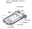
図1−図2を用いて説明する。図1は第1の形態例のシャーシがモックアップの第1の外観ケースに設けられた状態を説明する図、図2は図1のシャーシが第2の外観ケースに設けられた状態を説明する図である。
[First embodiment]
This will be described with reference to FIGS. FIG. 1 is a diagram illustrating a state in which the chassis of the first embodiment is provided in the first appearance case of the mockup, and FIG. 2 is a diagram illustrating a state in which the chassis of FIG. 1 is provided in the second appearance case. FIG.
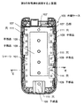
図1に示すように、シャーシ1には、複数の穴3が形成されている。一方、第1の外観ケース5の内壁面には、シャーシ1の穴3を挿通する複数の凸部7が形成されている。そして、シャーシ1の穴3と第1の外観ケース5の凸部7とは、圧入、溶着、接着等の手法で、固定されてる。このような手法で、第1の外観ケース5の凸部7とシャーシ1の穴3とが固定された後は、第1の外観ケース5の凸部7はシャーシ1に形成された凸部として機能する。
As shown in FIG. 1, a plurality of
第1の外観ケース5の表面に配設される3つの第1の子部品9には、シャーシ1を挿通した第1の外観ケース5の凸部7が挿通する穴11が形成されている。そして、各第1の子部品9の穴11と凸部7とは、圧入、溶着、接着等の手法で、固定されてる。
The three
従って、シャーシ1に形成された凸部(第1の外観ケース5の凸部7)は、第1の子部品9のシャーシ1に対する位置決めを行なう子部品位置決め部と、第1の子部品9のシャーシ1に対する固定を行う子部品固定部として機能している。
Therefore, the convex portion (the
次に、図2に示すように、第1の外観ケース5と意匠が異なる第2の外観ケース13にシャーシ1が設けられている。第2の外観ケース13の内壁面には、シャーシ1の穴3を挿通する複数の凸部15が形成されている。そして、シャーシ1の穴3と第2の外観ケース13の凸部15とは、圧入、溶着、接着等の手法で、固定されてる。このような手法で第2の外観ケース13の凸部15とシャーシ1の穴3とが固定された後は、第2の外観ケース13の凸部15はシャーシ1に形成された凸部として機能する。
Next, as shown in FIG. 2, the chassis 1 is provided in a second appearance case 13 having a design different from that of the first appearance case 5. On the inner wall surface of the second appearance case 13, a plurality of
第2の外観ケース13の表面には4つの第2の子部品17が配設される。第2の子部品17のシャーシ1に対する配設位置は、第1の子部品9のシャーシ1に対する配設位置と異なっている。4つの第2の子部品17には、シャーシ1を挿通した第2の外観ケース13の凸部15(第1の子部品9の穴11を挿通する凸部とは異なる凸部)が挿通する穴19が形成されている。そして、各第2の子部品17の穴19と凸部15とは、圧入、溶着、接着等の手法で、固定されてる。
Four second child parts 17 are disposed on the surface of the second appearance case 13. The arrangement position of the second child component 17 with respect to the chassis 1 is different from the arrangement position of the
即ち、シャーシ1に形成された凸部(第2の外観ケース13の凸部15)は、第2の子部品17のシャーシ1に対する位置決めを行なう子部品位置決め部と、第2の子部品17のシャーシ1に対する固定を行う子部品固定部として機能している。
That is, the convex portion formed on the chassis 1 (the
また、21は、凸部15が挿通する穴23が形成がされ、シャーシ1に設けられる内蔵物である。
このような構成によれば、シャーシ1に穴3を複数設けたことにより、子部品のシャーシ1に対する位置決めを行なう子部品位置決め部と、前記子部品の前記シャーシに対する固定を行う子部品固定部とを複数設けるとが可能となり、外観ケースの形状に応じて子部品を取り付けることができる。よって、シャーシ1を0から設計し、製造することなく、再利用できる。このため、開発費用、製造費用が低減でき、設計時間を短縮できる。
[第2の形態例]
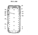
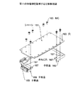
図3−図5を用いて説明する。図3は第2の形態例を説明する分解斜視図、図4は図3の上面図、図5は図4の切断線A−Aでの断面図である。
Reference numeral 21 denotes a built-in object provided in the chassis 1 in which a hole 23 through which the
According to such a configuration, by providing a plurality of
[Second Embodiment]
This will be described with reference to FIGS. 3 is an exploded perspective view for explaining a second embodiment, FIG. 4 is a top view of FIG. 3, and FIG. 5 is a cross-sectional view taken along a cutting line AA of FIG.
シャーシ31には、複数の穴33が形成されている。一方、外観ケース35の内壁面には、シャーシ31の穴33を挿通する複数のボス(凸部)37が形成されている。そして、シャーシ31の穴33と外観ケース35のボス37とは、圧入、溶着、接着等の手法で、固定されてる。このような手法で、外観ケース35のボス37とシャーシ31の穴33とが固定された後は、外観ケース35のボス37はシャーシ31に形成された凸部として機能する。
A plurality of
外観ケース35の表面に配設される5つの子部品39には、シャーシ31を挿通した外観ケース35のボス37が挿通する穴41が形成されている。
従って、シャーシ31に形成された凸部(外観ケース35のボス37)は、子部品39のシャーシ31に対する位置決めを行なう子部品位置決め部として機能している。
Holes 41 through which the
Therefore, the convex portion (the
また、43は、ボス37が挿通する穴45が形成がされ、シャーシ31に設けられる内蔵物である。
このような構成によれば、シャーシ31が金属の場合、シャーシ31に凸部を形成するよりも効率的である。
[第3の形態例]
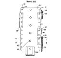
図6−図8を用いて説明する。図6は第3の形態例を説明する分解斜視図、図7は図6の上面図、図8は図7の切断線B−Bでの断面図である。
Reference numeral 43 denotes a built-in object in which a hole 45 through which the
According to such a structure, when the
[Third embodiment]
This will be described with reference to FIGS. 6 is an exploded perspective view for explaining a third embodiment, FIG. 7 is a top view of FIG. 6, and FIG. 8 is a cross-sectional view taken along a cutting line BB of FIG.
シャーシ51には、複数の凸部53が形成されている。図示しない外観ケースの表面に配設される5つの子部品59には、シャーシ51に形成された凸部53が挿通する穴68が形成されている。
A plurality of
従って、シャーシ51に形成された凸部53は、子部品59のシャーシ51に対する位置決めを行なう子部品位置決め部として機能している。
このような構成によれば、子部品59の材質が樹脂で、金型を用いて製造される場合、子部品59に凸部を形成すると、ヒケなどの外観不具合を生じる場合がある。しかし、本形態例では、子部品59に穴61を形成することにより、子部品に外観不具合が生じない。
[第4の形態例]
図9−図11を用いて説明する。図9は第4の形態例を説明する分解斜視図、図10は図9の上面図、図11は図10の切断線C−Cでの断面図である。
Therefore, the
According to such a configuration, when the
[Fourth embodiment]
This will be described with reference to FIGS. 9 is an exploded perspective view for explaining a fourth embodiment, FIG. 10 is a top view of FIG. 9, and FIG. 11 is a cross-sectional view taken along the section line CC of FIG.
シャーシ71には、複数の穴73が形成されている。図示しない外観ケースの表面に配設される5つの子部品79には、シャーシ71に形成された穴73に挿通する凸部81が形成されている。
A plurality of
従って、シャーシ71に形成された穴83は、子部品79のシャーシ71に対する位置決めを行なう子部品位置決め部として機能している。
このような構成によれば、子部品79の材質が樹脂で、金型を用いて製造される場合、子部品79に穴を形成すると、子部品79の強度不足を生じる場合がある。しかし、本形態例では、子部品79に凸部81を形成することにより、子部品79に強度不足が発生しない。
[第5の形態例]
図12−図14を用いて説明する。図12は第5の形態例を説明する分解斜視図、図13は図12の上面図、図14は図13の切断線D−Dでの断面図である。
Accordingly, the
According to such a configuration, when the
[Fifth Embodiment]
This will be described with reference to FIGS. 12 is an exploded perspective view for explaining a fifth embodiment, FIG. 13 is a top view of FIG. 12, and FIG. 14 is a cross-sectional view taken along a cutting line DD of FIG.
シャーシ91上には、シャーシ91上に立設されたリブ(壁)83が複数形成されている。そして、シャーシ91上に、6つの子部品99が取り付けられる。こられの子部品99の一端部は、リブ83に当接するようにシャーシ91上に配置され、両面テープ85を用いてシャーシ91上に取り付けられる。
A plurality of ribs (walls) 83 standing on the chassis 91 are formed on the chassis 91. Then, six
従って、シャーシ91上のリブ83は、子部品99のシャーシ91に対する位置決めを行なう子部品位置決め部として機能している。
このような構成によれば、子部品99をリブ83に突き当てるだけで、子部品99のシャーシ91に対する位置決めが行えるので、部品組み立て時の効率化を図ることができる。
[第6の形態例]
図15−図17を用いて説明する。図15は第6の形態例を説明する上面図、図16は図15の切断線E−Eでの断面図、図17は図16のF部分の拡大図である。
Therefore, the
According to such a configuration, the
[Sixth embodiment]
This will be described with reference to FIGS. FIG. 15 is a top view for explaining the sixth embodiment, FIG. 16 is a sectional view taken along the cutting line EE of FIG. 15, and FIG. 17 is an enlarged view of a portion F of FIG.
外観ケース105内に設けられたシャーシ101には、複数の凸部107が形成されている。
外観ケース105の表面に配設される5つの子部品109には、シャーシ101の凸部107が挿通する穴111が形成されている。
A plurality of
従って、シャーシ101の凸部107は、子部品109のシャーシ101に対する位置決めを行なう子部品位置決め部として機能している。
そして、本形態例では、図17に示すように、子部品109とシャーシ101の凸部(子部品位置決め部)107との隙間(y)が、子部品109と外観ケース105との隙間(x)より大きくなるように設定されている。
Accordingly, the
In this embodiment, as shown in FIG. 17, a gap (y) between the
このような構成によれば、子部品109とシャーシ101の凸部(子部品位置決め部)107との隙間(y)が、子部品109と外観ケース105との隙間(x)より大きくなるように設定したことにより、子部品109と外観ケース105との間のガタツキを取り除いた状態や、子部品109と外観ケース105との間の段差を調整した状態で、子部品109をシャーシ101に固定することができる。
[第7の形態例]
図18−図19を用いて説明する。図18は第7の形態例を説明する斜視図、図19は図15の切断線G−Gでの断面図である。
According to such a configuration, the gap (y) between the
[Seventh Embodiment]
This will be described with reference to FIGS. 18 is a perspective view for explaining a seventh embodiment, and FIG. 19 is a cross-sectional view taken along a cutting line GG in FIG.
図において、シャーシ121には、複数の穴123が形成されている。外観ケース125の表面に配設される子部品129には、シャーシ121の穴123を挿通可能な凸部127が形成されている。
In the figure, a plurality of
本形態例では、子部品129の凸部127の径が、シャーシ121の穴123の径より大きく設定され、凸部127が穴123に圧入されるようになっている。従って、シャーシ121上の穴123は、子部品129のシャーシ121に対する固定を行う子部品固定部として機能する。
In this embodiment, the diameter of the convex portion 127 of the child component 129 is set larger than the diameter of the
このような構成によれば、子部品129は、圧入によりシャーシ121に固定されるので、子部品129のシャーシ121に対するガタツキを防止できる。
[第8の形態例]
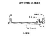
図20−図21を用いて説明する。図20は第8の形態例を説明する斜視図、図21は図20の切断線H−Hでの断面図である。
According to such a configuration, since the child component 129 is fixed to the chassis 121 by press-fitting, the child component 129 can be prevented from rattling with respect to the chassis 121.
[Eighth embodiment]
This will be described with reference to FIGS. FIG. 20 is a perspective view for explaining an eighth embodiment, and FIG. 21 is a sectional view taken along the cutting line H-H in FIG.
図において、シャーシ131には、複数の凸部133が形成されている。外観ケース135の表面に配設される子部品139には、シャーシ131の凸部133が挿通可能な穴137が形成されている。 In the figure, a plurality of convex portions 133 are formed on the chassis 131. A hole 137 into which the convex portion 133 of the chassis 131 can be inserted is formed in the child component 139 disposed on the surface of the appearance case 135.
本形態例では、シャーシ131の凸部133の径が、子部品139の穴137の径より大きく設定され、凸部133が穴137に圧入されるようになっている。従って、シャーシ131上の凸部133は、子部品139のシャーシ131に対する固定を行う子部品固定部として機能する。 In this embodiment, the diameter of the convex portion 133 of the chassis 131 is set larger than the diameter of the hole 137 of the child component 139 so that the convex portion 133 is press-fitted into the hole 137. Accordingly, the convex portion 133 on the chassis 131 functions as a child component fixing portion that fixes the child component 139 to the chassis 131.
このような構成によれば、子部品139は、圧入によりシャーシ131に固定されるので、子部品139のシャーシ131に対するガタツキを防止できる。
[第9の形態例]
図22を用いて説明する。図22は第9の形態例を説明する分解斜視図である。
According to such a configuration, since the child component 139 is fixed to the chassis 131 by press-fitting, the child component 139 can be prevented from rattling with respect to the chassis 131.
[Ninth Embodiment]
This will be described with reference to FIG. FIG. 22 is an exploded perspective view for explaining a ninth embodiment.
図において、シャーシ141には、複数の穴143が形成されている。外観ケース145の表面に配設される子部品149には、シャーシ141の穴143に挿通可能な凸部147が形成されている。
In the drawing, a plurality of holes 143 are formed in the chassis 141. A
本形態例では、子部品149の凸部147がシャーシ141の穴143に嵌合し、両者は接着されるようになっている。従って、シャーシ141の穴143は、子部品149のシャーシ141に対する固定を行う子部品固定部として機能する。
In this embodiment, the
このような構成によれば、子部品149の凸部147が、シャーシ141の穴143に接着されることにより、ガタツキを防止できる。
なお、接着としては、溶着、溶接、接着材等があるが、限定するものではない。
[第10の形態例]
図23を用いて説明する。図23は第10の形態例を説明する分解斜視図である。
According to such a configuration, the
In addition, although there exist welding, welding, an adhesive material etc. as adhesion | attachment, it is not limited.
[Tenth Embodiment]
This will be described with reference to FIG. FIG. 23 is an exploded perspective view for explaining the tenth embodiment.
図において、シャーシ151には、複数の凸部153が形成されている。外観ケース155の表面に配設される子部品159には、シャーシ151の凸部153が挿通可能な穴157が形成されている。 In the figure, the chassis 151 is formed with a plurality of convex portions 153. A hole 157 into which the convex portion 153 of the chassis 151 can be inserted is formed in the child component 159 disposed on the surface of the external case 155.
本形態例では、子部品159の穴157にシャーシ151の凸部153が嵌合し、両者は接着されるようになっている。従って、シャーシ151の凸部153は、子部品159のシャーシ151に対する固定を行う子部品固定部として機能する。 In this embodiment, the convex portion 153 of the chassis 151 is fitted into the hole 157 of the child component 159, and both are bonded. Therefore, the convex portion 153 of the chassis 151 functions as a child component fixing portion that fixes the child component 159 to the chassis 151.
このような構成によれば、子部品159の穴157にシャーシ151の凸部153が接着されることにより、ガタツキを防止できる。
又、外観ケース155の内壁面に凸部を形成すると、ヒケなどの外観不具合を生じる場合がある。しかし、本形態例では、外観ケース155に凸部を形成しなくてもよいので、外観ケース155の外観不良が生じない。
According to such a configuration, the projection 153 of the chassis 151 is adhered to the hole 157 of the child component 159, thereby preventing rattling.
In addition, when a convex portion is formed on the inner wall surface of the appearance case 155, appearance defects such as sink marks may occur. However, in this embodiment, no convex portion is formed on the appearance case 155, so that the appearance case 155 does not have an appearance defect.
なお、接着としては、溶着、溶接、接着材等があるが、限定するものではない。
[第11の形態例]
図24−図26を用いて説明する。図24は第11の形態例を説明する分解斜視図、図25は図24の上面図、図26は図25の切断線I−Iでの断面図である。
In addition, although there exist welding, welding, an adhesive material etc. as adhesion | attachment, it is not limited.
[Eleventh embodiment]
This will be described with reference to FIGS. 24 is an exploded perspective view for explaining an eleventh embodiment, FIG. 25 is a top view of FIG. 24, and FIG. 26 is a cross-sectional view taken along a cutting line II in FIG.
図において、シャーシ161には、複数の穴163が形成されている。外観ケースの表面に配設される子部品169には、ねじ165が螺合可能なめねじ穴167が形成されている。
In the drawing, a plurality of
シャーシ161の穴163は、ねじ165の首部165aが挿通し、さらに、このねじ165の頭部165bはシャーシ161の穴163の開口部近傍に押接するように設定されている。
The
従って、シャーシ161の穴163は、子部品169のシャーシ161に対する固定を行う子部品固定部として機能する。
このような構成によれば、シャーシ161の穴163は、ねじ165の首部165aが挿通し、さらに、このねじ165の頭部165bはシャーシ161の穴163の開口部近傍に押接すればよく、穴163の寸法、及び位置を厳しく管理する必要がない。よって、穴163の形成のコストが低減できる。又、ねじ165を用いることにより、何度も子部品169の取り付け、取り外しができる。
[第12の形態例]
図27−図29を用いて説明する。図27は第12の形態例を説明する分解斜視図、図28は図27の上面図、図29は図28の切断線J−Jでの断面図である。
Therefore, the
According to such a configuration, the
[Twelfth embodiment]
This will be described with reference to FIGS. 27 is an exploded perspective view for explaining the twelfth embodiment, FIG. 28 is a top view of FIG. 27, and FIG. 29 is a cross-sectional view taken along the section line JJ of FIG.
図において、シャーシ171には、ねじ175が螺合可能な複数のめねじ穴173が形成されている。外観ケースの表面に配設される子部品179には、穴177が形成されている。
In the figure, the
子部品179の穴1177は、ねじ175の首部175aが挿通し、さらに、このねじ175の頭部175bは子部品179の穴173の開口部近傍に押接するように設定されている。
The hole 1177 of the
従って、シャーシ171のめねじ穴173は、子部品179のシャーシ171に対する固定を行う子部品固定部として機能する。
このような構成によれば、子部品179の穴177は、ねじ175の首部175aが挿通し、さらに、このねじ175の頭部175bは子部品179の穴177の開口部近傍に押接すればよく、穴177の寸法、及び位置を厳しく管理する必要がない。よって、穴177の形成のコストが低減できる。又、ねじ175を用いることにより、何度も子部品179の取り付け、取り外しができる。
[第13の形態例]
図30を用いて説明する。図30は第13の形態例を説明する分解斜視図である。
Accordingly, the
According to such a configuration, the hole 177 of the
[Thirteenth embodiment]
This will be described with reference to FIG. FIG. 30 is an exploded perspective view illustrating a thirteenth embodiment.
第1の外観ケース183には穴184が、第2の外観ケース185には、めねじ穴186が形成されている。第1の外観ケース183、第2の外観ケース185の間には、子部品187、シャーシ181が設けられる。そして、シャーシ181には穴182が形成され、子部品187には、穴188が設けられている。
A
シャーシ181の穴182には、頭部189aが第1の外観ケースに183形成された穴184の開口近傍に押接し、首部189bが第1の外観ケース183の穴184、子部品187に形成された穴188を挿通し、第2の外観ケース185のめねじ穴186に螺合するねじ189の首部189bが挿通するようになっている。
In the hole 182 of the chassis 181, the head 189 a is pressed against the vicinity of the opening of the
従って、シャーシ181の穴182は、子部品187のシャーシ181に対する固定を行う子部品固定部として機能する。
このような構成によれば、第1の外観ケース183、子部品187、シャーシ181、第2の外観ケース185の位置合わせをした後、一つのねじ189で、第1の外観ケース183、子部品187、シャーシ181、第2の外観ケース185を組み付けることができる。
[第14の形態例]
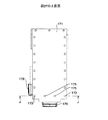
図31−図33を用いて説明する。図31は第14の形態例を説明する斜視図、図32は図31の上面図、図33は図31の切断線K−Kでの断面図である。
Therefore, the hole 182 of the chassis 181 functions as a child component fixing portion that fixes the child component 187 to the chassis 181.
According to such a configuration, after the first appearance case 183, the child part 187, the chassis 181, and the second appearance case 185 are aligned, the first appearance case 183 and the child parts are aligned with one
[Fourteenth embodiment]
This will be described with reference to FIGS. 31 is a perspective view for explaining a fourteenth embodiment, FIG. 32 is a top view of FIG. 31, and FIG. 33 is a cross-sectional view taken along the cutting line KK of FIG.
シャーシ191には、スナップフィット193が形成されている。このスナップフィット193は、外観ケースの表面に配置される子部品195の被係合部に係脱可能となっている。
A
従って、シャーシ191のスナップフィット193は、子部品195のシャーシ191に対する固定を行う子部品固定部として機能する。
このような構成によれば、以下のような効果を得ることができる。
(1)スナップフィット193は、部品点数が少なく単純な構造をしており、安価である。
(2)様々な材料の組み合わせにも対応可能である。
(3)同時に複数箇所の結合が可能である。結合のための工程数が少なく、組立工程数を減らすことが可能である。
(4)特殊な組立工具を必要とせず、組立てる際、大きな柔軟性を持っている。サービス、修理、リサイクルするために容易に分
解しやすい機構にできる。
[第15の形態例]
図34−図36を用いて説明する。図34は第15の形態例を説明する斜視図、図35は図34の上面図、図36は図35の切断線L−Lでの断面図である。
Therefore, the snap fit 193 of the
According to such a configuration, the following effects can be obtained.
(1) The snap fit 193 has a simple structure with a small number of parts and is inexpensive.
(2) It is possible to deal with various combinations of materials.
(3) Multiple locations can be combined at the same time. The number of processes for coupling is small, and the number of assembly processes can be reduced.
(4) No special assembly tool is required, and there is great flexibility when assembling. Can be easily disassembled for service, repair and recycling.
[15th embodiment]
This will be described with reference to FIGS. 34 is a perspective view for explaining the fifteenth embodiment, FIG. 35 is a top view of FIG. 34, and FIG. 36 is a sectional view taken along the cutting line LL of FIG.
シャーシ201には、外観ケースの表面に配置される子部品205が当接可能な立壁部203が形成されている。この立壁部203には、両面テープ207を用いて子部品205が取り付けられている。即ち、両面テープ207は、子部品205に接着可能な接着層となっている。
The
従って、シャーシ201の接着層(両面テープ207)は、子部品205のシャーシ201に対する固定を行う子部品固定部として機能する。
このような構成によれば、組付が簡単となる。
[第16の形態例]
図37−図39を用いて説明する。図37は第16の形態例を説明する斜視図、図38は図37の上面図、図39は図38の切断線M−Mでの断面図である。
Therefore, the adhesive layer (double-sided tape 207) of the
According to such a configuration, assembly is simplified.
[Sixteenth embodiment]
This will be described with reference to FIGS. 37 is a perspective view for explaining the sixteenth embodiment, FIG. 38 is a top view of FIG. 37, and FIG. 39 is a cross-sectional view taken along the cutting line MM of FIG.
シャーシ211上には、弾性体213が設けられている。一方、外観ケースの表面に配置される子部品215には、針217が設けられている。そして、子部品215の針217が弾性体213に刺さって、子部品215が保持されるようなっている。
An
従って、シャーシ211の弾性体213は、子部品215のシャーシ211に対する固定を行う子部品固定部として機能する。
このような構成によれば、組付が簡単となる。又、子部品215の配置位置が自由に決められる。
[第17の形態例]
図40−図41を用いて説明する。図40は第17の形態例を説明する斜視図、図41は図40の上面図である。
Therefore, the
According to such a configuration, assembly is simplified. Further, the arrangement position of the
[Seventeenth embodiment]
This will be described with reference to FIGS. FIG. 40 is a perspective view for explaining a seventeenth embodiment, and FIG. 41 is a top view of FIG.
シャーシ211上には、複数の凸部213が形成されている。
外観ケースの表面に配置される子部品215、215’には、それぞれ凸部213が嵌合可能な複数の穴217、217’が設けられている。本形態例では、子部品215の穴217の間隔(8mm:図41参照)と、子部品215’の穴217’の間隔(4mm:図41参照)とは異なるように設定されている。
A plurality of
A plurality of
一方、シャーシ211の子部品215、215’に対する凸部213の間隔が、固定される子部品215、215’に応じてそれぞれ異なっている。
従って、シャーシ211の凸部213は、子部品215、215’のシャーシ211に対する固定を行う子部品固定部として機能する。
On the other hand, the intervals of the
Therefore, the
このような構成によれば、誤った位置に子部品215、215’を組み付けることがなくなる。
[第18の形態例]
図42−図43を用いて説明する。図42は第18の形態例を説明する斜視図、図43は図42の上面図である。
According to such a configuration, the
[Eighteenth embodiment]
This will be described with reference to FIGS. 42 is a perspective view for explaining an eighteenth embodiment, and FIG. 43 is a top view of FIG.
シャーシ221上には、複数の凸部223が形成されている。
外観ケースの表面に配置される子部品225、225’には、それぞれ凸部223が嵌合可能な複数の穴227、227’が設けられている。本形態例では、子部品225の穴227の形状(丸、四角、三角)と、子部品225’の穴227’の形状(四角、丸)とは異なるように設定されている。
A plurality of
A plurality of holes 227 and 227 ′ into which the
一方、シャーシ221の子部品225、225’に対する凸部223の形状が、固定される子部品215、215’に応じてそれぞれ異なっている。
従って、シャーシ221の凸部223は、子部品225、225’のシャーシ221に対する固定を行う子部品固定部として機能する。
On the other hand, the shape of the
Therefore, the
このような構成によれば、誤った位置に子部品225、225’を組み付けることがなくなる。
[第19形態例]
図44を用いて説明する。図44は第19の形態例を説明する斜視図である。
According to such a configuration, the
[Nineteenth embodiment]
This will be described with reference to FIG. FIG. 44 is a perspective view for explaining a nineteenth embodiment.
シャーシ231上には、複数の凸部233が形成されている。
外観ケースの表面に配置される子部品235、235’、235’’、235’’’には、それぞれ凸部233が嵌合可能な穴237が設けられている。 従って、シャーシ231の凸部233は、子部品235、235’、235’’、235’’’のシャーシ231に対する固定を行う子部品固定部として機能する。
A plurality of convex portions 233 are formed on the chassis 231.
The child parts 235, 235 ′, 235 ″, 235 ′ ″ arranged on the surface of the outer case are provided with holes 237 into which the convex portions 233 can be fitted respectively. Therefore, the convex portion 233 of the chassis 231 functions as a child component fixing portion that fixes the child components 235, 235 ′, 235 ″, and 235 ′ ″ to the chassis 231.
そして、本形態例では、子部品235、235’、235’’、235’’’の色がそれぞれ異なっている。又、シャーシ221の子部品235、235’、235’’、235’’’に対する凸部233の色も、固定される子部品235、235’、235’’、235’’’の色と同じ色となっている。
In this embodiment, the colors of the child parts 235, 235 ', 235 ", 235" "are different from each other. Also, the color of the convex portion 233 for the child parts 235, 235 ′, 235 ″, 235 ′ ″ of the
このような構成によれば、誤った位置に子部品235、235’、235’’、235’’’を組み付けることがなくなる。
(付記1)
モックアップの外観ケース内に設けられ、前記外観ケースの表面に配設される子部品が取り付けられるシャーシであって、
前記子部品の前記シャーシに対する位置決めを行なう子部品位置決め部と、
前記子部品の前記シャーシに対する固定を行う子部品固定部と、
が複数設けられたことを特徴とするシャーシ。
(付記2)
前記子部品位置決め部は、
前記シャーシに設けられた穴であり、
該穴は、前記外観ケースに設けられ、前記子部品に設けられた穴を挿通する凸部が嵌合する穴であることを特徴とする付記1に記載のシャーシ。
(付記3)
前記子部品位置決め部は、
前記シャーシに設けられ、前記子部品に設けられた穴に嵌合する凸部、
前記シャーシに設けられ、前記子部品に設けられた凸部が嵌合する穴のうちの少なくともちらか一方であることを特徴とする付記1記載のシャーシ。
(付記4)
前記位置決め部は、
前記シャーシに設けられ、前記子部品が当接するリブであることを特徴とする付記1記載のシャーシ。
(付記5)
前記子部品と前記シャーシの子部品固定部との隙間を、前記子部品と前記外観ケースとの隙間より大きくなるように設定されたことを特徴とする付記1乃至3のいずれかに記載のシャーシ。
(付記6)
前記子部品固定部は、
前記凸部の径が、前記穴の径より大きく設定され、
前記凸部が前記穴に圧入されることでなされることを特徴とする付記2又は3記載のシャーシ。
(付記7)
前記子部品固定部は、
前記凸部が前記穴に嵌合し、両者が接着されることでなされることを特徴とする付記2又は3記載のシャーシ。
(付記8)
前記子部品固定部は、
前記シャーシに設けられた穴であり、
該穴は、前記子部品に形成されためねじ穴に螺合するねじの首部が挿通し、前記ねじの頭部が前記穴の開口部近傍に押接することを特徴とする付記1記載のシャーシ。
(付記9)
前記子部品固定部は、
前記シャーシに設けられためねじ穴であり、
該めねじ穴は、頭部が前記子部品に形成された穴の開口近傍に押接し、首部が前記子部品の穴を挿通したねじが螺合することを特徴とする付記1記載のシャーシ。
(付記10)
前記外観ケースは、第1の外観ケース、第2の外観ケースからなり、
前記第1の外観ケース、前記第2の外観ケースの間に、前記子部品、前記シャーシが設けられ、
前記子部品固定部は、
前記シャーシに設けられた穴であり、
該穴は、頭部が前記第1の外観ケースに形成された穴の開口近傍に押接し、首部が前記第1の外観ケースの穴、前記子部品に形成された穴を挿通し、前記第2の外観ケースのめねじ穴に螺合するねじの首部が挿通することを特徴とする付記1記載のシャーシ。
(付記11)
前記子部品固定構造は、
前記シャーシに設けられ、前記子部品の被係合部に係脱可能なスナップフィットであることを特徴とする付記1記載のシャーシ。
(付記12)
前記子部品固定構造は、
前記シャーシに設けられ、前記子部品に接着可能な接着層であることを特徴とする付記1記載のシャーシ。
(付記13)
前記子部品固定構造は、
前記シャーシに設けられ、前記子部品に設けられた針が刺さって、前記子部品が保持される弾性体であることを特徴とする付記1記載のシャーシ。
(付記14)
前記シャーシに対して、複数種類の子部品が設けられ、
各子部品に対して、複数の前記子部品固定部が前記シャーシに設けられ、
前記各子部品に対する前記子部品固定部の間隔が、固定される前記子部品に応じてそれぞれ異なることを特徴とする付記6又は7記載のシャーシ。
(付記15)
前記シャーシに対して、複数種類の子部品が設けられ、
前記子部品位置決め部の断面形状が、位置決めされる前記子部品に応じてそれぞれ異なることを特徴とする付記2又は3記載のシャーシ。
(付記16)
前記シャーシに対して、複数種類の子部品が設けられ、
前記子部品位置決め部の色が、位置決めされる子部品の色と同じであることを特徴とする付記2、3、15のいずれかに記載のシャーシ。
According to such a configuration, the child parts 235, 235 ′, 235 ″, and 235 ′ ″ are not assembled at wrong positions.
(Appendix 1)
A chassis provided in a mock-up external case, to which a child component disposed on the surface of the external case is attached,
A child component positioning unit for positioning the child component with respect to the chassis;
A child component fixing portion for fixing the child component to the chassis;
A chassis characterized in that a plurality of are provided.
(Appendix 2)
The child component positioning part is
A hole provided in the chassis;
2. The chassis according to claim 1, wherein the hole is provided in the external case and is a hole into which a convex portion that passes through the hole provided in the child component is fitted.
(Appendix 3)
The child component positioning part is
Protrusions provided in the chassis and fitted into holes provided in the child parts,
The chassis according to appendix 1, wherein the chassis is provided with at least one of holes into which convex portions provided on the child parts are fitted.
(Appendix 4)
The positioning part is
The chassis according to appendix 1, wherein the chassis is a rib provided on the chassis and against which the child component abuts.
(Appendix 5)
The chassis according to any one of appendices 1 to 3, wherein a gap between the child component and the child component fixing portion of the chassis is set to be larger than a gap between the child component and the outer case. .
(Appendix 6)
The child component fixing part is
The diameter of the convex portion is set larger than the diameter of the hole,
The chassis according to
(Appendix 7)
The child component fixing part is
The chassis according to
(Appendix 8)
The child component fixing part is
A hole provided in the chassis;
2. The chassis according to claim 1, wherein the hole is formed in the child component, so that a neck portion of a screw that is screwed into the screw hole is inserted, and a head portion of the screw is pressed in the vicinity of the opening of the hole.
(Appendix 9)
The child component fixing part is
It is a screw hole for being provided in the chassis,
The chassis according to claim 1, wherein the female screw hole has a head pressed near an opening of a hole formed in the child component, and a screw having a neck portion inserted through the hole of the child component is screwed.
(Appendix 10)
The external case includes a first external case and a second external case,
Between the first appearance case and the second appearance case, the child component and the chassis are provided,
The child component fixing part is
A hole provided in the chassis;
The hole has a head pressed into the vicinity of the opening of the hole formed in the first appearance case, and a neck portion is inserted through the hole of the first appearance case and the hole formed in the child part. 2. The chassis according to appendix 1, wherein a neck portion of a screw that is screwed into a female screw hole of the outer appearance case 2 is inserted.
(Appendix 11)
The child component fixing structure is
The chassis according to claim 1, wherein the chassis is a snap fit that is provided on the chassis and is detachable from and engaged with an engaged portion of the child component.
(Appendix 12)
The child component fixing structure is
The chassis according to claim 1, wherein the chassis is an adhesive layer that is provided on the chassis and can be bonded to the child component.
(Appendix 13)
The child component fixing structure is
The chassis according to claim 1, wherein the chassis is an elastic body that is provided on the chassis and is held by the needle provided on the child component to hold the child component.
(Appendix 14)
Multiple types of child parts are provided for the chassis,
For each child component, a plurality of child component fixing portions are provided in the chassis,
The chassis according to
(Appendix 15)
Multiple types of child parts are provided for the chassis,
The chassis according to
(Appendix 16)
Multiple types of child parts are provided for the chassis,
The chassis according to any one of
1 シャーシ
9 子部品
1
Claims (5)
整列して設けられた複数の穴と、
前穴に前記子部品を固定する子部品固定部と、
を有することを特徴とするシャーシ。 A chassis provided in a mock-up external case, to which a child component disposed on the surface of the external case is attached,
A plurality of aligned holes,
A child component fixing portion for fixing the child component to the front hole;
Chassis and having a.
前記シャーシに設けられ、前記子部品に設けられた穴に嵌合する凸部と、
前凸部に前記子部品の固定する子部品固定部と、
を有することを特徴とするシャーシ。 A chassis provided in a mock-up external case, to which a child component disposed on the surface of the external case is attached,
Protrusions that are provided in the chassis and fit into holes provided in the child parts,
A child component fixing portion for fixing the child component to the front convex portion;
Features and to Resid Yashi to have a.
前記凸部の径が、前記電子部品に設けられた穴の径より大きく設定され、
前記凸部が前記穴に圧入されることでなされることを特徴とする請求項3記載のシャーシ。 The child component fixing part is
The diameter of the convex portion is set larger than the diameter of the hole provided in the electronic component,
The chassis according to claim 3, wherein the protrusion is made by being press-fitted into the hole .
Priority Applications (1)
| Application Number | Priority Date | Filing Date | Title |
|---|---|---|---|
| JP2006185536A JP4608465B2 (en) | 2006-07-05 | 2006-07-05 | Chassis |
Applications Claiming Priority (1)
| Application Number | Priority Date | Filing Date | Title |
|---|---|---|---|
| JP2006185536A JP4608465B2 (en) | 2006-07-05 | 2006-07-05 | Chassis |
Publications (3)
| Publication Number | Publication Date |
|---|---|
| JP2008017112A JP2008017112A (en) | 2008-01-24 |
| JP2008017112A5 JP2008017112A5 (en) | 2009-07-02 |
| JP4608465B2 true JP4608465B2 (en) | 2011-01-12 |
Family
ID=39073734
Family Applications (1)
| Application Number | Title | Priority Date | Filing Date |
|---|---|---|---|
| JP2006185536A Expired - Fee Related JP4608465B2 (en) | 2006-07-05 | 2006-07-05 | Chassis |
Country Status (1)
| Country | Link |
|---|---|
| JP (1) | JP4608465B2 (en) |
Families Citing this family (1)
| Publication number | Priority date | Publication date | Assignee | Title |
|---|---|---|---|---|
| JP4776722B2 (en) | 2009-12-25 | 2011-09-21 | 株式会社東芝 | Electronics |
Citations (2)
| Publication number | Priority date | Publication date | Assignee | Title |
|---|---|---|---|---|
| JPH11317794A (en) * | 1997-11-28 | 1999-11-16 | Nokia Mobile Phones Ltd | Housing assembly for radio telephone set |
| JP2000148024A (en) * | 1998-11-11 | 2000-05-26 | Toppan Printing Co Ltd | Model sample of portable phone set |
-
2006
- 2006-07-05 JP JP2006185536A patent/JP4608465B2/en not_active Expired - Fee Related
Patent Citations (2)
| Publication number | Priority date | Publication date | Assignee | Title |
|---|---|---|---|---|
| JPH11317794A (en) * | 1997-11-28 | 1999-11-16 | Nokia Mobile Phones Ltd | Housing assembly for radio telephone set |
| JP2000148024A (en) * | 1998-11-11 | 2000-05-26 | Toppan Printing Co Ltd | Model sample of portable phone set |
Also Published As
| Publication number | Publication date |
|---|---|
| JP2008017112A (en) | 2008-01-24 |
Similar Documents
| Publication | Publication Date | Title |
|---|---|---|
| JP5978032B2 (en) | Housing and manufacturing method thereof | |
| JP4608465B2 (en) | Chassis | |
| KR101469095B1 (en) | Electronic Device Intenna Manufacturing Method using 3D Printer | |
| JP4834322B2 (en) | Meter device | |
| CN204272519U (en) | Middle board component, frame housing, substrate housings and electronic equipment | |
| JP2014087455A (en) | Band | |
| JP4719557B2 (en) | Small electronic equipment | |
| CN106535527A (en) | In-mold steel disc front casing assembly and terminal equipment | |
| JP2009063486A (en) | Positioning device of bezel member | |
| KR20140078795A (en) | Motor | |
| JP4275675B2 (en) | Micro speaker assembly method and micro speaker | |
| TWI448230B (en) | Housing | |
| CN201146134Y (en) | Error-installation-proof button-pulling orientation structure | |
| JP2001318365A (en) | Liquid crystal panel holding structure | |
| JP2009302080A (en) | Apparatus cabinet | |
| JP4380479B2 (en) | Parts assembly | |
| KR20050115409A (en) | Case joining structure for a communication mobile terminal using a magnetic joining member | |
| US20080102905A1 (en) | Hand-held electronic apparatus | |
| KR100371382B1 (en) | Film inserted image display device housing assembly | |
| JP2008107416A (en) | Optical component and method for manufacturing the same | |
| KR100528775B1 (en) | Navy-key for mobile communication terminal | |
| JP5949514B2 (en) | Assembly member | |
| KR200432691Y1 (en) | Index knob using in action equipment of vehicle seat | |
| JP2012166457A (en) | Method of molding cushion for assembled item | |
| JP3741711B1 (en) | Vertical angle bonding method, vertical angle bonding component, and method of manufacturing vertical angle bonding component |
Legal Events
| Date | Code | Title | Description |
|---|---|---|---|
| A521 | Written amendment |
Free format text: JAPANESE INTERMEDIATE CODE: A523 Effective date: 20090518 |
|
| A621 | Written request for application examination |
Free format text: JAPANESE INTERMEDIATE CODE: A621 Effective date: 20090518 |
|
| A977 | Report on retrieval |
Free format text: JAPANESE INTERMEDIATE CODE: A971007 Effective date: 20100831 |
|
| TRDD | Decision of grant or rejection written | ||
| A01 | Written decision to grant a patent or to grant a registration (utility model) |
Free format text: JAPANESE INTERMEDIATE CODE: A01 Effective date: 20101005 |
|
| A01 | Written decision to grant a patent or to grant a registration (utility model) |
Free format text: JAPANESE INTERMEDIATE CODE: A01 |
|
| A61 | First payment of annual fees (during grant procedure) |
Free format text: JAPANESE INTERMEDIATE CODE: A61 Effective date: 20101008 |
|
| R150 | Certificate of patent or registration of utility model |
Free format text: JAPANESE INTERMEDIATE CODE: R150 |
|
| FPAY | Renewal fee payment (event date is renewal date of database) |
Free format text: PAYMENT UNTIL: 20131015 Year of fee payment: 3 |
|
| LAPS | Cancellation because of no payment of annual fees |