JP4608189B2 - Variant can manufacturing method and expandable mold - Google Patents
Variant can manufacturing method and expandable mold Download PDFInfo
- Publication number
- JP4608189B2 JP4608189B2 JP2003091664A JP2003091664A JP4608189B2 JP 4608189 B2 JP4608189 B2 JP 4608189B2 JP 2003091664 A JP2003091664 A JP 2003091664A JP 2003091664 A JP2003091664 A JP 2003091664A JP 4608189 B2 JP4608189 B2 JP 4608189B2
- Authority
- JP
- Japan
- Prior art keywords
- tag
- diameter
- expanding
- convex
- pattern
- Prior art date
- Legal status (The legal status is an assumption and is not a legal conclusion. Google has not performed a legal analysis and makes no representation as to the accuracy of the status listed.)
- Expired - Fee Related
Links
Images


Description
【0001】
【発明の属する技術分野】
本発明は異形缶製造方法、及びエキスパンド型、特に缶の装飾効果の向上と成形の際の変形歪みの発生の低減を同時に図ることのできる技術に関する。
【0002】
【従来の技術】
例えば飲料缶においては、スリーピース缶と、深絞り缶や絞りしごき缶等のツーピース缶が一般に製造されている。
これらの缶は、ほぼ同一の形状であるため、大量にしかも安価に生産することができる。しかしながら、これらの缶は形状に個性がないので、商品自体を形状により容易に区別することができなかった。
このため、商品の個別化や差別化を目的として、個性的な形状をもち、しかも安価な缶の開発が望まれている。
【0003】
このような要望に応えるため、例えば缶胴上部及び缶胴下部よりも大径の缶胴拡径部を持つ異形缶が考えられる(例えば特許文献1、特許文献2参照)。
例えば円筒状の缶部材内に同一形状の凹凸を持つ金型を配置し、金型により缶部材をエキスパンド成形することにより、缶胴拡径部が形成されている。
【0004】
【特許文献1】
特開昭49−28492号公報
【特許文献2】
特開昭59−163041号公報
【0005】
【発明が解決しようとする課題】
しかしながら、前記異形缶にあっても、缶胴に形成される模様は円周方向の形状が同一で定形化したものであり、さらにバリエーションを増やすことが求められていた。
本発明者らが缶の装飾効果の向上について検討したところ、缶胴に傾斜凹凸模様を成形することが、コスト対装飾効果のバランスに優れていることが分かった。
しかしながら、円筒状缶部材の缶胴になる部分に傾斜凹凸模様を成形しようとすると、該缶胴両端部になる部分に歪みが生じるので、該缶胴の開口端部に成形されるフランジの長さにバラツキが生じる。特に溶接缶は、溶接継目により缶胴の開口端部は真円に形成され難いので、缶胴の両端部での歪みが発生しやすい。
【0006】
このようなフランジの長さのバラツキは、たとえ0.3mm程度であっても、巻締密封不良を起こし易くなってしまうので、円筒状缶部材の缶胴になる部分に傾斜凹凸模様を持つ異形缶を作る際に、缶胴の両端部での歪みの発生を低減することは非常に重要であった。
しかしながら、従来はこのような缶胴の両端部での歪みの発生を低減することのできる適切な技術が存在しないため、缶胴への傾斜凹凸模様の成形は実用化されていないのが実情である。
【0007】
またこのような異形缶であっても、さらに既存の円筒缶用の設備を変更することなく、また自動販売機に既存の円筒缶と同様に入れられることも重要であり、異形缶には、このような既存の設備に対する適応性の確保が重要であった。
本発明は前記従来技術の課題に鑑みなされたものであり、その第一の目的は、缶の装飾効果の向上と、成形の際に発生し易い変形歪みの発生の低減を同時に図ることのできる異形缶製造方法、及びエキスパンド型を提供することにある。
【0008】
【課題を解決するための手段】
本発明者らが前記課題について鋭意検討を行った結果、まず缶胴の開口端部での歪みの発生メカニズムがわかった。すなわち、一般的な定形の凹凸模様を形成する場合に比較し、装飾効果に優れた傾斜凹凸模様を形成する場合は、特に缶胴の変形歪みが生じ易く、しかもその変形歪みは缶胴の開口端部に伝播しやすいのである。
【0009】
さらに、本発明者らが、このような缶胴の変形歪みの発生をできるだけ低減することのできる傾斜凹凸模様の成形技術について検討したところ、缶胴拡径部の上端及び下端の全周に渡って、それぞれ凸部を成形し、これらの凸部間に傾斜凹模様を成形し、傾斜凹模様よりも前記凸部を半径方向外側に張出させることにより、傾斜凹凸模様の成形の際に、缶胴の変形歪みの発生そのものを大幅に低減することできることがわかった。さらに缶胴の変形歪みが生じても、拡径部両端部の凸部により、缶胴開口端部への伝播が遮断されることも見出し、本発明を完成するに至った。
【0010】
すなわち、前記第一の目的を達成するために本発明にかかる異形缶製造方法は、エキスパンド成形工程を含む異形缶製造方法において、
前記エキスパンド成形工程は、拡径しない缶胴上端部及び缶胴下端部に対応する上部逃がし部及び下部逃がし部と、前記缶部材の缶胴上部になる部分から缶胴下部になる部分にかけて内側から半径方向外側に押圧し、所定の寸法を持つ缶胴拡径部となるまで前記缶部材の缶胴になる部分を拡径するための拡径対応部とを外周壁に備え、前記拡径対応部は、前記拡径対応部の上部に相当し、該拡径対応部の上部の全周にわたって設けられた上部タガ対応部と、前記拡径対応部の下部に相当し、該拡径対応部の上部の全周にわたって設けられた下部タガ対応部と、前記外周壁の上部タガ対応部から前記下部タガ対応部にかけて、該外周壁の円周方向に対し斜め方向へと形成された少なくとも凹部を含む傾斜凹凸模様対応部とを備え、前記傾斜凹凸模様対応部は螺旋状であり、その螺旋巻数が正の整数倍であり、且つ前記傾斜凹凸模様対応部の凹部の上端を前記上部タガ対応部よりも下方、且つ半径方向内側に位置させ、該凹部の下端を前記下部タガ対応部よりも上方、且つ半径方向内側に位置させ、前記傾斜凹凸模様対応部の凹部が、前記上部タガ対応部及び下部タガ対応部によって、前記上部逃がし部及び下部逃がし部と隔絶しているエキスパンド型を用いて該円筒状缶部材の缶胴になる部分をエキスパンド成形することを特徴とする。
【0011】
ここで、前記エキスパンド成形は、円筒状缶部材の缶胴拡径部になる部分をその内側から半径方向外側にエキスパンド成形することにより、缶胴上端部及び缶胴下端部よりも大径の缶胴拡径部とする。
また前記第一の目的を達成するために本発明にかかるエキスパンド型は、円筒状缶部材内に配置され、該缶部材の缶胴拡径部になる部分をその内側から半径方向外側にエキスパンド成形することにより、缶胴上端部及び缶胴下端部よりも大径の缶胴拡径部とするための外周壁を持つエキスパンド型において、
前記外周壁は、上部逃がし部及び下部逃がし部と、拡径対応部と、上部タガ対応部と、下部タガ対応部と、傾斜凹凸模様対応部と、を備える。そして、傾斜凹凸模様対応部の凹部の上端を前記上部タガ対応部よりも下方、且つ半径方向内側に位置させる。さらに該傾斜凹凸模様対応部を螺旋状とし、その螺旋巻数を正の整数倍とし、かつ該傾斜凹凸模様対応部の凹部の下端部を前記下部タガ対応部よりも上方、且つ半径方向内側に位置させることを特徴とする。
【0012】
ここで、前記拡径対応部は、前記缶部材の缶胴上部になる部分から缶胴下部になる部分にかけて、内側から半径方向外側に押圧し、所定の寸法を持つ缶胴拡径部となるまで前記缶部材の缶胴になる部分を拡径するためのものとする。
前記上部タガ対応部は、前記外周壁の前記拡径対応部の上部に相当し、該拡径対応部の上部の全周にわたって設けられる。
【0013】
前記下部タガ対応部は、前記外周壁の前記拡径対応部の下部に相当し、該拡径対応部の下部の全周にわたって設けられる。
前記傾斜凹凸模様対応部は、前記上部タガ対応部から前記下部タガ対応部にかけての外周壁に、該外周壁の円周方向に対し斜め方向へと傾斜凹凸模様が形成された少なくとも凹部を含む。
【0014】
ここにいう傾斜凹凸模様対応部の凹部の上端を前記上部タガ対応部よりも下方、且つ半径方向内側に位置させるとは、上部タガ対応部により、外周壁の缶胴上端部に対応する部分と傾斜凹凸模様対応部の凹部の上端とを隔絶することをいう。
ここにいう傾斜凹凸模様対応部の凹部の下端部を前記下部タガ対応部よりも上方、且つ半径方向内側に位置させるとは、下部タガ対応部により、外周壁の缶胴下部に対応する部分と傾斜凹凸模様対応部の凹部の下端とを隔絶することをいう。
ここにいう傾斜凹凸模様対応部の凹部の径とは、傾斜凹凸模様の凹部が拡径される場合と、該傾斜凹凸模様の凹部が拡径されない場合、つまり基径のままの場合とを含めていう。
【0015】
本発明の円筒状缶部材としては、缶胴の上端、下端のうち、少なくとも一端が開口しているものをいい、缶胴の上端及び下端の両端が開口しているもの、缶胴の上端及び下端のうち、一端が開口しているものを含めていう。
本発明の上部(上端)、下部(下端)、上下方向としては、缶部材、エキスパンド型の配置を一般的な上下方向に限定するものではなく、缶蓋側、缶底側、缶蓋と缶底間を結ぶ長手方向に対応するものをいう。
本発明の略タガ状凸部としては、その幅が全周にわたって一定であるものや、その幅が円周方向の位置によって異なるものを含めていう。
【0016】
また前記エキスパンド型においては、複数のエキスパンド用セグメントを含み、該隣合うエキスパンド用セグメントの傾斜凹凸模様対応部は、該外周壁の円周方向に連続または不連続に構成されていることが好適である。
ここで、前記エキスパンド用セグメントは、その中心軸線を中心に分割され、それぞれ前記外周壁の対応部を持つ。
【0017】
また前記エキスパンド型においては、前記傾斜凹凸模様対応部が螺旋状であり、その螺旋巻数が正の整数倍であることが好適である。
すなわち、その螺旋巻数が正の整数倍でないと、傾斜凹凸模様による成形応力が缶胴の円周方向で不均等に作用するので、缶胴の変形歪みを生じ易いからである。
【0022】
<傾斜凹凸模様>
なお、ここにいう傾斜凹凸模様とは、缶胴拡径部の傾斜凹模様を、より浮き出させるために積極的に傾斜凸模様を設ける場合と、缶胴拡径部に傾斜凹模様を形成することにより、結果的に傾斜凸模様も形成される場合を含めていう。
本発明の傾斜凹凸模様の形成方法としては、例えばエキスパンド用セグメントの傾斜凹凸模様対応部を連続的に配置し缶胴に螺旋模様を連続に形成すること、傾斜凹凸模様対応部が形成されたエキスパンド用セグメントを1つ以上飛びに配置し缶胴に螺旋模様を不連続に形成すること等が一例として挙げられる。
【0023】
本発明の傾斜凹凸模様の種類としては、例えば螺旋模様、傾斜リング模様、複数条の螺旋模様、上下に区分した傾斜凹凸模様、傾斜凹凸模様をクロスしたり、部分的に設けた模様、及びそれらの組合せ等が一例として挙げられる。
本発明の傾斜凹凸模様を適用可能な異形缶としては、例えば絞りしごき成形した缶、薄肉化深絞り成形した缶、ボトル型に成形した缶、溶接缶等が一例として挙げられる。
【0024】
【発明の実施の形態】
以下、図面に基づき本発明の好適な一実施形態について説明する。
製造方法
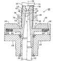
図1には本発明の一実施形態にかかる異形缶製造方法において特徴的なエキスパンド成形工程を行う際に用いられる分割金型(エキスパンド型)の概略構成が示されている。なお、本実施形態では、分割金型の外周壁の上部に上部逃がし部を設け、かつ該外周壁の下部に下部逃がし部を設けた例について説明する。
本実施形態においては、缶胴上端10a及び缶胴下端10b側が開口している円筒状缶部材10(同図(A)参照)の内側に、例えば缶胴下端10b側より分割金型12(同図(B)参照)を挿入する。
【0025】
そして、同図(C)に示すような分割金型12の拡径により、缶部材10の缶胴14のエキスパンド成形を行い、同図(D)に示すような缶胴拡径部16を缶部材10の缶胴14に形成している。
すなわち、同図(C)では、分割金型12の中心軸線に沿って開けられている穴18に、セグメント拡径用クサビ軸(以下、クサビ軸という)20を下方より入れて、図中矢印i方向に上昇させることにより、分割金型12を構成する各エキスパンド成形用セグメント12a〜12jは、半径方向外側である図中矢印j方向に拡径する。
【0026】
このような各エキスパンド成形用セグメント12a〜12jの拡径により、まず缶部材10の缶胴拡径部16の上部になる部分の全周に渡って上部略タガ状凸部22aの成形と、缶部材10の缶胴拡径部16の下部になる部分の全周に渡って下部略タガ状凸部22bの成形が同時に始まる。
また缶部材10の缶胴14の上部略タガ状凸部22aと下部略タガ状凸部22bになる部分との間に、螺旋状の傾斜凹凸模様24が成形される。
【0027】
ここで、各エキスパンド用セグメント12a〜12jの半径方向外側への拡径量を調整することにより、同図(D)に示すような缶胴上部14a及び缶胴下部14bよりも大径の缶胴拡径部16を缶部材10の缶胴14に形成している。
本実施形態において特徴的なことは、缶胴拡径部16に、上部略タガ状凸部22aと、下部略タガ状凸部22bと、傾斜凹凸模様24を設けたことである。
【0028】
上部略タガ状凸部22aは、缶部材10の缶胴拡径部16の上端に相当し、該缶胴拡径部16上部の全周に渡って設けられている。
下部略タガ状凸部22bは、缶部材10の缶胴拡径部16の下端に相当し、該缶胴拡径部16下部の全周に渡って設けられている。
傾斜凹凸模様24は、缶部材10の缶胴拡径部16の上部略タガ状凸部22aから下部略タガ状凸部22bにかけて形成された傾斜凹模様26、傾斜凸模様28を含む。
【0029】
そして、傾斜凹凸模様24を構成する傾斜凹模様上端部26aを上部略タガ状凸部22aよりも下方で、且つ半径方向内側に位置させている。これにより傾斜凹模様26の上端部26aと缶部材10の缶胴上部14aとを、上部略タガ状凸部22aにより隔絶している。
また傾斜凹模様下端部26bを下部略タガ状凸部22bよりも上方で、且つ半径方向内側に位置させている。これにより缶部材10の缶胴下部14bと傾斜凹模様26の下端部26bとを、下部略タガ状凸部22bにより隔絶している。
【0030】
エキスパンド装置
図2には本発明の一実施形態にかかる分割金型を用いたエキスパンド装置の概略構成が示されている。
なお、同図においては、中心軸線29よりも左側の断面図は分割金型を半径方向外側に拡径した後の説明図、中心軸線29よりも右側の断面図は、同様の分割金型を半径方向外側に拡径する前の説明図である。
同図に示すエキスパンド装置30は、前記クサビ軸20と、前記分割金型12と、金型保持体32と、缶押えガイド34と、缶ホールド36を備える。
【0031】
クサビ軸20の外周壁、分割金型12の内周壁には、それぞれテーパ部38,40が設けられている。クサビ軸20は、そのテーパ部38が分割金型12のテーパ部40と摺動しながら上下動する。
分割金型12は、エキスパンド成形を行う略円筒状の成形部42と、該成形部42の下部に設けられ、金型保持体32に保持される略円盤状の保持部44を備える。
すなわち、金型保持体32は、例えば略ドーナツ状の上部保持部46と、略ドーナツ状の下部保持部48を備え、分割金型12の保持部44を保持している。
【0032】
分割金型12の保持部44の外周壁には横向きに穴50が設けられ、該穴50にばね52の一端が設けられている。ばね52の他端は上部保持部46の内周壁に設けられている。
缶押えガイド34は、ばね(図示省略)等の力により缶部材10の上端を上方より押し付ける。
缶ホールド36は、ばね(図示省略)等の力により、缶胴を側方より保持し、缶部材10の分割金型12への供給、及び缶部材10の分割金型12よりの排出を行わせる。
【0033】
この結果、クサビ軸20を上下方向に移動させることにより、分割金型12を半径方向に移動させることができる。
すなわち、エキスパンド成形の際には、中心軸線29よりも左側の縦断面図に示されるように缶押えガイド34により缶部材10の上端をしっかり押えた状態で、クサビ軸20を上方向に移動させる。すると、クサビ軸20のテーパ部38は分割金型12のテーパ部40を押すので、分割金型12は半径方向外側に移動する。これにより分割金型12の外周壁による缶部材10のエキスパンド成形が進む。
【0034】
これに対し、クサビ軸20を下方に移動させることにより、ばね52の反力により分割金型12は半径方向内側に移動する。これにより例えばエキスパンド装置30に対しエキスパンド成形前の缶部材10を容易にセットすることができる。
【0035】
分割金型
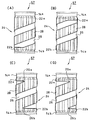
図3には本発明の一実施形態にかかる分割金型12の保持部44を省略した概略構成が示されている。
なお、同図(A)は本実施形態にかかる分割金型12の外観斜視図、同図(B)は該分割金型12を上方より見た図、同図(C)は該分割金型12を側方より見た図である。図1では金型を10分割した分割金型を用いた例について説明したが、同図では金型を12分割した分割金型12を用いた例について説明する。
【0036】
同図に示す分割金型12は、円筒状の缶部材10内に配置され、該缶部材10の缶胴拡径部になる部分をその内側から半径方向外側にエキスパンド成形し、缶胴上部及び缶胴下部よりも大径の缶胴拡径部とするための外周壁を持つ。
その外周壁に、上部逃がし部54aと、下部逃がし部54bと、拡径対応部56を一体的に備える。拡径対応部56に、上部タガ対応部58aと、下部タガ対応部58bと、傾斜凹凸模様対応部60を設ける。
【0037】
傾斜凹凸模様対応部60は、傾斜凹模様対応部62と、傾斜凸模様対応部64を含む。
そして、本実施形態においては、傾斜凹模様対応部62の上端部62a(図3(C)参照)の位置を上部タガ対応部58aよりも下方、且つ半径方向内側に位置させることにより、傾斜凹模様対応部62の上端部62aと上部逃がし部54aとを、上部タガ対応部58aにより隔絶している。
【0038】
また本実施形態においては、傾斜凹模様対応部62の下端部62bの位置を下部タガ対応部58bよりも上方、且つ半径方向内側に位置させることにより、傾斜凹模様対応部62の下端部62bと下部逃がし部54bとを、下部タガ対応部58bにより隔絶している。
ここで、上部逃がし部54aは、分割金型12外周壁の半径方向外側への拡径によっても缶部材の缶胴上部になる部分を拡径させない外径をもち、缶部材の缶胴上部になる部分に、拡径させない上部非拡径部を設けるためのものとする。
【0039】
下部逃がし部54bは、分割金型12外周壁の半径方向外側への拡径によっても缶部材の缶胴下部になる部分を拡径させない外径をもち、缶部材の缶胴下部になる部分に、拡径させない下部非拡径部を設けるためのものとする。
拡径対応部56は、分割金型12外周壁の上部逃がし部54aから下部逃がし部54bにかけて形成され、逃がし部54a,54bよりも大きな径をもち、缶部材の缶胴上部になる部分から缶胴下部にかけて、内側から半径方向外側に押圧して拡径し、所定の寸法を持つ缶胴拡径部を成形するためのものとする。
【0040】
上部タガ対応部58aは、分割金型12外周壁の拡径対応部56の上部に相当し、該拡径対応部56の上部の全周に渡って設けられる。
下部タガ対応部58bは、分割金型12外周壁の拡径対応部56の下部に相当し、該拡径対応部56の下部の全周に渡って設けられる。
傾斜凹凸模様対応部60は、分割金型12外周壁の上部タガ対応部58aから下部タガ対応部58bにかけて、分割金型12外周壁の円周方向に対し斜めに形成された傾斜凹模様対応部62、傾斜凸模様対応部64を含む。
【0041】
なお、本実施形態においては、分割金型12はその中心軸線を中心に複数のエキスパンド用セグメント12a〜12lに分割されている。
各エキスパンド用セグメント12a〜12lは、それぞれ分割金型12外周壁の対応部を持つ。
そして、隣合うエキスパンド用セグメント12a〜12lに形成されている各傾斜凹凸模様対応部は、実質的に連続しており、本実施形態においては、螺旋状に形成されている。
【0042】
本実施形態にかかる分割金型12は概略以上のように構成され、以下にその作用について説明する。
従来、円筒状缶部材の缶胴をエキスパンド成形し、その缶胴面に螺旋状の傾斜凹凸模様を成形しようとすると、缶胴の開口端部の断面円形が歪んでしまう。特に金属缶が溶接缶であると、溶接缶胴(メガネ缶)の断面は完全な円形ではないので、その歪みを助長させやすくなる。この状態で、缶胴の開口端部をフランジ成形すると、フランジの長さにバラツキが生じる。例えば許容範囲0.2mmに対し、それよりも大きい0.3mmのバラツキが生じ、巻締密封不良を起こし、品質上、重大欠陥につながるおそれがある。
【0043】
このようにフランジの長さにバラツキが生じる原因を調査したところ、金型で拡径する際に、缶胴の開口端に近い部分では、缶胴面に傾斜模様を浮き出させるための傾斜凸模様対応部64を備えたエキスパンド用セグメントが、隣接する螺旋状の傾斜凹模様対応部62を備えたエキスパンド用セグメントよりも先に缶部材の缶胴内面に当接し、これにより、傾斜凸模様対応部64で缶胴内面が鋭角的に拡径されるので、エキスパンド成形された缶胴の開口端の円形が歪んでしまうことがわかった。
そして、このように開口端部が歪んだままフランジ成形すると、フランジャーロールが不均一に開口端内面に当たる結果、短径側のフランジ長さが長くなる傾向があることが判明した。
【0044】
そこで、本実施形態においては、分割金型12の拡径対応部56に、上部タガ対応部58a、下部タガ対応部58bを設け、上部タガ対応部58aから下部タガ対応部58bにかけて、傾斜凹凸模様対応部60を設けている。
この結果、傾斜凹模様対応部62の上端部62aの位置を上部タガ対応部58aよりも下方、且つ半径方向内側に位置させることにより、傾斜凹模様対応部62の上端部62aと上部逃がし部54aとを、上部タガ対応部58aにより隔絶している。
【0045】
また傾斜凹模様対応部62の下端部62bの位置を下部タガ対応部58bよりも上方、且つ半径方向内側に位置させることにより、該傾斜凹模様対応部62の下端部62bと下部逃がし部54bとを、下部タガ対応部58bにより隔絶している。
このような分割金型12を用いることにより、缶部材10は次のようにエキスパンド成形されることとなる。
【0046】
すなわち、本実施形態において、エキスパンド成形工程では、缶部材の缶胴拡径部上部になる部分の全周に渡って設けられる上部略タガ状凸部と、該缶部材の缶胴拡径部下部になる部分の全周に渡って設けられる下部略タガ状凸部のエキスパンド成形後の拡径寸法が、前記上部略タガ状凸部及び下部略タガ状凸部との間において、円周方向に対し斜めに設けられる傾斜凹凸模様の傾斜凹模様の径よりも大となるように、缶部材をエキスパンド成形する。
この結果、このような成形方法の工夫のないものに比較し、缶胴の変形歪みの発生そのものを大幅に低減することができる。
【0047】
すなわち、缶胴の円周方向に凹凸模様を成形する場合に比較し、缶胴の円周方向に対し傾斜凹凸模様を成形する場合は缶胴の変形歪みが発生しやすい。
これに対し、本実施形態のように傾斜凹凸模様の傾斜凹模様の径よりも、缶胴の円周方向の全周に渡って缶胴の変形歪みを発生しにくい略タガ状凸部を半径方向外側に突出させて形成することにより、傾斜凹凸模様の成形の際に、缶胴の開口端における変形歪みの発生そのものを大幅に低減できるからである。
【0048】
しかも、缶部材10は、傾斜凹模様26の上端部26aと缶胴上部14aとを上部略タガ状凸部22aにより隔絶し、該傾斜凹模様26の下端部26bと缶胴下部14bとを下部略タガ状凸部22bにより隔絶する。
したがって、缶胴拡径部16に傾斜凹凸模様24を成形する際に、缶胴の変形歪みが多少生じても、略タガ状凸部22a,22bの成形により、その成形歪みを缶胴上端10a、缶胴下端10b方向へ伝播させないようにするか、あるいは矯正される。これにより、円筒形の缶胴上端10a、缶胴下端10bに変形歪みが発生するのを防ぐことができる。
【0049】
このように本実施形態にかかる異形缶製造方法、及び分割金型12によれば、缶部材10の缶胴14に装飾効果に優れた傾斜凹凸模様24を成形することにより、缶部材10に定形的な外観模様に加えて傾斜模様を施すことができるので、色々な組み合せにより外観デザインに種々の変化をもたすことができる。これにより、定形模様のものに比較し、外観性にバリエーションをもたせ、他の商品との差別化を図ることができる。
【0050】
しかも、本実施形態においては、傾斜凹凸模様24を成形する際に、缶胴拡径部16の両端部に略タガ状凸部22a,22bを設けるという簡単でしかも安価な構成により、傾斜模様の成形に伴う成形歪みが缶胴14の開口端部10a,10bに及ぼす影響を可及的に少なくすることができる。したがって、このような円形の開口端部10a,10bをフランジ成形しても、フランジの長さのバラツキを例えば製造許容範囲の0.2mm以下にすることができるので、巻締密封不良缶の発生を防止することができる。
【0051】
<傾斜凹模様の連続性>
本実施形態においては、複数のエキスパンド用セグメントを用いているので、該隣合うエキスパンド用セグメントの傾斜凹模様対応部が、実質的に連続することも非常に重要である。
すなわち、傾斜凹模様の成形時の変形歪みは、傾斜凹模様を不連続に成形すると、不連続な傾斜凹模様毎に、その影響を大きく受ける。これに対し、傾斜凹模様が連続していれば、不連続な傾斜凹模様の成形時に比較し、このような変形歪みの影響が小さくすむからである。
【0052】
<上部逃し部>
分割金型としては、分割金型12の缶胴上部に対応する部分に逃がし部、すなわち上部逃がし部54aを設けないものも用いることができる。
しかしながら、図3に示すように分割金型12の外側壁に上部逃がし部54aと下部逃がし部54bを設けることが、上部逃がし部54aを設けず、下部逃がし部54bのみを設けるものに比較し、略タガ状凸部から缶胴端部にかけて、内面の傷付きを防いで前記エキスパンド成形が安定して行える点で、内面品質上好ましい。
【0053】
<フランジ成形後の缶部材>
缶部材10を前述のようにエキスパンド成形した後に、フランジ成形した後の様子を図4示す。
本実施形態にかかる異形缶製造方法、分割金型によれば、断面円形の開口端部10a,10bをフランジ成形することができるので、同図に示されるようなフランジ66a,66bの長さのバラツキを許容範囲内、例えば0.2mm以下にすることができる。これにより、巻締密封不良缶の発生を防止することができる。
同図に示されるようなフランジャー工程後の缶部材10に対し、シーマー工程等を行い、缶胴の一方の開口端に缶蓋を設け、内容物を充填した後に、缶胴の他方の開口端に缶底を設けると、次のような異形缶を製造することができる。
【0054】
異形缶
図5〜6には本発明の一実施形態にかかる分割金型、異形缶製造方法により製造された異形缶の概略構成が示されている。
なお、図5(A)は本実施形態にかかる異形缶の平面図、図5(B)は該異形缶の底面図、図5(C)は該異形缶の縦断面を内面側より見た図である。また図6(A)は該異形缶の背面図、図6(B)は該異形缶の左側面図、図6(C)は該異形缶の正面図、図6(D)は該異形缶の右側面図である。
【0055】
同図に示す異形缶67は、前記エキスパンド成形後の缶部材10の上端10a、下端10bにそれぞれ缶蓋68、缶底70が設けられたものであり、缶胴上部14a及び缶胴下部14bは、それぞれ拡径していない上部非拡径部、下部非拡径部である。缶胴上部14aの上部非拡径部から缶胴下部14bの下部非拡径部にかけて半径方向外側に拡径している。これを缶胴拡径部16としている。
本実施形態においては、缶胴拡径部16に上部略タガ状凸部22aと、下部略タガ状凸部22bと、螺旋状の傾斜凹凸模様24を備える。
【0056】
そして、傾斜凹凸模様24を構成する傾斜凹模様26の上端部26aの位置を上部略タガ状凸部22aよりも下方、且つ半径方向内側に位置させることにより、傾斜凹模様26の上端部26aと缶胴上部14aとを上部略タガ状凸部22aにより隔絶している。
かつ傾斜凹模様26の下端部26bの位置を下部略タガ状凸部22bよりも上方、且つ半径方向内側に位置させることにより、傾斜凹模様26の下端部26bと缶胴下部14bとを下部略タガ状凸部22bにより隔絶している。
【0057】
ここで、上部略タガ状凸部22aは、缶胴拡径部16の上部に相当し、該缶胴拡径部16の上部の全周に渡って設けられている。
また、下部略タガ状凸部22bは、缶胴拡径部16の下部に相当し、該缶胴拡径部16の下部の全周に渡って設けられている。
傾斜凹凸模様24は、缶胴16の上部略タガ状凸部22aから下部略タガ状凸部22bにかけて、該缶胴16の円周方向に対し斜めに形成された傾斜凹模様26、傾斜凸模様28を含む。
【0058】
これにより異形缶67は、定形的な外観模様にバリエーションを加えて、変化に富んでおもしろ味のある傾斜凹凸模様24を持つので、缶胴14の装飾効果を向上させ、容器の形状等の点で他の商品との差別化を図ることができる。
しかもこのような装飾効果に優れた異形缶67は、本実施形態にかかる金型12、異形缶製造方法により製造されることにより、従来解決することが困難であった、缶胴14に傾斜凹凸模様24を形成する際の開口端10a,10bの成形歪みの発生が大幅に低減されている。
【0059】
<螺旋巻数>
異形缶67においては、螺旋状凹凸模様24の螺旋巻数の選定は非常に重要であり、本実施形態においては、螺旋状凹凸模様24の螺旋巻数を整数倍とすることが好適である。このために本実施形態では2巻構成で螺旋状凹凸模様24が成形されている。
すなわち、傾斜凹凸模様24が螺旋状に形成された場合、その巻数を整数倍とすることにより、傾斜凹凸模様24による成形応力が円周方向で均等に作用し、缶胴14の変形歪みを更に防ぎ、またエキスパンド成形との相乗効果により側壁強度を増加させることができ、板厚のゲージダウン化に有利となる。
【0060】
また異形缶67に内容物を充填した缶詰を加熱殺菌する際に、隣合う缶67との隙間がなく密接触していても、缶胴拡径部16に形成された傾斜凹凸模様24の傾斜凹模様26を伝わってスチームや冷却水が通過し易く、また缶胴14の中央に行き渡り易く、従来のような定形模様が施された異形缶よりも加熱効率や冷却効率を更に向上させることができる。
【0061】
<略タガ状凸部の位置>
略タガ状凸部22a,22bの位置の選定は、異形缶67の既存の設備に対する適応性の向上の点から非常に重要である。
すなわち、略タガ状凸部22a,22bの好適な位置に関し、本発明者らは、例えば202径の円筒缶用の既存の設備では、缶胴上端、缶胴下端からそれぞれ缶高の10%以上、20%以下の位置で、缶を支えている点に着目した。
そして、異形缶67の缶胴14であっても、前記好適な範囲内に、異形缶67の略タガ状凸部22a,22bが位置し、ほぼ同径寸法とすれば、円筒缶用の設備上で異形缶を支えることができるので、異形缶67の缶胴を既存の円筒形の缶胴と同様に扱うことができることがわかった。
【0062】
そこで、本実施形態においては、異形缶において、缶胴14の上端部と上部略タガ状凸部22a間の上下方向の長さ、すなわち略タガ状凸部22aの位置を缶高の10%以上、20%以下とする。また缶胴14の下端部と下部略タガ状凸部22b間の上下方向の長さ、すなわち略タガ状凸部22aの位置を缶高の10%以上、20%以下とする。そして、略タガ状凸部22a,22bの外径をほぼ同径とすることが好ましい。
【0063】
例えば本実施形態においては、缶高約104.7mmの異形缶67に対しては、上部略タガ状凸部22aを異形缶67の上端部から約15mmの位置に成形し、下部略タガ状凸部22bを異形缶67の下端部から約15mmの位置に成形している。また異形缶67では、外径を例えば52.74mmとしている。これにより円筒缶用の設備は異形缶67を缶胴14の略タガ状凸部22a,22bで支えることができる。
したがって、本実施形態においては、異形缶67の缶胴14を通常の円筒缶の缶胴と同様に扱うことができるので、ほぼそのまま円筒缶用の既存の設備を用いることができる。
【0064】
また略タガ状凸部22a,22bの位置が缶胴上端、缶胴下端からそれぞれ、缶高の10%よりも近い位置に設けられていると、異形缶67の略タガ状凸部22a,22bと202径の円筒缶用の設備とが干渉してしまう。特に202径の円筒缶用のフランジャー、シーマー等の設備への適応性が低下してしまうことがある。
【0065】
これに対し、略タガ状凸部22a,22bが缶胴上端、缶胴下端からそれぞれ、缶高の20%よりも高い位置に設けられていると、略タガ状凸部22a,22bでの転がり時の略タガ状凸部22a,22bを支えられなくなり、安定性が悪くなる。例えば自動販売機内において略タガ状凸部で直線的に転がりにくくなり、円筒缶の缶胴と同様に扱うことができなくなることがあるからである。
このような点からも、本実施形態においては、略タガ状凸部22a,22bの上下方向の位置はそれぞれ缶胴上端、缶胴下端からそれぞれ缶高の10%以上、20%以下に位置することが非常に好ましい。
【0066】
変形例
なお、本発明は前記各構成に限定されるものではなく、発明の要旨の範囲内であれば、種々の変形が可能である。
【0067】
<傾斜凹凸模様>
缶胴にエキスパンド成形される傾斜凹凸模様のバリエーションとしては、傾斜凹模様対応部が形成されたエキスパンド用セグメントを1つ以上飛びに配置し、螺旋模様を不連続的に形成してもよいが、前述のような加熱殺菌処理上の観点から、エキスパンド成形用セグメントの螺旋状の傾斜凹模様対応部を連続的に配置して螺旋模様を缶胴に形成するようにすることが、より好ましい。
また傾斜凹凸模様は、傾斜リング模様、複数条の螺旋模様、上下に区分した傾斜凹凸模様、あるいは傾斜凹凸模様をクロスした模様等の傾斜凹凸模様、またはそれらの組合せ模様を形成することに適用することもできるが、前述のような加熱殺菌処理上、側壁強度の観点から、螺旋状がより好ましい。
【0068】
また前記実施形態では、絞りしごき成形した缶、薄肉化深絞り成形した缶、ボトル型に成形した缶等にも適用ができるが、円形歪みを生じやすい溶接缶への適用が、成形不良の低減の効果が顕著に得られることから、より効果的である。
また前記構成では、エキスパンド成形により、上部タガ状凸部22a、下部タガ状凸部22b及び傾斜凹凸模様24の傾斜凸模様が同径で、半径方向外側に張出している缶部材を得た例について説明した。しかしながら、本発明はこれに限定されるものではなく、成形歪みが防げるものであれば、以下に示すような缶部材とすることも可能である。
【0069】
すなわち、本発明の缶部材としては、略タガ状凸部が、傾斜凹凸模様の傾斜凹模様よりも半径方向外側に張出すものであれば、例えば上部タガ状凸部及び下部タガ状凸部が同径で、傾斜凹凸模様の傾斜凸模様よりも、半径方向外側に張出しているような缶部材とすることや、上部タガ状凸部及び下部タガ状凸部が同径で、傾斜凹凸模様の傾斜凸模様が上部タガ状凸部及び下部タガ状凸部よりも半径方向外側に張出している缶部材とすることも可能である。
【0070】
【実施例】
以下、本発明の好適な実施例を説明する。なお、本発明は実施例に限定されるものではない。
本実施例にかかる異形缶の製造方法の一例を示す。
まず本実施例にかかるエキスパンド成形工程の前に、フォーミング、溶接を行う。
【0071】
すなわち、フォーミングでは、予め外面に装飾や商標等が印刷され、内面に防食処理がなされた長方形の熱可塑性樹脂被覆鋼板(例えば厚さ0.22mm、縦108.7mm、横158.2mm)を円筒形に丸める。
前記フォーミング後に溶接を行う。
すなわち、円筒形に丸められた鋼鈑の端部を僅かに重ね合わせ、その重合部を溶接機の銅線電極で挟み、電気抵抗溶接する。これを円筒状の缶部材(外径約50.44mm)とする。
【0072】
ここで、一般的な溶接機は、通常202径までの仕様であるが、本実施例においては、200径の缶部材が溶接できるものを用いているので、異形缶の形状に対する選択が増える。
これにより、例えばエキスパンド成形工程では、缶部材の外形を202径とすることができる。また本実施例においては、缶部材のネックを202径では成形できなかった113径よりも小さい径に成形することができるので、缶部材の開口端部に、より小さな蓋を装着することができる。
【0073】
前記溶接された重合部の内外面をポリエステルフィルムあるいは補正塗料で被覆する防食処理した後の缶部材に対し、本実施例において特徴的なエキスパンド成形工程(図1等参照)を行う。
すなわち、エキスパンド成形工程では、円筒状缶部材の内側に分割金型を挿入し、該分割金型を一斉に半径方向外側に押し広げ、各分割金型の外周壁の形状を円筒状缶部材の缶胴に移している。
【0074】
ここで、エキスパンド成形工程では、缶部材の傾斜凹凸模様に対応する傾斜凸模様部分と拡径部の上部略タガ状凸部及び下部略タガ状凸部に対応する部分の成形を同時に開始し、次に拡径部の上部略タガ状凸部及び下部略タガ状凸部になる部分との間に、缶部材の傾斜凹模様が僅かに遅れて成形される。
このため、本実施例においては、缶胴の変形歪みの発生そのものを大幅に低減している。しかも、本実施例においては、傾斜凹凸模様を形成する際に、缶胴の成形歪みが生じても、成形歪みの缶胴開口端部への伝播を上部略タガ状凸部及び下部略タガ状凸部で遮断することができる。したがって、本実施例においては、円筒形の開口端部に歪みが発生するのを防ぐことができる。これにより、本実施例においては、缶の装飾効果の向上と、成形の際に発生し易い変形歪みの缶胴開口端部への影響を低減することができる。
【0075】
ここで、缶部材の上部非拡径部と下部非拡径部の外径は、円筒状の缶部材の拡径前の外径のままの約50.44mmとなっている。
一方、略タガ状凸部の頂点の外径は、それぞれ同一の外径を有しており、約52.74mmまで拡径されている。また予定缶高約104.7mmに対し、缶部材の上部端面から上部略タガ状凸部の最大エキスパンド部(最大拡径部)までの距離、及び缶部材の下部端面から下部略タガ状凸部の最大エキスパンド部までの距離はそれぞれ、約15mm以上、18mm以下の範囲内に入っている。
【0076】
つぎに、このように成形された缶部材の両端に、フランジャーでフランジを形成すると、本実施例の缶部材(図4等参照)が得られる。
そして、缶部材のフランジの一方に、タブを引き上げ弱化線で囲まれた口部を破断し開口する金属製の缶蓋をシーマーで装着させる。このとき、異形缶のフランジに装着された蓋の外径は、約52.3mmになっている。
【0077】
この後、蓋を装着させた缶部材に底側開口端より清涼飲料等を充填し、充填後に該底側開口端部のフランジに底蓋を装着し、異形缶詰が製造される(図5,6等参照)。このとき、底蓋の外径も蓋の外径と同様に約52.3mmになっている。底蓋の下面から蓋の上面までの高さ(缶高)は、104.7mmとなっており、内容量は182mlとなっている。
このように本実施例においては、缶胴の元径を200径とし、現行202径190ml缶のネック径と同じとしているので、フランジ加工をすれば、蓋巻締め部が、現行缶、例えば202径190ml缶とほぼ同じ形状となる。
【0078】
この結果、本実施例にかかる異形缶は、その略タガ状凸部が既存の設備において一般的な円筒缶の胴部と同じ作用を持つ。これにより本実施例にかかる異形缶の製造の際に、一般的な円筒缶用の充填機、フランジャー、シーマー等の既存の設備を大幅に改造することなく用いることができる。
また客先の円筒缶用の設備を大幅に改造をすることなく、本実施例にかかる異形缶を、一般的な202径の円筒缶とほぼ同様に取り扱うことができる。
【0079】
例えば自動販売機に一般的な202径190mlの円筒缶と同じように入れることができる。また製缶会社においては、新たに製造設備を設ける際、ネック設備は不要となる。
したがって、本実施例にかかる異形缶製造方法、及び異形缶は、既存の円筒缶用の設備に対し適用可能にされる。
【0080】
【発明の効果】
以上説明したように本発明にかかる異形缶製造方法によれば、エキスパンド成形工程において、上部逃がし部及び下部逃がし部と、上部タガ対応部と、下部タガ対応部と、凹凸模様対応部とを備え、前記傾斜凹凸模様対応部を螺旋状とし、その螺旋巻数を正の整数倍とし、且つ前記傾斜凹凸模様対応部の凹部の上端を前記上部タガ対応部よりも下方、且つ半径方向内側に位置させ、該凹部の下端を前記下部タガ対応部よりも上方、且つ半径方向内側に位置させ、前記傾斜凹凸模様対応部の凹部が、前記上部タガ対応部及び下部タガ対応部によって、前記上部逃がし部及び下部逃がし部と隔絶しているエキスパンド型を用いて、該円筒状缶部材の缶胴になる部分をエキスパンド成形することとしたので、缶の装飾効果の向上と同時に、成形の際に発生し易い変形歪みの缶胴開口端部への影響を低減することができる。
また本発明にかかるエキスパンド型においては、傾斜凹凸模様対応部が螺旋状であり、その螺旋巻数が正の整数倍であることにより、前記変形歪みの発生を更に低減することができる。
【図面の簡単な説明】
【図1】本発明の第一実施形態にかかるエキスパンド型によるエキスパンド成形工程の説明図である。
【図2】本発明の一実施形態にかかるエキスパンド型を用いたエキスパンド装置の概略構成の説明図である。
【図3】本発明の一実施形態にかかるエキスパンド型の概略構成の説明図である。
【図4】本発明の一実施形態にかかるエキスパンド成形工程後にフランジ成形した缶部材の説明図である。
【図5】本発明の一実施形態にかかる異形缶の概略構成の説明図である。
【図6】本発明の一実施形態にかかる異形缶の概略構成の説明図である。
【符号の説明】
10 缶部材
12 分割金型(エキスパンド型)
14a 缶胴上部
14b 缶胴下部
16 缶胴拡径部
22a 上部略タガ状凸部
22b 下部略タガ状凸部
24 傾斜凹凸模様
26 傾斜凹模様
28 傾斜凸模様
67 異形缶[0001]
BACKGROUND OF THE INVENTION
The present invention is a method for producing a modified can,as well asExpandMold,In particular, the present invention relates to a technique capable of simultaneously improving the decorative effect of a can and reducing the occurrence of deformation distortion during molding.
[0002]
[Prior art]
For example, in beverage cans, three-piece cans and two-piece cans such as deep-drawn cans and squeezed iron cans are generally manufactured.
Since these cans have almost the same shape, they can be produced in large quantities and at low cost. However, since these cans have no individuality in shape, the products themselves could not be easily distinguished by shape.
For this reason, for the purpose of individualizing and differentiating products, it is desired to develop cans that have unique shapes and are inexpensive.
[0003]
In order to meet such a demand, for example, a deformed can having a larger diameter of the can body than the upper portion of the can body and the lower portion of the can body can be considered (see, for example, Patent Document 1 and Patent Document 2).
For example, a can body widened portion is formed by disposing a mold having concaves and convexes of the same shape in a cylindrical can member and expanding the can member with the mold.
[0004]
[Patent Document 1]
JP 49-28492 A
[Patent Document 2]
JP 59-163041 A
[0005]
[Problems to be solved by the invention]
However, even in the deformed can, the pattern formed on the can body has the same shape in the circumferential direction and is shaped, and further variations are required.
When the present inventors examined improvement of the decoration effect of a can, it turned out that shaping | molding an inclined uneven | corrugated pattern in a can body is excellent in the balance of a cost versus the decoration effect.
However, if an inclined concavo-convex pattern is to be formed in the portion of the cylindrical can member that becomes the can body, distortion occurs in the portions that become both ends of the can body, so the length of the flange formed at the open end of the can body Variations occur. In particular, in a welded can, the opening end of the can body is difficult to be formed into a perfect circle due to the weld seam, and therefore distortion at both ends of the can body is likely to occur.
[0006]
Such a variation in the length of the flange is likely to cause a winding tight seal failure even if it is about 0.3 mm. In making cans, it was very important to reduce the occurrence of distortion at both ends of the can body.
However, since there is no appropriate technique that can reduce the occurrence of distortion at both ends of the can body, it has not been practically used to form an inclined uneven pattern on the can body. is there.
[0007]
In addition, even for such a can, it is important that the equipment for the existing cylindrical can is not changed, and it is also important to be put in the vending machine in the same manner as the existing cylindrical can. It was important to ensure adaptability to such existing facilities.
The present invention has been made in view of the above-mentioned problems of the prior art, and a first object thereof is to simultaneously improve the decorative effect of the can and reduce the occurrence of deformation distortion that easily occurs during molding. Modified can manufacturing method,as well asExpandMoldTo provideThe
[0008]
[Means for Solving the Problems]
As a result of intensive studies on the above problems by the present inventors, first, the generation mechanism of distortion at the open end of the can body was found. In other words, compared to the case of forming a general concavo-convex pattern, when forming an inclined concavo-convex pattern having an excellent decorative effect, deformation distortion of the can body is particularly likely to occur, and the deformation distortion is caused by the opening of the can body. It is easy to propagate to the edge.
[0009]
Furthermore, the present inventors have examined a forming technique of an inclined uneven pattern capable of reducing the occurrence of deformation distortion of the can body as much as possible. Then, each of the convex portions is molded, an inclined concave pattern is formed between the convex portions, and the convex portion is projected outward in the radial direction from the inclined concave pattern. It was found that the deformation itself of the can body can be greatly reduced. Furthermore, even if deformation deformation of the can body occurs, it has also been found that propagation to the end portion of the can body opening is blocked by the convex portions at both ends of the enlarged diameter portion, and the present invention has been completed.
[0010]
That is, in order to achieve the first object, the modified can manufacturing method according to the present invention is a modified can manufacturing method including an expanding molding step.
The expand molding process includes an upper relief portion and a lower relief portion corresponding to a can barrel upper end portion and a can barrel lower end portion that do not expand, and a portion from the upper portion of the can member to a lower portion of the can barrel from the inside. The outer peripheral wall is provided with an enlarged diameter corresponding portion for expanding the diameter of the portion of the can member that is pressed radially outward and becomes a can barrel enlarged portion having a predetermined dimension, and is adapted for the diameter expansion. The portion corresponds to an upper portion of the diameter expansion corresponding portion, corresponds to an upper tag corresponding portion provided over the entire circumference of the upper portion of the diameter expansion corresponding portion, and a lower portion of the diameter expansion corresponding portion, and the diameter expansion corresponding portion A lower tag corresponding portion provided over the entire circumference of the upper portion, and at least a recess formed in an oblique direction with respect to the circumferential direction of the outer peripheral wall from the upper tag corresponding portion of the outer peripheral wall to the lower tag corresponding portion. Including an inclined uneven pattern corresponding part,The inclined concavo-convex pattern corresponding part is spiral, and the number of spiral turns is a positive integer multiple,In addition, the upper end of the concave portion of the inclined concavo-convex pattern corresponding portion is positioned lower than the upper tag corresponding portion and radially inward, and the lower end of the concave portion is positioned higher than the lower tag corresponding portion and radially inward. In the can body of the cylindrical can member, an expanded mold in which the concave portion of the inclined concavo-convex pattern corresponding portion is isolated from the upper escape portion and the lower escape portion by the upper tag corresponding portion and the lower tag corresponding portion. The part to be expanded is formed.
[0011]
Here, the expansion molding is performed by expanding the portion of the cylindrical can member that becomes the diameter of the can body from the inside to the outside in the radial direction, so that the can can be larger in diameter than the upper end of the can body and the lower end of the can body. The body diameter is increased.
Further, in order to achieve the first object, the expandable mold according to the present invention is disposed in a cylindrical can member, and a portion that becomes a can body enlarged diameter portion of the can member is expanded from the inside to the outside in the radial direction. In the expand type having an outer peripheral wall for making the can body enlarged diameter part larger than the can body upper end part and the can body lower end part,
The outer peripheral wall includes an upper escape portion and a lower escape portion, an enlarged diameter corresponding portion, an upper tag corresponding portion, a lower tag corresponding portion, and an inclined uneven pattern corresponding portion. And the upper end of the recessed part of an inclination uneven | corrugated pattern corresponding | compatible part is located below the said upper tag corresponding | compatible part, and a radial inside.Furthermore, the inclined concavo-convex pattern corresponding part is spiral, and the number of spiral turns is a positive integer multiple,And the lower end part of the recessed part of this inclination uneven | corrugated pattern corresponding | compatible part is located above the said lower tag corresponding | compatible part, and is located inside a radial direction, It is characterized by the above-mentioned.
[0012]
Here, the said diameter expansion corresponding | compatible part presses from the inside which becomes the can body lower part to the part which becomes the can body lower part from the inside to the radial direction outside, and becomes a can body enlarged diameter part with a predetermined dimension. Up to the diameter of the portion of the can member that becomes the can body.
The upper tag corresponding portion corresponds to an upper portion of the diameter expansion corresponding portion of the outer peripheral wall, and is disposed on the entire circumference of the upper portion of the diameter expansion corresponding portion.CottonIs provided.
[0013]
The lower tag corresponding portion corresponds to a lower portion of the diameter expansion corresponding portion of the outer peripheral wall, and is disposed on the entire circumference of the lower portion of the diameter expansion corresponding portion.CottonIs provided.
The inclined concavo-convex pattern corresponding portion is inclined with respect to the circumferential direction of the outer peripheral wall on the outer peripheral wall from the upper tag corresponding portion to the lower tag corresponding portion.In the directionAt least an inclined uneven pattern is formedRecessincluding.
[0014]
The slope hereUnevennessPattern corresponding partOf the recessPositioning the upper end below the upper tag corresponding part and radially inwardly means that the upper tag corresponding part is located on the outer shell of the outer wall.endPart corresponding to the part and slopeUnevennessPattern corresponding partOf the recessThis means isolating the top edge.
The slope hereUnevennessPattern corresponding partOf the recessWhen the lower end portion is positioned above the lower tag corresponding portion and radially inward, the lower tag corresponding portion is inclined with the portion corresponding to the lower portion of the can body of the outer peripheral wall.UnevennessPattern corresponding partOf the recessThis means isolating the lower end.
The slope hereUnevennessPattern corresponding partOf the recessDiameter is slopeUnevennesspatternRecess inWhen the diameter is expanded, the inclinationUnevennesspatternRecess inThis includes the case where the diameter is not expanded, that is, the case where the diameter remains unchanged.
[0015]
As the cylindrical can member of the present invention, at least one of the upper end and the lower end of the can body is open, the upper end of the can body and both ends of the lower end are open, the upper end of the can body and Including the lower end of which one end is open.
The upper part (upper end), lower part (lower end), and vertical direction of the present invention are not intended to limit the arrangement of the can member and the expanded mold in the general vertical direction, but can lid side, can bottom side, can lid and can It corresponds to the longitudinal direction connecting the bottoms.
The substantially tag-like convex portion of the present invention includes those whose width is constant over the entire circumference and those whose width varies depending on the position in the circumferential direction.
[0016]
Further, in the expand type, it is preferable that the plurality of expand segments are included, and the inclined pattern corresponding portions of the adjacent expand segments are configured to be continuous or discontinuous in the circumferential direction of the outer peripheral wall. is there.
Here, the expanding segment is divided around its central axis and has a corresponding portion of the outer peripheral wall.
[0017]
Moreover, in the expand type, it is preferable that the inclined concave-convex pattern corresponding portion has a spiral shape, and the number of spiral turns is a positive integer multiple.
That is, if the number of spiral turns is not a positive integer multiple, the forming stress due to the inclined uneven pattern acts unevenly in the circumferential direction of the can body, and therefore, deformation deformation of the can body tends to occur.
[0022]
<Inclined uneven pattern>
In addition, the inclination uneven | corrugated pattern here refers to the case where an inclined convex pattern is provided actively in order to make the inclined concave pattern of the can body enlarged diameter portion more prominent, and the inclined concave pattern is formed on the can body enlarged diameter portion. As a result, the case where an inclined convex pattern is also formed is included.
Examples of the method for forming an inclined concavo-convex pattern according to the present invention include, for example, arranging an inclined concavo-convex pattern corresponding portion of an expanding segment continuously to form a spiral pattern on the can body, and an expanded in which an inclined concavo-convex pattern corresponding portion is formed. One example is to dispose one or more working segments in a jump to form a discontinuous spiral pattern on the can body.
[0023]
Examples of the inclined concavo-convex pattern of the present invention include, for example, a spiral pattern, an inclined ring pattern, a plurality of spiral patterns, an inclined concavo-convex pattern divided into upper and lower parts, a pattern in which the inclined concavo-convex pattern is crossed, or partially provided A combination of these is given as an example.
Examples of the deformed can to which the inclined concavo-convex pattern of the present invention can be applied include a can formed by drawing and ironing, a can formed by thinning and deep drawing, a can formed into a bottle shape, and a welding can.
[0024]
DETAILED DESCRIPTION OF THE INVENTION
Hereinafter, a preferred embodiment of the present invention will be described with reference to the drawings.
Production method
FIG. 1 shows a schematic configuration of a split mold (expanding mold) used when performing a characteristic expanding molding step in the method for manufacturing a modified can according to an embodiment of the present invention. In the present embodiment, an example will be described in which an upper relief part is provided at the upper part of the outer peripheral wall of the split mold and a lower escape part is provided at the lower part of the outer peripheral wall.
In the present embodiment, the split mold 12 (same as the can barrel
[0025]
Then, by expanding the
That is, in FIG. 3C, a segment expansion wedge shaft (hereinafter referred to as wedge shaft) 20 is inserted into the
[0026]
By expanding the diameters of each of the expanding
Further, a spiral inclined concavo-
[0027]
Here, by adjusting the radially expanding amount of each of the expanding
What is characteristic in the present embodiment is that the can body enlarged
[0028]
The upper substantially tag-like
The lower substantially tag-like
The inclined concavo-
[0029]
And the inclined concave pattern
Further, the
[0030]
Expanding device
FIG. 2 shows a schematic configuration of an expanding apparatus using a split mold according to an embodiment of the present invention.
In the drawing, the cross-sectional view on the left side of the
The expanding
[0031]
The
That is, the mold holding body 32 includes, for example, a substantially donut-shaped
[0032]
A
The can presser guide 34 presses the upper end of the
The can hold 36 holds the can body from the side by a force such as a spring (not shown), and supplies the
[0033]
As a result, the
That is, at the time of expanding molding, the
[0034]
On the other hand, by moving the
[0035]
Split mold
FIG. 3 shows a schematic configuration in which the holding portion 44 of the
1A is an external perspective view of the
[0036]
A
The outer peripheral wall is integrally provided with an
[0037]
The inclined concave / convex
In the present embodiment, the position of the
[0038]
Further, in the present embodiment, the position of the
Here, the
[0039]
The
The diameter
[0040]
The upper
The lower
The inclined concavo-convex
[0041]
In the present embodiment, the
Each of the expanding
And each inclination uneven | corrugated pattern corresponding | compatible part currently formed in the
[0042]
The
Conventionally, when a can body of a cylindrical can member is expanded and an attempt is made to form a spiral inclined concavo-convex pattern on the surface of the can body, the circular cross section of the opening end of the can body is distorted. In particular, when the metal can is a welded can, the cross section of the welded can body (glasses can) is not completely circular, so that the distortion can be easily promoted. If the opening end of the can body is flanged in this state, the length of the flange varies. For example, with respect to the allowable range of 0.2 mm, a larger variation of 0.3 mm occurs, which may cause a tight sealing failure, leading to a serious defect in quality.
[0043]
As a result of investigating the cause of the variation in the length of the flange in this way, when expanding the diameter with the mold, in the part close to the opening end of the can body, the inclined convex pattern for raising the inclined pattern on the can body surface The expanding segment including the corresponding
When flange forming is performed while the opening end is distorted as described above, it has been found that the flange length on the short diameter side tends to be long as a result of the flanger roll non-uniformly contacting the inner surface of the opening end.
[0044]
Therefore, in the present embodiment, the upper
As a result, the
[0045]
Further, by positioning the
By using such a divided
[0046]
That is, in the present embodiment, in the expanding step, the upper substantially convex portion provided over the entire circumference of the portion that becomes the upper portion of the can body enlarged portion of the can member, and the lower portion of the can body enlarged portion of the can member The expanded diameter of the lower substantially tag-like convex portion provided over the entire circumference of the portion to be expanded after the expansion molding is in the circumferential direction between the upper substantially tag-like convex portion and the lower substantially tag-like convex portion. On the other hand, the can member is expanded so as to be larger than the diameter of the inclined concave and convex pattern provided obliquely.
As a result, it is possible to greatly reduce the occurrence of deformation distortion of the can body as compared with the case where such a molding method is not devised.
[0047]
That is, compared to the case where the uneven pattern is formed in the circumferential direction of the can body, the deformation distortion of the can body is more likely to occur when the inclined uneven pattern is formed with respect to the circumferential direction of the can body.
On the other hand, the radius of the substantially tag-like convex portion that is less likely to cause deformation distortion of the can body over the entire circumference in the circumferential direction of the can body than the diameter of the inclined uneven pattern of the inclined uneven pattern as in this embodiment. This is because, by forming the projection so as to protrude outward in the direction, it is possible to significantly reduce the occurrence of deformation distortion at the opening end of the can body at the time of forming the inclined uneven pattern.
[0048]
In addition, the
Therefore, even when some deformation distortion of the can body occurs when forming the inclined concavo-
[0049]
As described above, according to the modified can manufacturing method and the divided
[0050]
Moreover, in the present embodiment, when the inclined concavo-
[0051]
<Continuity of inclined concave pattern>
In the present embodiment, since a plurality of expanding segments are used, it is also very important that the sloped concave corresponding portions of the adjacent expanding segments are substantially continuous.
That is, when the inclined concave pattern is formed discontinuously, the deformation distortion at the time of forming the inclined concave pattern is greatly affected by each discontinuous inclined concave pattern. On the other hand, if the inclined concave pattern is continuous, the influence of such deformation distortion can be reduced as compared with the case of forming the discontinuous inclined concave pattern.
[0052]
<Upper relief part>
As the split mold, it is also possible to use a mold that does not have an escape portion, that is, an
However, as shown in FIG. 3, providing the
[0053]
<Can member after flange molding>
FIG. 4 shows a state after the
According to the modified can manufacturing method and split mold according to the present embodiment, the opening ends 10a and 10b having a circular cross section can be flange-molded. Therefore, the length of the flanges 66a and 66b as shown in FIG. The variation can be within an allowable range, for example, 0.2 mm or less. Thereby, generation | occurrence | production of a winding tightening poor sealing can can be prevented.
The
[0054]
Deformed can
5 to 6 show a schematic configuration of a modified can manufactured by a split mold and a modified can manufacturing method according to an embodiment of the present invention.
5A is a plan view of the deformed can according to the present embodiment, FIG. 5B is a bottom view of the deformed can, and FIG. 5C is a longitudinal section of the deformed can seen from the inner surface side. FIG. 6 (A) is a rear view of the deformed can, FIG. 6 (B) is a left side view of the deformed can, FIG. 6 (C) is a front view of the deformed can, and FIG. 6 (D) is the deformed can. FIG.
[0055]
The
In the present embodiment, the can body enlarged
[0056]
Then, the
In addition, the
[0057]
Here, the upper substantially hook-shaped
Further, the lower substantially tag-like
The inclined concavo-
[0058]
As a result, the modified can 67 has a variation in the regular appearance pattern and has an inclined concavo-
In addition, the modified can 67 having such a decorative effect is manufactured by the
[0059]
<Number of spiral turns>
In the modified
That is, when the inclined
[0060]
Further, when the can filled with the contents in the
[0061]
<The position of the substantially tag-shaped convex part>
The selection of the positions of the substantially tag-like
That is, with regard to the preferred positions of the substantially tag-like
And even if it is the
[0062]
Therefore, in the present embodiment, in the deformed can, the vertical length between the upper end portion of the
[0063]
For example, in the present embodiment, for the
Therefore, in the present embodiment, the
[0064]
Further, when the positions of the substantially tag-like
[0065]
On the other hand, when the substantially tag-like
Also from such a point, in the present embodiment, the vertical positions of the substantially
[0066]
Modified example
In addition, this invention is not limited to said each structure, A various deformation | transformation is possible if it is in the range of the summary of invention.
[0067]
<Inclined uneven pattern>
As a variation of the inclined uneven pattern formed in the can body by expanding, one or more expanding segments formed with the inclined concave pattern corresponding part may be arranged in a jump, and the spiral pattern may be formed discontinuously. From the viewpoint of the heat sterilization treatment as described above, it is more preferable to form the spiral pattern on the can body by continuously arranging the spiral inclined concave pattern corresponding portions of the expand molding segment.
The inclined uneven pattern is applied to form an inclined ring pattern, a plurality of spiral patterns, an inclined uneven pattern divided into upper and lower parts, an inclined uneven pattern such as a crossed inclined uneven pattern, or a combination pattern thereof. However, in view of the side wall strength, the spiral shape is more preferable in the heat sterilization treatment as described above.
[0068]
Further, in the above-described embodiment, it can also be applied to a can formed by drawing and ironing, a thin-walled deep drawing can, a can formed into a bottle shape, etc., but application to a welded can that easily causes circular distortion reduces formation defects. This is more effective because the effect of (1) is remarkably obtained.
Further, in the above configuration, an example of obtaining a can member that has the same diameter of the upper
[0069]
That is, as the can member of the present invention, for example, the upper tag-like convex portion and the lower tag-like convex portion are provided as long as the substantially tag-like convex portion protrudes radially outward from the inclined concave pattern of the inclined concave-convex pattern. A can member that has the same diameter and protrudes radially outward from the inclined convex pattern of the inclined concave and convex pattern, or the upper tag-like convex part and the lower tag-like convex part have the same diameter and the inclined convex and concave pattern It is also possible to use a can member in which the inclined convex pattern projects outwardly in the radial direction from the upper and lower tag-shaped convex portions.
[0070]
【Example】
Hereinafter, preferred embodiments of the present invention will be described. In addition, this invention is not limited to an Example.
An example of the manufacturing method of the modified can concerning a present Example is shown.
First, forming and welding are performed before the expanding process according to the present embodiment.
[0071]
That is, in forming, a rectangular thermoplastic resin-coated steel plate (for example, 0.22 mm in thickness, 108.7 mm in length, and 158.2 mm in width) with a decorative or trademark printed on the outer surface and subjected to anticorrosion treatment on the inner surface is cylindrical. Round to shape.
Welding is performed after the forming.
That is, the ends of the steel plates rounded into a cylindrical shape are slightly overlapped, the overlapped portion is sandwiched between copper wire electrodes of a welding machine, and electric resistance welding is performed. This is a cylindrical can member (outer diameter of about 50.44 mm).
[0072]
Here, although a general welding machine is a specification to the diameter of 202 normally, since the thing which can weld a 200-diameter can member is used in a present Example, the selection with respect to the shape of a deformed can increases.
Thereby, the outer shape of a can member can be 202 diameters, for example in an expand molding process. Further, in this embodiment, the neck of the can member can be formed to a diameter smaller than the 113 diameter that could not be formed with the 202 diameter, so that a smaller lid can be attached to the opening end of the can member. .
[0073]
An expansion molding process (see FIG. 1 and the like) characteristic in the present embodiment is performed on the can member after the anticorrosion treatment in which the inner and outer surfaces of the welded overlapping portion are coated with a polyester film or a correction paint.
That is, in the expanding molding step, a split mold is inserted inside the cylindrical can member, the split molds are simultaneously spread outward in the radial direction, and the shape of the outer peripheral wall of each split mold is changed to that of the cylindrical can member. It has been moved to the can body.
[0074]
Here, in the expanding molding step, simultaneously starting molding of the inclined convex pattern portion corresponding to the inclined concave and convex pattern of the can member and the portion corresponding to the upper substantially tag-like convex portion and the lower substantially tag-like convex portion of the enlarged diameter portion, Next, the inclined concave pattern of the can member is formed with a slight delay between the portion that becomes the upper substantially tag-like convex portion and the lower substantially tag-like convex portion of the enlarged diameter portion.
For this reason, in the present embodiment, the occurrence of deformation distortion of the can body itself is greatly reduced. Moreover, in the present embodiment, when forming the inclined concavo-convex pattern, even if the molding distortion of the can body occurs, the propagation of the molding distortion to the end of the can body opening is substantially the upper substantially convex shape and the lower substantially tag shape. It can be blocked by the convex part. Therefore, in this embodiment, it is possible to prevent the occurrence of distortion at the cylindrical opening end. Thereby, in a present Example, the improvement of the decoration effect of a can and the influence of the deformation distortion which is easy to generate | occur | produce at the time of shaping | molding on the can barrel opening end part can be reduced.
[0075]
Here, the outer diameters of the upper non-expanded portion and the lower non-expanded portion of the can member are approximately 50.44 mm, which is the outer diameter of the cylindrical can member before the expansion.
On the other hand, the outer diameters of the apexes of the substantially tag-like convex portions have the same outer diameter, and are expanded to about 52.74 mm. In addition, for the expected can height of about 104.7 mm, the distance from the upper end surface of the can member to the maximum expanded portion (maximum expanded portion) of the upper substantially tag-like convex portion, and the lower substantially tag-like convex portion from the lower end surface of the can member The distances to the maximum expanded portion are within the range of about 15 mm or more and 18 mm or less, respectively.
[0076]
Next, when flanges are formed by flangers at both ends of the thus formed can member, the can member of this embodiment (see FIG. 4 and the like) is obtained.
Then, a metal can lid is opened with a seamer on one of the flanges of the can member by pulling up the tab and breaking the mouth surrounded by the weakening line. At this time, the outer diameter of the lid attached to the flange of the odd-shaped can is about 52.3 mm.
[0077]
Thereafter, a soft drink or the like is filled into the can member fitted with the lid from the bottom side opening end, and after filling, the bottom lid is attached to the flange of the bottom side opening end portion to produce a deformed can. 6 etc.). At this time, the outer diameter of the bottom lid is about 52.3 mm, similar to the outer diameter of the lid. The height (can height) from the bottom surface of the bottom lid to the top surface of the lid is 104.7 mm, and the internal volume is 182 ml.
As described above, in this embodiment, the original diameter of the can body is set to 200 diameters, which is the same as the neck diameter of the current 202 diameter 190 ml can. Therefore, if flange processing is performed, the lid winding tightening portion becomes the current can, for example, 202 The shape is almost the same as a 190 ml diameter can.
[0078]
As a result, the deformed can according to the present embodiment has the substantially tag-like convex portion having the same action as that of a general cylindrical can body in existing equipment. As a result, when manufacturing the deformed can according to the present embodiment, existing equipment such as a filling machine, a flanger, and a seamer for a general cylindrical can can be used without significant modification.
Further, the modified can according to the present embodiment can be handled in substantially the same manner as a general 202-diameter cylindrical can without significantly modifying the customer's equipment for the cylindrical can.
[0079]
For example, it can be put in a vending machine in the same manner as a cylindrical can of 202 diameter and 190 ml. In addition, when a can manufacturing company establishes a new manufacturing facility, a neck facility is not necessary.
Therefore, the modified can manufacturing method and the modified can according to the present embodiment can be applied to existing equipment for cylindrical cans.
[0080]
【The invention's effect】
As described above, according to the modified can manufacturing method according to the present invention, in the expanding molding step, the upper relief portion and the lower relief portion, the upper tag corresponding portion, the lower tag corresponding portion, and the uneven pattern corresponding portion are provided. ,The inclined concavo-convex pattern corresponding part is a spiral, and the number of spiral turns is a positive integer multiple,In addition, the upper end of the concave portion of the inclined concavo-convex pattern corresponding portion is positioned lower than the upper tag corresponding portion and radially inward, and the lower end of the concave portion is positioned higher than the lower tag corresponding portion and radially inward. A can body of the cylindrical can member using an expanding mold in which the concave portion of the inclined concavo-convex pattern corresponding portion is separated from the upper escape portion and the lower escape portion by the upper tag corresponding portion and the lower tag corresponding portion. Since the portion to be formed is expanded, it is possible to improve the decorative effect of the can, and at the same time, to reduce the influence on the end portion of the can body opening due to deformation distortion that easily occurs during molding.
Moreover, in the expand type | mold concerning this invention, generation | occurrence | production of the said deformation | transformation distortion can further be reduced because the inclination uneven | corrugated pattern corresponding | compatible part is helical, and the spiral winding number is a positive integer multiple.
[Brief description of the drawings]
BRIEF DESCRIPTION OF DRAWINGS FIG. 1 is an explanatory diagram of an expanding molding process using an expanding mold according to a first embodiment of the present invention.
FIG. 2 is an explanatory diagram of a schematic configuration of an expanding apparatus using an expanding mold according to an embodiment of the present invention.
FIG. 3 is an explanatory diagram of an expanded-type schematic configuration according to an embodiment of the present invention.
FIG. 4 is an explanatory diagram of a can member that has been flange-formed after the expanding process according to an embodiment of the present invention.
FIG. 5 is an explanatory diagram of a schematic configuration of a deformed can according to an embodiment of the present invention.
FIG. 6 is an explanatory diagram of a schematic configuration of a deformed can according to an embodiment of the present invention.
[Explanation of symbols]
10 Can parts
12 split mold (expanding mold)
14a Can body upper part
14b Can body lower part
16 Can body diameter expansion part
22a Upper part of substantially convex shape
22b Lower substantially convex part
24 Inclined uneven pattern
26 Inclined concave pattern
28 Inclined convex pattern
67 Profile Can
Claims (3)
前記エキスパンド成形工程は、
拡径しない缶胴上端部及び缶胴下端部に対応する上部逃がし部及び下部逃がし部と、
前記缶部材の缶胴上部になる部分から缶胴下部になる部分にかけて内側から半径方向外側に押圧し、所定の寸法を持つ缶胴拡径部となるまで前記缶部材の缶胴になる部分を拡径するための拡径対応部と
を外周壁に備え、
前記拡径対応部は、
前記拡径対応部の上部に相当し、該拡径対応部の上部の全周にわたって設けられた上部タガ対応部と、
前記拡径対応部の下部に相当し、該拡径対応部の上部の全周にわたって設けられた下部タガ対応部と、
前記外周壁の上部タガ対応部から前記下部タガ対応部にかけて、該外周壁の円周方向に対し斜め方向へと形成された少なくとも凹部を含む傾斜凹凸模様対応部と、
を備え、
前記傾斜凹凸模様対応部は螺旋状であり、その螺旋巻数が正の整数倍であり、
且つ前記傾斜凹凸模様対応部の凹部の上端を前記上部タガ対応部よりも下方、且つ半径方向内側に位置させ、該凹部の下端を前記下部タガ対応部よりも上方、且つ半径方向内側に位置させ、前記傾斜凹凸模様対応部の凹部が、前記上部タガ対応部及び下部タガ対応部によって、前記上部逃がし部及び下部逃がし部と隔絶しているエキスパンド型
を用いて該円筒状缶部材の缶胴になる部分をエキスパンド成形することを特徴とする異形缶製造方法。Expand forming a cylindrical portion of the cylindrical can member by expanding from the inner side to the outer side in the radial direction, thereby forming a larger can body diameter than the upper end of the can body and the lower end of the can body. In the modified can manufacturing method including the process,
The expanding molding process includes
An upper relief portion and a lower relief portion corresponding to the upper end portion of the can body and the lower end portion of the can body that do not expand,
The portion of the can member that becomes the can body of the can member is pressed from the inside to the portion that becomes the lower portion of the can body from the inner side to the outer side in the radial direction, and reaches the can body enlarged portion having a predetermined dimension. The outer peripheral wall is provided with a diameter expansion corresponding part for expanding the diameter,
The diameter expansion corresponding part is
An upper tag corresponding part provided on the entire circumference of the upper part of the enlarged diameter corresponding part, corresponding to the upper part of the enlarged diameter corresponding part;
Lower part corresponding to the lower part of the diameter expansion corresponding part, and a lower tag corresponding part provided over the entire circumference of the upper part of the diameter expansion corresponding part;
From the upper tag corresponding portion of the outer peripheral wall to the lower tag corresponding portion, the inclined uneven pattern corresponding portion including at least a concave portion formed in an oblique direction with respect to the circumferential direction of the outer peripheral wall;
With
The inclined concavo-convex pattern corresponding part is spiral, and the number of spiral turns is a positive integer multiple,
In addition, the upper end of the concave portion of the inclined concavo-convex pattern corresponding portion is positioned lower than the upper tag corresponding portion and radially inward, and the lower end of the concave portion is positioned higher than the lower tag corresponding portion and radially inward. The can of the cylindrical can member is formed by using an expanding die in which the concave portion of the inclined concavo-convex pattern corresponding portion is isolated from the upper escape portion and the lower escape portion by the upper tag corresponding portion and the lower tag corresponding portion. A method for producing a deformed can characterized by subjecting the resulting part to an expand molding.
前記外周壁は、
拡径しない缶胴上端部及び缶胴下端部に対応する上部逃がし部及び下部逃がし部と、
前記缶部材の缶胴上部になる部分から缶胴下部になる部分にかけて内側から半径方向外側に押圧し、所定の寸法を持つ缶胴拡径部となるまで前記缶部材の缶胴になる部分を拡径するための拡径対応部と
を備え、
前記拡径対応部は、
前記拡径対応部の上部に相当し、該拡径対応部の上部の全周にわたって設けられた上部タガ対応部と、
前記拡径対応部の下部に相当し、該拡径対応部の上部の全周にわたって設けられた下部タガ対応部と、
前記外周壁の上部タガ対応部から前記下部タガ対応部にかけて、該外周壁の円周方向に対し斜め方向へと形成された少なくとも凹部を含む傾斜凹凸模様対応部と、
を備え、
前記傾斜凹凸模様対応部は螺旋状であり、その螺旋巻数が正の整数倍であり、
且つ前記傾斜凹凸模様対応部の凹部の上端を前記上部タガ対応部よりも下方、且つ半径方向内側に位置させ、該凹部の下端を前記下部タガ対応部よりも上方、且つ半径方向内側に位置させ、前記傾斜凹凸模様対応部の凹部が、前記上部タガ対応部及び下部タガ対応部によって、前記上部逃がし部及び下部逃がし部と隔絶していることを特徴とするエキスパンド型。A can having a larger diameter than the upper end portion of the can body and the lower end portion of the can body by expanding a portion which is disposed in the cylindrical can member and becomes a can body enlarged portion of the can member from the inside to the outside in the radial direction. In the expand type with the outer peripheral wall to make the body enlarged diameter part,
The outer peripheral wall is
An upper relief portion and a lower relief portion corresponding to the upper end portion of the can body and the lower end portion of the can body that do not expand,
The portion of the can member that becomes the can body of the can member is pressed from the inside to the portion that becomes the lower portion of the can body from the inner side to the outer side in the radial direction, and reaches the can body enlarged portion having a predetermined dimension. With a diameter expansion corresponding part for expanding the diameter,
The diameter expansion corresponding part is
An upper tag corresponding part provided on the entire circumference of the upper part of the enlarged diameter corresponding part, corresponding to the upper part of the enlarged diameter corresponding part;
Lower part corresponding to the lower part of the diameter expansion corresponding part, and a lower tag corresponding part provided over the entire circumference of the upper part of the diameter expansion corresponding part;
From the upper tag corresponding portion of the outer peripheral wall to the lower tag corresponding portion, the inclined uneven pattern corresponding portion including at least a concave portion formed in an oblique direction with respect to the circumferential direction of the outer peripheral wall;
With
The inclined concavo-convex pattern corresponding part is spiral, and the number of spiral turns is a positive integer multiple,
In addition, the upper end of the concave portion of the inclined concavo-convex pattern corresponding portion is positioned lower than the upper tag corresponding portion and radially inward, and the lower end of the concave portion is positioned higher than the lower tag corresponding portion and radially inward. The expanding type, wherein the concave portion of the inclined concavo-convex pattern corresponding portion is isolated from the upper escape portion and the lower escape portion by the upper tag corresponding portion and the lower tag corresponding portion.
その中心軸線を中心に分割され、それぞれ前記外周壁の各対応部を持つ複数のエキスパンド用セグメントを含み、該隣合うエキスパンド用セグメントの傾斜凹凸模様対応部は、該外周璧の円周方向に連続または不連続に構成されていることを特徴とするエキスパンド型。In the expanded mold according to claim 2,
It includes a plurality of expanding segments that are divided around the central axis and each has a corresponding portion of the outer peripheral wall, and the inclined uneven pattern corresponding portions of the adjacent expanding segments are continuous in the circumferential direction of the outer peripheral wall. An expandable type characterized by being constituted discontinuously.
Priority Applications (1)
| Application Number | Priority Date | Filing Date | Title |
|---|---|---|---|
| JP2003091664A JP4608189B2 (en) | 2003-03-28 | 2003-03-28 | Variant can manufacturing method and expandable mold |
Applications Claiming Priority (1)
| Application Number | Priority Date | Filing Date | Title |
|---|---|---|---|
| JP2003091664A JP4608189B2 (en) | 2003-03-28 | 2003-03-28 | Variant can manufacturing method and expandable mold |
Publications (2)
| Publication Number | Publication Date |
|---|---|
| JP2004298881A JP2004298881A (en) | 2004-10-28 |
| JP4608189B2 true JP4608189B2 (en) | 2011-01-05 |
Family
ID=33404984
Family Applications (1)
| Application Number | Title | Priority Date | Filing Date |
|---|---|---|---|
| JP2003091664A Expired - Fee Related JP4608189B2 (en) | 2003-03-28 | 2003-03-28 | Variant can manufacturing method and expandable mold |
Country Status (1)
| Country | Link |
|---|---|
| JP (1) | JP4608189B2 (en) |
Families Citing this family (8)
| Publication number | Priority date | Publication date | Assignee | Title |
|---|---|---|---|---|
| KR100970433B1 (en) | 2008-01-08 | 2010-08-26 | (주)씨엠케이 | Equipment for processing sealing lip of metallic can |
| KR101058778B1 (en) | 2009-10-20 | 2011-08-24 | 주식회사 파세코 | Necking Can Manufacturing Equipment |
| WO2011093601A2 (en) * | 2010-01-28 | 2011-08-04 | (주)파세코 | Apparatus for processing sealing lip of metallic can, and metallic can processed by said apparatus |
| KR101061361B1 (en) * | 2010-01-28 | 2011-09-01 | 주식회사 파세코 | Seal lip processing apparatus for metallic cans and metallic cans processed by the processing apparatus |
| JP6258027B2 (en) * | 2013-12-09 | 2018-01-10 | 大和製罐株式会社 | Method for manufacturing can body |
| CN107363180B (en) * | 2017-06-23 | 2023-08-18 | 芜湖美奥机械科技有限公司 | Main shell inner diameter expanding device of air conditioner compressor |
| CN109158502B (en) * | 2018-09-29 | 2023-10-24 | 浙江龙文精密设备有限公司 | Tank mouth thread forming device |
| CN112520178A (en) * | 2020-10-30 | 2021-03-19 | 安庆市曙光包装有限责任公司 | Steel drum and forming die thereof |
Family Cites Families (3)
| Publication number | Priority date | Publication date | Assignee | Title |
|---|---|---|---|---|
| JPS5429949B2 (en) * | 1972-07-11 | 1979-09-27 | ||
| JPS546987B2 (en) * | 1972-07-11 | 1979-04-03 | ||
| JPS5414553B2 (en) * | 1973-02-05 | 1979-06-07 |
-
2003
- 2003-03-28 JP JP2003091664A patent/JP4608189B2/en not_active Expired - Fee Related
Also Published As
| Publication number | Publication date |
|---|---|
| JP2004298881A (en) | 2004-10-28 |
Similar Documents
| Publication | Publication Date | Title |
|---|---|---|
| JP3441317B2 (en) | Method for producing deformed metal can having irregular pattern on body | |
| EP1237666B1 (en) | Can lid closure and method of joining a can lid closure to a can body | |
| RU2307053C2 (en) | Face lid for can and method of its strength | |
| JP3754076B2 (en) | Threaded aluminum can and manufacturing method thereof | |
| US5622070A (en) | Method of forming a contoured container | |
| JP4608189B2 (en) | Variant can manufacturing method and expandable mold | |
| JPH11505791A (en) | Can end and method for fixing can end to can body | |
| JP2013518723A (en) | Can manufacturing | |
| JP4616678B2 (en) | Packaging container and manufacturing method thereof | |
| US6132155A (en) | Process for can bottom manufacture for improved strength and material use reduction | |
| JP4608206B2 (en) | Variant can manufacturing method and expandable mold | |
| JPH04311445A (en) | Can body | |
| JP4246457B2 (en) | Manufacturing method of deformed can | |
| JP2915898B1 (en) | Method for manufacturing square cans | |
| JP7261228B2 (en) | Method of forming roll edges | |
| US2378982A (en) | Method for making tubs or similar articles | |
| JP6965076B2 (en) | How to make bottle cans | |
| JP7294831B2 (en) | Method for manufacturing a container lid with a metal shell provided with decorative embossments | |
| JP2022119587A (en) | Can lid, and can lid shell manufacturing method and manufacturing device | |
| US2892432A (en) | Method of producing coated containers | |
| KR100646261B1 (en) | Metal can and manufacturing method of the same | |
| JP6998142B2 (en) | 3-piece can with bead | |
| JP6576047B2 (en) | Can lid | |
| JP5620566B1 (en) | Ultra-thin expanding can | |
| JP2022119588A (en) | Can lid, and can lid shell manufacturing method and manufacturing device |
Legal Events
| Date | Code | Title | Description |
|---|---|---|---|
| A621 | Written request for application examination |
Free format text: JAPANESE INTERMEDIATE CODE: A621 Effective date: 20060316 |
|
| A977 | Report on retrieval |
Free format text: JAPANESE INTERMEDIATE CODE: A971007 Effective date: 20080310 |
|
| A131 | Notification of reasons for refusal |
Free format text: JAPANESE INTERMEDIATE CODE: A131 Effective date: 20090609 |
|
| A521 | Written amendment |
Free format text: JAPANESE INTERMEDIATE CODE: A523 Effective date: 20090807 |
|
| A131 | Notification of reasons for refusal |
Free format text: JAPANESE INTERMEDIATE CODE: A131 Effective date: 20100216 |
|
| A521 | Written amendment |
Free format text: JAPANESE INTERMEDIATE CODE: A523 Effective date: 20100416 |
|
| TRDD | Decision of grant or rejection written | ||
| A01 | Written decision to grant a patent or to grant a registration (utility model) |
Free format text: JAPANESE INTERMEDIATE CODE: A01 Effective date: 20101005 |
|
| A01 | Written decision to grant a patent or to grant a registration (utility model) |
Free format text: JAPANESE INTERMEDIATE CODE: A01 |
|
| A61 | First payment of annual fees (during grant procedure) |
Free format text: JAPANESE INTERMEDIATE CODE: A61 Effective date: 20101008 |
|
| R150 | Certificate of patent or registration of utility model |
Ref document number: 4608189 Country of ref document: JP Free format text: JAPANESE INTERMEDIATE CODE: R150 Free format text: JAPANESE INTERMEDIATE CODE: R150 |
|
| FPAY | Renewal fee payment (event date is renewal date of database) |
Free format text: PAYMENT UNTIL: 20131015 Year of fee payment: 3 |
|
| LAPS | Cancellation because of no payment of annual fees |