JP4608104B2 - Multi-carrier modulation system and method for seamless rate adaptation - Google Patents
Multi-carrier modulation system and method for seamless rate adaptation Download PDFInfo
- Publication number
- JP4608104B2 JP4608104B2 JP2000604585A JP2000604585A JP4608104B2 JP 4608104 B2 JP4608104 B2 JP 4608104B2 JP 2000604585 A JP2000604585 A JP 2000604585A JP 2000604585 A JP2000604585 A JP 2000604585A JP 4608104 B2 JP4608104 B2 JP 4608104B2
- Authority
- JP
- Japan
- Prior art keywords
- bit rate
- codewords
- bits
- specific
- codeword
- Prior art date
- Legal status (The legal status is an assumption and is not a legal conclusion. Google has not performed a legal analysis and makes no representation as to the accuracy of the status listed.)
- Expired - Lifetime
Links
Images


Classifications
-
- H—ELECTRICITY
- H04—ELECTRIC COMMUNICATION TECHNIQUE
- H04L—TRANSMISSION OF DIGITAL INFORMATION, e.g. TELEGRAPHIC COMMUNICATION
- H04L1/00—Arrangements for detecting or preventing errors in the information received
- H04L1/0001—Systems modifying transmission characteristics according to link quality, e.g. power backoff
- H04L1/0023—Systems modifying transmission characteristics according to link quality, e.g. power backoff characterised by the signalling
- H04L1/0025—Transmission of mode-switching indication
-
- H—ELECTRICITY
- H04—ELECTRIC COMMUNICATION TECHNIQUE
- H04L—TRANSMISSION OF DIGITAL INFORMATION, e.g. TELEGRAPHIC COMMUNICATION
- H04L27/00—Modulated-carrier systems
- H04L27/26—Systems using multi-frequency codes
-
- H—ELECTRICITY
- H04—ELECTRIC COMMUNICATION TECHNIQUE
- H04L—TRANSMISSION OF DIGITAL INFORMATION, e.g. TELEGRAPHIC COMMUNICATION
- H04L1/00—Arrangements for detecting or preventing errors in the information received
- H04L1/0001—Systems modifying transmission characteristics according to link quality, e.g. power backoff
- H04L1/0002—Systems modifying transmission characteristics according to link quality, e.g. power backoff by adapting the transmission rate
-
- H—ELECTRICITY
- H04—ELECTRIC COMMUNICATION TECHNIQUE
- H04L—TRANSMISSION OF DIGITAL INFORMATION, e.g. TELEGRAPHIC COMMUNICATION
- H04L1/00—Arrangements for detecting or preventing errors in the information received
- H04L1/0001—Systems modifying transmission characteristics according to link quality, e.g. power backoff
- H04L1/0009—Systems modifying transmission characteristics according to link quality, e.g. power backoff by adapting the channel coding
-
- H—ELECTRICITY
- H04—ELECTRIC COMMUNICATION TECHNIQUE
- H04L—TRANSMISSION OF DIGITAL INFORMATION, e.g. TELEGRAPHIC COMMUNICATION
- H04L1/00—Arrangements for detecting or preventing errors in the information received
- H04L1/004—Arrangements for detecting or preventing errors in the information received by using forward error control
- H04L1/0041—Arrangements at the transmitter end
-
- H—ELECTRICITY
- H04—ELECTRIC COMMUNICATION TECHNIQUE
- H04L—TRANSMISSION OF DIGITAL INFORMATION, e.g. TELEGRAPHIC COMMUNICATION
- H04L1/00—Arrangements for detecting or preventing errors in the information received
- H04L1/004—Arrangements for detecting or preventing errors in the information received by using forward error control
- H04L1/0056—Systems characterized by the type of code used
- H04L1/0057—Block codes
-
- H—ELECTRICITY
- H04—ELECTRIC COMMUNICATION TECHNIQUE
- H04L—TRANSMISSION OF DIGITAL INFORMATION, e.g. TELEGRAPHIC COMMUNICATION
- H04L1/00—Arrangements for detecting or preventing errors in the information received
- H04L1/004—Arrangements for detecting or preventing errors in the information received by using forward error control
- H04L1/0056—Systems characterized by the type of code used
- H04L1/0071—Use of interleaving
-
- H—ELECTRICITY
- H04—ELECTRIC COMMUNICATION TECHNIQUE
- H04L—TRANSMISSION OF DIGITAL INFORMATION, e.g. TELEGRAPHIC COMMUNICATION
- H04L1/00—Arrangements for detecting or preventing errors in the information received
- H04L1/004—Arrangements for detecting or preventing errors in the information received by using forward error control
- H04L1/0075—Transmission of coding parameters to receiver
-
- H—ELECTRICITY
- H04—ELECTRIC COMMUNICATION TECHNIQUE
- H04L—TRANSMISSION OF DIGITAL INFORMATION, e.g. TELEGRAPHIC COMMUNICATION
- H04L27/00—Modulated-carrier systems
- H04L27/26—Systems using multi-frequency codes
- H04L27/2601—Multicarrier modulation systems
-
- H—ELECTRICITY
- H04—ELECTRIC COMMUNICATION TECHNIQUE
- H04L—TRANSMISSION OF DIGITAL INFORMATION, e.g. TELEGRAPHIC COMMUNICATION
- H04L47/00—Traffic control in data switching networks
- H04L47/10—Flow control; Congestion control
-
- H—ELECTRICITY
- H04—ELECTRIC COMMUNICATION TECHNIQUE
- H04L—TRANSMISSION OF DIGITAL INFORMATION, e.g. TELEGRAPHIC COMMUNICATION
- H04L47/00—Traffic control in data switching networks
- H04L47/10—Flow control; Congestion control
- H04L47/18—End to end
-
- H—ELECTRICITY
- H04—ELECTRIC COMMUNICATION TECHNIQUE
- H04L—TRANSMISSION OF DIGITAL INFORMATION, e.g. TELEGRAPHIC COMMUNICATION
- H04L47/00—Traffic control in data switching networks
- H04L47/10—Flow control; Congestion control
- H04L47/26—Flow control; Congestion control using explicit feedback to the source, e.g. choke packets
- H04L47/263—Rate modification at the source after receiving feedback
-
- H—ELECTRICITY
- H04—ELECTRIC COMMUNICATION TECHNIQUE
- H04L—TRANSMISSION OF DIGITAL INFORMATION, e.g. TELEGRAPHIC COMMUNICATION
- H04L5/00—Arrangements affording multiple use of the transmission path
- H04L5/003—Arrangements for allocating sub-channels of the transmission path
- H04L5/0044—Arrangements for allocating sub-channels of the transmission path allocation of payload
- H04L5/0046—Determination of how many bits are transmitted on different sub-channels
-
- H—ELECTRICITY
- H04—ELECTRIC COMMUNICATION TECHNIQUE
- H04L—TRANSMISSION OF DIGITAL INFORMATION, e.g. TELEGRAPHIC COMMUNICATION
- H04L5/00—Arrangements affording multiple use of the transmission path
- H04L5/003—Arrangements for allocating sub-channels of the transmission path
- H04L5/0053—Allocation of signaling, i.e. of overhead other than pilot signals
-
- H—ELECTRICITY
- H04—ELECTRIC COMMUNICATION TECHNIQUE
- H04L—TRANSMISSION OF DIGITAL INFORMATION, e.g. TELEGRAPHIC COMMUNICATION
- H04L5/00—Arrangements affording multiple use of the transmission path
- H04L5/003—Arrangements for allocating sub-channels of the transmission path
- H04L5/0058—Allocation criteria
- H04L5/006—Quality of the received signal, e.g. BER, SNR, water filling
-
- H—ELECTRICITY
- H04—ELECTRIC COMMUNICATION TECHNIQUE
- H04L—TRANSMISSION OF DIGITAL INFORMATION, e.g. TELEGRAPHIC COMMUNICATION
- H04L5/00—Arrangements affording multiple use of the transmission path
- H04L5/003—Arrangements for allocating sub-channels of the transmission path
- H04L5/0058—Allocation criteria
- H04L5/0064—Rate requirement of the data, e.g. scalable bandwidth, data priority
-
- H—ELECTRICITY
- H04—ELECTRIC COMMUNICATION TECHNIQUE
- H04L—TRANSMISSION OF DIGITAL INFORMATION, e.g. TELEGRAPHIC COMMUNICATION
- H04L5/00—Arrangements affording multiple use of the transmission path
- H04L5/0091—Signaling for the administration of the divided path
- H04L5/0094—Indication of how sub-channels of the path are allocated
-
- H—ELECTRICITY
- H04—ELECTRIC COMMUNICATION TECHNIQUE
- H04L—TRANSMISSION OF DIGITAL INFORMATION, e.g. TELEGRAPHIC COMMUNICATION
- H04L5/00—Arrangements affording multiple use of the transmission path
- H04L5/14—Two-way operation using the same type of signal, i.e. duplex
- H04L5/1438—Negotiation of transmission parameters prior to communication
- H04L5/1446—Negotiation of transmission parameters prior to communication of transmission speed
-
- H—ELECTRICITY
- H04—ELECTRIC COMMUNICATION TECHNIQUE
- H04M—TELEPHONIC COMMUNICATION
- H04M11/00—Telephonic communication systems specially adapted for combination with other electrical systems
- H04M11/06—Simultaneous speech and data transmission, e.g. telegraphic transmission over the same conductors
- H04M11/062—Simultaneous speech and data transmission, e.g. telegraphic transmission over the same conductors using different frequency bands for speech and other data
-
- H—ELECTRICITY
- H04—ELECTRIC COMMUNICATION TECHNIQUE
- H04L—TRANSMISSION OF DIGITAL INFORMATION, e.g. TELEGRAPHIC COMMUNICATION
- H04L1/00—Arrangements for detecting or preventing errors in the information received
- H04L1/0001—Systems modifying transmission characteristics according to link quality, e.g. power backoff
- H04L1/0015—Systems modifying transmission characteristics according to link quality, e.g. power backoff characterised by the adaptation strategy
- H04L1/0016—Systems modifying transmission characteristics according to link quality, e.g. power backoff characterised by the adaptation strategy involving special memory structures, e.g. look-up tables
-
- H—ELECTRICITY
- H04—ELECTRIC COMMUNICATION TECHNIQUE
- H04L—TRANSMISSION OF DIGITAL INFORMATION, e.g. TELEGRAPHIC COMMUNICATION
- H04L5/00—Arrangements affording multiple use of the transmission path
- H04L5/0001—Arrangements for dividing the transmission path
- H04L5/0003—Two-dimensional division
- H04L5/0005—Time-frequency
- H04L5/0007—Time-frequency the frequencies being orthogonal, e.g. OFDM(A), DMT
-
- Y—GENERAL TAGGING OF NEW TECHNOLOGICAL DEVELOPMENTS; GENERAL TAGGING OF CROSS-SECTIONAL TECHNOLOGIES SPANNING OVER SEVERAL SECTIONS OF THE IPC; TECHNICAL SUBJECTS COVERED BY FORMER USPC CROSS-REFERENCE ART COLLECTIONS [XRACs] AND DIGESTS
- Y02—TECHNOLOGIES OR APPLICATIONS FOR MITIGATION OR ADAPTATION AGAINST CLIMATE CHANGE
- Y02D—CLIMATE CHANGE MITIGATION TECHNOLOGIES IN INFORMATION AND COMMUNICATION TECHNOLOGIES [ICT], I.E. INFORMATION AND COMMUNICATION TECHNOLOGIES AIMING AT THE REDUCTION OF THEIR OWN ENERGY USE
- Y02D30/00—Reducing energy consumption in communication networks
- Y02D30/50—Reducing energy consumption in communication networks in wire-line communication networks, e.g. low power modes or reduced link rate
Description
【0001】
【関連出願の表示】
本明細書は、同時係属の仮出願であってその全体が参照のために取り込まれる1999年3月12日出願の米国仮特許出願番号60/124,222、発明の名称”レートをとぎれなく適合させる(SRA)ADSLシステム”、1999年10月22日出願の米国仮特許出願番号60/161/115、発明の名称”アプリケーション履歴を記憶したマルチキャリアシステム”、および2000年1月19日出願の米国仮特許出願番号 60/171,081、発明の名称”レートをとぎれなく適合させる(SRA)マルチキャリア変調システムおよびプロトコル”からの優先権を主張する。
【0002】
【発明の分野】
本発明は、マルチキャリア変調を用いる通信システム及び方法に関し、特に、レートアダプテイブマルチキャリア変調を用いる通信マルチキャリアシステムおよび方法に関する。
【0003】
【発明の背景】
マルチキャリア変調(又はディスクリートマルチトーン変調)は、通信が困難な媒体を介して通信を行うのに広く用いられている通信方法である。マルチキャリア変調は、通信周波数帯域を、各キャリアが独立してビット又はビットの集合を変調する複数のサブチャネル(キャリア)に分割する。送信機は、一以上のキャリアを伴う情報ビットを含む入力データ列を変調し、変調後の情報を送信する。受信機は、送信された情報ビットを出力データストリームとして復元するために全てのキャリアを復調する。
【0004】
マルチキャリア変調には、単一キャリアを越える多くの利点がある。これらの利点には、例えば、インパルス雑音に対する耐性が高いこと、マルチパスが存在しても複雑にならないこと、狭帯域干渉に対する耐性が高いこと、データレートおよび帯域柔軟性が高いこと、が含まれる。マルチキャリア変調は、これらの利点を得るためだけでなく、他の理由から多くの用途に用いられている。かかる用途には、非対称デジタル加入者回線(ADSL)システム、ワイヤレスLANシステム、電力線通信システム(power line communications system)、および他の用途も含まれる。ITU規格G992.2およびANSI規格T1.413は、マルチキャリア変調を用いるADSLトランシバーの標準的な実施要項を規定している。
【0005】
図1に、従来から知られている規格に適合したADSL DMT送信機100を示すブロック図を示す。図1は、以下に説明する、変調レイヤ110、フレーマ/FECレイヤ120、およびATM TCレイヤ140:の3つのレイヤを示している。
【0006】
変調レイヤ110は、DMT変調に関連する機能を提供する。DMT変調は、反転ディスクリートフーリエ変換(Inverse Discrete Fourier Transform)(IDFT)112を用いて実行される。IDFT 112は、直交振幅変調(QAM)エンコーダ114からのビットを変調しマルチキャリアサブチャネルに送り出す。ADSLマルチキャリアトランシーバーは、各サブチャネル上の多数のビットを変調し、ビットの数は、そのサブチャネルのSN比およびリンクのビットエラー(BER)要求によって決まる。例えば、要求されたBERが1X10⁻⁷(すなわち、平均して1000万分の1のエラーしか検出されず)であり、特定のサブチャネルのSN比が21.5dBであれば、かかるサブチャネルは4ビットの変調を行うことができる、なぜなら、21.5dBは、4QAMビットを1X10⁻⁷BERの状態で送信するために必要るSN比だからである。他のサブチャネルは、異なるSN比であってもよいので、同じBERで異なったビット数がそれらに割り当てられる。ITUおよびANSIのADSL規格は、一のキャリア上で最高15ビットまでの変調を可能としている。
【0007】
一つのDMTシンボルにおいて変調を行うため、各サブチャネルにいくつのビットが割り当てられているのかを規定するテーブルは、ビット割り当てテーブル(BAT)と呼ばれる。DMTシンボルは、BATに基づいてキャリアをビットで変調することによってIDFTの出力側において生成されたアナログサンプル信号の集まりである。BATは、図1の変調レイヤ110においても用いられる主要なパラメータである。BATは、QAM114およびIDFT112のブロックによってエンコーデイングおよび変調のために用いられる。テーブル1は、16のサブチャネルを有するDMTシステム用のBATの一例を示す。
【0008】
【テーブル1】

各DMTキャリア上で多くのビットが変調されるので、ビットレートが高くなる。チャネルの状態がよくない場合、SN比が低くなり、各DMTキャリア上で変調されるビット数が少なくなるので、システムのビットレートが低くなる。テーブル1に見られるように、いくつかのサブチャネルでは変調ビットはゼロである。一つの例としては、サブチャネルの周波数に狭帯域干渉信号(AM放送電波等の)が存在し、かかるサブチャネルにおいてSN比が余りにも低いために情報ビットを送れなくなってしまうといった場合である。
【0009】
ATM TCレイヤ140は、セル内のビットおよびバイトをフレームに変換する非対象転送モード送信収束(Asynchronoous Transfer Mode Trasnmission Convergence)(ATM TC)ブロック142を備えている。
【0010】
ADSLシステムの次のレイヤは、図1に示した変調用のビットストリームを準備するステップと機能的に関連するフレーム/FECレイヤ120である。このレイヤは、インターリービング(INT)ブロック122、フォワードエラー訂正(FEC)ブロック124、スクランブラー(SCR)ブロック126、サイクリック・リダンダンシー・チェック(CRC)ブロック128およびADSLフレーマーブロック130を備えている。インターリービングおよびFECコーデイングを行うことにより、インパルス雑音に対する耐性が高くなり、コーデイングゲインを得ることができる。標準的なADSLシステム中のFEC124は、リード-ソロモン(R-S)コードである。スクランブラー126は、データビットをランダム化するために用いられる。CRC128は、受信機でのエラー検出を提供するために用いられる。ADSLフレーマー130は、ATMフレーマー142から受信したビットをフレームする。また、ADSLフレーマー130は、モデム同士のオーバーヘッド通信チャネル(ASDSL規格においてEOCおよびAOCチャネルとして知られている)用のモジュール132からオーバーヘッドビットを挿入し、抽出する。
フレーム/FECレイヤ120における主なパラメータには、R−Sコードワードのサイズ、インターリーバーのサイズ(深さ)(R−Sコードワードの数で測定する)およびADSLフレームのサイズがある。例として、R−Sコードワードの典型的なサイズは216バイトであり、インターリーバーの典型的なサイズ(深さ)は64コードワードであり、ADSLフレームの典型的なサイズは、200バイトである。インターリービング深さを、インターリーブがなされてないのと同じ、1とすることもできる。上述のように、本来、送信機を用いた通信のために用意されたデジタル信号を復元するためには、前記のインターリーバーと逆の動作を行うデインターリーバーを用い、同じ深さのパラメータを使用して前記コードワードをデインターリーブする必要がある。現在のADSL規格においては、DMTシステムの全てのパラメータ間に一定の関係がある。特に、BATのサイズ、NBAT(DMTに記号におけるビットの総数)は,R−Sコードワードサイズを整数で割った値に定められ、NFEC が式(1)に示すようになる:
【式1】
NFEC=SxNBAT;ここで、Sは正の整数であり0より大きい。
【0011】
かかる制限は、一のR−SコードワードがDMTシンボルの整数値を含んでいると表現することもできる。R−Sコードワードは、データバイトおよびパリテイー(チェックバイト)を含んでいる。チェックバイトは、R−Sエンコーダーによって加えられたオーバーヘッドバイトであり、ビットエラーの検出および訂正のためR−Sデコーダーに用いられる。R−Sコードワードには、R個のチェックバイトがある。通常、チャックバイトの数は、コードワードサイズ全体のわずかな割合、例えば、8%を占めるにすぎない。ほとんどのチャネルコーデイング方法は、コード化されていないシステムと比べ、コードによって与えられるシステムの性能の改良(dBで示される)として定義されるそのコーデイングゲインを特徴としている。R−Sコードワードのコーデイングゲインは、チェックバイト数およびR−Sコードワードのサイズによって決まる。16のチェックバイト(200バイトの8%)を伴う大きなR−Sコードワード(DMT ADSLシステムにおいて、200バイトを超える)は、最大のコーデイングゲインに近い4dBをもたらす。コードワードサイズが、小さく、および/又はチェックバイトのオーバヘッドの割合が大きければ(例えば、30%を越えれば)、コーデイングゲインは非常に小さいか、マイナスになってしまう。通常、ADSLシステムは、R−Sコードワードを可能な限り大きく(可能な最大値は、255バイト)し、リダンダンシーを約8%で動作させるのが最もよい。
【0012】
また、ADSLフレームであるNFRAMEとR−SコードワードのサイズであるNFECとの間に、式(2)に示す特定の関係がある:
【式2】
NFEC=SXNFRAME+R; ここで、Rはコードワードにおけるチェックバイトの数であり、Sは、式(1)と同じ正の整数である。
【0013】
式(1)および式(2)の右辺をイコールで結ぶと、式(3)が導かれるのは明らかである;
【式3】
NBAT=NFRAME+R/S。
【0014】
ADSL規格は、整数値の率(R/S)を要求する、すなわち、DMTーシンボル(NBAT)ごとに整数値のR−Sチェックバイトを要求する。上述のように、ADSLフレームは、モデム同士の通信に用いられるオーバーヘッドバイト(ペイロードの一部としてではなく)を含んでいる。オーバーヘッドチャネルに用いられるADSLフレームにおけるバイトは、ユーザによる実際の通信に用いることはできないので、ユーザデータレートは、それに従って減少する。情報の内容およびこれらのチャネルのフォーマットは、ITUおよびANSI規格に説明されている。ADSL規格にはいくつかのフレーミングモードが規定されている。フレーミングモードによって、一つのADSLフレーム内のオーバヘッドバイトは、多くも少なくもなる。例えば、標準フレーミングモード3は、ADSLフレーム毎に一つのオ−バーヘッドを有する。
【0015】
式(1)(2)および(3)は、規格により課されたパラメータの制限によって以下の条件が必要となるということを示している。
【0016】
1. 全てのDMTシンボルは、ADSLフレーマーにおいて加えられた固定数のオーバーヘッドフレーミングバイトを有する。例えば、フレーミングモード#3において、DMTシンボル毎に一つのオーバヘッドフレーミングバイトがある。
【0017】
2. DMTシンボル毎に、最低一つのR−Sチェックバイトがある。
【0018】
3. ITU規格G.992.2(8)ならびにITU規格G.992.2およびT1413(16)によると、チェックバイトの最大数は、コードワードのサイズの最大値に、G.992.2用には8xNBATに、G.992.1用には16xNBATに制限される。
【0019】
4. ADSLモデムは、R−Sコードワード(NFEC)およびADSLフレーム(NFRAME)におけるバイト数を適切に変化させることなくDMTシンボル(NBAT)内のビット数を変更することができない。
【0020】
上述の4つの制限により、既存のADSLは性能面での制限をうける。
【0021】
特に、条件#1により、DMTシンボルは、それぞれ固定数のオーバーヘッドフレーミングバイトを有する。かかる条件は、データレートが低く、オーバーヘッドフレーミングバイトが利用可能なスループットの多くの割合を占める場合に問題となり、ペイロードが小さくなってしまう。例えば、ラインによって得られるデータレートが、6.144Mbpsの場合、これが、DMTシンボルではシンボル毎に約192バイト(192x8x4000=614400bps)となる。この場合、一つのオーバーヘッドフレーミングバイトは、利用可能なスループットの192分の1又は約0.5%を占める。しかし、データレートがシンボル当たり128kbps又は4kbpsである場合、オーバーヘッドフレーミングバイトは、利用可能なスループットの4分の1又は25%を占めることになる。これは、明らかに好ましくない。
【0022】
条件#2は、条件#1と同じ問題を引き起こす。この場合、R−Sチェックバイトがオーバーヘッドフレーミングバイトと交換される。
【0023】
条件#3により、データレートが低い場合、大きなコードワード構成を採ることができない。ADSLにおけるR−Sコードワードは、最大255ビットを有することが可能となる。コードゲインは、最大の255ビット付近になった場合の最大値が得られる。データレートが低い場合、すなわち、128kbps又は4バイトである場合、コードワードサイズの最大値は、G.992.2のシステム用には8x4=32バイト、G.992.1およびT1.413のシステム用には16x4=64となる。この場合、コードゲインは、コードワードが255バイトに近づくものよりも実質的に低い。
【0024】
通常、データレートが低い場合、例えば、128kbps又はシンボル毎に4バイトである場合、上述の条件によってオーバーヘッドフレーミング用に1バイトが用いられるとともに、1バイトがR−Sチェックバイトによって占められる。したがって、利用可能なスループットの50%がペイロード用に用いられず、R−Sコードワードのサイズが最大64バイトとなる、これにより、コードゲインがほとんどなくなる。
【0025】
条件#4は、モデムの、その通信パラメーターをオンラインで動的方法で適合させる能力に影響を与える。
【0026】
G.992.1およびT1.413は、ダイナミックレート適合(DRA)と呼ばれるオンラインレートでの適合メカニズムを規定しているが、これらの規格は、データレートの変更がとぎれなく行われないことを明示している。通常、既存のADSL DMTモデムは、チャネル変更へのオンライン適合の方法としてビットスワッピング(bit swapping)およびダイナミックレート適合(DRA)を用いる。ビットスワッピングは、特定の対象(specific)に割り当てられたビットの数を修正する方法としてITUおよびANSI規格に規定されている。ビットスワッピングは、とぎれがなく、すなわち、この方法はデータの送受信を中断させない。しかし、ビットスワッピングによっては、データレートの変更を行うことができない。ビットスワッピングは、データレートを同じに維持するとともに、キャリアに割り当てられるビット数を変更することしかできない。このことは、BAT内のビットの総数(NBAT)を増減させることなしにBATテーブルの入力項目を変更することと同じことである。
【0027】
DRAは、データレートの変更を可能にするが、とぎれなく行われなわれるものではない。また、DRAは、データレートに関する最終的な決定を行うため、電話局(Central Ofice、CO)内にモデムを設置する必要があるので非常に遅い。(COがマスタとなる)この方法は、電話会社によりサービスが提供され、管理がなされるよう構成されるADSLモデムにおいて一般的である。
【0028】
ビットスワッピングおよびDRAの双方は、ANSI T1.413ならびにG992.1およびG.992.2で規定された変更を処理する特定のプロトコルを用いる。このプロトコルは、組み込みチャネルである(embeded channel)AOCチャネルを通じて送られたメッセージを用いて前記パラメーターを処理する。このプロトコルは、パルスおよひ高ノイズレベルに弱い。メッセージが壊れた場合、送信機および受信機は、異なったパラメーター(すなわち、BAT、データレート、R−Sコードワード長さ、インタリーバー深さ等)を用いる状況になる。二つの通信モデムが、通信パラメーターの不一致を生じさせる状況になった場合、データはエラー信号を受け取り、復元エラーのない通信に戻すためにモデムには、結局、(完全に再初期化する等の)抜本策を講じることが要求される。完全に再初期化する等の抜本策を講じると、サービスが、規格に準拠したADSLモデムが再初期化に必要とされる時間である10秒程度中断されてしまう。
【0029】
トランシーバーは、送信機および受信機の両方を有している。受信機は、図1に示す送信機と同じブロックを有している。この受信機は、デコーダー、デインターリーバーおよび復調器を含むモジュールを有している。動作時、受信機は、送信機から送信されたアナログ形式のデータを受け、必要に応じてかかる信号を増幅器で増幅し、ノイズ成分を除去し、分離させるために信号をフィルタリングし、アナログ/デジタル変換器を用いてそのアナログ信号をデジタル信号に変換し、復調器を用いることにより、キャリアサブチャネルから受信ビットストリームを取り出すために当該信号を復調し、デインターリーバーを用いて前記ビットストリームをデインターリーブし、エラーを訂正するためにFECデコーダを用いてFECデコーデイングを実行し、デスクランブラを用いて前記ビットストリームのスクランブルを解き、CRCも用いて前記ビットストリームのビットエラーを検出する。様々な半導体チップメーカーが、送信機又は受信機、又は、その両方の機能を実行するハードウエアおよびソフトウエアを供給している。
【0030】
したがって、DMT通信システムを改良するニーズがあることは、明らかである。従って、本発明の主な目的は、上述の問題点を克服する、改良されたDMT通信システムを提供することにある。
【0031】
発明の概要
本発明の原理は、動作中に送信ビットレートをとぎれなく変更するADSL DMTシステムおよび方法を提供する。このADSL DMTシステムおよび方法は、送信機又は受信のいずれかによって開始された動作の間、送信ビットレートをとぎなく変更することを可能とするプロトコルによって動作する。また、本ADSL DMTシステムおよび方法は、運転中にフルパワーから低パワーまでパワーレベルが変化するのに合わせて送信ビットレートを連続的に変化させることができる。
【0032】
本発明の一つの側面は、マルチキャリア通信システムにおいて送信ビットレートをとぎれなく変更させる方法に関する。この方法は、特定のコードワードサイズを有するとともに、フォワードエラー訂正用の特定数のパリテイービットを含む複数のコードワードを提供するステップを有している。また、この方法は、前記複数のコードワードをインターリーブするためのインターリーブパラメータを提供するステップを含んでいる。さらに、この方法は、第一の複数コードワードを第一の送信ビットレートで送信するステップと、前記第一の送信ビットレートを第二の送信ビットレートに変更するステップ、および 第二の複数コードワードを第二の送信ビットレートで送信するステップ;を備えており、前記第一の複数コードワードに用いられる前記特定のインターリーブパラメータ、前記特定のコードワードサイズ、およびフォワードエラー訂正用の前記特定数のパリテイービットは、送信ビットレートをとぎれ無く変更するため前記第二の複数コードワード用に使用されることを特徴としている。
【0033】
ある実施形態において、第一の送信ビットレートで送信するということは、第一のビット割り当てテーブルによって決定されるような第一のDMTシンボルに、第一のビット数を割り当てることを含む。第二の送信ビットレートで送信するということは、第二のビット割り当てテーブルによって決定されるような第二のDMTシンボルに、第二のビット数を割り当てることを含む。他の実施形態において、第一および第二送信レートで送信されたDMTシンボル用のパリテイービット率の平均値はほぼ一定である。パリテイービット率は、DMTシンボルにおけるパリテイービットの数を、そのDMTシンボルに用いられるビット割り当てテーブル内のビット総数で割ったものである。
【0034】
本発明の他の側面は、マルチキャリア通信システムにおいて送信ビットレートをとぎれなく変更させる他の方法に関する。この方法は、各コードワードにフォワードエラー訂正用の特定数のパリテイービットを含み、特定のコードワードサイズを有する複数のコードワードを提供するステップを含んでいる。また、この方法は、キャリアサブチャネルに対し、コードワードを第一送信ビットレートで送信するための第一の割り当てテーブルを用いて第一の複数コードワードのビットを割り当てるステップと、前記第一の複数コードワードを第一送信ビットレートで送信するステップを備えている。さらに、この方法は、キャリアサブチャネルに対し、コードワードを第二送信ビットレートで送信するための第二の割り当てテーブルを用いて第二の複数コードワードのビットを割り当てるステップと、前記第二複数コードワードを送ることにより、送信を前記第一送信ビットレートから前記第二送信ビットレートへと変更するステップとを有している。前記第一の複数コードワードのおのおのを送信する際に用いられる前記特定のコードワードサイズおよびフォワードエラー訂正用の前記特定数のパリテイービットは、送信ビットレートをとぎれなく変更させるため、前記第二の複数コードワードのおのおのを送信する際に用いられる。
【0035】
他の実施形態において、この方法は、特定のインターリーブパラメータに基づき前記第一および前記第二の複数コードワードをインターリーブするステップを備えている。前記第一の複数コードワードをインターリーブするために用いられる前記特定のインターリーブパラメータは、前記第二の複数コードワードをインターリーブするために用いられる前記特定インターリーブパラメータと同じである。また、他の実施形態において、この方法は、特定のインターリーブパラメータに基づいて前記第一および前記第二の複数コードワードをインターリーブするステップを備えている。前記第一の複数コードワードをインターリーブするために用いられる前記特定のインターリーブパラメータは、前記第二の複数コードワードをインターリーブするために用いられる前記特定インターリーブパラメータと同じである。他の実施形態において、前記第一送信ビットレートで送信するステップは、第一のビット割り当てテーブルによって決定されるような第一のDMTシンボルに第一のビット数を割り当てるステップを備えている。前記第二送信ビットレートで送信するステップは、第二のビット割り当てテーブルによって決定されるような第二のDMTシンボルに第二のビット数を割り当てるステップを含む。また、他の実施形態において、第一および第二送信レートで送信されたDMTシンボル用のパリテイービット率の平均値はほぼ一定である。
【0036】
本発明の別の側面は、マルチキャリア通信システムにおいて受信ビットレートをとぎれなく変更させる他の方法に関する。この方法は、おのおのがフォワードエラー訂正用の特定数のパリテイービットを含み、コードワードサイズを有する複数のコードワードを提供するステップを有している。また、この方法は、第一受信ビットレートでキャリアサブチャネルから第一の複数コードワードを受信するステップと、第一の割り当てテーブルを用いて、前記第一の複数コードワードのビットを復調するステップを含んでいる。さらに、この方法は、受信を前記第一受信ビットレートから前記第二受信ビットレートへと変更するステップと、第二の受信ビットレートでキャリアサブチャネルから第二の複数コードワードを受信するステップと、第二の割り当てテーブルを用いて、第二の複数コードワードのビットを復調するステップを含んでいる。前記第一の複数コードワードのおのおのを復調する際に用いられる前記特定のインターリーブパラメータ、前記特定のコードワードサイズ、およびフォワードエラー訂正用の前記特定数のパリテイービットは、受信ビットレートをとぎれなく変更させるため、前記第二の複数コードワードのおのおのを復調する際に用いられる。ある実施形態において、第一および第二受信レートで受信されたDMTシンボル用のパリテイービット率の平均値はほぼ一定である。
【0037】
本発明のさらに別の側面において、本発明は、マルチキャリアシステムにおいて送信ビットレートをとぎれなく変更させる別の方法に関する。この方法は、特定のコードワードサイズを有するとともに、フォワードエラー訂正用の特定数のパリテイービットを含む複数のコードワードを提供するステップを有している。また、この方法は、特定のデインターリーブパラメータを提供するステップを含んでいる。さらに、この方法は、第一受信ビットレートで第一の複数コードワードを受信するステップと、前記第一受信ビットレートを第二受信ビットレートへ変更するステップと、第一の複数コードワードを第二受信ビットレートで受信するステップを備えている。前記第一の複数コードワードに用いられる前記特定のインターリーブパラメータ、前記特定のコードワードサイズ、およびフォワードエラー訂正用の前記特定数のパリテイービットは、受信ビットレートをとぎれ無く変更するため前記第二の複数コードワード用に使用される。
【0038】
ある実施形態において、前記第一受信ビットレートで受信するステップは、第一のビット割り当てテーブルによって決定されるような第一のDMTシンボルの第一のビット数を復調するステップを含んでいる。また、前記第二受信ビットレートで受信するステップは、第二のビット割り当てテーブルによって決定されたように第二のDMTシンボルの第二のビット数を復調するステップを含む。さらに、他の実施形態において、第一および第二受信レートで受信されたDMTシンボル用のパリテイービット率の平均値はほぼ一定である。
【0039】
また、さらに別の側面において、本発明は、送信ビットレートをとぎれなく変更させるマルチキャリアシステムに関する。かかるマルチキャリアシステムは、特定のコードワードサイズを有するとともに、フォワードエラー訂正用の特定数のパリテイービットを含む複数のコ−ドワードを作り出すエンコーダを含んでいる。また、このマルチキャリアシステムは、前記エンコーダと関連するインターリーバーであって、特定のインターリーブパラメータに基づき前記複数のコ−ドワードをインターリーブするインターリーバーを含んでいる。さらに、このマルチキャリアシステムは、前記インターリーバーと関連する変調器を備えている。当該変調器は、第一送信ビットレートで送信を行うため、インターリーブされた各コードワードをキャリアサブチャネルに割り当てるとともに、第二送信ビットレートで送信を行うため、前記ビットの割り当てを変更する。前記特定のインターリーブパラメータ、特定のコードワードサイズ、およびフォワードエラー訂正用の前記特定数のパリテイービットは、第二送信ビットレートで送信を行うために前記変調器がビットの割り当てを変更した後でも変化せず、これにより、送信ビットレートをとぎれなく変更することができる。
【0040】
ある実施形態において、前記変調器は、第一のビット割り当てテーブルによって決定される第一のビット数を有する第一DMTシンボルを、第一の送信ビットレートで送信するとともに、第二のビット割り当てテーブルによって決定される第二のビット数を有する第二DMTシンボルを、第二の送信ビットレートで送信する。また、別の実施形態において、前記変調器は、第一DMTシンボルを第一の送信ビットレートで、第二DMTシンボルを第二の送信ビットレートで送信する。この実施形態において、前記第一および前記第二送信レートで送信されたDMTシンボル用のパリテイービット率の平均値はほぼ一定である。
【0041】
また、別の側面において、本発明は、受信ビットレートをとぎれなく変更するマルチキャリア通信システムにおける受信機に関する。この受信機は、第一の複数のインターリーブ済みコードワードを作り出すために第一受信ビットレートで動作するとともに、第二の複数のインターリーブ済みコードワードを作り出すため、動作を第二受信ビットレートに変更する復調器を備えている。各コードワードは、特定のコードワードサイズを有するとともに、エラー訂正用の特定数のパリテイービットを含んでいる。また、この受信機は、前記復調器と関連するデインターリーバであって、特定のインターリーブパラメータに基づき、前記第一および前記第二の複数インターリーブ済みコードワードをデインターリーブするデインターリーバを含んでいる。さらに、かかる受信機は、前記第一および前記第二の複数インターリーブ済みコードワードを受信しデコードするため、前記復調器と協働するデコーダを備えている。受信ビットレートをとぎれ無く変更するため、前記第一の複数インターリーブ済みコードワードのデインターリーブに用いられる前記特定のインターリーブパラメータは、前記第二の複数インターリーブ済みコードワードのデインターリーブに用いられる特定のインターリーブパラメータと同じであり、前記第一の複数デインターリーブ済みコードワードをデコードするために用いられる前記特定のコードワードサイズおよび前記エラー訂正用の特定数のパリテイービットは、前記第二の複数デインターリーブ済みコードワードをデコードするために用いられる特定のコードワードサイズおよびエラー訂正用の特定数のパリテイービットと同じである。
【0042】
ある実施形態において、前記復調器は第一のDMTシンボルを前記第一受信ビットレートで受信するとともに、第二のDMTシンボルを前記第二受信ビットレートで受信し、前記第一DMTシンボルは、第一のビット割り当てテーブルにより決定される第一のビット数を有しており、前記第二DMTシンボルは、第二のビット割り当てテーブルにより決定される第二のビット数を有している。他の実施形態において、前記復調器により前記第一および前記第二受信レートで受信されたDMTシンボル用のパリテイービット率の平均値はほぼ一定である。
【0043】
他の側面において、本発明は、マルチキャリア通信システムにおいてデータを変調する方法に関する。この方法は、受信機に対する送信のため、おのおのが特定数のビットを有するデジタル加入者線(DSL)コードワードの流れを供給するステップを有している。また、この方法は、前記マルチキャリア通信システムの送信レート能力により決定される多数のビットを有するデイスクリートマルチトーン(discrete multitone)記号を形成するため、コードワードの流れを変調するステップを備えている。この方法においては、前記DSLコードワードにおけるビット数は、前記DMTシンボルにおけるビット数の非整数倍(non-integer multiple)である。
【0044】
また、他の側面において、本発明は、マルチキャリア通信システムにおいて送信レートをとぎれなく変更する方法に関する。前記方法は、特定のコードワードサイズを有するとともに、フォワードエラー訂正用の特定数のパリテイービットを含む複数のコードワードを提供するステップを有している。この方法は、第一の複数コードワードを第一の送信ビットレートで送信するステップ、前記第一の送信ビットレートを第二の送信ビットレートに変更するステップ、および第二の複数コードワードを前記第二の送信ビットレートで送信するステップを備えている。送信ビットレートをとぎれ無く変更するため、前記第一の複数コードワードに用いられるフォワードエラー訂正用の前記特定のコードワードサイズおよび前記特定数のパリテイービットは、前記第二の複数コードワード用に使用される。
【0045】
また、さらに別の側面において、本発明は、マルチキャリア通信システムにおいて受信レートをとぎれなく変更する方法に関する。この方法は、特定のコードワードサイズを有するとともに、フォワードエラー訂正用の特定数のパリテイービットを含む複数のコードワードを提供するステップを有する。また、この方法は、第一の割り当てテーブルを用いて、第一の複数コードワードのビットを第一受信ビットレートで受信するステップ、第二の割り当てテーブルを用いて、前記第一受信ビットレートを第二受信ビットレートに変更するステップ、および 第二の複数コードワードのビットを前記第二受信ビットレートで受信するステップを備えている。受信レートをとぎれなく変更するため、前記第一の複数コードワードに用いられる前記特定のコードワードサイズおよびフォワードエラー訂正用の前記特定数のパリテイービットは、前記第二の複数コードワードのために用いられ、前記第一の割り当てテーブル内のビット数は、前記第二の割り当てテーブル内のビット数と異なる。
【0046】
ある側面において、本発明は、送信ビットレートをとぎれなく変更する方法に関する。この方法は、送信機および受信機を含むマルチキャリア通信システムを用いる。前記送信機および前記受信機は、特定のコードワードサイズを有するとともにフォワードエラー訂正用の特定数のパリテイービットを含む複数のコードワードを第一送信レートで送信するために第一ビット割り当てテーブル、および前記複数のコードワードをインターリーブするため特定のインターリーブパラメータを用いる。この方法は、送信ビットレートを第一送信ビットレートから第二送信ビットレートに変更するためにメッセージを送信するステップを有している。また、この方法は、前記第二送信ビットレートで送信を行うため、前記受信機および前記送信機において第二のビット割り当てテーブルを用いるステップを有している。さらに、この方法は、前記受信機および前記送信機間で同期させて前記第二のビット割り当てテーブルを使用するステップを含んでいる。また、方法は、受信レートをとぎれなく変更するため、前記第一の送信ビットレートでコードワードを送信するために用いられる前記特定のインターリーブパラメータ、前記特定のコードワードおよびフォワードエラー訂正用の特定数のパリテイービットと同じものを用いて前記第二送信ビットレートでコードワードを送信するステップを備えている。
【0047】
ある実施形態においては、前記メッセージは、前記第二のビットレート割り当てテーブルを含んでいる。別の実施形態では、前記受信機は、前記メッセージを前記送信機に送信する。また、別の実施形態において、前記方法は、さらに、送信機および受信機にビット割り当てテーブルを記憶するステップを備え、前記メッセージは、記憶されたどのビット割り当てテーブルが前記第二のビットレート割り当てテーブルとして用いられるかを特定する。また、さらに別の実施形態において、前記送信機は、前記受信機に前記メッセージを送信する。別の実施形態では、前記同期ステップは、フラグ信号を送るステップを含む。また、別の実施形態では、前記フラグ信号は、所定信号である。さらに、別の実施形態では、前記所定信号は、所定の位相変位を伴う同期記号である。別の実施形態では、前記所定信号は、反転同期記号(inverted sync signal)である。
【0048】
また、別の実施形態において、前記方法は、さらに、複数のDMTシンボルを前記第一送信ビットレートで送信するために前記第一のビット割り当てテーブルを用いるステップ、および前記複数のDMTシンボルを前記第二送信ビットレートで送信するために前記第二のビット割り当てテーブルに切り換えるステップを備えている。この実施形態において、前記第二のビット割り当てテーブルは、前記フラグ信号送信後の所定のDMTシンボルの一つから始まる通信用に用いられる。また、他の実施形態において、前記所定のDMTシンボルは、前記フラグ信号送信後の最初のフラグ信号である。さらに、他の実施形態において、前記送信機は、前記受信機に前記フラグ信号を送信する。また、さらに他の実施形態において、前記受信機は、前記送信機に前記フラグ信号を送信する。さらに、別の実施形態において、各ビット割り当てテーブルは、各キャリアチャネルの送信パワーレベルを特定する。また、さらに別の実施形態において、各ビット割り当てテーブルは、複数遅延パス(multiple latency path)を有するマルチキャリアシステムにおいて、各遅延パス用のキャリアサブチャネルへのビットの割り当てを特定する。
【0049】
ある側面において、本発明は、第一パワーモードから第二パワーモードにとぎれなく入る方法に関する。この方法は、送信機および受信機を含むマルチキャリア通信システムを用いる。前記送信機および前記受信機は、特定のコードワードサイズを有するとともにフォワードエラー訂正用の特定数のパリテイービットを含む複数のコードワードを、第一パワーモードにおいて第一送信レートで送信するために第一ビット割り当てテーブルを用いる。前記複数のコードワードは、特定のコードワードサイズを有するとともにフォワードエラー訂正用の特定数のパリテイービットを含む複数のコードワードを、第一パワーモードにおいて第一送信レートで送信するために第一ビット割り当てテーブル、および前記複数のコードワードをインターリーブするため特定のインターリーブパラメータを有している。かかる方法は、前記第二パワーモードにおいてコードワードを第二送信ビットレートで送信するため、第二のビット割り当てテーブルを前記受信機および前記送信機に記憶するステップを有する。また、この方法は、前記受信機および前記送信機間で同期させて前記第二のビット割り当てテーブルを使用するステップ、およびコードワードを送信するため、前記第二のビット割り当てテーブルを用いて前記第二パワーモードに入るステップを備えている。パワーモードをとぎれなく変更するため、前記第一パワーモードにおいてコードワードを送信するために用いられる前記特定のインターリーブパラメータ、前記特定のコードワード、およびフォワードエラー訂正用の特定数のパリテイービットは、前記第二パワーモードにおいてコードワードを送信するためにも用いられる。
【0050】
ある実施形態において、前記同期ステップは、フラグ信号を送るステップを含む。また、別の実施形態において、前記フラグ信号は、所定信号である。さらに、別の実施形態において、前記所定信号は、所定の位相変位を伴う同期記号である。また、さらに別の実施形態において、前記所定信号は、反転同期記号である。また、他の実施形態において、前記送信機は、前記受信機に前記フラグ信号を送信する。さらに、他の実施形態において、前記受信機は、前記送信機に前記フラグ信号を送信する。さらに、また他の実施形態において、前記第二パワーモードは低パワーモードである。
【0051】
他の実施形態において、前記方法は、さらに、前記低パワーモードにおいて送信ビットレートが毎秒約ゼロキロビットとなるよう、キャリア信号に対してゼロビットを割り当てるステップを備える。また、他の実施形態において、前記方法は、さらに、前記低パワーモードで動作している時、タイミングを回復するためパイロット・トーン(pilot tone)を送信するステップを備えている。
【0052】
さらに、他の実施形態において、前記方法は、さらに、複数のDMTシンボルを前記第一パワーモードにおいて送信するために前記第一のビット割り当てテーブルを用いるステップ、および前記複数のDMTシンボルを前記第二パワーモードにおいて送信するために前記第二のビット割り当てテーブルに切り換えるステップを備えている。前記第二のビット割り当てテーブルは、前記フラグ信号送信後の所定のDMTシンボルの一つから始まる通信用に用いられる。また、他の実施形態において、前記所定のDMTシンボルは、前記フラグ信号送信後の最初のフラグ信号である。
【0053】
また、別の実施形態において、前記第二パワーモードは、フルパワーモードである。さらに、別の実施形態において、前記第一パワーモードは、フルパワーモードであり、前記第二パワーモードは低パワーモードである。さらに、また別の実施形態において、前記第一パワーモードは、低パワーモードであり、前記第二パワーモードは、フルパワーモードである。
【0054】
【詳細な説明】
本発明の原理によれば、上述の図1に示すような送信機、および受信機を含むトランシーバーを用いるようにしてもよい。通常、ADSLシステムは、特定方向における各通信用に送信機および受信機の両方を備えている。以下の説明では、ADSL DMT送信機がデジタル入力を受信して、ツイストペア(twisted wire pair)等の通信線を介してアナログ信号を送信する。かかる送信は、他の種類の線、光ファイバーケーブル、および/または ワイヤレス接続を含む媒体を介して行うことができる。送信された信号を用いるため、通信線の遠隔側にある第二トランシーバーは、コンピュータ又はデジタルテレビ等の装置に用いるため、受信したアナログ信号をデジタル信号のストリームに変換する受信機を含んでいる。一対のトランシーバーを用いる双方向通信では、各トランシーバーは、送信機と受信機を備えており、その通信機は相手の受信機に情報を送信し、その受信機は相手の送信機から情報を受信する。
【0055】
本発明は、そのシステムのビットレートをオンラインでとぎれなく適合させる能力を有するDMTシステムについて説明する。かかるDMTシステムは、前述のとぎれのない適合を実行するための、丈夫で、しかも高速なプロトコルをも提供する。さらに、このDMTシステムは、従来のDMTと比べてオーバーヘッドを減少させるフレーミングおよびエンコーデイング方法を提供する。この新しいフレーミングおよびエンコーデイング方法は、とぎれなくレート適合を行う能力を有するシステムを可能にする。
【0056】
チャネル特性が変化し、又はADSL上で作動するアプリケーションが変わってしまうので、モデムのデータレートは、処理後に変更するのが好ましい。チャネル特性の変化の例には、ラインのノイズの変化、同じ線又は束(bundle)における他のサービスとの混信の程度の変化、レベルおよび無線周波数干渉信号の侵入に関する変化、温度変化による線のインピーダンスの変化、線に接続された機器の状態変化(電話がオンフックからオフフックになる、又はその逆)等が含まれる。アプリケーションの変更の例には、PCの停電モード(power down mode)への変更、ユーザがインターネットのブラウジングから双方向のビデオ会議に変更したこと、ユーザがインターネットのブラウジングからインターネットブラウジングを伴う又はそれを伴わないDSLを介した音声通信(Voice)に変更したこと等が含まれる。かかる場合のデータレートの変更が、とぎれのない方法、すなわち、データビットエラーなしで又はサービスの中断なしで行われることが非常に好ましい。しかし、従来技術の規格によって特定されたDMT ADSLモデムでは、データレートの適合をとぎれなく行うことができない。
【0057】
前述の条件#4は、R−Sコーデイング、インターリービングおよびフレーミングパラメーターを修正することなくBATのサイズを変更することはできない。BAT、およびNBATが動作中に変更できる、すなわち、DMTシンボルにおけるキャリアにより多く又は少ないビットが割り当てられるのであれば、データレートを変更することができる。条件#4は、BATにおけるビット数NBAT が変更されると、R−Sコードワードのサイズ(これによりインターリービングパラメーター)も変更しなければならない。オンラインでインターリービングおよびコーデイングパラメーターを変更するには、インターリーバーの再初期化を行うことが必要となる。インターリーバーを再初期化すると、インターリービングメモリを常に”消去”してしまうことになる。かかるメモリの消去がなされると、データエラーを生じさせてしまうとともに、伝送がとぎれのないものでなくなってしまう。
【0058】
DMT ADSLシステムに、データレート変更をとぎれなく行わせるため、本発明は、以下に関する:
1. DMTシンボル毎により小さいオーバーヘッドデータを割り当てる、より効率の高いデータのフレーミングおよびエンコーデイング方法であって、これにより、ユーザのビットレートを早くすること;
2. オンラインで(すなわち、動作中に)データレートをとぎれのない方法で動的に適合させる能力を有する新しいADSLシステムを提供すること;および
3. このようなとぎれのない適合を実行するための、丈夫で、しかも高速な新しいプロトコルを提供し、これにより、高いレベルのノイズが存在する場合であってもデータレートをうまく変更することのできること。
【0059】
一定の割合のオーバーヘッドによるフレーミング
一つの実施形態においては、DMT ADSLシステムにおけるオーバーヘッド(ペイロードではない)データを減少させるフレーミング方法を説明する。図2は、少なくとも一のフレーミングオーバーヘッドバイト202、一以上のペイロードバイト204および一以上のチェックバイト206を含むADSLフレームおよびR−Sコードワードを表すダイアグラム200を示す。このフレーミング方法は、とぎれのないデータレート適合をも可能にする。上述のように、既存のADSLシステムは、ADSLフレーム、R−SコードワードおよびDMTシンボルに対して、制限および要求事項を課している。本発明の原理に基づいて構成されたシステムは、ADSLフレームおよびR−SコードワードをDMTシンボルから分離させる。かかる分離によって、システムは、DMTシンボル毎に小さいオーバーヘッドデータを有し、オンラインでレートの変更をとぎれなく実行できるようになる。本発明の原理によれば、ADSLフレームおよびR−Sコードワードは、同じ長さを有するとともに、位置を合わせる(aligned)よう構成される(図2参照)。かかるR−Sコードワードは、コーデイングゲインを最大化させるため十分な大きさに作られている。R−Sコードワード(したがって、ADSLフレーム)のサイズは、開始時又はあらかじめ設定することができる。ADSLフレーム中には、固定値のR−Sチェックバイトおよびオーバーヘッドフレミングバイトが含まれている。これらのパラメーターも、開始時に又はあらかじめ設定することができる。
【0060】
従来のDMTシンボルと違い、本発明の原理に基づいて生成されたDMTシンボルは、ADSLフレームおよびR−Sコードワードとは位置が揃っていない。また、DMTシンボル内のビット数もデータレート要求および構成のみによって決まり、R−Sコードワードのサイズ、インターリーバー深さ、およびADSLフレームのサイズとは無関係である。DMTシンボル内のビット数が、他のフレーミング、コーデイング又はインターリービング制限に関係なくモデムのデータレートを決定する。オーバーヘッドバイトは、ADSLフレームレイヤにおいて加えられるので、DMTシンボルは、固定数のオーバーヘッドバイトを含む必要がない。例えば、128kbpsのようにデータレートが低くなると、オーバーヘッドバイトも低いままである。特に、このフレーミング方法は、決まった数のオーバーヘッドバイトではなく、決まった割合のオーバーヘッドデータをデータストリームに割り当てる。かかる割合は、モデムのデータレートが変化してもこの割合は変化しない(既存のADSLモデムと同様に)。従来の規格に準拠したフレーミング方法の例を以下で考慮してみる。
【0061】
従来技術の例#1
ライン容量は、DMTシンボル当たり192バイト(6.144Mbps)である。16のチェックバイトと1のオーバヘッドフレーミングバイト(ANSIT1.413のフレーミングモード#3と仮定すると)を含むコードワードサイズは、192である。DMTシンボル当たりのフレーミングオーバーヘッド(すなわち、チェックバイト+オーバーヘッドフレーミングバイト)の総数は、16+1=17であり、したがって、フレーミングオーバーヘッドは、17/192の結果である利用可能なスループットの8.8%となる。
【0062】
従来技術の例#2
ライン容量は、4バイト(128kbps)である。コードワードは、16個のDMTシンボル、すなわち、16x4=64バイトから構成されている。また、16個のR−Sチェックバイト(DMT毎に1チェックバイト)および1個のオーバーヘッドフレーミングバイト(ANSIT1.413のフレーミングモード#3と仮定すると)がある。DMTシンボル当たりのフレーミングオーバーヘッド(チェックバイト+オーバーヘッドフレーミングバイト)の総数は、1+1=2であり、したがって、フレーミングオーバーヘッドは、2/4の結果である利用可能なスループットの50%となる。これは、非常に効率が悪い。
【0063】
本発明のフレーミング方法の実施形態の例は、コンスタントパーセンテージオーバーヘッド法(Constant Percentage Overhead Method)と呼ばれる次のような結果をもたらす:
例#1
これは、規格に準拠した処理の例(従来技術の例#1)とまったく同じである。コードワードサイズ、DMTシンボルサイズおよびオーバーヘッドは、同じである。したがって、フレーミングオーバーヘッドも、17/192の結果である利用可能なスループットの8.8%である。
【0064】
例#2
ライン容量は、4バイト(128kbps)である。コードワードは、DMTシンボルと関係なく構成されており、したがって、192バイト(一例として)に設定することもできる。これは、ADSLフレームのサイズでもある。我々は、コードワードまたはADSLフレーム毎に16個のR−Sバイトおよび1のオーバーヘッドフレーミングバイトを用いている。1個のコードワード内に192/4=48個のDMTシンボルがある。48個のDMTシンボル当たりのオーバーヘッドの総数(チェックバイト+オーバーヘッドフレーミングバイト)は、1+16=17バイト、すなわち、1個のDMTシンボル当たり17/48=0.35バイトである。フレーミングオーバーヘッドは、0.35/4の結果である利用可能なスループットの8.8%である。
【0065】
例#1および例#2から、本発明の原理が、データレート又はライン能力に拘わらず、利用可能なスループットの一定割合のフレーミングオーバーヘッドを達成する方法を提供することは明らかである。これらの例において、フレーミングオーバーヘッドは、6Mbpsおよび128kbpsの両方の8.8%であった。
【0066】
シームレスレート適合(SRA)を行うシステム
本発明で説明するフレーミング方法の他の利点としては、とぎれのないオンラインレート適合を可能にすることが挙げられる。シームレスレート適合(SRA)は、DMTシンボルのBAT、すなわち、マルチキャリアシステム内の各サブチャネル毎に割り当てられるビット数を変更することにより、達成される。上述のように、BATを変更することにより、DMTシンボル当たりのビット数が変化し、これによりシステムのデータビットレートが変化する。ある実施形態において、DMTシンボルのサイズは、RSコーデイング、インターリービングおよびフレーミングのパラメーターを変更させることなく変化する。上述のコンスタントパーセンテージオーバーヘッドフレーミング法は、DMTシンボルとRーSコードワード又はADSLフレームとの間の関係に関して従来技術によって課されていた制限を除去するので、このことが可能となる。R−Sコーデイングおよびインターリービングパラメーターは変わらないので、これらの機能と関連するパラメーターの変更に関連するインターリーバーの消去および他の問題は、生じない。トランシーバーは、エラー又はサービスの中断なしにデータレートを適合させることができる。変更する必要のあるパラメーターは、BATだけである。
【0067】
このBATは、送信機および受信機の両方において、まったく同時に、すなわち、まったく同じDMTシンボルに関して、変更しなければならない。受信機がそうする前に送信機が送信用に新しいBATの使用を開始すると、データは正確に復調されず、ビットエラーが生じる。また、送信機がそうする前に受信機が新しいBATの使用を開始すると、同じエラーが生じる。このような理由から、送受信用の新しいBATを用いた通信は、送信機および受信機において同期の必要がある。ある実施形態において、本発明の原理は、新たなBATを用いることにより同期がとられた通信(synchronized transmission)を可能にするプロトコルを提供する。
【0068】
また、このプロトコルは、チャネルノイズが存在しても、とても丈夫であるということは、非常に重要なことである。例えば、かかるプロトコルが破損(fails)し、受信機が送信機と同時に新しいBATに切り換えることができない場合、ビットエラーが生じ、通信がとぎれてしまう。さらに、送信機および受信機が異なるBATを使用している場合、最大10秒ものサービスの中断を引き起こす接続の再初期化を実行することなくエラーのないリンクを再構築するのは非常に困難である。
【0069】
新しいデータレートでの動作は、瞬間的に行われるので、BAT間の伝送を高速で行うことも非常に重要である。一例として、一定のデータレートにおいて、チャネルのSN比が突然低下すると、エラーになるビット数が増加する。多くのビットがエラー状態で受信されるので、データレートの変更が必要となる。このような状況においては、ビットがエラー状態で受信される状況から脱するため、できるだけ早くデータレートを変更することが望ましい。他の例としては、ADSLリンク上を伝送されているアプリケーションを変更することにより、データレートを変更させることができる。例えば、あるユーザがインターネットをブラウジングし、次に、別のユーザが、ADSL接続のボイスオーバーDSL能力(Voice over DSL capability)を用いてデータビットの流れにのせてボイスコールをしたい場合、既存のトラフィックとは別の通話に適応するためにシステムのデータレートを瞬時に変更する必要がある。
【0070】
このような要求事項から、SRAプロトコルが以下のことを提供する必要があるのは明らかである:
a. 新しいBATに対する送信機と受信機の通信を同期させる方法;
b. 新しいデータレートに対して丈夫な伝送(robust transition)を行えること;
c. 新しいデータレートへの迅速な移行を行えること。
【0071】
本発明の原理は、シームレスレート適合に関するこれらの要求を満たす二つのプロトコルを提供する。このプロトコルは、ノーマルSRAおよびファーストSRAプロトコルと呼ばれる。
【0072】
ノーマルSRA(NASAR)プロトコル
送信機又は受信機のいずれかが、ノーマルSRA(NASAR)プロトコルを開始することができる。
【0073】
受信機が開始したNASARプロトコル
受信機が開始したNSRAは、以下のステップを含んでいる:
1. 初期化の間、送信機と受信機は、その最大および最小のデータレート能力を示す情報を交換する。これは、DMTシンボル毎のビット数の最小値及び最大値と対応する。
【0074】
2. 動作中、受信機は、データレートを早くするべきか、それとも遅くするべきかを決定する。
【0075】
3. 新しいデータレートが、送信機のレート能力の範囲内である場合、受信機はステップ4に進む。
【0076】
4. 受信機は、AOC又はEOCチャネルを用いて新しいBATおよび新しいデータレートを送信機に送る。これは、受信機による”NSAR要求”に対応する。
【0077】
5. 送信機は、”NSAR要求”を受けとる。
【0078】
6. 送信機は、受信機に対して新しいBATが用いられることを知らせるフラグとして反転同期シンボル(inverted synchronization symbol)を用いる。新しいBATは、反転同期シンボルの一定フレーム数後に、最初のフレーム上で送信用に使用される。この反転同期シンボルは、送信機によって送られたレート適合メッセージ”SRA Go”として動作する。
【0079】
7. 受信機は、反転同期シンボル(”SRA Go”)を検出し、新しいBATは、反転同期シンボルの一定フレーム数後に、最初のフレーム上で受信用に使用される。
【0080】
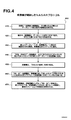
図4は、本発明の原理に基づいて、受信機が開始したノーマルSRA(NASAR)通信によるビットレート変更の処理の実施形態を表すフローチャート400を示している。図4において、実行ボックス410から470中に説明されているステップは、前述の説明に対応している。
【0081】
送信機が開始したNASARプロトコル
送信機が開始したNSRAは、以下のステップを含んでいる:
1. 初期化の間、送信機と受信機は、データレートに関する最大および最小能力を示す情報を交換する。これは、DMTシンボル毎のビット数の最小値及び最大値と対応する。
【0082】
2. 送信機は、データレートを早くするべきか、それとも遅くするべきかを決定する。
【0083】
3. 所望のデータレートが受信機のレート能力の範囲内である場合、送信機はステップ4に進む。
【0084】
4. 送信機は、EOC又はEOCチャネルを用いて新しい所望のデータレートを受信機に送る。これが”NSAR Request(NSAR要求)”メッセージである。
【0085】
5. 受信機は、そのNSAR要求メッセージを受信する。チャネルが新しいデータレートを支えることができるのであれば、受信機はステップ6に進む。チャネルが新しいデータレートを支えることができるないのであれば、受信機は、EOC又はEOCチャネルを用いて”SRA Deny (SRA を拒絶)”メッセージを送信機に返送する。
【0086】
6. 受信機は、新たなビットレートに基づき、EOC又はEOCチャネルを用いて新しいBATを送信機に送る。これは、受信機による”NSRA Grant(NSRA 許可)”要求に対応する。
【0087】
7. 送信機は、”NSRA Grant”要求を受信する。
【0088】
8. 送信機は、受信機に対して新しいBATが用いられることを知らせるフラグとして反転同期シンボルを用いる。新しいテーブルは、反転同期シンボルの一定フレーム数後に、最初のフレーム上で送信用に用いられる。この反転同期シンボルは、送信機によって送られたレート適合メッセージ”SRA Go”として動作する。
【0089】
9. 受信機は、反転同期シンボル(”SRA Go”)を検出し、新しいテーブルは、反転同期シンボルの一定フレーム数後に、最初のフレーム上で受信用に使用される。
【0090】
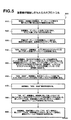
図5は、本発明の原理に基づいて、送信機が開始したノーマルSRA(NASAR)通信によるビットレート変更の処理の実施形態を表すフローチャート500を示している。図5において、実行ボックス510から590中に説明されているステップは、前述の説明に対応している。
【0091】
レート適合は、BATを変更することにより、DMTシンボル内のビット数を変更するだけでよく、R−Sコードワードサイズ、インターリーバー深さ、又はADSLフレームサイズを変更する必要はない。かかる変更は、データフローの中断又はデータエラーを引き起こすことなく、実行することができる。
【0092】
本発明のこのプロトコルは、送信機と受信機との間で、新しい通信パラメーター及びレートの承認をするための長時間のハンドシェイクが必要ないので、従来のレート適合方法よりも高速である。データレート能力があらかじめ知られ、設定中に処理されるので、長時間のハンドシェイクは不要である。また、他のパラメーター(R−Sコードワード長さ、インターリーバー深さ等の)は、新しいフレーミング法を用いたデータレートの変更の間、変化しない。
【0093】
本発明のこのプロトコルは、新しいデータレートへの移行を同期させるため”SRA Go”のメッセージを送るのにEOC又はAOCチャネルを用いないので、従来のレート適合技術よりも丈夫である。従来のレート適合技術において、EOC又はAOCチャネルを介して送られたメッセージは、ラインのノイズによって簡単に破壊されてしまう。これらのオーバーヘッドチャネルは、フレーマーにおいてデータストリームに多重化され、直交振幅変調(quadrature amplitude modulation)によって定められた数のDMTサブチャネル上に送信される。ラインで生じるパルスノイズ又は他のノイズは、AOCチャネルメッセージで容易にビットエラーを引き起し、かかるメッセージが失われるおそれがある。”SRA Go”メッセージが破壊され、受信機で受信されない場合、受信機はSRA要求が許可されたかどうかが判らない。他方、送信機は、”SRA Go”メッセージが受信されたと推測し、新たなデータレートおよび送信パラメーターへの切り換えをおこなう。許可メッセージを受信していない受信機は、いつ新しいレートに切り換えたらよいのか判らない。こうして、モデムは同期せず、データエラーが生じる。
【0094】
本発明のプロトコルは、従来のレート適合技術と違い、破壊されやすいEOC又はAOCメッセージを介して”SRA Go”メッセージを送らないので、丈夫である。
【0095】
そうではなく、レート適合要求を反転同期シンボルを介してやりとりされる。同期信号は、69シンボル毎に送信される固定のデータを搬送しない(non-data carrying)DMTシンボルとしてANSIおよびITU規格で規定されている。
【0096】
この同期信号は、基本的なAQPSK(2ビットのQAM)変調を用いて所定のPNシーケンスを有する全てのDMTキャリアを変調することにより構成されている。モデムの初期化プロセスを通じて用いられているこの信号は、非常にノイズの多い環境下であっても同期信号および反転同期信号の検出を可能にする特殊な自己相関特性(special autocorrection properties)を有する。反転同期信号は、QAM信号の位相情報が180度変位された同期信号である。SRAに進むメッセージ用には、他の位相変位(180度以外)の同期信号も用いることができる。かかる同期信号を”SRA Go”メッセージ用に用いることで、ノイズの激しい環境においてもレート適合プロトコルを耐性のあるものにする。
【0097】
記憶したBATsを用いる高速SRA(FSRA)プロトコル
高速SRA(FSRA)プロトコルは、NSRAプロトコルよりも高速にライン上のデータレートをとぎれなく変更する。このことは、起動・停止が瞬間的に行われたり、突然チャネルの変更が行われる特定のアプリケーションにとって重要なことである。FSRAプロトコルにおいて、”Stored BATs(記憶したBATs)”は、SRAハンドシェイク高速化のため、およびデータレートの迅速な切り換えを可能にするため用いられる。G992.2で用いられたプロファイルとは違い、記憶されたBATは、R−Sコーデイングおよびインタリービングパラメーターを含んでいない。これは、一定割合のオーバーヘッドフレーミングを用いるレートの変更が行われた場合にこれらのパラメーターが有効でなくなってしまうからである。
【0098】
BATsは、前のセクションで説明したNSRAを用いて交換される。ワンタイム(one time)NSRAが終了し、その特定のチャネル条件又はアプリーション条件に基づくBATがトランシーバーの両側に記憶されると、FSRAプロトコルは、オンラインで高速にレート適合を実行するため、記憶されたBATを用いることができる。記憶されたBATsは、送信機および受信機の双方が、実際に情報を再度送ることなしに、相手に対してどのテーブルが用いられるかを知らせるためだけにラベル付けされる。例えば、記憶されたBATsに番号を付してもよい。送信機又は受信機は、トランシーバーの相手側に対し、次の通信にどのBATテーブル番号が用いられるのかを知らせる必要がある。送信機又は受信機のいずれでもFSRAを開始することができる。
【0099】
受信機が開始したFSAR
受信機が開始したFSARは、以下のステップを含んでいる:
1. 受信機は、データレートを早くするべきか、それとも遅くするべきかを決定する。
【0100】
2. 記憶されたBATが新しいチャネルおよび/又はアプリケーション条件に合致していれば、受信機は、ステップ3に進む。条件に合致する記憶BATがない場合、NSRAが開始される(上述のように)。
【0101】
3.受信機は、送信機に対し、新しいチャネルおよび/又はアプリケーション条件に基づき、通信用にどの記憶BATが用いられるのか特定するためのメッセージを送る。これは、受信機による”FSRA Request(FSRA 要求)”に対応する。
【0102】
4. 送信機は、”FSRA 要求”を受けとる。
【0103】
5. 送信機は、受信機に対し、送信用に要求された記憶BATが用いられることを知らせるフラグとして反転同期シンボルを用いる。当該記憶BATは、反転同期シンボルの一定フレーム数後に、最初のフレーム上で送信用に使用される。この反転同期シンボルは、送信機によって送られたレート適合メッセージ”SRA Go”に相当する。
【0104】
6. 受信機は、反転同期シンボル(”SRA Go”)を検出し、新たなBATは、反転同期シンボルの一定フレーム数後に、最初のフレーム上で受信用に使用される。
【0105】
図6は、本発明の原理に基づいて、送信機が開始した高速SRA(FASAR)通信によるビットレート変更の処理の実施形態を表すフローチャート600を示している。図6において、実行ボックス610から660中に説明されているステップは、前述の説明に対応している。
【0106】
送信機が開始したFSAR
送信機が開始したFSARは、以下のステップを含んでいる:
1. 送信機は、データレートを早くするべきか、それとも遅くするべきかを決定する。
【0107】
2. 記憶されたBATが新しいチャネルおよび/又はアプリケーション条件に合致していれば、送信機は、ステップ3に進む。条件に合致する記憶BATがない場合、NSRAが開始される(上述のように)。
【0108】
3. 送信機は、受信機に対し、新しい新しいチャネルおよび/又はアプリケーション条件に基づき、通信用にどの記憶BATが用いられるのか特定するためのメッセージを送る。これは、送信機による”FSRA 要求”に対応する。
【0109】
4. 受信機は、”FSRA 要求”を受けとる。
【0110】
5. 受信機は、”FSRA 要求”に許可を与えるため、送信機に対して”FSRA Grant”メッセージを返送する
6. 送信機は、”FSRA Grant”を受けとる。
【0111】
7. 送信機は、受信機に対し、送信用に要求された記憶BATが用いられることを知らせるフラグとして反転同期シンボルを用いる。特定されたBATは、反転同期シンボルの一定フレーム数後に、最初のフレーム上で送信用に使用される。この反転同期シンボルは、送信機によって送られたレート適合メッセージ”SRA Go”に相当する。
【0112】
8. 受信機は、反転同期シンボル(”SRA Go”)を検出し、新たなBATは、反転同期シンボルの一定フレーム数後に、最初のフレーム上で受信用に使用される。
【0113】
図7は、本発明の原理に基づいて、送信機が開始した高速SRA(FASAR)通信によるビットレート変更の処理の実施形態を表すフローチャート700を示している。図7において、実行ボックス710から780中に説明されているステップは、前述の説明に対応している。
【0114】
FASARプロトコルは、非常に高速で実行することができる。かかるプロトコルは、二つのメッセージ(FSRA許可およびFSRA要求)と反転同期シンボルの交換だけを必要とする。BATが記憶されており、交換する必要がないので、FSRAは、NSRAよりも高速である。FSRAプロトコルは、NSRAプロトコルのように、”SRA Go”用に反転同期信号を用いているので、雑音の多い環境においても丈夫である。
【0115】
SRAプロトコルをパワーの管理(低パワーモードへの出入り)に使用する
フルパワーモードは、トランシーバーの通常の動作中に用いられる。低パワー通信モードは、ライン上にデータを送信する必要がない場合に、トランシーバーの電力を節約するために用いられる。多くのモデムが、通信の要求が少ない場合にトランシーバーを非常に低いパワーレベルで動作させるための低パワーモード又は”スリープモード”を有している。また、多くのモデムは、それらが高速で低パワーモードに出入りすることを可能にするプロトコルを有しているので、モデムが低パワーモードへ移行することでユーザーに不便をかけることはない。本発明により提供されるSRAプロトコルは、高速、かつ、とぎれなく低パワーモードに出入りするために用いられる。
【0116】
低パワーモード(LPM)には、二つの基本的なタイプがある:
低データレートLPM
これは、非常に低いデータレートを有する低パワーモードである(例えば、32kbps)。サブチャネルのいくつかが使用されているにすぎない。ループのタイミングを維持するために、パイロット・トーンを発信してもよい。
【0117】
ゼロデータレートLPM
この低パワーモードは、実質的に0kbpsのデータレートを有する、すなわち、どのサブチャネルもデータを変調していない。データ接続も維持されていない。この場合にも、ループのタイミングを維持するために、パイロット・トーンを発信してもよい。
【0118】
低データレートLPMおよびゼロデータレートLPMの双方において、通常のフルパワーモードにおいて69シンボル毎に送られる同期シンボルは、オン又はオフでもよい。低パワーモード中にも同期シンボルが送られている場合、受信機は、その同期シンボルを、チャネル変更およびライン上の他の変動を監視するために用いることができる。しかし、同期シンボルを69シンボル毎に送ると、非定常的な混信(non-stationary crosstalk)を起こし、同じ電話線上又は同じワイヤ束中の他の信号に有害となり得る。低パワーモード中に同期シンボルが送られていなければ、電話線上又はワイヤ束に定常的な混信は発生しない。しかし、この場合、同期シグナルによってチャネルを監視することができなくなる。
【0119】
FRSAを用いて低パワーモードに入る
1. 受信機が開始した低パワーモードへの移行
受信機は、受信機が開始したFSRAプロトコルを用いて低パワーモ−ドへの移行を開始する。低パワーモ−ドへの移行を開始した受信機は、当該低パワーモ−ドに対応する記憶BATを用いる。当該低パワーモ−ド用の記憶BATテーブルは、低データレートLPM又はゼロデータレートLPMのいずれかをイネーブルにする。この低パワーモ−ド用BATは、システムによってあらかじめ定義することもでき、または、NSRAプロセスを用いて置換し、記憶させるようにしてもよい。いずれの場合でも、受信機は、低パワーモードBATを指定し、通信用の当該BATの使用に同期的に切り換えるため、受信機が開始したFSRAプロトコルを用いる。
【0120】
2. 送信機が開始した低パワーモードへの移行
送信機が開始したFSRAプロトコルを用いて低パワーモ−ドへ移行するには、二つの方法がある。一つの実施形態としては、送信機が送信機が開始したFSRAプロセス全体を用いるとともに、移行を要求する。受信機が開始した低パワーモードへの移行の場合のように、低パワーモードへ移行する送信機は、当該低パワーモード用の記憶BATを用いる。当該低パワーモード用の記憶BATテーブルは、低データレートLPM又はゼロデータレートLPMのいずれでもイネーブルすることができる。この低パワーモ−ド用BATは、システムによってあらかじめ定義することもでき、または、NSRAプロセスを用いて交換し、記憶させるようにもできる。いずれの場合でも、送信機は、低パワーモードBATを指定し、通信用として同時に当該BATへ切り換えるため、送信機が開始したFSRAプロトコルを用いる。
【0121】
第二の実施形態としては、送信機が、上述の送信機が開始したFSRAプロトコルのステップ7に直接移行し、低パワーモードへの移行を示す反転同期シンボルを送信する方法がある。受信機は、反転同期を検出し、低パワーモードへ移行する。この場合、FRSA要求が送信機によって送信されていないので、受信機は、FSRA要求なしで受信した同期シンボルが、送信機が低パワーモードに移行しつつあることを示すものとして認識する。送信機および受信機の双方がBATを用いるよう、低パワーモードBATが(システムにより予め定義され)、又は識別されて、予め記憶される。第二の実施形態において、ステップ7では、送信機は、送信機と受信機によってFSRAなしに低パワーモ−ドへ移行するために使用される信号であると予め定義されている信号とは別の信号を送信する。例えば、送信機は、反転(180度)した同期シンボルでなく、位相が45度回転した同期シンボルを送信してもよい。位相を45度回転させた同期シンボルは、送信機が、反転シンボルの45度回転後一定フレーム数後に、最初のフレーム上で当該低パワーモードに対応する記憶BATを用いて低パワーモードに移行しつつあることを示す。
第二の実施形態において説明した送信機が開始した低パワーモードへの移行は、移行のために反転チャネルを作る必要がないという利点を有する。反転チャネルは、反対方向の通信チャネルとして定義される、すなわち、ここでは、受信機から送信機にFRSAメッセージを送るのに用いられる通信チャネルがこれにあたる。反転チャネルは、データ接続なしでも既に低パワーモードなので好都合である。送信データの準備が整っていない場合、送信機は、単に低パワーモ−ドに移行すればよい。ラインを介して信号を送信するのに必要となるために送信機が電力の大部分を消費するので、このことは重要なパワー節約技術である。送信機が開始した低パワーモードへの移行は、”ソフトモデム(soft modem)”(PCホストベース)を実行する場合にも、有用である。ソフトモデムを実行する場合、ホストプロセッサーは、モデムトランシーバー機能および他の多くのPCアプリケーションを同時に実行する。ホストプロセッサーが、ADSL送信機の動作を許容しない他のタスクを実行しなければならない場合、当該プロセサーは、反転同期シンボル又は45度回転させた同期シンボルを送信することにより送信機を速やかに低パワーレートに移行させる。この後、前記他のタスクによりホストプロセッサー資源が使用可能となる。ADSL送信機は、信号をラインに送り出さない(0kbps)。
【0122】
上記で説明した送信機および受信機が開始したプロトコルは、通信システムが各方向(上流方向および下流方向)別々に又は両方向一緒に、低パワーモードに入ることを可能とする。上述の場合は、一方向の場合について説明していた。このプトロコルは、両方向への移行を同時に達成できるよう組み合わせることもできる。例えば、顧客構内トランシーバー(customer premise transceiver)(CPT)は、PCが低パワーモードになるとCPTもそうなるように設計されている。このCPTは、下流方向(電話局(CO)からCPTへの方向)を低パワーモードにするため、最初に受信機が開始した低パワーモードへの移行を用いる。次に、CPTは、上流方向(CPTから電話局(CO)への方向)を低パワーモードにするため、送信機が開始した低パワーモードへの移行を用いる。
【0123】
低パワーモードからの脱出
1. 受信機が開始した低パワーモードからの脱出
SRAプロトコルによれば、低パワーモ−ドから脱するために受信機が用いることのできるものには、二つの実施形態がある。一つ目の実施形態において、低パワーモードが逆方向において少なくともゆっくりしたデータ接続を未だに有している(低データレートのLPMの)場合、受信機が開始した低パワーモードからの脱出は、受信機が開始したNSRA又はFSRAプロトコルを用いて実行することができる。受信機は、用いられるBATとともにSRA要求を送信機に返送可能でなければならないので、このことが必要となる。送信機が低パワーモードにおいて同期シンボルをオフにしなかった場合、上述のように、NSRA又はFSRAプロトコルが用いられる。送信機が低パワーモード中に同期シンボルをオフにすると、同期シンボルをオンに戻すことにより送信機によって”SRA Go”が送信される。受信機は、データレートの変更を同期させるためのフラグとして同期シンボルの存在(反転を伴うか、伴わないか)を検出する。
【0124】
第二の実施形態において、逆方向ではデータ接続がない(ゼロデータレート LPM)。受信機は、最初に、逆方向において”送信機が開始した低パワーモ−ドからの脱出”(以下で説明するを実行することにより脱出)をはじめる。これにより、逆方向でのデータ接続が可能となる。受信機は、低パワーモードから自身の方向へと脱するために、受信機が開始したNSPA又はFSRAプロトコルを用いる。上述のように、送信機が低パワーモード中に同期シンボルをオフにすると、同期シンボルをオンに戻すことにより送信機によって”SRA Go”が送信される。受信機は、データレートの変更を同期させるためのフラグとして同期シンボルの存在(反転を伴うか、伴わないか)を検出する。
【0125】
2.送信機が開始した低パワーモードからの脱出
SRAプロトコルによれば、低パワーモ−ドから脱するために送信機が用いることのできるものには、二つの実施形態がある。一つめの実施形態において、送信機は、送信機が開始したFSRA又はNSRAプロセス全体を用いるとともに、移行を要求する。これにより、両方向においてデータ接続(低データレートのLPM)が必要となり、プロトコルメッセージが交換可能となる。受信機が開始した低パワーモードからの脱出のように、送信機が低パワーモードにおいて同期シンボルをオフにしなかった場合、上述のように、NSRA又はFSRAプロトコルが用いられる。送信機が低パワーモード中に同期シンボルをオフにすると、同期シンボルをオンに戻すことにより、送信機によって”SRA Go”が送信される。受信機は、データレートの変更を同期させるためのフラグとして同期シンボルの存在(反転を伴うか、伴わないか)を検出する。
【0126】
第二の実施形態において、送信機は、送信機が開始したFSRAプロトコルのステップ7に直接移行することにより、低パワーモ−ドから脱することができる。送信機は、低パワーモ−ドから脱したことを示すために反転同期シンボルを送る。これには、低パワーモ−ド中に同期シンボルを送ることが必要となる。このプロトコルは、低データレートLPMを必要としない。受信機は、反転同期シンボルを検出して、低パワーモードを脱する。受信機は、FSRA要求なしで受信した反転同期シンボルが、送信機が低パワーモ−ドから脱したことを示すことを認識するよう構成されている。フルパワーモードのBATは、接続内で送信機と受信機のいずれもがBATをもつように、前もって識別され、記憶されている。例えば、低パワーモードからの脱出時に使用されるBATは、最後フルパワー接続(last full power connection)BATに初期設定されるようシステムによって定義される。これに代えて、送信機は、送信機と受信機によってFSRAなしに低パワーモ−ドへ移行するために使用される信号であると予め定義されている信号とは別の信号を送信する。送信機は、反転(180度)した同期シンボルでなく、位相が45度回転した同期シンボルを送信してもよい。受信機が、同期シンボルの位相が45度回転していることを検出すると、受信機は、反転シンボルの45度回転後一定フレーム数後に、最初のフレーム上でフルパワーモードに対応する記憶BATを用いて送信機が低パワーモードから移行しつつあることを検出する。送信機が低パワーモード中に同期シンボルをオフにすると、同期シンボルをオンに戻すことにより送信機によって”SRA Go”が送信される。受信機は、データレートの変更を同期させるためのフラグとして同期シンボルの存在(反転を伴うか、伴わないか)を検出する。
【0127】
BATは、本説明を通じて、各サブチャネルに割り当てられたビットの数を特定するためのテーブルとして定義されているが、BATは、マルチキャリアシステムのサブチャネルにビット割り当てに関連する他のパラメーターを含んでいてもよい。追加パラメーターの例としては、ANSIおよびITU規格に定義されているサブチャネル毎のファインゲイン(Fine Gain)がある。この場合、BATがNSRAプロトコル中で交換されるか、FSRAプロトコル中に保存される場合、BATは、また、各サブチャネル毎にファインゲイン値を有する。
【0128】
シームレスレート適合システムおよび関連するプロトコルが、二重(又は複数)遅延パスを実現するDMTシステムに適用される。二重遅延システムは、ITUおよびANSI規格に、フレーマー/FECブロックにおいて異なる仕様を有する二つのデータストリームを指示するDMTシステムとして規定されている。図3は、複数の遅延を有するシステムの一例として二重遅延パスを実現する標準的なADSL DMTシステム300を示している。システム300は上述の図1で説明されている三つのレイヤと似てはいるが、同じでない、変調レイヤ310,フレーマーFECレイヤ320、およびATM TCレイヤ340の:3つのレイヤを含んでいる。
【0129】
変調レイヤ310は、DMT変調に関連する機能を提供する。このDMT変調は、反転デイスクリートフリエ変換器(Inverse Dsicrete Fourier Transform)(IDFT)112を用いて実行される。このIDFT112は、直交振幅変調(Quadrature Amplitude Modulation)エンコーダ314からのビットをマルチキャリアサブチャネル内に変調する。変調レイヤ310の機能は、図1の変調レイヤ110と似ているが、変調レイヤ310が複数入力を有するのに対し、単一の入力しかないという点で相違している。
【0130】
図3に示すフレーマー/FECレイヤ320は、二つのパスを有している。このレイヤは、図1のフレーマー/FECレイヤ120に示すものと同じブロック、すなわち、インターリービング(INT)ブロック122,フォワードエラー訂正(FEC)ブロック124、スクランバー(SCR)ブロック126、サイクリック・リダンダンシー・チェック(CRC)ブロック128およびADSLフレーマーブロック130を含んでいる。さらに、このレイヤは、第二のフォワードエラー訂正(FEC)ブロック124’、スクランバー(SCR)ブロック126’、サイクリック・リダンダンシー・チェック(CRC)ブロック128’およびADSLフレーマーブロック130’のそれぞれを含む第二パスを備えている。フレーマー/FECレイヤ320は、変調用のビットストリームの準備と関連する機能を提供する。
【0131】
下方のパスは、データストリームのインターリービングを行わないので、レーマー/FECレイヤ320を通過する新しい下方のパスは、図1のそれに相当する元々ある上方のパスとは違った遅延値を有する。異なる遅延要件を有する異なるアプリケーションビットストリームをADSL DMTモデムを介して送るために二重遅延が用いられる。例えば、遅延が大きくてもよいアプリケーション(例えば、ビデオオンデマンド)の場合、上方の遅延の大きいパスを介してインターリービングを伴う送信をしてもよいが、遅延が小さいことが要求されるアプリケーション(例えば、音声)の場合、下方の遅延の小さいパスを介しインターリービングを行わないで送信すべきである。
【0132】
ATM TCレイヤ340は、セル内のビットおよびバイトをそれぞれのパス用にフレームに変換する複数の入出力端を有するATM TCブロック342を備えている。
【0133】
本発明のシームレスレート適合システムおよび方法は、二重遅延、又は、複数遅延を有するシステムであっても適用される。二重遅延の場合、両方のパスのためのFECおよびインターリービングパラメーターは、DMTシンボルサイズとは関係がない。BATは、各サブチャネルに割り当てられるビット数とは別に各遅延パス用のデータレートを含んでいる。FSRAおよびNSRAプロトコルを用いてシームレスレート適合がなされた場合、BATは、各遅延パス用のデータレートをも示す。例えば、二重遅延システムが、インターリーブパス(遅延の大きい上方のパス)上で1.536Mbpsで、インターリーブがなされないパス(遅延の小さい下方のパス)上で256kbpsで作動しており、SRAが開始されている場合、SRAプロトコルは、サブチャネル毎のビット数および各遅延パス毎の新しいデータレートを含む新たなBATを特定する。DMTシンボルレートが4kHZの場合、システムは1.536Mbps+256kbps=1.792Mpsで動作し、シンボル毎の総ビット数は、1792000/4000=448個となる。BATは、シンボルごとに1536000/4000=386ビットが、インターリーブパスに割り当てられ、256000/4000=64ビットが、非インターリーブパスに割り当てられるということを示す。例えば、SRAが実行されると、インターリーブパスの新たなデータレートを、1.048Mbps(1048000/4000=シンボル毎に262ビット)、非インターリーブパスの新しいデータレートを、128kbps(128000/4000=DMTシンボル毎に32ビット)とすることができる、これにより、総スループットレートを1.176kbps(又はDMTシンボルごとの総ビット数を294個)にすることが可能となる。本明細書内で説明したフレーミング方法と組み合わされたNSRAおよびFSRAプロトコルは、このようなデータレート変更を両方の遅延パスでとぎれなく行うことができる。また、両方のパスのデータレートを変更しないようにすることもできる。例えば、256kbpsの遅延の小さいパスは、低いレートでは動作できない音声データ(複数の通話)を搬送しているで、データレートを一定に維持しておくことが好ましいが、1.536Mbpsのパスは、低いデータレートでも動作することのできるインターネットアクセスデータを搬送することができる。
【0134】
この例では、SRA中、遅延の小さいパスのデータレートが256kbpsに維持されるが、遅延の大きいパスのデータレートは変更される。
【0135】
ADSLシステムと関連させて本発明を開示したが、マルチキャリア変調を用いるシステムであれば、どのようなものにも適用できる。
【0136】
特定の好ましい実施形態を参照しながら本発明を開示し、説明したが、当業者であれば、添付クレームによって定められた本発明の精神および範囲から外れることなく、形態および細部に関して様々な変更をなす事ができるということを理解すべきである。
【図面の簡単な説明】
本発明の目的及び特徴は、以下に説明する図面を参照すれば、より明確に理解することができる。図面は、本発明の原理を表すために、その縮尺を変えたり、強調したりする必要はない。
【図1】 図1は、基準に準拠している既知のADSL DMT 送信機のブロック図である。
【図2】 図2は、ADSL フレームおよびR-Sコードワードの代表的な実施形態である。
【図3】 図3は、二重遅延ADSL DMT 送信機のブロック図である
【図4】 図4は、本発明の原理に基づき、ノーマルシームレスレート適合(NSRA)通信ビットレート変更を受信機が開始する場合の処理プロセスの一実施形態を示すフローチャートである。
【図5】 図5は、本発明の原理に基づき、ノーマルシームレスレート適合(NSRA)通信ビットレート変更を送信機が開始する場合の処理プロセスの一実施形態を示すフローチャートである。
【図6】 図6は、本発明の原理に基づき、高速シームレスレート適合(FSRA)通信ビットレート変更を受信機が開始する場合の処理プロセスの一実施形態を示すフローチャートである。
【図7】 図7は、本発明の原理に基づき、高速シームレスレート適合(FSRA)通信ビットレート変更を送信機が開始する場合の処理プロセスの一実施形態を示すフローチャートである。[0001]
[Display related applications]
This specification is a co-pending provisional application and is consistently compatible with US Provisional Patent Application No. 60 / 124,222, filed March 12, 1999, which is incorporated by reference in its entirety. (SRA) ADSL System ", US Provisional Patent Application No. 60/161/115 filed Oct. 22, 1999, title of invention" Multi-Carrier System with Application History Stored ", and Jan. 19, 2000 Claims priority from US Provisional Patent Application No. 60 / 171,081, entitled “Ratelessly Adapting Rates (SRA) Multicarrier Modulation Systems and Protocols”.
[0002]
FIELD OF THE INVENTION
The present invention relates to a communication system and method using multicarrier modulation, and more particularly, to a communication multicarrier system and method using rate adaptive multicarrier modulation.
[0003]
BACKGROUND OF THE INVENTION
Multi-carrier modulation (or discrete multi-tone modulation) is a communication method that is widely used for communication via a medium that is difficult to communicate. Multi-carrier modulation divides a communication frequency band into a plurality of subchannels (carriers) in which each carrier independently modulates a bit or a set of bits. The transmitter modulates an input data sequence including information bits with one or more carriers, and transmits the modulated information. The receiver demodulates all carriers to recover the transmitted information bits as an output data stream.
[0004]
Multi-carrier modulation has many advantages over a single carrier. These benefits include, for example, high immunity to impulse noise, no complexity in the presence of multipath, high immunity to narrowband interference, and high data rate and bandwidth flexibility. . Multi-carrier modulation is used in many applications not only for these benefits, but also for other reasons. Such applications also include asymmetric digital subscriber line (ADSL) systems, wireless LAN systems, power line communications systems, and other applications. ITU standard G992.2 and ANSI standard T1.413 specify standard implementation requirements for ADSL transceivers using multi-carrier modulation.
[0005]
FIG. 1 is a block diagram showing an ADSL DMT transmitter 100 conforming to a conventionally known standard. FIG. 1 shows three layers:
[0006]
The
[0007]
A table that defines how many bits are allocated to each subchannel for modulation in one DMT symbol is called a bit allocation table (BAT). The DMT symbol is a collection of analog sample signals generated on the output side of the IDFT by modulating the carrier with bits based on the BAT. The BAT is a main parameter used also in the
[0008]
[Table 1]
Since many bits are modulated on each DMT carrier, the bit rate is high. If the channel conditions are not good, the signal-to-noise ratio is low, and the number of bits modulated on each DMT carrier is reduced, resulting in a lower system bit rate. As seen in Table 1, the modulation bit is zero for some subchannels. One example is a case where a narrowband interference signal (such as an AM broadcast radio wave) exists in the frequency of the subchannel, and the information bit cannot be transmitted because the SN ratio is too low in the subchannel.
[0009]
The
[0010]
The next layer of the ADSL system is a frame /
The main parameters in the frame /
[Formula 1]
N FEC = SxN BAT Where S is a positive integer and is greater than zero.
[0011]
Such a restriction can also be expressed as one RS codeword containing an integer value of a DMT symbol. The RS code word includes a data byte and a parity (check byte). The check byte is an overhead byte added by the RS encoder and is used by the RS decoder for bit error detection and correction. There are R check bytes in the RS codeword. Usually, the number of chuck bytes only accounts for a small percentage of the total codeword size, for example 8%. Most channel coding methods are characterized by their coding gain, defined as the improvement in system performance (denoted in dB) given by the code, compared to an uncoded system. The coding gain of the RS code word is determined by the number of check bytes and the size of the RS code word. A large R-S codeword with 16 check bytes (8% of 200 bytes) (greater than 200 bytes in a DMT ADSL system) yields 4 dB close to the maximum coding gain. If the codeword size is small and / or the percentage of check byte overhead is large (eg, over 30%), the coding gain will be very small or negative. Typically, ADSL systems are best to run RS codewords as large as possible (maximum possible value is 255 bytes) and operate at about 8% redundancy.
[0012]
N which is an ADSL frame FRAME And N is the size of the RS codeword FEC Is the specific relationship shown in equation (2):
[Formula 2]
N FEC = SXN FRAME Where R is the number of check bytes in the codeword and S is a positive integer the same as in equation (1).
[0013]
It is clear that equation (3) is derived by equating the right side of equations (1) and (2) with equals;
[Formula 3]
N BAT = N FRAME + R / S.
[0014]
The ADSL standard requires an integer value rate (R / S), ie DMT-symbol (N BAT ) Request an integer R-S check byte. As described above, the ADSL frame includes overhead bytes (not as part of the payload) used for communication between modems. Since the bytes in the ADSL frame used for the overhead channel cannot be used for actual communication by the user, the user data rate is reduced accordingly. The content of the information and the format of these channels are described in the ITU and ANSI standards. Several framing modes are defined in the ADSL standard. Depending on the framing mode, the overhead bytes in one ADSL frame may be more or less. For example, standard framing mode 3 has one overhead for each ADSL frame.
[0015]
Equations (1), (2), and (3) show that the following conditions are required due to parameter restrictions imposed by the standard.
[0016]
1. Every DMT symbol has a fixed number of overhead framing bytes added in the ADSL framer. For example, in framing mode # 3, there is one overhead framing byte for each DMT symbol.
[0017]
2. There is at least one R-S check byte for each DMT symbol.
[0018]
3. ITU standard G. 992.2 (8) and ITU standard G.264. 992.2 and T1413 (16), the maximum number of check bytes is the maximum value of the codeword size. 8xN for 992.2 BAT G. 16xN for 992.1 BAT Limited to
[0019]
4). The ADSL modem uses the RS codeword (N FEC ) And ADSL frames (N FRAME ) Without changing the number of bytes appropriately. BAT ) Cannot change the number of bits.
[0020]
Due to the above four limitations, existing ADSLs are limited in performance.
[0021]
In particular, according to condition # 1, each DMT symbol has a fixed number of overhead framing bytes. Such a condition is problematic when the data rate is low and overhead framing bytes occupy a large percentage of the available throughput, resulting in a small payload. For example, if the data rate obtained by the line is 6.144 Mbps, this is approximately 192 bytes per symbol (192 × 8 × 4000 = 614400 bps) for DMT symbols. In this case, one overhead framing byte occupies 1/192 or about 0.5% of the available throughput. However, if the data rate is 128 kbps or 4 kbps per symbol, overhead framing bytes will occupy a quarter or 25% of the available throughput. This is clearly undesirable.
[0022]
Condition # 2 causes the same problem as condition # 1. In this case, the RS check byte is exchanged for the overhead framing byte.
[0023]
If the data rate is low due to condition # 3, a large codeword configuration cannot be adopted. An RS codeword in ADSL can have a maximum of 255 bits. The code gain is near the maximum 255 bits situational The maximum value is obtained. When the data rate is low, ie, 128 kbps or 4 bytes, the maximum codeword size is G. 8x4 = 32 bytes for G.992.2 systems, G. For 992.1 and T1.413 systems, 16x4 = 64. In this case, the code gain is substantially lower than that where the code word approaches 255 bytes.
[0024]
Typically, if the data rate is low, for example 128 kbps or 4 bytes per symbol, 1 byte is used for overhead framing and 1 byte is occupied by the RS check byte according to the above conditions. Therefore, 50% of the available throughput is not used for the payload and the size of the RS codeword is up to 64 bytes, which results in almost no code gain.
[0025]
Condition # 4 affects the modem's ability to adapt its communication parameters online in a dynamic manner.
[0026]
G. 992.1 and T1.413 specify an online rate adaptation mechanism called Dynamic Rate Adaptation (DRA), but these standards specify that data rate changes are not seamless. Yes. Existing ADSL DMT modems typically use bit swapping and dynamic rate adaptation (DRA) as methods of online adaptation to channel changes. Bit swapping is defined in the ITU and ANSI standards as a way to modify the number of bits assigned to a specific target. Bit swapping is uninterrupted, that is, this method does not interrupt data transmission / reception. But, Some bit swapping The data rate cannot be changed. Bit swapping can only change the number of bits allocated to a carrier while keeping the data rate the same. This means that the total number of bits in the BAT (N BAT ) Is the same as changing the input item of the BAT table without increasing or decreasing.
[0027]
DRA allows for changing the data rate, but it is not performed continuously. Also, DRA is very slow because it needs to install a modem in the central office (CO) to make a final decision regarding the data rate. This method (CO becomes the master) is common in ADSL modems that are configured to be serviced and managed by a telephone company.
[0028]
Both bit-swapping and DRA are ANSI T1.413 and G992.1 and G.264. Use a specific protocol to handle the changes specified in 992.2. This protocol processes the parameters using messages sent over an AOC channel that is an embedded channel. This protocol is vulnerable to pulses and high noise levels. If the message breaks, the transmitter and receiver will be in a situation using different parameters (ie, BAT, data rate, RS codeword length, interleaver depth, etc.). If the two communication modems get into a situation that causes a mismatch in the communication parameters, the data will receive an error signal and the modem will eventually end up (such as completely reinitializing, etc.) to return to communication without recovery errors. ) It is required to take drastic measures. If a drastic measure such as complete re-initialization is taken, the service will be interrupted for about 10 seconds, which is the time required for the re-initialization of a standard-compliant ADSL modem.
[0029]
The transceiver has both a transmitter and a receiver. The receiver has the same blocks as the transmitter shown in FIG. The receiver has a module including a decoder, a deinterleaver and a demodulator. In operation, the receiver receives analog data transmitted from the transmitter, amplifies such signals with an amplifier as necessary, removes noise components, filters the signals for separation, and analog / digital The analog signal is converted to a digital signal using a converter, and the demodulator is used to demodulate the signal to extract the received bit stream from the carrier subchannel, and the de-interleaver is used to demodulate the bit stream. In order to interleave and correct errors, FEC decoding is performed using an FEC decoder, the descrambler is used to unscramble the bitstream, and CRC is also used to detect bit errors in the bitstream. Various semiconductor chip manufacturers supply hardware and software that perform the functions of a transmitter and / or a receiver.
[0030]
Thus, it is clear that there is a need to improve the DMT communication system. Accordingly, it is a primary object of the present invention to provide an improved DMT communication system that overcomes the aforementioned problems.
[0031]
Summary of the Invention
The principles of the present invention provide an ADSL DMT system and method that seamlessly changes the transmission bit rate during operation. The ADSL DMT system and method operates with a protocol that allows the transmission bit rate to be changed continuously during operations initiated by either the transmitter or the receiver. Also, the present ADSL DMT system and method can continuously change the transmission bit rate as the power level changes from full power to low power during operation.
[0032]
One aspect of the present invention relates to a method for seamlessly changing a transmission bit rate in a multi-carrier communication system. The method includes providing a plurality of codewords having a specific codeword size and including a specific number of parity bits for forward error correction. The method also includes providing an interleaving parameter for interleaving the plurality of codewords. The method further includes transmitting a first plurality of codewords at a first transmission bit rate, changing the first transmission bit rate to a second transmission bit rate, and a second plurality of codes. Transmitting a word at a second transmission bit rate, the specific interleave parameter used for the first plurality of codewords, the specific codeword size, and the specific number for forward error correction The parity bit is used for the second multiple codeword in order to change the transmission bit rate without interruption.
[0033]
In certain embodiments, transmitting at a first transmission bit rate includes assigning a first number of bits to a first DMT symbol as determined by a first bit assignment table. Transmitting at the second transmission bit rate includes allocating a second number of bits to the second DMT symbol as determined by the second bit allocation table. In other embodiments, the average parity bit rate for DMT symbols transmitted at the first and second transmission rates is substantially constant. The parity bit rate is the number of parity bits in a DMT symbol divided by the total number of bits in the bit allocation table used for that DMT symbol.
[0034]
Another aspect of the invention relates to another method for seamlessly changing a transmission bit rate in a multi-carrier communication system. The method includes providing a plurality of code words having a specific code word size, each code word including a specific number of parity bits for forward error correction. The method also includes assigning bits of a first plurality of codewords to a carrier subchannel using a first assignment table for transmitting a codeword at a first transmission bit rate; Transmitting a plurality of codewords at a first transmission bit rate. Further, the method assigns bits of a second multiple codeword to a carrier subchannel using a second assignment table for transmitting a codeword at a second transmission bit rate; and Changing the transmission from the first transmission bit rate to the second transmission bit rate by sending a codeword. The specific codeword size and the specific number of parity bits for forward error correction used when transmitting each of the first plurality of codewords change the transmission bit rate seamlessly. Used to transmit each of the multiple codewords.
[0035]
In another embodiment, the method comprises interleaving the first and second multiple codewords based on specific interleave parameters. The specific interleave parameter used to interleave the first multiple codewords is the same as the specific interleave parameter used to interleave the second multiple codewords. In another embodiment, the method further comprises interleaving the first and second multiple codewords based on specific interleave parameters. The specific interleave parameter used to interleave the first multiple codewords is the same as the specific interleave parameter used to interleave the second multiple codewords. In another embodiment, transmitting at the first transmission bit rate comprises assigning a first number of bits to a first DMT symbol as determined by a first bit assignment table. Transmitting at the second transmission bit rate includes allocating a second number of bits to a second DMT symbol as determined by a second bit allocation table. In another embodiment, the average value of the parity bit rate for DMT symbols transmitted at the first and second transmission rates is substantially constant.
[0036]
Another aspect of the present invention relates to another method for seamlessly changing a reception bit rate in a multi-carrier communication system. The method includes providing a plurality of codewords each having a specific number of parity bits for forward error correction and having a codeword size. The method also includes receiving a first plurality of codewords from a carrier subchannel at a first reception bit rate, and demodulating the bits of the first plurality of codewords using a first allocation table. Is included. The method further includes changing reception from the first received bit rate to the second received bit rate, receiving a second multiple codeword from the carrier subchannel at a second received bit rate, and And demodulating the bits of the second plurality of codewords using the second allocation table. The specific interleave parameter, the specific codeword size, and the specific number of parity bits for forward error correction used in demodulating each of the first plurality of codewords are uninterrupted in reception bit rate. In order to change, it is used when demodulating each of the second plurality of codewords. In some embodiments, the average parity bit rate for DMT symbols received at the first and second receive rates is substantially constant.
[0037]
In yet another aspect of the present invention, the present invention relates to another method for seamlessly changing a transmission bit rate in a multi-carrier system. The method includes providing a plurality of codewords having a specific codeword size and including a specific number of parity bits for forward error correction. The method also includes providing specific deinterleave parameters. The method further includes receiving a first plurality of codewords at a first reception bitrate, changing the first reception bitrate to a second reception bitrate, and changing the first plurality of codewords to the first reception. Receiving at two receiving bit rates. The specific interleave parameter, the specific codeword size, and the specific number of parity bits for forward error correction used for the first plurality of codewords change the reception bit rate seamlessly. Used for multiple codewords.
[0038]
In an embodiment, receiving at the first reception bit rate includes demodulating a first number of bits of a first DMT symbol as determined by a first bit allocation table. The step of receiving at the second reception bit rate includes the step of demodulating the second number of bits of the second DMT symbol as determined by the second bit allocation table. Furthermore, in another embodiment, the average value of the parity bit rate for DMT symbols received at the first and second reception rates is substantially constant.
[0039]
In still another aspect, the present invention relates to a multicarrier system that changes the transmission bit rate without interruption. Such multi-carrier systems include an encoder that produces a plurality of codewords having a specific codeword size and including a specific number of parity bits for forward error correction. The multicarrier system also includes an interleaver associated with the encoder, which interleaves the plurality of codewords based on specific interleave parameters. The multicarrier system further comprises a modulator associated with the interleaver. The modulator assigns each interleaved codeword to the carrier subchannel for transmission at the first transmission bit rate, and changes the bit assignment for transmission at the second transmission bit rate. The specific interleave parameter, the specific codeword size, and the specific number of parity bits for forward error correction are not changed even after the modulator has changed the bit allocation to transmit at a second transmission bit rate. Thus, the transmission bit rate can be changed without interruption.
[0040]
In one embodiment, the modulator transmits a first DMT symbol having a first number of bits determined by a first bit allocation table at a first transmission bit rate and a second bit allocation table. A second DMT symbol having a second number of bits determined by is transmitted at a second transmission bit rate. In another embodiment, the modulator transmits a first DMT symbol at a first transmission bit rate and a second DMT symbol at a second transmission bit rate. In this embodiment, the average value of the parity bit rate for the DMT symbols transmitted at the first and second transmission rates is substantially constant.
[0041]
In another aspect, the present invention relates to a receiver in a multicarrier communication system that continuously changes a reception bit rate. The receiver operates at a first received bit rate to produce a first plurality of interleaved codewords and changes operation to a second received bit rate to produce a second plurality of interleaved codewords. A demodulator is provided. Each codeword has a specific codeword size and includes a specific number of parity bits for error correction. The receiver also includes a deinterleaver associated with the demodulator that deinterleaves the first and second multiple interleaved codewords based on specific interleave parameters. Yes. In addition, such a receiver includes a decoder that cooperates with the demodulator to receive and decode the first and second multiple interleaved codewords. In order to seamlessly change the received bit rate, the specific interleaving parameter used for deinterleaving the first plurality of interleaved codewords is a specific interleaving used for deinterleaving the second plurality of interleaved codewords. The specific codeword size used for decoding the first multiple deinterleaved codeword and the specific number of parity bits for error correction are the same as the second multiple deinterleave It is the same as the specific codeword size and the specific number of parity bits for error correction used to decode the finished codeword.
[0042]
In one embodiment, the demodulator receives a first DMT symbol at the first received bit rate and receives a second DMT symbol at the second received bit rate, wherein the first DMT symbol is The second DMT symbol has a second number of bits determined by a second bit allocation table. In another embodiment, the average value of the parity bit rate for DMT symbols received by the demodulator at the first and second reception rates is substantially constant.
[0043]
In another aspect, the present invention relates to a method for modulating data in a multi-carrier communication system. The method includes providing a stream of digital subscriber line (DSL) codewords, each having a specific number of bits, for transmission to a receiver. The method also comprises modulating a codeword stream to form a discrete multitone symbol having a number of bits determined by the transmission rate capability of the multicarrier communication system. . In this method, the number of bits in the DSL codeword is a non-integer multiple of the number of bits in the DMT symbol.
[0044]
In another aspect, the present invention relates to a method for continuously changing a transmission rate in a multicarrier communication system. The method includes providing a plurality of codewords having a specific codeword size and including a specific number of parity bits for forward error correction. The method includes: transmitting a first plurality of codewords at a first transmission bit rate; changing the first transmission bit rate to a second transmission bit rate; and Transmitting at a second transmission bit rate. In order to seamlessly change the transmission bit rate, the specific codeword size and the specific number of parity bits for forward error correction used in the first plurality of codewords are used for the second plurality of codewords. used.
[0045]
In still another aspect, the present invention relates to a method for continuously changing a reception rate in a multicarrier communication system. The method includes providing a plurality of codewords having a specific codeword size and including a specific number of parity bits for forward error correction. The method also includes receiving a first plurality of codeword bits at a first reception bit rate using a first allocation table, and using the second allocation table to determine the first reception bit rate. Changing to a second received bit rate; and receiving bits of a second plurality of codewords at the second received bit rate. In order to seamlessly change the reception rate, the specific codeword size used for the first multiple codewords and the specific number of parity bits for forward error correction are for the second multiple codewords. The number of bits used in the first allocation table is different from the number of bits in the second allocation table.
[0046]
In one aspect, the invention relates to a method for seamlessly changing a transmission bit rate. This method uses a multi-carrier communication system that includes a transmitter and a receiver. The transmitter and the receiver have a first bit allocation table for transmitting a plurality of codewords having a specific codeword size and including a specific number of parity bits for forward error correction at a first transmission rate; And using specific interleaving parameters to interleave the plurality of codewords. The method includes transmitting a message to change the transmission bit rate from the first transmission bit rate to the second transmission bit rate. The method also includes the step of using a second bit allocation table at the receiver and the transmitter to perform transmission at the second transmission bit rate. The method further includes using the second bit allocation table in synchronization between the receiver and the transmitter. The method also includes the specific interleave parameter, the specific codeword and the specific number for forward error correction used to transmit the codeword at the first transmission bit rate in order to continuously change the reception rate. And transmitting the code word at the second transmission bit rate using the same parity bit.
[0047]
In one embodiment, the message includes the second bit rate allocation table. In another embodiment, the receiver transmits the message to the transmitter. In another embodiment, the method further comprises storing a bit allocation table in a transmitter and a receiver, and the message is stored in the second bit rate allocation table. Is used as In still another embodiment, the transmitter transmits the message to the receiver. In another embodiment, the synchronizing step includes sending a flag signal. In another embodiment, the flag signal is a predetermined signal. In another embodiment, the predetermined signal is a synchronization symbol with a predetermined phase displacement. In another embodiment, the predetermined signal is an inverted sync signal.
[0048]
In another embodiment, the method further comprises: using the first bit allocation table to transmit a plurality of DMT symbols at the first transmission bit rate; and Switching to the second bit allocation table for transmission at two transmission bit rates. In this embodiment, the second bit allocation table is used for communication starting from one of the predetermined DMT symbols after the transmission of the flag signal. In another embodiment, the predetermined DMT symbol is an initial flag signal after transmission of the flag signal. In another embodiment, the transmitter transmits the flag signal to the receiver. In still another embodiment, the receiver transmits the flag signal to the transmitter. Furthermore, in another embodiment, each bit allocation table specifies the transmission power level of each carrier channel. In yet another embodiment, each bit allocation table specifies the allocation of bits to carrier subchannels for each delay path in a multicarrier system having multiple latency paths.
[0049]
In one aspect, the invention relates to a method for seamlessly entering a second power mode from a first power mode. This method uses a multi-carrier communication system that includes a transmitter and a receiver. The transmitter and the receiver are for transmitting a plurality of codewords having a specific codeword size and including a specific number of parity bits for forward error correction at a first transmission rate in a first power mode. The first bit allocation table is used. The plurality of codewords have a specific codeword size and include a plurality of codewords including a specific number of parity bits for forward error correction in order to transmit at a first transmission rate in a first power mode. A bit allocation table and specific interleaving parameters are provided for interleaving the plurality of codewords. Such a method includes storing a second bit allocation table in the receiver and the transmitter for transmitting a codeword at the second transmission bit rate in the second power mode. The method also includes the step of using the second bit allocation table in synchronization between the receiver and the transmitter, and the second bit allocation table for transmitting the codeword. Steps to enter the two power mode. In order to seamlessly change the power mode, the specific interleave parameter, the specific codeword, and the specific number of parity bits for forward error correction used to transmit a codeword in the first power mode are: It is also used for transmitting codewords in the second power mode.
[0050]
In one embodiment, the synchronizing step includes sending a flag signal. In another embodiment, the flag signal is a predetermined signal. In another embodiment, the predetermined signal is a synchronization symbol with a predetermined phase displacement. In still another embodiment, the predetermined signal is an inverted synchronization symbol. In another embodiment, the transmitter transmits the flag signal to the receiver. In another embodiment, the receiver transmits the flag signal to the transmitter. In yet another embodiment, the second power mode is a low power mode.
[0051]
In another embodiment, the method further comprises allocating zero bits to the carrier signal such that a transmission bit rate is about zero kilobits per second in the low power mode. In another embodiment, the method further comprises transmitting a pilot tone to restore timing when operating in the low power mode.
[0052]
In yet another embodiment, the method further comprises using the first bit allocation table to transmit a plurality of DMT symbols in the first power mode, and converting the plurality of DMT symbols to the second Switching to the second bit allocation table for transmission in power mode. The second bit allocation table is used for communication starting from one of the predetermined DMT symbols after the transmission of the flag signal. In another embodiment, the predetermined DMT symbol is an initial flag signal after transmission of the flag signal.
[0053]
In another embodiment, the second power mode is a full power mode. Furthermore, in another embodiment, the first power mode is a full power mode, and the second power mode is a low power mode. In still another embodiment, the first power mode is a low power mode, and the second power mode is a full power mode.
[0054]
[Detailed explanation]
In accordance with the principles of the present invention, a transceiver including a transmitter and receiver as shown in FIG. 1 above may be used. ADSL systems typically include both a transmitter and a receiver for each communication in a specific direction. In the following description, the ADSL DMT transmitter receives a digital input and transmits an analog signal via a communication line such as a twisted wire pair. Such transmission can occur over other types of lines, fiber optic cables, and / or media including wireless connections. To use the transmitted signal, the second transceiver on the remote side of the communication line includes a receiver for converting the received analog signal into a stream of digital signals for use in a device such as a computer or digital television. In two-way communication using a pair of transceivers, each transceiver has a transmitter and a receiver, the transmitter transmits information to the other receiver, and the receiver receives information from the other transmitter. To do.
[0055]
The present invention describes a DMT system that has the ability to seamlessly adapt the bit rate of the system online. Such a DMT system also provides a robust yet fast protocol for performing the aforementioned seamless adaptations. Furthermore, the DMT system provides a framing and encoding method that reduces overhead compared to conventional DMT. This new framing and encoding method allows a system with the ability to perform rate adaptation seamlessly.
[0056]
The modem data rate is preferably changed after processing because the channel characteristics change or the application running on ADSL changes. Examples of changes in channel characteristics include changes in line noise, changes in the degree of interference with other services in the same line or bundle, changes in the level and radio frequency interference signal intrusion, and changes in line due to temperature changes. Changes in impedance, changes in the state of equipment connected to the line (phone goes from on-hook to off-hook, or vice versa), etc. Examples of application changes include changing the PC to power down mode, changing the user from Internet browsing to two-way video conferencing, or changing the user from Internet browsing to Internet browsing. This includes the change to voice communication (Voice) via DSL without accompanying. It is highly preferred that the data rate change in such a case be performed in a seamless manner, i.e. without data bit errors or without service interruption. However, the DMT ADSL modem specified by the standard of the prior art cannot continuously adapt the data rate.
[0057]
Condition # 4 above cannot change the size of the BAT without modifying the RS coding, interleaving and framing parameters. BAT and N BAT Can be changed during operation, i.e. if more or fewer bits are allocated to the carrier in the DMT symbol, the data rate can be changed. Condition # 4 is the number of bits N in BAT BAT Is changed, the size of the RS codeword (and thus the interleaving parameter) must also be changed. Changing interleaving and coding parameters online requires re-initialization of the interleaver. Reinitializing the interleaver will always “erase” the interleaving memory. If the memory is erased, a data error occurs, and transmission is not continuous.
[0058]
In order to make the DMT ADSL system perform continuous data rate changes, the present invention relates to:
1. A more efficient data framing and encoding method that allocates smaller overhead data per DMT symbol, thereby speeding up the user bit rate;
2. Providing a new ADSL system with the ability to dynamically adapt data rates in a seamless manner online (ie, in operation); and
3. Providing a robust yet fast new protocol to perform such a seamless adaptation, so that the data rate can be changed well even in the presence of high levels of noise.
[0059]
Framing with a certain percentage of overhead
In one embodiment, a framing method for reducing overhead (not payload) data in a DMT ADSL system is described. FIG. 2 shows a diagram 200 representing an ADSL frame and RS codeword that includes at least one framing overhead byte 202, one or more payload bytes 204, and one or more check bytes 206. This framing method also enables seamless data rate adaptation. As mentioned above, existing ADSL systems impose restrictions and requirements on ADSL frames, RS codewords and DMT symbols. A system constructed in accordance with the principles of the present invention separates ADSL frames and RS codewords from DMT symbols. Such separation allows the system to have small overhead data for each DMT symbol and to perform rate changes seamlessly online. In accordance with the principles of the present invention, an ADSL frame and The RS code words have the same length and are configured to be aligned (see FIG. 2). Such RS codewords are made large enough to maximize the coding gain. The size of the RS codeword (and thus the ADSL frame) can be set at the start or in advance. The ADSL frame includes a fixed value R-S check byte and an overhead framing byte. These parameters can also be set at the start or in advance.
[0060]
Unlike conventional DMT symbols, DMT symbols generated based on the principles of the present invention are ADSL frames and RS code word Are not aligned. Also, the number of bits in the DMT symbol is determined solely by the data rate requirements and configuration and is independent of RS codeword size, interleaver depth, and ADSL frame size. The number of bits in the DMT symbol determines the modem's data rate regardless of other framing, coding or interleaving restrictions. Since overhead bytes are added at the ADSL frame layer, DMT symbol Does not need to contain a fixed number of overhead bytes. For example, when the data rate is low, such as 128 kbps, overhead bytes remain low. In particular, this framing method allocates a fixed percentage of overhead data to the data stream rather than a fixed number of overhead bytes. This ratio does not change even if the modem data rate changes (similar to existing ADSL modems). Consider an example of a framing method compliant with a conventional standard below.
[0061]
Prior art example # 1
The line capacity is 192 bytes (6.144 Mbps) per DMT symbol. The codeword size, which includes 16 check bytes and 1 overhead framing byte (assuming ANSIT 1.413 framing mode # 3), is 192. The total number of framing overhead per DMT symbol (ie, check bytes + overhead framing bytes) is 16 + 1 = 17, so the framing overhead is 8.8% of the available throughput resulting from 17/192. .
[0062]
Prior art example # 2
The line capacity is 4 bytes (128 kbps). The code word is composed of 16 DMT symbols, that is, 16 × 4 = 64 bytes. Also, there are 16 RS check bytes (1 check byte for each DMT) and 1 overhead framing byte (assuming ANSIT 1.413 framing mode # 3). The total number of framing overhead (check bytes + overhead framing bytes) per DMT symbol is 1 + 1 = 2, so the framing overhead is 50% of the available throughput resulting in 2/4. This is very inefficient.
[0063]
An example embodiment of the framing method of the present invention results in the following, called the Constant Percentage Overhead Method:
Example # 1
This is exactly the same as the example of processing conforming to the standard (example # 1 of the prior art). The codeword size, DMT symbol size and overhead are the same. Thus, the framing overhead is also 8.8% of the available throughput, which is the result of 17/192.
[0064]
Example # 2
The line capacity is 4 bytes (128 kbps). The codeword is constructed independently of the DMT symbol and can therefore be set to 192 bytes (as an example). This is also the size of the ADSL frame. We use 16 R-S bytes and one overhead framing byte per codeword or ADSL frame. There are 192/4 = 48 DMT symbols in one codeword. The total number of overheads per 48 DMT symbols (check bytes + overhead framing bytes) is 1 + 16 = 17 bytes, ie 17/48 = 0.35 bytes per DMT symbol. The framing overhead is 8.8% of the available throughput resulting in 0.35 / 4.
[0065]
From Example # 1 and Example # 2, it is clear that the principles of the present invention provide a way to achieve a fraction of the available throughput framing overhead regardless of data rate or line capability. In these examples, the framing overhead was 8.8% for both 6 Mbps and 128 kbps.
[0066]
System for seamless rate adaptation (SRA)
Another advantage of the framing method described in the present invention is that it enables seamless online rate adaptation. Seamless rate adaptation (SRA) is achieved by changing the DMT symbol BAT, ie, the number of bits allocated for each subchannel in a multicarrier system. As described above, changing the BAT changes the number of bits per DMT symbol, thereby changing the data bit rate of the system. In certain embodiments, the size of the DMT symbol changes without changing the RS coding, interleaving and framing parameters. This is possible because the constant percentage overhead framing method described above removes the limitations imposed by the prior art on the relationship between DMT symbols and RS codewords or ADSL frames. Since the RS coding and interleaving parameters do not change, the interleaver erasure and other problems associated with changing the parameters associated with these functions do not occur. The transceiver can adapt the data rate without error or service interruption. The only parameter that needs to be changed is BAT.
[0067]
This BAT must be changed at both the transmitter and the receiver at exactly the same time, ie with respect to the exact same DMT symbol. If the transmitter begins to use a new BAT for transmission before the receiver does, the data will not be demodulated correctly and a bit error will occur. Also, the same error occurs if the receiver starts using a new BAT before the transmitter does. For this reason, communication using a new BAT for transmission / reception needs to be synchronized in the transmitter and the receiver. In certain embodiments, the principles of the present invention provide a protocol that allows synchronized transmission by using a new BAT.
[0068]
It is also very important that this protocol is very robust in the presence of channel noise. For example, if such a protocol fails and the receiver cannot switch to a new BAT at the same time as the transmitter, a bit error occurs and communication is interrupted. In addition, if the transmitter and receiver use different BATs, it is very difficult to reconstruct an error-free link without performing a connection reinitialization that causes up to 10 seconds of service interruption. is there.
[0069]
Since operation at a new data rate is performed instantaneously, it is also very important to perform transmission between BATs at high speed. As an example, at a constant data rate, when the S / N ratio of the channel suddenly decreases, the number of bits that cause an error increases. Since many bits are received in error, the data rate needs to be changed. In such a situation, it is desirable to change the data rate as soon as possible to get out of the situation where bits are received in error. As another example, the data rate can be changed by changing the application being transmitted over the ADSL link. For example, if one user browses the Internet and then another user wants to make a voice call on the data bit stream using the Voice over DSL capability of the ADSL connection, It is necessary to change the data rate of the system instantaneously in order to adapt to another call.
[0070]
From such requirements, it is clear that the SRA protocol needs to provide:
a. How to synchronize transmitter and receiver communications for a new BAT;
b. Be able to perform robust transitions for new data rates;
c. Be able to move quickly to the new data rate.
[0071]
The principles of the present invention provide two protocols that meet these requirements for seamless rate adaptation. This protocol is called normal SRA and fast SRA protocol.
[0072]
Normal SRA (NASAR) protocol
Either the transmitter or the receiver can initiate the normal SRA (NASAR) protocol.
[0073]
NASAR protocol initiated by the receiver
An NSRA initiated by the receiver includes the following steps:
1. During initialization, the transmitter and receiver exchange information indicating their maximum and minimum data rate capabilities. This corresponds to the minimum and maximum values of the number of bits per DMT symbol.
[0074]
2. In operation, the receiver decides whether to increase or decrease the data rate.
[0075]
3. If the new data rate is within the rate capability of the transmitter, the receiver proceeds to step 4.
[0076]
4). The receiver sends a new BAT and a new data rate to the transmitter using the AOC or EOC channel. This corresponds to an “NSAR request” by the receiver.
[0077]
5. The transmitter receives an “NSAR request”.
[0078]
6). The transmitter uses an inverted synchronization symbol as a flag to inform the receiver that a new BAT is being used. The new BAT is used for transmission on the first frame after a fixed number of frames of inverted sync symbols. This inverted sync symbol acts as a rate adaptation message “SRA Go” sent by the transmitter.
[0079]
7). The receiver detects an inverted sync symbol (“SRA Go”) and the new BAT is used for reception on the first frame after a fixed number of frames of the inverted sync symbol.
[0080]
FIG. 4 shows a
[0081]
The NASAR protocol initiated by the transmitter
The NSRA initiated by the transmitter includes the following steps:
1. During initialization, the transmitter and receiver exchange information indicating maximum and minimum capabilities regarding the data rate. This corresponds to the minimum and maximum values of the number of bits per DMT symbol.
[0082]
2. The transmitter decides whether to increase or decrease the data rate.
[0083]
3. If the desired data rate is within the rate capability of the receiver, the transmitter proceeds to step 4.
[0084]
4). The transmitter sends the new desired data rate to the receiver using the EOC or EOC channel. This is the “NSAR Request (NSAR Request)” message.
[0085]
5. The receiver receives the NSAR request message. If the channel can support the new data rate, the receiver proceeds to step 6. If the channel cannot support the new data rate, the receiver sends an “SRA Deny” message back to the transmitter using the EOC or EOC channel.
[0086]
6). The receiver sends a new BAT to the transmitter using the EOC or EOC channel based on the new bit rate. This corresponds to a “NSRA Grant” request by the receiver.
[0087]
7). The transmitter receives an “NSRA Grant” request.
[0088]
8). The transmitter uses the inverted sync symbol as a flag to inform the receiver that a new BAT is being used. The new table is used for transmission on the first frame after a fixed number of frames of inverted sync symbols. This inverted sync symbol acts as a rate adaptation message “SRA Go” sent by the transmitter.
[0089]
9. The receiver detects an inverted sync symbol (“SRA Go”) and the new table is used for reception on the first frame after a fixed number of frames of the inverted sync symbol.
[0090]
FIG. 5 shows a
[0091]
Rate adaptation requires only changing the number of bits in the DMT symbol by changing the BAT, and does not require changing the RS codeword size, interleaver depth, or ADSL frame size. Such changes can be performed without disrupting the data flow or causing data errors.
[0092]
This protocol of the present invention is faster than traditional rate adaptation methods because it does not require a long handshake between the transmitter and receiver to approve new communication parameters and rates. Since the data rate capability is known in advance and processed during setup, long handshake is not required. Also, other parameters (such as RS codeword length, interleaver depth, etc.) do not change during data rate changes using the new framing method.
[0093]
This protocol of the present invention is more robust than conventional rate adaptation techniques because it does not use an EOC or AOC channel to send the “SRA Go” message to synchronize the transition to the new data rate. In conventional rate adaptation techniques, messages sent over an EOC or AOC channel are easily corrupted by line noise. These overhead channels are multiplexed into the data stream at the framer and transmitted on a number of DMT subchannels defined by quadrature amplitude modulation. Pulse noise or other noise that occurs in the line can easily cause bit errors in AOC channel messages, which can be lost. If the “SRA Go” message is destroyed and not received at the receiver, the receiver does not know whether the SRA request has been granted. On the other hand, the transmitter assumes that an “SRA Go” message has been received and switches to a new data rate and transmission parameters. A receiver that has not received a grant message does not know when to switch to the new rate. Thus, the modems are not synchronized and a data error occurs.
[0094]
Unlike conventional rate adaptation techniques, the protocol of the present invention is robust because it does not send "SRA Go" messages via EOC or AOC messages that are susceptible to corruption.
[0095]
Instead, rate adaptation requests are exchanged via inverted sync symbols. The synchronization signal is defined by ANSI and ITU standards as a non-data carrying DMT symbol transmitted every 69 symbols.
[0096]
This synchronization signal is configured by modulating all DMT carriers having a predetermined PN sequence using basic AQPSK (2-bit QAM) modulation. This signal, used throughout the modem initialization process, has special autocorrection properties that enable detection of sync and inverted sync signals even in very noisy environments. The inverted synchronization signal is a synchronization signal obtained by shifting the phase information of the QAM signal by 180 degrees. For messages going to SRA, other phase displacement (other than 180 degrees) synchronization signals can also be used. Using such a synchronization signal for the “SRA Go” message makes the rate adaptation protocol resistant even in noisy environments.
[0097]
Fast SRA (FSRA) protocol using stored BATs
The fast SRA (FSRA) protocol seamlessly changes the data rate on the line faster than the NSRA protocol. This is important for certain applications where activation and deactivation are instantaneous and channel changes occur suddenly. In the FSRA protocol, "Stored BATs (stored BATs)" is used to speed up the SRA handshake and to enable rapid switching of data rates. Unlike the profile used in G992.2, the stored BAT does not include RS coding and interleaving parameters. This is because these parameters become ineffective when the rate is changed using a certain percentage of overhead framing.
[0098]
BATs are exchanged using NSRA as described in the previous section. Once the one time NSRA is finished and a BAT based on that particular channel or application condition is stored on both sides of the transceiver, the FSRA protocol is stored to perform rate adaptation online at high speed. BAT can be used. Stored BATs are labeled only to let both the transmitter and receiver know which table will be used for the other party without actually sending the information again. For example, the stored BATs may be numbered. The transmitter or receiver needs to inform the other end of the transceiver which BAT table number is used for the next communication. Either the transmitter or the receiver can initiate FSRA.
[0099]
FSAR started by receiver
A receiver-initiated FSAR includes the following steps:
1. The receiver decides whether to increase or decrease the data rate.
[0100]
2. If the stored BAT meets the new channel and / or application requirements, the receiver proceeds to step 3. If no storage BAT matches the condition, NSRA is started (as described above).
[0101]
3. The receiver sends a message to the transmitter to identify which storage BAT is used for communication based on the new channel and / or application conditions. This corresponds to “FSRA Request” by the receiver.
[0102]
4). The transmitter receives the “FSRA request”.
[0103]
5. The transmitter uses the inverted synchronization symbol as a flag to inform the receiver that the storage BAT requested for transmission is used. The stored BAT is used for transmission on the first frame after a fixed number of frames of the inverted synchronization symbol. This inverted synchronization symbol corresponds to the rate adaptation message “SRA Go” sent by the transmitter.
[0104]
6). The receiver detects an inverted synchronization symbol (“SRA Go”) and the new BAT is used for reception on the first frame after a fixed number of frames of the inverted synchronization symbol.
[0105]
FIG. 6 shows a
[0106]
FSAR started by transmitter
The transmitter-initiated FSAR includes the following steps:
1. The transmitter decides whether to increase or decrease the data rate.
[0107]
2. If the stored BAT meets the new channel and / or application requirements, the transmitter proceeds to step 3. If no storage BAT matches the condition, NSRA is started (as described above).
[0108]
3. The transmitter sends a message to the receiver to identify which storage BAT is used for communication based on the new new channel and / or application conditions. This corresponds to a “FSRA request” by the transmitter.
[0109]
4). The receiver receives a “FSRA request”.
[0110]
5. The receiver returns a “FSRA Grant” message to the transmitter to grant permission to the “FSRA request”.
6). The transmitter receives “FSRA Grant”.
[0111]
7). The transmitter uses the inverted synchronization symbol as a flag to inform the receiver that the storage BAT requested for transmission is used. The identified BAT is used for transmission on the first frame after a certain number of frames of the inverted sync symbol. This inverted synchronization symbol corresponds to the rate adaptation message “SRA Go” sent by the transmitter.
[0112]
8). The receiver detects an inverted synchronization symbol (“SRA Go”) and the new BAT is used for reception on the first frame after a fixed number of frames of the inverted synchronization symbol.
[0113]
FIG. 7 shows a
[0114]
The FASAR protocol can be run very quickly. Such a protocol only requires the exchange of two messages (FSRA grant and FSRA request) and an inverted synchronization symbol. FSRA is faster than NSRA because BAT is stored and does not need to be exchanged. The FSRA protocol, like the NSRA protocol, uses an inverted synchronization signal for “SRA Go”, so it is robust even in a noisy environment.
[0115]
Use the SRA protocol for power management (entering and exiting low power mode)
Full power mode is used during normal operation of the transceiver. The low power communication mode is used to save transceiver power when there is no need to transmit data on the line. Many modems have a low power mode or "sleep mode" that allows the transceiver to operate at a very low power level when communication demands are low. Also, many modems have a protocol that allows them to enter and exit the low power mode at high speed, so there is no inconvenience to the user as the modem transitions to the low power mode. The SRA protocol provided by the present invention is used to enter and exit the low power mode at high speed and seamlessly.
[0116]
There are two basic types of low power mode (LPM):
Low data rate LPM
This is a low power mode with a very low data rate (eg, 32 kbps). Only some of the subchannels are used. In order to maintain the timing of the loop, a pilot tone may be transmitted.
[0117]
Zero data rate LPM
This low power mode has a data rate of substantially 0 kbps, i.e. no subchannel is modulating the data. Data connection is not maintained. In this case, a pilot tone may be transmitted in order to maintain the loop timing.
[0118]
At both low data rate LPM and zero data rate LPM, the synchronization symbols sent every 69 symbols in normal full power mode may be on or off. If a synchronization symbol is also sent during the low power mode, the receiver can use the synchronization symbol to monitor channel changes and other variations on the line. However, sending synchronization symbols every 69 symbols can cause non-stationary crosstalk and can be detrimental to other signals on the same telephone line or in the same wire bundle. If no sync symbol is sent during the low power mode, there will be no steady interference on the telephone line or wire bundle. In this case, however, the channel cannot be monitored by the synchronization signal.
[0119]
Enter low power mode using FRSA
1. Transition to low power mode initiated by the receiver
The receiver initiates a transition to low power mode using the FSRA protocol initiated by the receiver. The receiver that has started the transition to the low power mode uses the storage BAT corresponding to the low power mode. The storage BAT table for the low power mode enables either a low data rate LPM or a zero data rate LPM. This low power mode BAT may be pre-defined by the system, or may be replaced and stored using an NSRA process. In any case, the receiver uses the FSRA protocol initiated by the receiver to specify the low power mode BAT and to switch synchronously to using that BAT for communication.
[0120]
2. Transition to low power mode initiated by transmitter
There are two ways to transition to low power mode using the transmitter initiated FSRA protocol. In one embodiment, the transmitter uses the entire FSRA process initiated by the transmitter and requests migration. As in the case of the transition to the low power mode initiated by the receiver, the transmitter that transitions to the low power mode uses the storage BAT for the low power mode. The storage BAT table for the low power mode can be enabled at either a low data rate LPM or a zero data rate LPM. This low power mode BAT can be pre-defined by the system or can be exchanged and stored using the NSRA process. In either case, the transmitter uses the FSRA protocol initiated by the transmitter to specify the low power mode BAT and simultaneously switch to that BAT for communication.
[0121]
As a second embodiment, there is a method in which the transmitter directly moves to step 7 of the FSRA protocol started by the above-described transmitter and transmits an inverted synchronization symbol indicating the transition to the low power mode. The receiver detects inversion synchronization and transitions to the low power mode. In this case, since the FRSA request has not been transmitted by the transmitter, the receiver recognizes that the synchronization symbol received without the FSRA request indicates that the transmitter is entering the low power mode. The low power mode BAT (predefined by the system) or identified and pre-stored so that both transmitter and receiver use BAT. In the second embodiment, in step 7, the transmitter is different from the signal predefined by the transmitter and receiver to be a signal used to enter low power mode without FSRA. Send a signal. For example, the transmitter may transmit a synchronization symbol whose phase is rotated 45 degrees instead of the inverted (180 degrees) synchronization symbol. The synchronization symbol whose phase is rotated 45 degrees is transmitted to the low power mode by the transmitter using the storage BAT corresponding to the low power mode on the first frame after a certain number of frames after the 45 degrees rotation of the inverted symbol. Indicates that it is going.
In the second embodiment explained The transmitter-initiated transition to low power mode has the advantage that there is no need to create an inversion channel for the transition. An inversion channel is defined as a communication channel in the opposite direction, i.e., here the communication channel used to send FRSA messages from the receiver to the transmitter. The inversion channel is advantageous because it is already in a low power mode without a data connection. If the transmission data is not ready, the transmitter can simply transition to a low power mode. This is an important power saving technique because the transmitter consumes most of the power because it is needed to transmit the signal over the line. The transmitter initiated low power mode transition is also useful when running a “soft modem” (PC host based). When running a soft modem, the host processor executes the modem transceiver function and many other PC applications simultaneously. If the host processor has to perform other tasks that do not allow the operation of the ADSL transmitter, the processor will promptly reduce the transmitter power by sending an inverted sync symbol or a sync symbol rotated 45 degrees. Move to rate. Thereafter, the host processor resource can be used by the other task. The ADSL transmitter does not send a signal to the line (0 kbps).
[0122]
The transmitter and receiver initiated protocol described above allows the communication system to enter a low power mode in each direction (upstream and downstream directions) separately or together. In the above case, the case of one direction has been described. This protocol can also be combined to achieve a transition in both directions simultaneously. For example, a customer premise transceiver (CPT) is designed so that when the PC is in a low power mode, the CPT is also. This CPT uses the transition to the low power mode initiated by the receiver first to bring the downstream direction (direction from the central office (CO) to the CPT) into the low power mode. The CPT then uses the transmitter-initiated transition to the low power mode to place the upstream direction (the direction from the CPT to the central office (CO)) into the low power mode.
[0123]
Escape from low power mode
1. Escape from low power mode initiated by receiver
According to the SRA protocol, there are two embodiments of what the receiver can use to get out of the low power mode. The first one In this embodiment, if the low power mode still has at least a slow data connection in the reverse direction (low data rate LPM), then the receiver initiates the exit from the low power mode. Can be implemented using the NSRA or FSRA protocol. This is necessary because the receiver must be able to send an SRA request back to the transmitter with the BAT used. If the transmitter does not turn off the synchronization symbol in the low power mode, the NSRA or FSRA protocol is used as described above. If the transmitter turns off the synchronization symbol while in the low power mode, "SRA Go" is transmitted by the transmitter by turning the synchronization symbol back on. The receiver detects the presence of a synchronization symbol (with or without inversion) as a flag for synchronizing data rate changes.
[0124]
In the second embodiment, there is no data connection in the reverse direction (zero data rate LPM). The receiver first begins in the reverse direction “escape from the low power mode initiated by the transmitter” (escape by performing what will be described below). This enables data connection in the reverse direction. The receiver uses the NSPA or FSRA protocol initiated by the receiver to get out of the low power mode in its direction. As described above, if the transmitter turns off the synchronization symbol while in the low power mode, “SRA Go” is transmitted by the transmitter by turning the synchronization symbol back on. The receiver detects the presence of a synchronization symbol (with or without inversion) as a flag for synchronizing data rate changes.
[0125]
2. Escape from low power mode initiated by transmitter
According to the SRA protocol, there are two embodiments of what the transmitter can use to get out of the low power mode. In the first embodiment, the transmitter uses the entire FSRA or NSRA process initiated by the transmitter and requests a transition. This requires a data connection (low data rate LPM) in both directions, allowing protocol messages to be exchanged. If the transmitter did not turn off the synchronization symbol in the low power mode, such as an exit from the low power mode initiated by the receiver, the NSRA or FSRA protocol is used as described above. If the transmitter turns off the synchronization symbol while in the low power mode, the transmitter transmits “SRA Go” by turning the synchronization symbol back on. The receiver detects the presence of a synchronization symbol (with or without inversion) as a flag for synchronizing data rate changes.
[0126]
In the second embodiment, the transmitter can get out of low power mode by going directly to step 7 of the FSRA protocol initiated by the transmitter. The transmitter sends an inverted sync symbol to indicate that it has left the low power mode. This requires sending a synchronization symbol during the low power mode. This protocol does not require a low data rate LPM. The receiver detects the inverted sync symbol and exits the low power mode. The receiver is configured to recognize that an inverted synchronization symbol received without an FSRA request indicates that the transmitter has exited the low power mode. The BAT in full power mode is identified and stored in advance so that both the transmitter and receiver have a BAT in the connection. For example, the BAT used when exiting the low power mode is defined by the system to be initialized to the last full power connection BAT. Alternatively, the transmitter transmits a signal that is different from the signal predefined by the transmitter and receiver to be a signal used to transition to a low power mode without FSRA. The transmitter may transmit a synchronization symbol whose phase is rotated 45 degrees instead of the inverted (180 degrees) synchronization symbol. When the receiver detects that the phase of the sync symbol is rotated 45 degrees, the receiver will store the stored BAT corresponding to the full power mode on the first frame after a certain number of frames after 45 degrees rotation of the inverted symbol. To detect that the transmitter is transitioning from the low power mode. If the transmitter turns off the synchronization symbol while in the low power mode, "SRA Go" is transmitted by the transmitter by turning the synchronization symbol back on. The receiver detects the presence of a synchronization symbol (with or without inversion) as a flag for synchronizing data rate changes.
[0127]
Although the BAT is defined throughout this description as a table for identifying the number of bits allocated to each subchannel, the BAT includes other parameters related to bit allocation for the subchannels of a multicarrier system. You may go out. Examples of additional parameters include fine gain (Fine Gain) for each subchannel defined in ANSI and ITU standards. In this case, if the BAT is exchanged in the NSRA protocol or stored in the FSRA protocol, the BAT also has a fine gain value for each subchannel.
[0128]
Seamless rate adaptation systems and associated protocols apply to DMT systems that implement dual (or multiple) delay paths. A double delay system is defined in the ITU and ANSI standards as a DMT system that indicates two data streams with different specifications in the framer / FEC block. FIG. 3 shows a standard
[0129]
The
[0130]
The framer / FEC layer 320 shown in FIG. 3 has two paths. This layer is the same block as shown in the framer /
[0131]
Since the lower path does not interleave the data stream, the new lower path through the Reamer / FEC layer 320 has a different delay value than the original upper path corresponding to that of FIG. Double delay is used to send different application bitstreams with different delay requirements via the ADSL DMT modem. For example, an application that may have a large delay (eg, video on demand) may transmit with interleaving over the higher delay path above, Small delay For applications that require it (eg voice), it should be transmitted without interleaving over the lower delay path below.
[0132]
The
[0133]
The seamless rate adaptation system and method of the present invention applies even to systems with double delay or multiple delays. For double delay, the FEC and interleaving parameters for both paths are independent of the DMT symbol size. The BAT includes the data rate for each delay path separately from the number of bits allocated to each subchannel. When seamless rate adaptation is done using the FSRA and NSRA protocols, the BAT also indicates the data rate for each delay path. For example, a double delay system is operating at 1.536 Mbps on an interleaved path (upper path with higher delay) and 256 kbps on an uninterleaved path (lower path with lower delay), and SRA starts If so, the SRA protocol identifies a new BAT that includes the number of bits per subchannel and a new data rate for each delay path. When the DMT symbol rate is 4 kHz, the system operates at 1.536 Mbps + 256 kbps = 1.92 Mbps, and the total number of bits per symbol is 1792000/4000 = 448. BAT indicates that for each symbol, 1536000/4000 = 386 bits are assigned to the interleaved path, and 256000/4000 = 64 bits are assigned to the non-interleaved path. For example, when SRA is performed, the new data rate of the interleaved path is 1.048 Mbps (1048000/4000 = 262 bits per symbol), and the new data rate of the non-interleaved path is 128 kbps (128000/4000 = DMT symbols). This allows the total throughput rate to be 1.176 kbps (or the total number of bits per DMT symbol is 294). NSRA and FSRA protocols combined with the framing methods described herein can make such data rate changes seamlessly in both delay paths. It is also possible not to change the data rate of both paths. For example, a path with a small delay of 256 kbps carries voice data (multiple calls) that cannot operate at a low rate, and it is preferable to keep the data rate constant, but a path of 1.536 Mbps It can carry Internet access data that can operate at low data rates.
[0134]
In this example, the data rate of the path with a small delay is maintained at 256 kbps during SRA, but the data rate of the path with a large delay is changed.
[0135]
Although the present invention has been disclosed in connection with an ADSL system, it can be applied to any system that uses multi-carrier modulation.
[0136]
Although the invention has been disclosed and described with reference to certain preferred embodiments, those skilled in the art will recognize that various changes in form and detail may be made without departing from the spirit and scope of the invention as defined by the appended claims. You should understand that you can do it.
[Brief description of the drawings]
The objects and features of the present invention can be understood more clearly with reference to the drawings described below. The drawings need not be scaled or emphasized to illustrate the principles of the invention.
FIG. 1 is a block diagram of a known ADSL DMT transmitter that is compliant with the standard.
FIG. 2 is an exemplary embodiment of an ADSL frame and RS codeword.
FIG. 3 is a block diagram of a dual delay ADSL DMT transmitter
FIG. 4 is a flow chart illustrating one embodiment of a processing process when a receiver initiates a normal seamless rate adaptation (NSRA) communication bit rate change in accordance with the principles of the present invention.
FIG. 5 is a flowchart illustrating one embodiment of a processing process when a transmitter initiates a normal seamless rate adaptation (NSRA) communication bit rate change in accordance with the principles of the present invention.
FIG. 6 is a flowchart illustrating one embodiment of a processing process when a receiver initiates a fast seamless rate adaptation (FSRA) communication bit rate change in accordance with the principles of the present invention.
FIG. 7 is a flow chart illustrating one embodiment of a processing process when a transmitter initiates a fast seamless rate adaptation (FSRA) communication bit rate change in accordance with the principles of the present invention.
Claims (18)
おのおのがフォワードエラー訂正用の特定数のパリティビットを含み、特定のコードワードサイズを有する複数のコードワードを提供するステップ;
キャリア周波数サブチャネルに対し、コードワードを第一送信ビットレートで送信し、前記キャリア周波数サブチャネルに対する第一のビット割り当てを特定するための第一の割り当てテーブルを用いて第一の複数コードワードのビットを割り当てるステップ;
前記第一の複数コードワードを第一送信ビットレートで送信するステップ;
キャリア周波数サブチャネルに対し、コードワードを第二送信ビットレートで送信し、前記キャリア周波数サブチャネルに対する第二のビット割り当てを特定するための第二の割り当てテーブルを用いて第二の複数コードワードのビットを割り当てるステップ;および
前記第二の複数コードワードを送ることにより、送信を前記第一送信ビットレートから前記第二送信ビットレートへと変更するステップ;を備えており、
前記第一の複数コードワードのおのおのを送信する際に用いられる前記特定のコードワードサイズおよびフォワードエラー訂正用の前記特定数のパリティビットは、送信ビットレートをとぎれなく変更させるため、前記第二の複数コードワードのおのおのを送信する際に用いられること、
を特徴とする方法。A method for seamlessly changing a transmission bit rate in multi-channel transmission, the method comprising:
Providing a plurality of codewords each having a specific number of parity bits for forward error correction and having a specific codeword size;
A codeword is transmitted at a first transmission bit rate for a carrier frequency subchannel, and a first multiple codeword is transmitted using a first allocation table for identifying a first bit allocation for the carrier frequency subchannel . Assigning bits;
Transmitting the first plurality of codewords at a first transmission bit rate;
A codeword is transmitted at a second transmission bit rate for a carrier frequency subchannel, and a second multiple codeword is transmitted using a second allocation table for identifying a second bit allocation for the carrier frequency subchannel . Assigning bits; and changing the transmission from the first transmission bit rate to the second transmission bit rate by sending the second plurality of codewords;
The specific codeword size used in transmitting each of the first plurality of codewords and the specific number of parity bits for forward error correction change the transmission bit rate in a seamless manner. Used to transmit each of multiple codewords,
A method characterized by.
を特徴とする方法。The method of claim 1, further comprising interleaving the first and second multiple codewords based on specific interleave parameters, to interleave the first multiple codeword. The specific interleaving parameter used is the same as the specific interleaving parameter used to interleave the second multiple codewords;
A method characterized by.
を特徴とする方法。The method of claim 1, wherein transmitting at the first transmission bit rate comprises assigning a first number of bits to a first DMT symbol as determined by a first bit assignment table; Transmitting at a second transmission bit rate comprises allocating a second number of bits to a second DMT symbol as determined by a second bit allocation table;
A method characterized by.
を特徴とする方法。4. The method of claim 3, wherein the average value of the parity bit rate for DMT symbols transmitted at the first and second transmission rates is constant, and the parity bit rate is the number of parity bits in the DMT symbol. Divided by the total number of bits in the bit allocation table used for
A method characterized by.
おのおのがフォワードエラー訂正用の特定数のパリティビットを含み、コードワードサイズを有する複数のコードワードを提供するステップ;
第一受信ビットレートでキャリア周波数サブチャネルから第一の複数コードワードを受信するステップ;
前記キャリア周波数サブチャネルに対する第一のビット割り当てを特定する第一の割り当てテーブルを用いて、前記第一の複数コードワードのビットを復調するステップ;
受信を前記第一受信ビットレートから前記第二受信ビットレートへと変更するステップ;
第二の受信ビットレートでキャリア周波数サブチャネルから第二の複数コードワードを受信するステップ;
前記キャリア周波数サブチャネルに対する第二のビット割り当てを特定する第二の割り当てテーブルを用いて、第二の複数コードワードのビットを復調するステップ;
特定のインターリーブパラメータに基づいて前記第一および前記第二の複数コードワードをインターリーブするステップを備えており、
前記第一の複数コードワードのおのおのを復調する際に用いられる前記特定のインターリーブパラメータ、前記特定のコードワードサイズ、およびフォワードエラー訂正用の前記特定数のパリティビットは、受信ビットレートをとぎれなく変更させるため、前記第二の複数コードワードのおのおのを復調する際に用いられること、
を特徴とする方法。A method for seamlessly changing a transmission bit rate in multi-channel transmission, the method comprising:
Providing a plurality of codewords each having a codeword size, each including a specific number of parity bits for forward error correction;
Receiving a first plurality of codewords from a carrier frequency subchannel at a first receive bit rate;
Demodulating the bits of the first plurality of codewords using a first allocation table identifying a first bit allocation for the carrier frequency subchannel ;
Changing reception from the first reception bit rate to the second reception bit rate;
Receiving a second plurality of codewords from the carrier frequency subchannel at a second received bit rate;
Demodulating the bits of the second multi-codeword using a second allocation table identifying a second bit allocation for the carrier frequency subchannel ;
Interleaving the first and second multiple codewords based on specific interleaving parameters;
The specific interleave parameter, the specific codeword size, and the specific number of parity bits for forward error correction used when demodulating each of the first plurality of codewords change the reception bit rate without interruption. Used to demodulate each of the second plurality of codewords,
A method characterized by.
前記第一の複数コードワードをデインターリーブするために用いられる前記特定のデインターリーブパラメータは、前記第二の複数コードワードをデインターリーブするために用いられる前記特定デインターリーブパラメータと同じであること、
を特徴とする方法。6. The method of claim 5, further comprising the step of deinterleaving the first and second multiple codewords based on specific deinterleave parameters.
The specific deinterleave parameter used to deinterleave the first multiple codeword is the same as the specific deinterleave parameter used to deinterleave the second multiple codeword;
A method characterized by.
を特徴とする方法。7. The method of claim 6, wherein the average value of the parity bit rate for DMT symbols received at the first and second reception rates is constant, and the parity bit rate is the number of parity bits in the DMT symbol. Divided by the total number of bits in the bit allocation table used for
A method characterized by.
(i)特定のコードワードサイズを有するとともに、(ii)フォワードエラー訂正用の特定数のパリティビットを含む複数のコードワードを提供するステップ;
キャリア周波数サブチャネルに対する第一のビット割り当てを特定する第一のアロケーションテーブルにしたがった第一の送信ビットレートにて、第一の複数コードワードを送信するステップ;
前記第一の送信ビットレートを第二の送信ビットレートに変更するステップ;および
前記キャリア周波数サブチャネルに対する第二のビット割り当てを特定する第二のアロケーションテーブルにしたがった前記第二の送信ビットレートにて、第二の複数コードワードを送信するステップ;を備えており、
前記第一の複数コードワードに用いられるフォワードエラー訂正用の前記特定のコードワードサイズおよび前記特定数のパリティビットは、送信ビットレートをとぎれ無く変更するため前記第二の複数コードワード用に使用されること、
を特徴とする方法。A method for seamlessly changing a transmission rate in a multi-carrier communication system, the method comprising:
(i) providing a plurality of codewords having a specific codeword size and including a specific number of parity bits for forward error correction;
Transmitting a first plurality of codewords at a first transmission bit rate according to a first allocation table identifying a first bit allocation for a carrier frequency subchannel ;
Changing the first transmission bit rate to a second transmission bit rate; and a second transmission bit rate according to a second allocation table identifying a second bit allocation for the carrier frequency subchannel. Transmitting a second plurality of codewords;
The specific codeword size and the specific number of parity bits for forward error correction used for the first multiple codeword are used for the second multiple codeword to seamlessly change the transmission bit rate. That
A method characterized by.
(i)特定のコードワードサイズを有するとともに、(ii)フォワードエラー訂正用の特定数のパリティビットを含む複数のコードワードを提供するステップ;
キャリア周波数サブチャネルに対する第一のビット割り当てを特定する第一の割り当てテーブルを用いて、第一の複数コードワードのビットを第一受信ビットレートで受信するステップ;
前記キャリア周波数サブチャネルに対する第二のビット割り当てを特定する第二の割り当てテーブルを用いて、前記第一受信ビットレートを第二受信ビットレートに変更するステップ;および
第二の複数コードワードのビットを前記第二受信ビットレートで受信するステップ;を備えており、
前記第一の複数コードワードに用いられる前記特定のコードワードサイズおよびフォワードエラー訂正用の前記特定数のパリティビットは、前記第二の複数コードワードのために用いられ、前記第一の割り当てテーブル内のビット数は、受信レートをとぎれなく変更するため、前記第二の割り当てテーブル内のビット数と異なること、
を特徴とする方法。A method for seamlessly changing a reception rate in a multi-carrier communication system, the method comprising:
(i) providing a plurality of codewords having a specific codeword size and including a specific number of parity bits for forward error correction;
Receiving a first plurality of codeword bits at a first received bit rate using a first allocation table identifying a first bit allocation for a carrier frequency subchannel ;
Changing the first received bit rate to a second received bit rate using a second allocation table identifying a second bit allocation for the carrier frequency subchannel ; and bits of a second multi-codeword Receiving at the second received bit rate; and
The specific codeword size used for the first multiple codewords and the specific number of parity bits for forward error correction are used for the second multiple codewords and are in the first allocation table The number of bits is different from the number of bits in the second allocation table in order to continuously change the reception rate,
A method characterized by.
おのおのがフォワードエラー訂正用の特定数のパリティビットを含み、特定のコードワードサイズを有する複数のコードワードを提供する手段;
キャリア周波数サブチャネルに対し、コードワードを第一送信ビットレートで送信し、前記キャリア周波数サブチャネルに対する第一のビット割り当てを特定するための第一の割り当てテーブルを用いて第一の複数コードワードのビットを割り当てる手段;
前記第一の複数コードワードを第一送信ビットレートで送信する手段;
キャリア周波数サブチャネルに対し、コードワードを第二送信ビットレートで送信し、前記キャリア周波数サブチャネルに対する第二のビット割り当てを特定するための第二の割り当てテーブルを用いて第二の複数コードワードのビットを割り当てる手段;および
前記第二の複数コードワードを送ることにより、送信を前記第一送信ビットレートから前記第二送信ビットレートへと変更する手段;を備えており、
前記第一の複数コードワードのおのおのを送信する際に用いられる前記特定のコードワードサイズおよびフォワードエラー訂正用の前記特定数のパリティビットは、送信ビットレートをとぎれなく変更させるため、前記第二の複数コードワードのおのおのを送信する際に用いられること、
を特徴とするマルチチャネルトランシーバ。A multi-channel transceiver that can continuously change the transmission bit rate,
Means for providing a plurality of codewords each comprising a specific number of parity bits for forward error correction and having a specific codeword size;
A codeword is transmitted at a first transmission bit rate for a carrier frequency subchannel , and a first plurality of codewords are transmitted using a first allocation table for identifying a first bit allocation for the carrier frequency subchannel . Means for assigning bits;
Means for transmitting the first plurality of codewords at a first transmission bit rate;
A codeword is transmitted at a second transmission bit rate for a carrier frequency subchannel, and a second multiple codeword is used using a second allocation table to identify a second bit allocation for the carrier frequency subchannel . Means for allocating bits; and means for changing transmission from the first transmission bit rate to the second transmission bit rate by sending the second plurality of codewords;
The specific codeword size used in transmitting each of the first plurality of codewords and the specific number of parity bits for forward error correction change the transmission bit rate in a seamless manner. Used to transmit each of multiple codewords,
Multi-channel transceiver characterized by
を特徴とするマルチチャネルトランシーバ。11. The multi-channel transceiver of claim 10, further comprising means for interleaving the first and second multiple codewords based on specific interleave parameters, wherein the first multiple codeword is used for interleaving. The specific interleaving parameter is the same as the specific interleaving parameter used to interleave the second plurality of codewords;
Multi-channel transceiver characterized by
を特徴とするマルチチャネルトランシーバ。11. The multi-channel transceiver of claim 10, wherein the means for transmitting at the first transmission bit rate comprises means for assigning a first number of bits to a first DMT symbol as determined by a first bit assignment table; Means for transmitting at said second transmission bit rate comprises means for assigning a second number of bits to a second DMT symbol as determined by a second bit assignment table;
Multi-channel transceiver characterized by
を特徴とするマルチチャネルトランシーバ。13. The multi-channel transceiver of claim 12, wherein the average value of the parity bit rate for DMT symbols transmitted at the first and second transmission rates is constant, and the parity bit rate is the number of parity bits in the DMT symbol. Divided by the total number of bits in the bit allocation table used for the DMT symbol;
Multi-channel transceiver characterized by
おのおのがフォワードエラー訂正用の特定数のパリティビットを含み、コードワードサイズを有する複数のコードワードを提供する手段;
第一受信ビットレートでキャリア周波数サブチャネルから第一の複数コードワードを受信する手段;
前記キャリア周波数サブチャネルに対する第一のビット割り当てを特定する第一の割り当てテーブルを用いて、前記第一の複数コードワードのビットを復調する手段;
受信を前記第一受信ビットレートから前記第二受信ビットレートへと変更する手段;
第二の受信ビットレートでキャリアサブチャネルから第二の複数コードワードを受信する手段;
前記キャリア周波数サブチャネルに対する第二のビット割り当てを特定する第二の割り当てテーブルを用いて、第二の複数コードワードのビットを復調する手段;
特定のインターリーブパラメータに基づいて前記第一および前記第二の複数コードワードをインターリーブする手段を備えており、
前記第一の複数コードワードのおのおのを復調する際に用いられる前記特定のインターリーブパラメータ、前記特定のコードワードサイズ、およびフォワードエラー訂正用の前記特定数のパリティビットは、受信ビットレートをとぎれなく変更させるため、前記第二の複数コードワードのおのおのを復調する際に用いられること、
を特徴とするマルチチャネルトランシーバ。A multi-channel transceiver that can continuously change the reception bit rate,
Means for providing a plurality of codewords each having a codeword size, each including a specific number of parity bits for forward error correction;
Means for receiving a first plurality of codewords from a carrier frequency subchannel at a first reception bit rate;
Means for demodulating the bits of the first plurality of codewords using a first allocation table identifying a first bit allocation for the carrier frequency subchannel ;
Means for changing reception from the first reception bit rate to the second reception bit rate;
Means for receiving a second plurality of codewords from the carrier subchannel at a second reception bit rate;
Means for demodulating the bits of the second plurality of codewords using a second allocation table identifying a second bit allocation for the carrier frequency subchannel ;
Means for interleaving the first and second multiple codewords based on specific interleaving parameters;
The specific interleave parameter, the specific codeword size, and the specific number of parity bits for forward error correction used when demodulating each of the first plurality of codewords change the reception bit rate without interruption. Used to demodulate each of the second plurality of codewords,
Multi-channel transceiver characterized by
前記第一の複数コードワードをデインターリーブするために用いられる前記特定のデインターリーブパラメータは、前記第二の複数コードワードをデインターリーブするために用いられる前記特定デインターリーブパラメータと同じであること、
を特徴とするマルチチャネルトランシーバ。15. The multi-channel transceiver of claim 14, further comprising means for deinterleaving the first and second multiple codewords based on specific deinterleave parameters,
The specific deinterleave parameter used to deinterleave the first multiple codeword is the same as the specific deinterleave parameter used to deinterleave the second multiple codeword;
Multi-channel transceiver characterized by
を特徴とするマルチチャネルトランシーバ。16. The multi-channel transceiver of claim 15, wherein the average value of the parity bit rate for DMT symbols received at the first and second reception rates is constant, and the parity bit rate is the number of parity bits in the DMT symbol. Divided by the total number of bits in the bit allocation table used for the DMT symbol;
Multi-channel transceiver characterized by
(i)特定のコードワードサイズを有するとともに、(ii)フォワードエラー訂正用の特定数のパリティビットを含む複数のコードワードを提供する手段;
キャリア周波数サブチャネルに対する第一のビット割り当てを特定する第一の割り当てテーブルにしたがった第一の送信ビットレートにて、第一の複数コードワードを送信する手段;
前記第一の送信ビットレートを第二の送信ビットレートに変更する手段;および
キャリア周波数サブチャネルに対する第二のビット割り当てを特定する第一の割り当てテーブルにしたがった前記第二の送信ビットレートにて、第二の複数コードワードを送信する手段;を備えており、
前記第一の複数コードワードに用いられるフォワードエラー訂正用の前記特定のコードワードサイズおよび前記特定数のパリティビットは、送信ビットレートをとぎれ無く変更するため前記第二の複数コードワード用に使用されること、
を特徴とするマルチチャネルトランシーバ。A multi-channel transceiver capable of seamlessly changing the transmission rate,
means for providing a plurality of codewords having (i) a specific codeword size and including a specific number of parity bits for forward error correction;
Means for transmitting a first plurality of codewords at a first transmission bit rate according to a first allocation table identifying a first bit allocation for a carrier frequency subchannel ;
Means for changing the first transmission bit rate to a second transmission bit rate; and
Means for transmitting a second plurality of codewords at the second transmission bit rate according to a first allocation table identifying a second bit allocation for a carrier frequency subchannel ;
The specific codeword size and the specific number of parity bits for forward error correction used for the first multiple codeword are used for the second multiple codeword to seamlessly change the transmission bit rate. That
Multi-channel transceiver characterized by
キャリア周波数サブチャネルに対する第一のビット割り当てを特定する第一の割り当てテーブルを用いて、第一の複数コードワードのビットを第一受信ビットレートで受信する手段であって、前記第一の複数コードワードは、(i)特定のコードワードサイズを有するとともに、(ii)フォワードエラー訂正用の特定数のパリティビットを含むような手段;
キャリア周波数サブチャネルに対する第二のビット割り当てを特定する第二の割り当てテーブルを用いて、前記第一受信ビットレートを第二受信ビットレートに変更する手段;および
第二の複数コードワードのビットを前記第二受信ビットレートで受信する手段であって、前記第二の複数コードワードは、(i)特定のコードワードサイズを有するとともに、(ii)フォワードエラー訂正用の特定数のパリティビットを含むような手段;を備えており、
前記第一の複数コードワードに用いられる前記特定のコードワードサイズおよびフォワードエラー訂正用の前記特定数のパリティビットは、前記第二の複数コードワードのために用いられ、前記第一の割り当てテーブル内のビット数は、受信レートをとぎれなく変更するため、前記第二の割り当てテーブル内のビット数と異なること、
を特徴とするマルチチャネルトランシーバ。A multi-channel transceiver that can change the reception rate seamlessly,
Means for receiving bits of a first plurality of codewords at a first reception bit rate using a first allocation table identifying a first bit allocation for a carrier frequency subchannel , wherein the first plurality of codes Means (i) having a specific codeword size and (ii) including a specific number of parity bits for forward error correction;
Means for changing the first received bit rate to a second received bit rate using a second allocation table identifying a second bit allocation for a carrier frequency subchannel ; and Means for receiving at a second reception bit rate, wherein the second plurality of codewords (i) have a specific codeword size and (ii) include a specific number of parity bits for forward error correction Means,
The specific codeword size used for the first multiple codewords and the specific number of parity bits for forward error correction are used for the second multiple codewords and are in the first allocation table The number of bits is different from the number of bits in the second allocation table in order to continuously change the reception rate,
Multi-channel transceiver characterized by
Applications Claiming Priority (7)
| Application Number | Priority Date | Filing Date | Title |
|---|---|---|---|
| US12422299P | 1999-03-12 | 1999-03-12 | |
| US60/124,222 | 1999-03-12 | ||
| US16111599P | 1999-10-22 | 1999-10-22 | |
| US60/161,115 | 1999-10-22 | ||
| US17708100P | 2000-01-19 | 2000-01-19 | |
| US60/177,081 | 2000-01-19 | ||
| PCT/US2000/006392 WO2000054473A1 (en) | 1999-03-12 | 2000-03-10 | Seamless rate adaptive multicarrier modulation system and protocols |
Related Child Applications (2)
| Application Number | Title | Priority Date | Filing Date |
|---|---|---|---|
| JP2007060099A Division JP2007215207A (en) | 1999-03-12 | 2007-03-09 | Seamless rate adaptive multicarrier modulation system and protocol |
| JP2010012605A Division JP2010154537A (en) | 1999-03-12 | 2010-01-22 | Multi-carrier modulation system adapting rate without disruption and method of the same |
Publications (3)
| Publication Number | Publication Date |
|---|---|
| JP2003522436A JP2003522436A (en) | 2003-07-22 |
| JP2003522436A5 JP2003522436A5 (en) | 2007-05-31 |
| JP4608104B2 true JP4608104B2 (en) | 2011-01-05 |
Family
ID=27383069
Family Applications (4)
| Application Number | Title | Priority Date | Filing Date |
|---|---|---|---|
| JP2000604585A Expired - Lifetime JP4608104B2 (en) | 1999-03-12 | 2000-03-10 | Multi-carrier modulation system and method for seamless rate adaptation |
| JP2007060099A Pending JP2007215207A (en) | 1999-03-12 | 2007-03-09 | Seamless rate adaptive multicarrier modulation system and protocol |
| JP2010012605A Pending JP2010154537A (en) | 1999-03-12 | 2010-01-22 | Multi-carrier modulation system adapting rate without disruption and method of the same |
| JP2012264768A Expired - Lifetime JP5995696B2 (en) | 1999-03-12 | 2012-12-03 | Multi-carrier modulation system and method for seamless rate adaptation |
Family Applications After (3)
| Application Number | Title | Priority Date | Filing Date |
|---|---|---|---|
| JP2007060099A Pending JP2007215207A (en) | 1999-03-12 | 2007-03-09 | Seamless rate adaptive multicarrier modulation system and protocol |
| JP2010012605A Pending JP2010154537A (en) | 1999-03-12 | 2010-01-22 | Multi-carrier modulation system adapting rate without disruption and method of the same |
| JP2012264768A Expired - Lifetime JP5995696B2 (en) | 1999-03-12 | 2012-12-03 | Multi-carrier modulation system and method for seamless rate adaptation |
Country Status (9)
| Country | Link |
|---|---|
| US (9) | US6567473B1 (en) |
| EP (3) | EP1956785B1 (en) |
| JP (4) | JP4608104B2 (en) |
| KR (1) | KR100926210B1 (en) |
| AU (2) | AU770037B2 (en) |
| CA (1) | CA2369110C (en) |
| DE (3) | DE1161820T1 (en) |
| HK (2) | HK1040147B (en) |
| WO (1) | WO2000054473A1 (en) |
Families Citing this family (156)
| Publication number | Priority date | Publication date | Assignee | Title |
|---|---|---|---|---|
| US6798735B1 (en) * | 1996-06-12 | 2004-09-28 | Aware, Inc. | Adaptive allocation for variable bandwidth multicarrier communication |
| US20040160906A1 (en) * | 2002-06-21 | 2004-08-19 | Aware, Inc. | Multicarrier transmission system with low power sleep mode and rapid-on capability |
| DE69937725T2 (en) * | 1998-12-15 | 2008-12-04 | Lucent Technologies Inc. | A method for establishing a connection in a transmission channel with several bit rates, corresponding bit rate switching procedure and transmission network |
| US6567473B1 (en) * | 1999-03-12 | 2003-05-20 | Aware, Inc. | Method for seamlessly changing power modes in a ADSL system |
| US6775320B1 (en) * | 1999-03-12 | 2004-08-10 | Aware, Inc. | Method and a multi-carrier transceiver supporting dynamic switching between active application sets |
| US20040044942A1 (en) * | 1999-03-12 | 2004-03-04 | Aware, Inc. | Method for seamlessly changing power modes in an ADSL system |
| US20060274840A1 (en) * | 2005-06-06 | 2006-12-07 | Marcos Tzannes | Method for seamlessly changing power modes in an ADSL system |
| US6687231B1 (en) * | 1999-05-28 | 2004-02-03 | Alcatel | System and method for ensuring operations of redundant signal paths in a communication system |
| US6683887B1 (en) * | 1999-08-19 | 2004-01-27 | Alcatel Usa Sourcing, L.P. | Asymmetrical digital subscriber line (ADSL) downstream high speed cell bus interface protocol |
| US7411998B1 (en) * | 1999-11-22 | 2008-08-12 | Advanced Micro Devices, Inc. | Method and apparatus for using low power training |
| US7088781B2 (en) * | 1999-12-15 | 2006-08-08 | Paradyne Corporation | Tone ordered discrete multitone interleaver |
| CA2392932A1 (en) * | 1999-12-16 | 2001-06-21 | Aware, Inc. | Bit allocation method in a multicarrier system |
| US6721355B1 (en) * | 1999-12-20 | 2004-04-13 | Nortel Networks Limited | Method and apparatus for adaptive power management in a modem |
| AU2001247819A1 (en) * | 2000-03-27 | 2001-10-08 | Transcept Opencell, Inc. | Multi-protocol distributed wireless system architecture |
| US6996123B1 (en) * | 2000-04-11 | 2006-02-07 | Terawave Communications, Inc. | Adaptive bit rate transponder |
| WO2001084796A2 (en) * | 2000-05-01 | 2001-11-08 | Centillium Communications, Inc. | Framing technique for adsl systems |
| US8223867B2 (en) * | 2000-06-09 | 2012-07-17 | Texas Instruments Incorporated | Wireless communications with efficient channel coding |
| US6704545B1 (en) | 2000-07-19 | 2004-03-09 | Adc Telecommunications, Inc. | Point-to-multipoint digital radio frequency transport |
| DE10035389B4 (en) * | 2000-07-20 | 2005-11-10 | Siemens Ag | Method for data transmission in the access area |
| US7352770B1 (en) | 2000-08-04 | 2008-04-01 | Intellon Corporation | Media access control protocol with priority and contention-free intervals |
| WO2002026018A2 (en) * | 2000-09-25 | 2002-04-04 | Centillium Communications, Inc. | Robust signaling techniques in multicarrier systems |
| JP3897301B2 (en) * | 2001-01-16 | 2007-03-22 | アウェア, インコーポレイテッド | Fast initialization using seamless rate adaptation |
| US6657551B2 (en) * | 2001-02-01 | 2003-12-02 | Halliburton Energy Services, Inc. | Downhole telemetry system having discrete multi-tone modulation and dynamic bandwidth allocation |
| US8031759B2 (en) * | 2006-03-15 | 2011-10-04 | Ikanos Communications, Inc. | Configuring transmission signals |
| US6973123B2 (en) * | 2001-03-21 | 2005-12-06 | International Business Machines Corporation | System and method for controlling line driver power in digital subscriber line modems |
| US20060203927A1 (en) | 2001-03-27 | 2006-09-14 | Aware, Inc. | Systems and methods for implementing receiver transparent Q-mode |
| US7035249B2 (en) * | 2001-03-28 | 2006-04-25 | Intel Corporation | Optimizing bandwidth of DSL connections |
| EP1246383A1 (en) * | 2001-03-28 | 2002-10-02 | Lucent Technologies Inc. | Data transmission system |
| US6983151B2 (en) * | 2001-04-23 | 2006-01-03 | Telefonaktiebolaget L M Ericsson (Publ) | Method, apparatus and system for synchronization in radio communication systems |
| CN1268102C (en) | 2001-04-27 | 2006-08-02 | 西门子公司 | Method for reducing signaling overhead in multicarrier systme with dynamic bit allocation and corresponding transmitter/receiver device |
| US20020172274A1 (en) * | 2001-05-18 | 2002-11-21 | Carlson Arthur J. | Method of intelligently restricting symbol size in ADSL modems |
| US6965737B1 (en) * | 2001-06-21 | 2005-11-15 | Lighthouse Capital Partners Iv, Lp | System and method for transporting data |
| SE0102849D0 (en) * | 2001-08-22 | 2001-08-22 | Ericsson Telefon Ab L M | Methods and arrangements in a telecommunicaton system |
| JP2003087350A (en) * | 2001-09-12 | 2003-03-20 | Matsushita Graphic Communication Systems Inc | Adsl modem and re-initialize method |
| US7336680B2 (en) | 2001-09-18 | 2008-02-26 | Scientific-Atlanta, Inc. | Multi-carrier frequency-division multiplexing (FDM) architecture for high speed digital service |
| US6772377B2 (en) * | 2001-09-28 | 2004-08-03 | Texas Instruments Incorporated | Convolutional interleaving with interleave depth larger than codeword size |
| JP2003110652A (en) * | 2001-10-01 | 2003-04-11 | Matsushita Graphic Communication Systems Inc | Method of reinitializing adsl modem and the adsl modem |
| US7164649B2 (en) | 2001-11-02 | 2007-01-16 | Qualcomm, Incorporated | Adaptive rate control for OFDM communication system |
| KR100915275B1 (en) | 2001-11-05 | 2009-09-03 | 가부시키가이샤 히타치세이사쿠쇼 | Wireless communication system and communication control method therefor and wireless communication station |
| DE10154644C2 (en) * | 2001-11-07 | 2003-12-11 | Siemens Ag | Method and device for optimized ADSL data transmission |
| US7286557B2 (en) * | 2001-11-16 | 2007-10-23 | Intel Corporation | Interface and related methods for rate pacing in an ethernet architecture |
| US7333535B2 (en) * | 2001-12-20 | 2008-02-19 | Texas Instruments Incorporated | Variable block rate ADSL |
| US7269209B2 (en) | 2002-02-08 | 2007-09-11 | Broadcom Corporation | Discrete multitone transmission and reception |
| US7184728B2 (en) * | 2002-02-25 | 2007-02-27 | Adc Telecommunications, Inc. | Distributed automatic gain control system |
| CN102075286B (en) | 2002-03-08 | 2014-06-25 | 英特尔公司 | Systems and methods for high rate OFDM communications |
| JP4199477B2 (en) * | 2002-04-17 | 2008-12-17 | パナソニック株式会社 | Digital bidirectional communication control apparatus and method |
| US7424268B2 (en) * | 2002-04-22 | 2008-09-09 | Cisco Technology, Inc. | System and method for management of a shared frequency band |
| US6831901B2 (en) * | 2002-05-31 | 2004-12-14 | Opencell Corporation | System and method for retransmission of data |
| US7826466B2 (en) | 2002-06-26 | 2010-11-02 | Atheros Communications, Inc. | Communication buffer scheme optimized for VoIP, QoS and data networking over a power line |
| US8149703B2 (en) | 2002-06-26 | 2012-04-03 | Qualcomm Atheros, Inc. | Powerline network bridging congestion control |
| US20040022181A1 (en) * | 2002-08-05 | 2004-02-05 | Coffey John T. | Pseudo-bit-loading for enhanced performance with standards-compliant air interface for multi-tone wireless lans |
| US7590145B2 (en) * | 2002-09-17 | 2009-09-15 | Scientific-Atlanta, Inc. | Multiplexing octets from a data flow over MPEG packets |
| US7760635B2 (en) * | 2002-11-13 | 2010-07-20 | Broadcom Corporation | Apparatus and method for latency control in a communications system |
| US8958789B2 (en) | 2002-12-03 | 2015-02-17 | Adc Telecommunications, Inc. | Distributed digital antenna system |
| KR100542090B1 (en) * | 2002-12-16 | 2006-01-11 | 한국전자통신연구원 | Method for controlling error, designing medium access control frame and registering terminal in wireless communication system and recording medium |
| DE602004010378D1 (en) * | 2003-03-14 | 2008-01-10 | Upzide Labs Ab | ARRANGEMENTS AND METHOD FOR A DIGITAL COMMUNICATION SYSTEM |
| US7372901B2 (en) * | 2003-04-30 | 2008-05-13 | Harris Corporation | Method and apparatus for modem rate adaptation |
| WO2005004429A1 (en) * | 2003-06-24 | 2005-01-13 | Globespanvirata Incorporated | Method and apparatus for improving multi-tone transmission in a multiple-channel system |
| US7668200B2 (en) * | 2003-06-30 | 2010-02-23 | Broadcom Corporation | Apparatus and method for latency control in a communications system |
| KR101051853B1 (en) | 2003-07-11 | 2011-07-25 | 파나소닉 주식회사 | 2-way communication control device, terminal device and 2-way communication control method |
| US8254276B2 (en) * | 2003-08-05 | 2012-08-28 | Qualcomm Incorporated | Packet data services using version and capability information |
| US20050069726A1 (en) * | 2003-09-30 | 2005-03-31 | Douglas Elliot Paul | Light emitting composite material and devices thereof |
| US7443823B2 (en) * | 2003-11-06 | 2008-10-28 | Interdigital Technology Corporation | Access points with selective communication rate and scheduling control and related methods for wireless local area networks (WLANs) |
| US8090857B2 (en) | 2003-11-24 | 2012-01-03 | Qualcomm Atheros, Inc. | Medium access control layer that encapsulates data from a plurality of received data units into a plurality of independently transmittable blocks |
| US7380145B2 (en) * | 2003-11-25 | 2008-05-27 | Microsoft Corporation | Modifying a power management algorithm based on wireless communication parameters |
| US7583694B2 (en) * | 2003-12-15 | 2009-09-01 | Intel Corporation | Data definition apparatus, systems, and methods |
| US7656814B2 (en) * | 2004-01-26 | 2010-02-02 | At&T Intellectual Property I, L.P. | Method of selecting a profile of a digital subscriber line |
| US7660327B2 (en) | 2004-02-03 | 2010-02-09 | Atheros Communications, Inc. | Temporary priority promotion for network communications in which access to a shared medium depends on a priority level |
| US7715425B2 (en) | 2004-02-26 | 2010-05-11 | Atheros Communications, Inc. | Channel adaptation synchronized to periodically varying channel |
| CA2555757C (en) * | 2004-03-03 | 2015-01-20 | Aware, Inc. | Impulse noise management |
| US7720167B2 (en) * | 2004-03-29 | 2010-05-18 | St.Microelectronics Ltd. | Power save mode transition using loading translation function |
| JP4637498B2 (en) * | 2004-04-16 | 2011-02-23 | パナソニック株式会社 | Communication apparatus and communication method |
| JP2005311413A (en) * | 2004-04-16 | 2005-11-04 | Matsushita Electric Ind Co Ltd | Communication apparatus and communication method |
| US7570599B2 (en) * | 2004-04-21 | 2009-08-04 | At&T Intellectual Property I, Llp. | Adaptively applying a target noise margin to a digital subscriber line (DSL) loop for DSL data rate establishment |
| US7684372B2 (en) * | 2004-05-04 | 2010-03-23 | Ipwireless, Inc. | Signaling MIMO allocations |
| WO2005110055A2 (en) * | 2004-05-11 | 2005-11-24 | University Of Iowa Research Foundation | A method and system for optimal bitloading in communication and data compression systems |
| US7813416B2 (en) * | 2004-06-08 | 2010-10-12 | St. Microelectronics Ltd. | Low latency signaling scheme for mode transition in DMT modems |
| CN101815055A (en) * | 2004-06-29 | 2010-08-25 | 夏普株式会社 | Terminal installation |
| PL1624662T3 (en) * | 2004-08-06 | 2009-04-30 | Alcatel Lucent | Data-flow quality control in a DSL system |
| US7166849B2 (en) * | 2004-08-09 | 2007-01-23 | General Electric Company | Scintillator array for use in a CT imaging system and method for making the scintillator array |
| CA2582957C (en) | 2004-10-11 | 2013-09-03 | 2Wire Inc. | Periodic impulse noise mitigation in a dsl system |
| JP2008517535A (en) | 2004-10-15 | 2008-05-22 | アウェア, インコーポレイテッド | DMT symbol repetition in the presence of impulse noise |
| US20060083324A1 (en) * | 2004-10-15 | 2006-04-20 | Desjardins Philip | Method and apparatus for detecting transmission errors for digital subscriber lines |
| US7953163B2 (en) | 2004-11-30 | 2011-05-31 | Broadcom Corporation | Block linear equalization in a multicarrier communication system |
| US7787854B2 (en) | 2005-02-01 | 2010-08-31 | Adc Telecommunications, Inc. | Scalable distributed radio network |
| US7852950B2 (en) | 2005-02-25 | 2010-12-14 | Broadcom Corporation | Methods and apparatuses for canceling correlated noise in a multi-carrier communication system |
| US9374257B2 (en) | 2005-03-18 | 2016-06-21 | Broadcom Corporation | Methods and apparatuses of measuring impulse noise parameters in multi-carrier communication systems |
| KR100779225B1 (en) * | 2005-03-25 | 2007-11-28 | 구자훈 | Meat roasted of infrared lamp |
| US8159942B2 (en) * | 2005-03-31 | 2012-04-17 | At&T Intellectual Property I, L.P. | Method of selecting a profile of a broadband communication line |
| JP2006295479A (en) * | 2005-04-08 | 2006-10-26 | Matsushita Electric Ind Co Ltd | Power line communications apparatus and power line communication method |
| US20060291500A1 (en) * | 2005-06-03 | 2006-12-28 | Adc Dsl Systems, Inc. | Non-intrusive transmit adjustment control |
| US7668230B2 (en) * | 2005-06-03 | 2010-02-23 | Adc Dsl Systems, Inc. | Non-intrusive digital subscriber line transmit adjustment method |
| US20070008939A1 (en) * | 2005-06-10 | 2007-01-11 | Adc Telecommunications, Inc. | Providing wireless coverage into substantially closed environments |
| US7822059B2 (en) | 2005-07-27 | 2010-10-26 | Atheros Communications, Inc. | Managing contention-free time allocations in a network |
| US8175190B2 (en) | 2005-07-27 | 2012-05-08 | Qualcomm Atheros, Inc. | Managing spectra of modulated signals in a communication network |
| US7729384B1 (en) * | 2005-11-01 | 2010-06-01 | Metanoia Technologies, Inc. | Multiple channel digital subscriber line framer/deframer system and method |
| US8731007B2 (en) | 2005-12-30 | 2014-05-20 | Remec Broadband Wireless, Llc | Digital microwave radio link with a variety of ports |
| US9059866B2 (en) * | 2005-12-30 | 2015-06-16 | Remec Broadband Wireless Holdings, Inc. | Digital microwave radio system and method with encryption |
| US8711888B2 (en) * | 2005-12-30 | 2014-04-29 | Remec Broadband Wireless Llc | Digital microwave radio link with adaptive data rate |
| CN100542198C (en) * | 2006-01-11 | 2009-09-16 | 华为技术有限公司 | A kind of discrete multi-audio frequency modulation data transmitting method and system |
| US7813439B2 (en) | 2006-02-06 | 2010-10-12 | Broadcom Corporation | Various methods and apparatuses for impulse noise detection |
| US20070189383A1 (en) * | 2006-02-15 | 2007-08-16 | Samsung Electronics Co., Ltd. | Method and system for appending redundancy to uncompressed video for transmission over wireless communication channels |
| CN101056342B (en) | 2006-04-13 | 2011-04-20 | 华为技术有限公司 | A method and device for communication in the digital user line technology |
| US7805073B2 (en) | 2006-04-28 | 2010-09-28 | Adc Telecommunications, Inc. | Systems and methods of optical path protection for distributed antenna systems |
| US7844273B2 (en) | 2006-07-14 | 2010-11-30 | Lgc Wireless, Inc. | System for and method of for providing dedicated capacity in a cellular network |
| US7848770B2 (en) | 2006-08-29 | 2010-12-07 | Lgc Wireless, Inc. | Distributed antenna communications system and methods of implementing thereof |
| US7881403B2 (en) * | 2006-10-10 | 2011-02-01 | Futurewei Technologies, Inc. | System for realizing emergency rate adjustment |
| KR101221913B1 (en) | 2006-12-20 | 2013-01-15 | 엘지전자 주식회사 | Digital broadcasting system and data processing method |
| US7817958B2 (en) | 2006-12-22 | 2010-10-19 | Lgc Wireless Inc. | System for and method of providing remote coverage area for wireless communications |
| US8583100B2 (en) | 2007-01-25 | 2013-11-12 | Adc Telecommunications, Inc. | Distributed remote base station system |
| US8737454B2 (en) | 2007-01-25 | 2014-05-27 | Adc Telecommunications, Inc. | Modular wireless communications platform |
| US8005050B2 (en) | 2007-03-23 | 2011-08-23 | Lgc Wireless, Inc. | Localization of a mobile device in distributed antenna communications system |
| ATE545241T1 (en) | 2007-05-10 | 2012-02-15 | Qualcomm Atheros Inc | MANAGING DISTRIBUTED ACCESS TO A SHARED MEDIUM |
| US8010116B2 (en) | 2007-06-26 | 2011-08-30 | Lgc Wireless, Inc. | Distributed antenna communications system |
| US8179915B2 (en) * | 2007-06-28 | 2012-05-15 | Lantiq Deutschland Gmbh | System and method for transmitting and retransmitting data |
| US7782930B2 (en) * | 2007-07-20 | 2010-08-24 | Texas Instruments Incorporated | Optimized short initialization after low power mode for digital subscriber line (DSL) communications |
| US9112547B2 (en) | 2007-08-31 | 2015-08-18 | Adc Telecommunications, Inc. | System for and method of configuring distributed antenna communications system |
| JP5382877B2 (en) * | 2007-08-31 | 2014-01-08 | パナソニック株式会社 | COMMUNICATION DEVICE, RECEPTION DEVICE, COMMUNICATION METHOD, RECEPTION METHOD, AND INTEGRATED CIRCUIT |
| US8320435B2 (en) * | 2007-09-28 | 2012-11-27 | Lantiq Deutschland Gmbh | Low power state for DSL system and devices |
| CN103227767B (en) * | 2007-11-21 | 2017-04-12 | Tq德尔达有限责任公司 | Stable low power mode for multicarrier transceivers |
| WO2009134972A1 (en) * | 2008-04-30 | 2009-11-05 | Zeevee, Inc. | Dynamically modifying video and coding behavior |
| JP5286944B2 (en) * | 2008-05-30 | 2013-09-11 | 富士通セミコンダクター株式会社 | Receiving apparatus and packet communication method |
| US8310963B2 (en) * | 2008-06-24 | 2012-11-13 | Adc Telecommunications, Inc. | System and method for synchronized time-division duplex signal switching |
| CN101345552B (en) * | 2008-08-18 | 2013-06-05 | 华为技术有限公司 | Power optimization method, system and device based on digital subscriber line |
| US8605837B2 (en) | 2008-10-10 | 2013-12-10 | Broadcom Corporation | Adaptive frequency-domain reference noise canceller for multicarrier communications systems |
| JP4735747B2 (en) * | 2008-11-21 | 2011-07-27 | ソニー株式会社 | COMMUNICATION DEVICE, COMMUNICATION FRAME FORMAT, AND SIGNAL PROCESSING METHOD |
| EP2204935A1 (en) * | 2009-01-05 | 2010-07-07 | Alcatel, Lucent | Multicarrier termination unit with seamless tone ordering table reconfiguration |
| US8833078B2 (en) | 2009-02-27 | 2014-09-16 | D2Bg Llc | Compressed gas-driven device with passive thermodynamic composition |
| US9001811B2 (en) | 2009-05-19 | 2015-04-07 | Adc Telecommunications, Inc. | Method of inserting CDMA beacon pilots in output of distributed remote antenna nodes |
| WO2011130292A1 (en) | 2010-04-12 | 2011-10-20 | Qualcomm Atheros, Inc. | Detecting delimiters for low-overhead communication in a network |
| US8472579B2 (en) | 2010-07-28 | 2013-06-25 | Adc Telecommunications, Inc. | Distributed digital reference clock |
| US8532242B2 (en) | 2010-10-27 | 2013-09-10 | Adc Telecommunications, Inc. | Distributed antenna system with combination of both all digital transport and hybrid digital/analog transport |
| US8462683B2 (en) | 2011-01-12 | 2013-06-11 | Adc Telecommunications, Inc. | Distinct transport path for MIMO transmissions in distributed antenna systems |
| US10498359B2 (en) | 2011-07-14 | 2019-12-03 | Microsoft Technology Licensing, Llc | Correction data |
| GB2492830B (en) | 2011-07-14 | 2018-06-27 | Skype | Correction data |
| US8693342B2 (en) | 2011-10-28 | 2014-04-08 | Adc Telecommunications, Inc. | Distributed antenna system using time division duplexing scheme |
| DE102012005321B4 (en) * | 2012-03-19 | 2017-09-21 | Deutsche Telekom Ag | Method for adapting a data transmission in a VolP-enabled telecommunications network |
| US9425825B2 (en) | 2012-05-22 | 2016-08-23 | International Business Machines Corporation | Path encoding and decoding |
| US10020850B2 (en) | 2013-02-22 | 2018-07-10 | Commscope Technologies Llc | Master reference for base station network interface sourced from distributed antenna system |
| CN105191241B (en) | 2013-02-22 | 2018-08-10 | Adc电信股份有限公司 | Universal Remote is wireless dateline |
| US8891605B2 (en) | 2013-03-13 | 2014-11-18 | Qualcomm Incorporated | Variable line cycle adaptation for powerline communications |
| US9787457B2 (en) | 2013-10-07 | 2017-10-10 | Commscope Technologies Llc | Systems and methods for integrating asynchronous signals in distributed antenna system with direct digital interface to base station |
| EP3066787A4 (en) * | 2013-11-04 | 2017-07-12 | Ikanos Communications, Inc. | Method and apparatus for managing low power mode in xdsl systems |
| WO2015126828A1 (en) | 2014-02-18 | 2015-08-27 | Commscope Technologiees Llc | Selectively combining uplink signals in distributed antenna systems |
| WO2015137712A1 (en) | 2014-03-14 | 2015-09-17 | Samsung Electronics Co., Ltd. | Method and apparatus for controlling interleaving depth |
| WO2015191875A1 (en) | 2014-06-11 | 2015-12-17 | Adc Telecommunications, Inc. | Bitrate efficient transport through distributed antenna systems |
| GB2533392A (en) | 2014-12-19 | 2016-06-22 | Ibm | Path encoding and decoding |
| GB2533391A (en) | 2014-12-19 | 2016-06-22 | Ibm | Wall encoding and decoding |
| GB2533393A (en) | 2014-12-19 | 2016-06-22 | Ibm | Pad encoding and decoding |
| US10367605B2 (en) * | 2015-07-02 | 2019-07-30 | Intel Corporation | High speed interconnect symbol stream forward error-correction |
| US10499269B2 (en) | 2015-11-12 | 2019-12-03 | Commscope Technologies Llc | Systems and methods for assigning controlled nodes to channel interfaces of a controller |
| US9950261B2 (en) | 2016-04-29 | 2018-04-24 | International Business Machines Corporation | Secure data encoding for low-resource remote systems |
| US11012169B2 (en) * | 2016-06-13 | 2021-05-18 | Maxlinear, Inc. | Method of impulse noise monitoring for time division duplexing systems |
| US10834020B1 (en) * | 2019-05-09 | 2020-11-10 | L3Harris Technologies, Inc. | Scalable network overhead for contested environments |
| US11283701B2 (en) | 2020-01-24 | 2022-03-22 | Halliburton Energy Services, Inc. | Telemetry configurations for downhole communications |
| US11187077B2 (en) | 2020-01-31 | 2021-11-30 | Halliburton Energy Services, Inc. | Adaptive wireline telemetry in a downhole environment |
Family Cites Families (97)
| Publication number | Priority date | Publication date | Assignee | Title |
|---|---|---|---|---|
| US3573380A (en) | 1969-05-15 | 1971-04-06 | Bell Telephone Labor Inc | Single-sideband modulation system |
| US4131766A (en) | 1977-07-11 | 1978-12-26 | Granger Associates | Digital filter bank |
| US4611891A (en) | 1984-11-07 | 1986-09-16 | Dane John A | Support panels for parabolic reflectors |
| US4679227A (en) | 1985-05-20 | 1987-07-07 | Telebit Corporation | Ensemble modem structure for imperfect transmission media |
| US5252288A (en) * | 1986-06-17 | 1993-10-12 | Sumitomo Electric Industries, Inc. | Method for producing an elongated sintered article |
| EP0267344B1 (en) | 1986-10-30 | 1993-09-01 | International Business Machines Corporation | Process for the multi-rate encoding of signals, and device for carrying out said process |
| NL8700175A (en) | 1987-01-26 | 1988-08-16 | Philips Nv | METHOD FOR TRANSFERRING INFORMATION BY CODE SIGNALS, INFORMATION TRANSMISSION SYSTEM FOR CARRYING OUT THE METHOD, AND TRANSMITTING AND RECEIVING DEVICE FOR USE IN THE TRANSMISSION SYSTEM. |
| US4922537A (en) * | 1987-06-02 | 1990-05-01 | Frederiksen & Shu Laboratories, Inc. | Method and apparatus employing audio frequency offset extraction and floating-point conversion for digitally encoding and decoding high-fidelity audio signals |
| US5048054A (en) | 1989-05-12 | 1991-09-10 | Codex Corporation | Line probing modem |
| KR960003412B1 (en) | 1989-06-30 | 1996-03-13 | 포퀘트 컴퓨터 코오포레이션 | Computer power management system |
| EP0760586A3 (en) | 1990-02-23 | 1997-09-03 | Mitsubishi Electric Corp | Mobile communication system |
| US5206886A (en) | 1990-04-16 | 1993-04-27 | Telebit Corporation | Method and apparatus for correcting for clock and carrier frequency offset, and phase jitter in mulicarrier modems |
| JP2761281B2 (en) | 1990-05-17 | 1998-06-04 | 富士通株式会社 | Encrypted communication method for multi-carrier communication system |
| US5224152A (en) | 1990-08-27 | 1993-06-29 | Audiovox Corporation | Power saving arrangement and method in portable cellular telephone system |
| US5128964A (en) | 1990-10-10 | 1992-07-07 | Intelligent Modem Corporation | Modulation method and apparatus for multicarrier data transmission |
| US5247347A (en) * | 1991-09-27 | 1993-09-21 | Bell Atlantic Network Services, Inc. | Pstn architecture for video-on-demand services |
| FR2690029B1 (en) | 1992-04-08 | 1995-03-31 | France Telecom | Method for transmitting digital paging data, and corresponding paging receiver. |
| JPH05316111A (en) | 1992-05-11 | 1993-11-26 | N T T Data Tsushin Kk | Network monitor system |
| JPH05327796A (en) | 1992-05-19 | 1993-12-10 | N T T Data Tsushin Kk | Carrier control system for multi-carrier modem |
| US5285474A (en) | 1992-06-12 | 1994-02-08 | The Board Of Trustees Of The Leland Stanford, Junior University | Method for equalizing a multicarrier signal in a multicarrier communication system |
| AU4543593A (en) * | 1992-07-08 | 1994-01-31 | Bell Atlantic Network Services, Inc. | Media server for supplying video and multi-media data over the public telephone switched network |
| US6188729B1 (en) | 1993-04-01 | 2001-02-13 | Scientific-Atlanta, Inc. | Method and apparatus for effecting seamless data rate changes in a video compression system |
| US5479447A (en) | 1993-05-03 | 1995-12-26 | The Board Of Trustees Of The Leland Stanford, Junior University | Method and apparatus for adaptive, variable bandwidth, high-speed data transmission of a multicarrier signal over digital subscriber lines |
| US5497398A (en) | 1993-08-12 | 1996-03-05 | Aware, Inc. | Multi-carrier transceiver |
| US5596604A (en) | 1993-08-17 | 1997-01-21 | Amati Communications Corporation | Multicarrier modulation transmission system with variable delay |
| US5400322A (en) | 1993-08-20 | 1995-03-21 | Amati Communications Corp. | Updating of bit allocations in a multicarrier modulation transmission system |
| US5708659A (en) | 1993-10-20 | 1998-01-13 | Lsi Logic Corporation | Method for hashing in a packet network switching system |
| GB9322999D0 (en) | 1993-11-08 | 1994-01-05 | Foley John P | Terrestrial television standards converter |
| JPH07183862A (en) | 1993-12-22 | 1995-07-21 | Toshiba Corp | Error correcting method of frequency division multiplexing transmission and transmission system using same |
| US5598435A (en) | 1993-12-23 | 1997-01-28 | British Telecommunications Public Limited Company | Digital modulation using QAM with multiple signal point constellations not equal to a power of two |
| US5612599A (en) * | 1994-04-25 | 1997-03-18 | Ricoh Company, Ltd. | DC brushless motor driving device, DC brushless motor, and image forming device using the driving device and brushless motor |
| US5555244A (en) | 1994-05-19 | 1996-09-10 | Integrated Network Corporation | Scalable multimedia network |
| US5625651A (en) | 1994-06-02 | 1997-04-29 | Amati Communications, Inc. | Discrete multi-tone data transmission system using an overhead bus for synchronizing multiple remote units |
| US5644573A (en) * | 1995-01-20 | 1997-07-01 | Amati Communications Corporation | Methods for coordinating upstream discrete multi-tone data transmissions |
| EP0700998B1 (en) | 1994-09-12 | 2003-11-26 | Aventis Pharma Deutschland GmbH | Recombinant mersacidin and a method for production |
| US5719883A (en) | 1994-09-21 | 1998-02-17 | Lucent Technologies Inc. | Adaptive ARQ/FEC technique for multitone transmission |
| US5636246A (en) | 1994-11-16 | 1997-06-03 | Aware, Inc. | Multicarrier transmission system |
| US5682419A (en) | 1995-01-26 | 1997-10-28 | Grube; Gary W. | Method and apparatus for providing infrastructure call support |
| US5533008A (en) | 1995-01-26 | 1996-07-02 | Motorola, Inc. | Method and apparatus for providing a communication system infrastructure |
| US5521906A (en) | 1995-01-26 | 1996-05-28 | Motorola Inc. | Method and apparatus for updating carrier channel allocations |
| US5819184A (en) | 1995-06-07 | 1998-10-06 | Pacific Communication Sciences, Inc. | Portable communications and data terminal operating to optimize receipt of both incoming CDPD and AMPS messages |
| EP0753948B1 (en) | 1995-07-11 | 2006-06-07 | Alcatel | Capacity allocation for OFDM |
| EP0753947B1 (en) | 1995-07-11 | 2002-11-27 | Alcatel | Capacity allocation in a multicarrier system |
| JP2802255B2 (en) | 1995-09-06 | 1998-09-24 | 株式会社次世代デジタルテレビジョン放送システム研究所 | Orthogonal frequency division multiplexing transmission system and transmission device and reception device using the same |
| US5757813A (en) | 1995-10-18 | 1998-05-26 | Telefonaktiebolaget Lm Ericsson | Method for achieving optimal channel coding in a communication system |
| JP3192358B2 (en) | 1995-10-24 | 2001-07-23 | 富士通株式会社 | Service variable device in information center |
| JP2000509214A (en) | 1996-03-27 | 2000-07-18 | ローベルト ボツシユ ゲゼルシヤフト ミツト ベシユレンクテル ハフツング | Point-to-multipoint wireless transmission system |
| JP2968717B2 (en) | 1996-04-25 | 1999-11-02 | 静岡日本電気株式会社 | Time division multiplex transmission equipment |
| US6002722A (en) * | 1996-05-09 | 1999-12-14 | Texas Instruments Incorporated | Multimode digital modem |
| US5822374A (en) | 1996-06-07 | 1998-10-13 | Motorola, Inc. | Method for fine gains adjustment in an ADSL communications system |
| US5852633A (en) | 1996-06-07 | 1998-12-22 | Motorola, Inc. | Method for allocating data in a data communication system |
| US6072779A (en) * | 1997-06-12 | 2000-06-06 | Aware, Inc. | Adaptive allocation for variable bandwidth multicarrier communication |
| US6055297A (en) | 1996-08-02 | 2000-04-25 | Northern Telecom Limited | Reducing crosstalk between communications systems |
| US5822372A (en) | 1996-08-02 | 1998-10-13 | Motorola, Inc. | Multicarrier system using subchannel characteristics to implement different error rates within a data stream |
| JP2001500681A (en) | 1996-09-02 | 2001-01-16 | テリア アクティエ ボラーグ | Improvement of multi-carrier transmission system |
| EP0828363A3 (en) | 1996-09-04 | 2000-04-05 | Texas Instruments Incorporated | Multicode modem with a plurality of analogue front ends |
| US5737337A (en) | 1996-09-30 | 1998-04-07 | Motorola, Inc. | Method and apparatus for interleaving data in an asymmetric digital subscriber line (ADSL) transmitter |
| US5909463A (en) | 1996-11-04 | 1999-06-01 | Motorola, Inc. | Single-chip software configurable transceiver for asymmetric communication system |
| US5831690A (en) * | 1996-12-06 | 1998-11-03 | Rca Thomson Licensing Corporation | Apparatus for formatting a packetized digital datastream suitable for conveying television information |
| WO1998027665A1 (en) | 1996-12-17 | 1998-06-25 | Paradyne Corporation | Apparatus and method for communicating voice and data between a customer premises and a central office |
| US5910959A (en) * | 1997-01-06 | 1999-06-08 | Conexant Systems, Inc. | Control channel for modems |
| JP3117415B2 (en) * | 1997-03-04 | 2000-12-11 | 株式会社次世代デジタルテレビジョン放送システム研究所 | Diversity receiving system and its transmitting device and receiving device |
| JP3066483B2 (en) * | 1997-03-04 | 2000-07-17 | 郵政省通信総合研究所長 | Digital mobile radio communication method |
| US6175550B1 (en) | 1997-04-01 | 2001-01-16 | Lucent Technologies, Inc. | Orthogonal frequency division multiplexing system with dynamically scalable operating parameters and method thereof |
| US6009122A (en) | 1997-05-12 | 1999-12-28 | Amati Communciations Corporation | Method and apparatus for superframe bit allocation |
| US6064692A (en) | 1997-06-20 | 2000-05-16 | Amati Communications Corporation | Protocol for transceiver initialization |
| US6005893A (en) | 1997-09-23 | 1999-12-21 | Telefonaktiebolaget Lm Ericsson | Reduced complexity bit allocation to subchannels in a multi-carrier, high speed data transmission system |
| US6130882A (en) | 1997-09-25 | 2000-10-10 | Motorola, Inc. | Method and apparatus for configuring a communication system |
| US6011814A (en) * | 1997-09-30 | 2000-01-04 | Paradyne Corporation | Adaptive comb filter and decision feedback equalizer for noise suppression |
| US6101216A (en) * | 1997-10-03 | 2000-08-08 | Rockwell International Corporation | Splitterless digital subscriber line communication system |
| ES2337110T3 (en) * | 1997-10-10 | 2010-04-20 | Daphimo Co. B.V., Llc | MULTIPORTING MODEM WITHOUT DIVIDER. |
| WO1999020027A2 (en) | 1997-10-10 | 1999-04-22 | Aware, Inc. | Splitterless multicarrier modem |
| JP3176576B2 (en) | 1997-10-21 | 2001-06-18 | 三菱電機株式会社 | Data communication device |
| US6122247A (en) * | 1997-11-24 | 2000-09-19 | Motorola Inc. | Method for reallocating data in a discrete multi-tone communication system |
| US6084917A (en) * | 1997-12-16 | 2000-07-04 | Integrated Telecom Express | Circuit for configuring and dynamically adapting data and energy parameters in a multi-channel communications system |
| US6480475B1 (en) * | 1998-03-06 | 2002-11-12 | Texas Instruments Incorporated | Method and system for accomodating a wide range of user data rates in a multicarrier data transmission system |
| US6052411A (en) | 1998-04-06 | 2000-04-18 | 3Com Corporation | Idle mode for digital subscriber line |
| US6091713A (en) * | 1998-04-13 | 2000-07-18 | Telcordia Technologies, Inc. | Method and system for estimating the ability of a subscriber loop to support broadband services |
| US6449288B1 (en) * | 1998-05-09 | 2002-09-10 | Centillium Communications, Inc. | Bi-level framing structure for improved efficiency DSL over noisy lines |
| US6219377B1 (en) * | 1998-06-29 | 2001-04-17 | Legerity, Inc. | Method and apparatus for generating tones in a multi-tone modem |
| IL125227A0 (en) * | 1998-07-06 | 1999-03-12 | Vitenberg Roman | Souce adaptive digital subscriber line and method |
| US6272170B1 (en) * | 1998-07-09 | 2001-08-07 | Conexant Systems, Inc. | Method and apparatus for reducing start-up latency in a data transmission system |
| US6337877B1 (en) * | 1998-08-27 | 2002-01-08 | Legerity, Inc. | Method and apparatus for scaling modem transfer capacity in a multi-channel communications system |
| US6426961B1 (en) | 1998-09-02 | 2002-07-30 | Bellsouth Intellectual Property Corporation | Method and system for selection of mode of operation of a service in light of use of another service in an ADSL system |
| JP3097677B2 (en) * | 1998-10-08 | 2000-10-10 | 三菱電機株式会社 | Communication device and communication method |
| JP3152217B2 (en) * | 1998-10-09 | 2001-04-03 | 日本電気株式会社 | Wire transmission device and wire transmission method |
| JP3161426B2 (en) * | 1998-10-09 | 2001-04-25 | 日本電気株式会社 | Wire transmission device and wire transmission method |
| US6665672B2 (en) * | 1998-10-30 | 2003-12-16 | Xerox Corporation | Transaction/object accounting method and system |
| US6665872B1 (en) | 1999-01-06 | 2003-12-16 | Sarnoff Corporation | Latency-based statistical multiplexing |
| JP3743742B2 (en) * | 1999-02-01 | 2006-02-08 | 株式会社日立国際電気 | Data transmission system |
| US6567473B1 (en) * | 1999-03-12 | 2003-05-20 | Aware, Inc. | Method for seamlessly changing power modes in a ADSL system |
| US6775320B1 (en) | 1999-03-12 | 2004-08-10 | Aware, Inc. | Method and a multi-carrier transceiver supporting dynamic switching between active application sets |
| US20040044942A1 (en) | 1999-03-12 | 2004-03-04 | Aware, Inc. | Method for seamlessly changing power modes in an ADSL system |
| US20060274840A1 (en) | 2005-06-06 | 2006-12-07 | Marcos Tzannes | Method for seamlessly changing power modes in an ADSL system |
| US6647117B1 (en) * | 1999-08-16 | 2003-11-11 | Nortel Networks Limited | Continuity of voice carried over DSL during power failure |
| WO2001084796A2 (en) * | 2000-05-01 | 2001-11-08 | Centillium Communications, Inc. | Framing technique for adsl systems |
| US6885696B2 (en) * | 2000-07-28 | 2005-04-26 | Nortel Networks Limited | Notifying bit allocation changes in a multicarrier modulation communications system |
-
2000
- 2000-03-10 US US09/522,870 patent/US6567473B1/en not_active Expired - Lifetime
- 2000-03-10 JP JP2000604585A patent/JP4608104B2/en not_active Expired - Lifetime
- 2000-03-10 DE DE1161820T patent/DE1161820T1/en active Pending
- 2000-03-10 CA CA2369110A patent/CA2369110C/en not_active Expired - Lifetime
- 2000-03-10 DE DE60039081T patent/DE60039081D1/en not_active Expired - Lifetime
- 2000-03-10 EP EP08009620A patent/EP1956785B1/en not_active Expired - Lifetime
- 2000-03-10 DE DE60027414T patent/DE60027414T2/en not_active Expired - Lifetime
- 2000-03-10 EP EP00917854A patent/EP1161820B1/en not_active Expired - Lifetime
- 2000-03-10 US US09/522,869 patent/US6498808B1/en not_active Expired - Lifetime
- 2000-03-10 WO PCT/US2000/006392 patent/WO2000054473A1/en active IP Right Grant
- 2000-03-10 US US09/523,086 patent/US6667991B1/en not_active Expired - Lifetime
- 2000-03-10 AU AU38762/00A patent/AU770037B2/en not_active Ceased
- 2000-03-10 KR KR1020017011569A patent/KR100926210B1/en active IP Right Grant
- 2000-03-10 EP EP06007976A patent/EP1694020B1/en not_active Expired - Lifetime
-
2002
- 2002-02-23 HK HK02101401.9A patent/HK1040147B/en not_active IP Right Cessation
- 2002-05-15 US US10/145,054 patent/US20020181609A1/en not_active Abandoned
-
2003
- 2003-01-27 US US10/351,402 patent/US20030112884A1/en not_active Abandoned
- 2003-09-17 US US10/663,801 patent/US20040057528A1/en not_active Abandoned
-
2004
- 2004-05-12 AU AU2004201990A patent/AU2004201990B2/en not_active Ceased
-
2007
- 2007-02-22 HK HK07102001A patent/HK1094924A1/en not_active IP Right Cessation
- 2007-02-23 US US11/678,388 patent/US7649928B2/en not_active Expired - Fee Related
- 2007-03-09 JP JP2007060099A patent/JP2007215207A/en active Pending
-
2009
- 2009-12-11 US US12/636,416 patent/US8045601B2/en not_active Expired - Fee Related
-
2010
- 2010-01-22 JP JP2010012605A patent/JP2010154537A/en active Pending
-
2011
- 2011-10-18 US US13/276,243 patent/US8340162B2/en not_active Expired - Fee Related
-
2012
- 2012-12-03 JP JP2012264768A patent/JP5995696B2/en not_active Expired - Lifetime
Also Published As
Similar Documents
| Publication | Publication Date | Title |
|---|---|---|
| JP4608104B2 (en) | Multi-carrier modulation system and method for seamless rate adaptation | |
| US8934555B2 (en) | Method and multi-carrier transceiver with stored application profiles for supporting multiple applications | |
| US8718163B2 (en) | Method for seamlessly changing power modes in an ADSL system | |
| US20050220202A1 (en) | Method for seamlessly changing power modes in an ADSL system | |
| AU2005237157B2 (en) | Seamless rate adaptive multicarrier modulation system and protocols |
Legal Events
| Date | Code | Title | Description |
|---|---|---|---|
| A521 | Request for written amendment filed |
Free format text: JAPANESE INTERMEDIATE CODE: A523 Effective date: 20070309 |
|
| A621 | Written request for application examination |
Free format text: JAPANESE INTERMEDIATE CODE: A621 Effective date: 20070309 |
|
| A521 | Request for written amendment filed |
Free format text: JAPANESE INTERMEDIATE CODE: A523 Effective date: 20070327 |
|
| A711 | Notification of change in applicant |
Free format text: JAPANESE INTERMEDIATE CODE: A711 Effective date: 20090806 |
|
| A977 | Report on retrieval |
Free format text: JAPANESE INTERMEDIATE CODE: A971007 Effective date: 20090831 |
|
| A131 | Notification of reasons for refusal |
Free format text: JAPANESE INTERMEDIATE CODE: A131 Effective date: 20091026 |
|
| A521 | Request for written amendment filed |
Free format text: JAPANESE INTERMEDIATE CODE: A523 Effective date: 20100122 |
|
| RD04 | Notification of resignation of power of attorney |
Free format text: JAPANESE INTERMEDIATE CODE: A7424 Effective date: 20100402 |
|
| RD02 | Notification of acceptance of power of attorney |
Free format text: JAPANESE INTERMEDIATE CODE: A7422 Effective date: 20100422 |
|
| TRDD | Decision of grant or rejection written | ||
| A01 | Written decision to grant a patent or to grant a registration (utility model) |
Free format text: JAPANESE INTERMEDIATE CODE: A01 Effective date: 20100914 |
|
| A01 | Written decision to grant a patent or to grant a registration (utility model) |
Free format text: JAPANESE INTERMEDIATE CODE: A01 |
|
| A61 | First payment of annual fees (during grant procedure) |
Free format text: JAPANESE INTERMEDIATE CODE: A61 Effective date: 20101008 |
|
| R150 | Certificate of patent or registration of utility model |
Ref document number: 4608104 Country of ref document: JP Free format text: JAPANESE INTERMEDIATE CODE: R150 Free format text: JAPANESE INTERMEDIATE CODE: R150 |
|
| FPAY | Renewal fee payment (event date is renewal date of database) |
Free format text: PAYMENT UNTIL: 20131015 Year of fee payment: 3 |
|
| R250 | Receipt of annual fees |
Free format text: JAPANESE INTERMEDIATE CODE: R250 |
|
| R250 | Receipt of annual fees |
Free format text: JAPANESE INTERMEDIATE CODE: R250 |
|
| S111 | Request for change of ownership or part of ownership |
Free format text: JAPANESE INTERMEDIATE CODE: R313111 |
|
| R350 | Written notification of registration of transfer |
Free format text: JAPANESE INTERMEDIATE CODE: R350 |
|
| R250 | Receipt of annual fees |
Free format text: JAPANESE INTERMEDIATE CODE: R250 |
|
| R250 | Receipt of annual fees |
Free format text: JAPANESE INTERMEDIATE CODE: R250 |
|
| R250 | Receipt of annual fees |
Free format text: JAPANESE INTERMEDIATE CODE: R250 |
|
| R250 | Receipt of annual fees |
Free format text: JAPANESE INTERMEDIATE CODE: R250 |
|
| R250 | Receipt of annual fees |
Free format text: JAPANESE INTERMEDIATE CODE: R250 |
|
| EXPY | Cancellation because of completion of term |