JP4606494B2 - Frequency allocation method for base station and pilot sequence - Google Patents
Frequency allocation method for base station and pilot sequence Download PDFInfo
- Publication number
- JP4606494B2 JP4606494B2 JP2008520085A JP2008520085A JP4606494B2 JP 4606494 B2 JP4606494 B2 JP 4606494B2 JP 2008520085 A JP2008520085 A JP 2008520085A JP 2008520085 A JP2008520085 A JP 2008520085A JP 4606494 B2 JP4606494 B2 JP 4606494B2
- Authority
- JP
- Japan
- Prior art keywords
- pilot
- frequency
- pilot sequence
- sequence
- cell
- Prior art date
- Legal status (The legal status is an assumption and is not a legal conclusion. Google has not performed a legal analysis and makes no representation as to the accuracy of the status listed.)
- Expired - Fee Related
Links
Images


Classifications
-
- H—ELECTRICITY
- H04—ELECTRIC COMMUNICATION TECHNIQUE
- H04L—TRANSMISSION OF DIGITAL INFORMATION, e.g. TELEGRAPHIC COMMUNICATION
- H04L27/00—Modulated-carrier systems
- H04L27/26—Systems using multi-frequency codes
- H04L27/2601—Multicarrier modulation systems
- H04L27/2614—Peak power aspects
- H04L27/262—Reduction thereof by selection of pilot symbols
-
- H—ELECTRICITY
- H04—ELECTRIC COMMUNICATION TECHNIQUE
- H04B—TRANSMISSION
- H04B17/00—Monitoring; Testing
- H04B17/30—Monitoring; Testing of propagation channels
- H04B17/309—Measuring or estimating channel quality parameters
- H04B17/318—Received signal strength
- H04B17/327—Received signal code power [RSCP]
-
- H—ELECTRICITY
- H04—ELECTRIC COMMUNICATION TECHNIQUE
- H04L—TRANSMISSION OF DIGITAL INFORMATION, e.g. TELEGRAPHIC COMMUNICATION
- H04L5/00—Arrangements affording multiple use of the transmission path
- H04L5/0001—Arrangements for dividing the transmission path
- H04L5/0003—Two-dimensional division
- H04L5/0005—Time-frequency
- H04L5/0007—Time-frequency the frequencies being orthogonal, e.g. OFDM(A), DMT
-
- H—ELECTRICITY
- H04—ELECTRIC COMMUNICATION TECHNIQUE
- H04L—TRANSMISSION OF DIGITAL INFORMATION, e.g. TELEGRAPHIC COMMUNICATION
- H04L5/00—Arrangements affording multiple use of the transmission path
- H04L5/003—Arrangements for allocating sub-channels of the transmission path
- H04L5/0048—Allocation of pilot signals, i.e. of signals known to the receiver
- H04L5/0051—Allocation of pilot signals, i.e. of signals known to the receiver of dedicated pilots, i.e. pilots destined for a single user or terminal
-
- H—ELECTRICITY
- H04—ELECTRIC COMMUNICATION TECHNIQUE
- H04W—WIRELESS COMMUNICATION NETWORKS
- H04W24/00—Supervisory, monitoring or testing arrangements
-
- H—ELECTRICITY
- H04—ELECTRIC COMMUNICATION TECHNIQUE
- H04W—WIRELESS COMMUNICATION NETWORKS
- H04W48/00—Access restriction; Network selection; Access point selection
- H04W48/08—Access restriction or access information delivery, e.g. discovery data delivery
-
- H—ELECTRICITY
- H04—ELECTRIC COMMUNICATION TECHNIQUE
- H04W—WIRELESS COMMUNICATION NETWORKS
- H04W72/00—Local resource management
- H04W72/04—Wireless resource allocation
- H04W72/044—Wireless resource allocation based on the type of the allocated resource
- H04W72/0453—Resources in frequency domain, e.g. a carrier in FDMA
Landscapes
- Engineering & Computer Science (AREA)
- Signal Processing (AREA)
- Computer Networks & Wireless Communication (AREA)
- Quality & Reliability (AREA)
- Physics & Mathematics (AREA)
- Electromagnetism (AREA)
- Mobile Radio Communication Systems (AREA)
Description
本発明は、基地局及びパイロット系列への周波数割り当て方法に係わり、特に、ピーク対平均電力特性の異なるパイロット系列を周波数分割多重通信により送信する際に使用する周波数を該パイロット系列に割り当て、隣接セル間あるいは隣接セクタ間でパイロット系列と周波数帯との対応関係を異ならせるようにした基地局及びパイロット系列への周波数割り当て方法に関する。 The present invention relates to a frequency allocation method for a base station and a pilot sequence, and in particular, assigns a frequency to be used when transmitting a pilot sequence having different peak-to-average power characteristics by frequency division multiplex communication to the pilot sequence, and The present invention relates to a base station and a method for assigning frequencies to pilot sequences in which the correspondence relationship between pilot sequences and frequency bands is different between or adjacent sectors.
・PAPR
セルラーシステムなどの無線通信システムにおいては受信側で既知のパイロット信号を用いてタイミング同期や伝搬路推定(チャネル推定)を行い、それに基づいてデータの復調を行うことが一般的である。また、チャネル品質に応じて変調方式や符号化率などを適応的に変化させることによりスループットの向上を図る適応変調方式においては、最適な変調方式や最適な符号化率を決定するためにチャネル品質、例えば信号対干渉電力比 SIR(Signal to Interference Ratio)などの推定を行う際にもパイロット信号を利用する。
セルラーシステムにおいては端末の消費電力を軽減することが重要課題であるが、そのためには端末の増幅器の電力効率を向上させることが効果的である。送信信号の観点から増幅器の電力効率を考えた場合、送信信号のピーク対平均電力比 PAPR(Peak to Average Power Ratio)を小さく抑える必要がある。以下にPAPRを小さくしなければならない理由を説明する。
送信機に用いる増幅器は出力電力が大きいほど電力付加効率(Power Added Efficiency)が良くなる。このため、動作点をできるだけ出力電力の最大値に近づけた方が望ましい。しかしながら、出力電力が一定の閾値を超えると、送信信号としては許容できないほどの非線形歪みが生じてしまうので、歪みと電力付加効率の間にトレードオフが存在する。送信信号のPAPRが小さいほど、動作点と閾値の差分(back offバックオフ)を小さくすることができ、電力付加効率を向上することができる。・ PAPR
In a wireless communication system such as a cellular system, it is common to perform timing synchronization and propagation path estimation (channel estimation) using a known pilot signal on the receiving side, and to perform data demodulation based on the timing synchronization and propagation path estimation (channel estimation). Also, in adaptive modulation schemes that improve throughput by adaptively changing the modulation scheme and coding rate according to the channel quality, channel quality is used to determine the optimum modulation scheme and coding rate. For example, a pilot signal is also used when estimating a signal-to-interference power ratio (SIR).
In the cellular system, reducing the power consumption of the terminal is an important issue. For this purpose, it is effective to improve the power efficiency of the amplifier of the terminal. When considering the power efficiency of the amplifier from the viewpoint of the transmission signal, it is necessary to keep the peak-to-average power ratio (PAPR) of the transmission signal small. The reason why the PAPR should be reduced is explained below.
As the output power of the amplifier used in the transmitter is larger, the power added efficiency is improved. For this reason, it is desirable to make the operating point as close as possible to the maximum value of the output power. However, when the output power exceeds a certain threshold value, nonlinear distortion that is unacceptable for a transmission signal occurs, so there is a trade-off between distortion and power added efficiency. The smaller the PAPR of the transmission signal, the smaller the difference between the operating point and the threshold (back off), and the power added efficiency can be improved.
図24はバックオフを説明するための増幅器のAM−AM特性(入力パワー/ゲイン特性)の例である。増幅器は、入力パワーが小さいうちはゲイン特性がフラットでありその入出力特性は線形である。しかし、入力パワーがあるレベル以上になるとゲインが小さくなりはじめると共に位相遅れが発生し、非線形になる。ゲインが1dB下がった出力パワーレベルを1dBコンプレッションレベルといい、該レベルと平均出力電力Pmeanとの差がバックオフBOFである。かかる非線形増幅器では、入力信号の平均電力レベルが線形部分に存在していても、バックオフBOFとPAPRの兼ね合いにより、最大電力レベルあるいはそれに近いレベルの信号は1dBコンプレッションレベルを越えてしまい、歪が発生する。そこで、PAPRを考慮して最大電力レベルの入力信号到来時に1dBコンプレッションレベルを越えないようにバックオフBOFを決定する。以上より、PAPRが小さければ、バックオフBOFを小さくでき、増幅器の電力付加効率を向上できる。しかし、PAPRが大きければ、バックオフBOFが大きくなり増幅器の電力付加効率が低下する。 FIG. 24 is an example of an AM-AM characteristic (input power / gain characteristic) of an amplifier for explaining backoff. The amplifier has a flat gain characteristic and a linear input / output characteristic when the input power is small. However, when the input power exceeds a certain level, the gain begins to decrease and a phase delay occurs, resulting in non-linearity. The output power level with the gain reduced by 1 dB is referred to as a 1 dB compression level, and the difference between the level and the average output power Pmean is the backoff BOF. In such a nonlinear amplifier, even if the average power level of the input signal exists in the linear part, the signal at the maximum power level or a level close to it exceeds the 1 dB compression level due to the balance between the backoff BOF and the PAPR, and the distortion occurs. appear. Therefore, the back-off BOF is determined so as not to exceed the 1 dB compression level when the input signal with the maximum power level arrives in consideration of PAPR. From the above, if the PAPR is small, the back-off BOF can be reduced and the power added efficiency of the amplifier can be improved. However, if the PAPR is large, the back-off BOF becomes large and the power added efficiency of the amplifier is lowered.
・Cubic Metric (CM)
増幅器の設計において必要なバックオフを評価する指標として、従来はピーク対平均電力比(PAPR)が使用されることが多かったが、それに代わるものとして(1)式に示すRaw Cubic Metric (Raw CM)という評価指標が提案されている。なお、相対的なバックオフはこのRaw Cubic Metricを用いて(2)式で定義される。この値をCubic Metric (CM)と呼び、 PAPRを用いて計算されたバックオフに比べて現実に近い値となる。

In the past, the peak-to-average power ratio (PAPR) was often used as an index to evaluate the required back-off in amplifier design, but instead of this, Raw Cubic Metric (Raw CM) ) Has been proposed. The relative back-off is defined by Equation (2) using this Raw Cubic Metric. This value is called Cubic Metric (CM), which is closer to reality than the backoff calculated using PAPR.
広帯域の無線通信におけるマルチパスによる周波数選択性フェージングに強い無線アクセス方式として、OFDM(Orthogonal Frequency Division Multiplexing)方式が提案されている。しかし、OFDMは送信信号のPAPR/CMが大きいという問題があり、端末の電力効率という観点から考えると、上りリンク伝送方式としては不向きである。そのため、3GPP標準化上では上りリンク伝送方式としてシングルキャリア伝送を行い、受信側で周波数等化を行うシステムが提案されている(非特許文献1)。シングルキャリア伝送は時間軸上のみで送信データやパイロット信号を多重することを意味し、周波数軸上でデータやパイロット信号を多重するOFDMに比べてPAPR/CMを大幅に小さくすることが可能である。さらにPAPR/CMを小さくする方法として、π/2-BPSK変調の適用が検討されている。π/2-BPSKはQPSKと比べてEb/No対BER特性が等しい一方でPAPR/CMを大幅に低減できる。 An OFDM (Orthogonal Frequency Division Multiplexing) scheme has been proposed as a radio access scheme that is resistant to frequency selective fading due to multipath in broadband wireless communication. However, OFDM has a problem that the PAPR / CM of a transmission signal is large, and is not suitable as an uplink transmission scheme from the viewpoint of power efficiency of a terminal. Therefore, on 3GPP standardization, a system that performs single carrier transmission as an uplink transmission scheme and performs frequency equalization on the receiving side has been proposed (Non-Patent Document 1). Single carrier transmission means that transmission data and pilot signals are multiplexed only on the time axis, and PAPR / CM can be significantly reduced compared to OFDM that multiplexes data and pilot signals on the frequency axis. . Furthermore, application of π / 2-BPSK modulation is being studied as a method for reducing PAPR / CM. π / 2-BPSK has the same Eb / No vs. BER characteristics as QPSK, but can greatly reduce PAPR / CM.
・シングルキャリア伝送
図25はシングルキャリア伝送のフレームフォーマット例、図26は周波数等化の説明図である。フレームは、それぞれNサンプルよりなるデータDataとパイロットPilotを時分割多重して構成されており、図25では1フレームに2つのパイロットが挿入されている。周波数等化に際して、データ/パイロット分離部1はデータDataとパイロットPilotを分離し、第1のFFT部2はNサンプルデータにFFT処理を施してN個の周波数成分を発生してチャネル補償部3に入力する。第2のFFT部4はNサンプルパイロットにFFT処理を施してN個の周波数成分を発生し、チャネル推定部5は該N個の周波数成分と既知パイロットのN個の周波数成分を用いて周波数毎にチャネル特性を推定してチャネル補償信号をチャネル補償部3に入力する。チャネル補償部3は第1のFFT部2から出力するN個の周波数成分に周波数毎にチャネル補償信号を乗算してチャネル補償し、IFFT部6はチャネル補償されたN個の周波数成分にIFFT処理を施して時間信号に変換して出力する。Single Carrier Transmission FIG. 25 is a frame format example of single carrier transmission, and FIG. 26 is an explanatory diagram of frequency equalization. Each frame is constituted by time-division multiplexing data Data consisting of N samples and a pilot pilot. In FIG. 25, two pilots are inserted in one frame. At the time of frequency equalization, the data /
・CAZAC系列
シングルキャリア伝送において受信側で周波数等化を行う場合、周波数領域でチャネル推定を精度良く行うためには、パイロット信号が周波数領域において一定振幅であること、換言すれば、任意の周期的時間シフトの自己相関が0であることが望ましい。一方でPAPR/CMの観点から時間領域においても一定振幅であることが望ましい。これらの特性を実現するパイロット系列として、GCL(Generalized Chirp Like)系列、別名Constant Amplitude Zero Auto Correlation(CAZAC)系列が提案されている。CAZAC系列の一種であるZadoff-Chu系列の計算式を(3)式に示す(非特許文献2,3)。ここで、kはCAZAC系列ck(n)の番号、LはCAZAC系列ck(n)のシンボル数、nはシンボル番号(n=0〜L−1)である。整数kとLが互いに素であれば系列長はLとなる。
・Localized FDM方式、Distributed FDM方式
シングルキャリア伝送における上りユーザ多重方式としては時間多重(TDM: Time Division Multiplexing)に加えて、Localized FDM(Frequency Division Multiplexing)方式、Distributed FDM方式がある。Localized FDM方式は図27(A)に示すようにユーザ毎に連続したサブキャリアを割り当てる方式である。Distributed FDM方式は図27(B)に示すように一定間隔の複数のサブキャリアをユーザに割り当てると共に、ユーザ毎に割り当てサブキャリアをシフトする方式である。
Distributed FDM方式およびLocalized FDM方式は、時間軸上で見ると信号を繰り返して送信していることと同じになり、シングルキャリア伝送とみなすことができる。例えば、図28(A)に示すようにサブキャリアに1つおきにデータA0〜AN-1をマッピングしてDistributed FDM方式で伝送することは、(B)に示すようにデータa0〜aN-1を時間軸上で2回繰り返してシングルキャリアで伝送することと同じである。そこで、Nサンプルの送信データa0,a1,….aN-1を図28(A)のDistributed FDM方式で伝送する場合、送信側は図29に示す構成によりシングルキャリア伝送する。図29において、NサンプルFFT部7は送信データa0,a1,….aN-1にFFT処理を施してサブキャリア成分A0,A1,….AN-1を発生し、マッピング部8はA0,A1,….AN-1をそれぞれサブキャリアf0,f2,….f2N-2にマッピングし、0をサブキャリアf1,f3,….f2N-1にマッピングしてIFFT部9に入力する。IFFT部9は2×N個のサブキャリアにIFFT処理を施して送信データa0〜aN-1を時間軸上で2回繰り返すデータ列にして送信部(図示せず)に入力し、シングルキャリアで送信する。Localized FDM scheme and distributed FDM scheme In addition to time multiplexing (TDM: Time Division Multiplexing), there are Localized FDM (Frequency Division Multiplexing) scheme and Distributed FDM scheme as uplink user multiplexing schemes in single carrier transmission. The Localized FDM scheme is a scheme in which continuous subcarriers are allocated for each user as shown in FIG. As shown in FIG. 27 (B), the Distributed FDM scheme is a scheme in which a plurality of subcarriers with a constant interval are allocated to users and the allocated subcarriers are shifted for each user.
The Distributed FDM system and the Localized FDM system are the same as transmitting signals repeatedly on the time axis, and can be regarded as single carrier transmission. For example, be transmitted in Distributed FDM scheme maps the data A 0 to A N-1 every second subcarrier, as shown in FIG. 28 (A) is, through data a 0, as shown in (B) a It is the same as repeating N-1 twice on the time axis and transmitting on a single carrier. Therefore, when transmitting N samples of transmission data a 0 , a 1 ,... A N-1 by the distributed FDM scheme of FIG. 28 (A), the transmission side performs single carrier transmission with the configuration shown in FIG. 29, the N
以上のサブキャリアマッピングの原理は図30で表わすことができる。一般に、Distributed FDMのサブキャリアマッピングは、Mを任意の自然数(図28の例ではM=2)、Lを0≦L<Mを満たす整数とすると、次式のように表される。
Distributed FDM方式およびLocalized FDM方式は、パイロット信号に対してもデータ信号に対しても同様に適用できる。データ信号をDistributed FDMで多重する場合、帯域が広くなることによる周波数ダイバーシチ効果が期待できる。一方、Localized FDMの場合、通常は周波数ダイバーシチ効果が期待できないが、最適な帯域に送信信号を割り当てる周波数スケジューリングを行った場合はDistributed FDM以上の周波数ダイバーシチ効果が期待できる。パイロット信号に関してDistributed FDMを行った場合は基地局で全ての帯域にわたってチャネル推定をすることができるため周波数スケジューリングを行うことが可能になる一方で帯域あたりのパイロットの受信電力が小さくなることによりチャネル推定精度が劣化する。パイロット信号に関してLocalized FDMを行った場合は周波数スケジューリングを行うことはできないが、帯域あたりのパイロットの受信電力が大きくなることによりチャネル推定精度の向上が期待できる。まとめると、パイロットのFDM方式とデータのFDM方式の組み合わせは以下の3通りが考えられる。すなわち、
(a)パイロット信号がDistributed FDMでデータ信号がDistributed FDMの場合(図31(A)参照)、
(b) パイロット信号がDistributed FDMでデータ信号がLocalized FDMの場合(図31(B)参照)、
(c)パイロット信号がLocalized FDMでデータ信号がLocalized FDMの場合(図31(C)参照)
が考えられる。図31において、横軸は周波数であり、数字はユーザ番号を示している。(a),(c)の場合、ユーザのパイロットとデータにそれぞれ割り当てる周波数が一致して
いるため、周波数毎にデータのチャネル補償ができる。しかし、(b)の場合、データに割り当てた全ての周波数のチャネル推定ができないため、離散的に得られたチャネル推定値を用いて他の周波数のチャネル推定値を補間により求めてチャネル補償する必要がある。なお、パイロット信号がLocalized FDMでデータ信号がDistributed FDM の組み合わせがないのは、チャネル補償できない周波数が発生するからである。The Distributed FDM system and the Localized FDM system can be similarly applied to pilot signals and data signals. When data signals are multiplexed by Distributed FDM, the frequency diversity effect due to the wide band can be expected. On the other hand, in the case of Localized FDM, a frequency diversity effect cannot normally be expected. However, when frequency scheduling is performed to allocate a transmission signal to an optimum band, a frequency diversity effect higher than Distributed FDM can be expected. When Distributed FDM is performed on the pilot signal, channel estimation can be performed over the entire band at the base station, so that frequency scheduling can be performed, while channel estimation is performed by reducing the pilot reception power per band. Accuracy deteriorates. When Localized FDM is performed on a pilot signal, frequency scheduling cannot be performed, but an improvement in channel estimation accuracy can be expected by increasing pilot reception power per band. In summary, there are three possible combinations of pilot FDM and data FDM. That is,
(a) When the pilot signal is Distributed FDM and the data signal is Distributed FDM (see FIG. 31A),
(b) When the pilot signal is Distributed FDM and the data signal is Localized FDM (see FIG. 31 (B)),
(c) When the pilot signal is Localized FDM and the data signal is Localized FDM (see FIG. 31C)
Can be considered. In FIG. 31, the horizontal axis represents frequency, and the numbers represent user numbers. In the case of (a) and (c), since the frequency allocated to the pilot and the data of the user is the same, data channel compensation can be performed for each frequency. However, in the case of (b), it is not possible to estimate the channel of all frequencies assigned to the data, so it is necessary to compensate for the channel by obtaining the channel estimate of other frequencies by interpolation using the channel estimate obtained discretely. There is. The reason why the pilot signal is Localized FDM and the data signal is not distributed FDM is that a frequency that cannot be channel-compensated occurs.
・従来技術の問題点
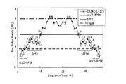
図32は系列長L = 37, 73, 149のZadoff-Chu系列(CAZAC系列)のCM特性であり、横軸は系列番号kを示す。参考のためランダム系列をπ/2-BPSK, QPSK, 16QAMで変調した場合のCMも示している。また、系列長L = 37のCAZAC系列のCM特性を図33に拡大して示している。
図32から分かるようにCAZAC系列は系列番号によって、π/2-BPSKよりも良いCM特性を示すものもあれば、16QAMよりも悪いCM特性を示すものもある。このようにCM特性が非常に大きいばらつきを持った系列を上りリンクのパイロット信号に適用した場合、端末側の増幅器のバックオフ設計が課題となる。CM特性の最悪値に合わせてユーザ端末の増幅器のバックオフを大きく設計すれば、CM特性に関係なく歪が発生することは無いが平均電力付加効率が悪くなってしまう。一方、平均値に合わせて増幅器のバックオフを設計すれば、最大あるいはそれに近い送信電力で送信する際、CM特性の悪いパイロットパターンでは1dBコンプレッションレベルを超えてしまい歪が発生し、伝送効率が劣化する。Problems of the prior art FIG. 32 shows CM characteristics of a Zadoff-Chu sequence (CAZAC sequence) with sequence length L = 37, 73, 149, and the horizontal axis indicates the sequence number k. For reference, a CM when a random sequence is modulated with π / 2-BPSK, QPSK, and 16QAM is also shown. Further, the CM characteristic of a CAZAC sequence having a sequence length L = 37 is shown in an enlarged manner in FIG.
As can be seen from FIG. 32, some CAZAC sequences show better CM characteristics than π / 2-BPSK and others show worse CM characteristics than 16QAM depending on the sequence number. When a sequence having such a large variation in CM characteristics is applied to an uplink pilot signal, back-off design of an amplifier on the terminal side becomes a problem. If the back-off of the amplifier of the user terminal is designed to be large in accordance with the worst value of the CM characteristic, distortion will not occur regardless of the CM characteristic, but the average power added efficiency will deteriorate. On the other hand, if the amplifier back-off is designed to match the average value, when transmitting at the maximum or near transmit power, the pilot pattern with poor CM characteristics will exceed the 1 dB compression level, resulting in distortion and transmission efficiency degradation. To do.
以上から、チャネル推定に適しているが、ピーク対平均電力特性のバラツキが大きいCAZAC系列などの系列を上りリンクのパイロット信号に適用する場合、どのように各ユーザ端末に対してパイロット系列を割り当てるかが課題である。従来のようにCM特性に関係なく各ユーザに任意にパイロット系列を割り当てると、大きいCM特性を持つパイロット信号の電力がバックオフを超えて非線形歪みが生じ、受信特性が劣化してしまう。
バックオフは、通常、データのCM特性を考慮して設計されているため、パイロットとしては少なくともデータのCMよりも小さいCMを持つCAZAC系列を使用することが望ましい。しかし、図32に示したように、そのような系列数は限られている。特に、π/2-BPSKよりも小さいCM特性を持つ系列は限られており、L=37の場合には6個しか存在しないことが図33からわかる。
セルあるいはセクタにおいて少ないパイロット系列(CAZAC系列)を繰り返し使用することを考慮すると、近隣のセルで同じ番号のパイロット系列を用いる場合が発生し、パイロットシンボル間で大きい相互干渉を引き起こし、チャネル推定精度の大幅な劣化を生じてしまう。
これでは、上りリンクのデータ変調にπ/2-BPSKを導入して端末の消費電力削減効果を図ったとしても、CMが大きいパイロット系列を使用することにより、その効果が失われてしまうという問題点が発生する。From the above, when applying a sequence such as a CAZAC sequence that is suitable for channel estimation but has a large variation in peak-to-average power characteristics to an uplink pilot signal, how to assign the pilot sequence to each user terminal Is an issue. If a pilot sequence is arbitrarily assigned to each user regardless of the CM characteristics as in the prior art, the power of the pilot signal having a large CM characteristic exceeds the back-off, resulting in nonlinear distortion, and the reception characteristics are degraded.
Since the back-off is usually designed in consideration of the CM characteristic of data, it is desirable to use a CAZAC sequence having a CM smaller than at least the CM of data as a pilot. However, as shown in FIG. 32, the number of such sequences is limited. In particular, it can be seen from FIG. 33 that the number of sequences having CM characteristics smaller than π / 2-BPSK is limited, and there are only 6 sequences when L = 37.
Considering the repeated use of a small number of pilot sequences (CAZAC sequences) in a cell or sector, a pilot sequence with the same number may occur in neighboring cells, causing a large mutual interference between pilot symbols and improving channel estimation accuracy. It will cause significant deterioration.
In this case, even if π / 2-BPSK is introduced for uplink data modulation to reduce the power consumption of the terminal, the effect is lost by using a pilot sequence with a large CM. A point is generated.
ところで、図32、図33より明らかなように変調方式が高次になる程(QPSK、16QAM等)、データと同時に送信できるパイロット系列数が増加する。そこで、各セルにおいて変調方式に応じたパイロット系列を使用することが提案されている(特許文献1参照)。
図34、図35はかかる変調方式に応じたパイロット系列を使用する提案方法の説明図である。図34に示すように、CAZAC系列をCM特性に基づいて順位付けしたとき、π/2-BPSK変調方式に使用できるパイロットパターン数が3、そのパイロット系列番号がk1〜k3であるとし、また、QPSK変調方式に使用できるパイロット系列数が7、そのパイロット系列番号がk4〜k10であるとする。かかる場合、図35に示す六角形セル配置において、各セルBS1〜BS7に(m,n)で示すパイロット系列を割り当てる。mは、π/2-BPSK用パイロット系列としてm番目の順位のパイロット系列を割り当てることを意味し、nはQPSK用のパイロット系列としてn番目の順位のパイロット系列を割り当てることを意味している。図35に示すように各セルにパイロット系列を割り当てると、隣接するセルにおいて使用するパ
イロット系列が異なり、かつ、同一セル内のパイロット系列が変調方式毎に異なるようになる。32 and 33, as the modulation scheme becomes higher (QPSK, 16QAM, etc.), the number of pilot sequences that can be transmitted simultaneously with data increases. Thus, it has been proposed to use a pilot sequence corresponding to the modulation scheme in each cell (see Patent Document 1).
FIG. 34 and FIG. 35 are explanatory diagrams of a proposed method that uses a pilot sequence corresponding to such a modulation scheme. As shown in FIG. 34, when CAZAC sequences are ranked based on CM characteristics, the number of pilot patterns that can be used in the π / 2-BPSK modulation scheme is 3, and the pilot sequence numbers are k 1 to k 3 . Further, it is assumed that the number of pilot sequences that can be used in the QPSK modulation scheme is 7, and the pilot sequence numbers are k 4 to k 10 . In such a case, in the hexagonal cell arrangement shown in FIG. 35, a pilot sequence indicated by (m, n) is assigned to each of the cells BS1 to BS7. m means that the m-th order pilot sequence is assigned as the π / 2-BPSK pilot sequence, and n means that the n-th order pilot sequence is assigned as the QPSK pilot sequence. As shown in FIG. 35, when a pilot sequence is assigned to each cell, a pilot sequence used in an adjacent cell is different, and a pilot sequence in the same cell is different for each modulation scheme.
図36はデータ変調方式毎に異なるパイロット系列を割り当ててDistributed FDM方式で伝送し、データをLocalized FDM方式で伝送する例であり、数字1,7は図33における系列番号である。なお、図33では、便宜上系列番号をCMの小さい順に振りなおしており、以降の説明においても、CMの小さい順に振りなおした系列番号を用いることとする。
図36では、データ変調がπ/2-BPSKのユーザU3のパイロットとして、π/2-BPSKよりCMが良いパイロット系列1を割り当て、データ変調がQPSKのユーザU1,U2,U4のパイロットとして、QPSKよりCMが良いパイロット系列7を割り当てる。このように、変調方式に応じて系列番号を選択することにより、QPSKと同時に使用できる系列数(L=37のCAZAC系列では14個)を確保し、QPSKに関してセル繰り返し数を大きくできる。すなわち、L=37のCAZAC系列では14セル毎に同一パイロット系列を繰り返し使用すればよく、セル繰り返し数は14となり大きくできる。しかし、π/2-BPSKに関しては、セル繰り返し数(L=37のCAZAC系列では6)を大きくすることはできない。
以上より本発明の目的は、CMが小さい系列番号のパイロット(パイロット系列)を隣接セルあるいは隣接セクタで使用しても干渉しないようにすることである。
本発明の別の目的は、CMが小さなパイロット系列の割り当て周波数を隣接セルあるいは隣接セクタで異ならせることにより、CMが小さなパイロット系列数を実質上に多くしてセル繰り返し数を大きくすることである。
本発明の別の目的は、チャネル推定精度を向上でき、かつ、周波数スケジューリングによりデータの送信周波数を決定できるようにすることである。
本発明の別の目的は、セル端におけるパイロットシンボルの干渉を小さくすることである。
本発明の別の目的は、同一セル内で同一パイロット系列の多重数を増やすことである。
In FIG. 36,
As described above, an object of the present invention is to prevent interference even if a pilot (pilot sequence) having a sequence number with a small CM is used in an adjacent cell or an adjacent sector.
Another object of the present invention is to increase the number of cell repetitions by substantially increasing the number of pilot sequences with a small CM by changing the allocation frequency of pilot sequences with a small CM in adjacent cells or sectors. .
Another object of the present invention is to improve channel estimation accuracy and to determine a data transmission frequency by frequency scheduling.
Another object of the present invention is to reduce the interference of pilot symbols at the cell edge.
Another object of the present invention is to increase the number of multiplexing of the same pilot sequence within the same cell.
・周波数割り当て方法
本発明の第1の態様は、無線通信システムにおける上りリンクのパイロット信号への周波数割り当て方法であり、セルにピーク対平均電力特性が異なる複数のパイロット系列を使用可能に割り当てるステップ、前記パイロット系列を周波数多重により送信する際に使用する複数の周波数を各パイロット系列に割り当てるステップ、隣接するセルあるいはセクタにおいて前記パイロット系列と周波数の対応関係を異ならせるステップを有している。
本発明の第2の態様は、無線通信システムにおける上りリンクのパイロット信号への周波数割り当て方法であり、セルあるいはセクタにおいて、使用可能なチャネル推定用パイロット系列とチャネル品質測定用パイロット系列を区別するステップ、前記チャネル推定用パイロット系列を周波数多重により送信する際に使用する複数の周波数を狭い周波数帯域から第1の周波数間隔で割り当て、チャネル品質測定用パイロット系列を周波数多重により送信する際に使用する複数の周波数を広い周波数帯域から第2の周波数間隔で割り当てるステップ、隣接するセルあるいはセクタにおいてにおいて前記各パイロット系列と周波数との対応関係を異ならせるステップを有している。
本発明の第3の態様は、無線通信システムにおける上りリンクのパイロット信号への周
波数割り当て方法であり、セルあるいはセクタにおいて、使用可能なセル境界用パイロット系列とセル中心用パイロット系列をそれぞれ区別するステップ、パイロット系列を周波数多重により送信する際に使用する複数の周波数を各パイロット系列に割り当てるステップ、隣接するセルあるいはセクタにおいて前記パイロット系列と周波数の対応関係を異ならせるステップを有している。
本発明の第4の態様は、無線通信システムにおける上りリンクのパイロット信号への周波数割り当て方法であり、セルあるいはセクタにピーク対平均電力特性が異なる複数のパイロット系列を使用可能に割り当てるステップ、前記パイロット系列を周波数多重により送信する際に使用する複数の周波数を各パイロット系列に割り当てるステップ、隣接するセルあるいはセクタにおいて前記パイロット系列をシフトさせるステップを有している。-Frequency allocation method A first aspect of the present invention is a frequency allocation method for uplink pilot signals in a radio communication system, wherein a plurality of pilot sequences having different peak-to-average power characteristics are allocated to a cell in a usable manner. A step of assigning a plurality of frequencies to be used when transmitting the pilot sequence by frequency multiplexing to each pilot sequence, and a step of making the correspondence relationship between the pilot sequence and the frequency different in adjacent cells or sectors.
A second aspect of the present invention is a method of assigning frequencies to uplink pilot signals in a wireless communication system, and distinguishing between channel estimation pilot sequences and channel quality measurement pilot sequences that can be used in a cell or sector. A plurality of frequencies used when transmitting the channel estimation pilot sequence by frequency multiplexing are assigned at a first frequency interval from a narrow frequency band, and a plurality of frequencies used when transmitting the channel quality measurement pilot sequence by frequency multiplexing. Are allocated at a second frequency interval from a wide frequency band, and the correspondence relationship between each pilot sequence and frequency is different in adjacent cells or sectors.
A third aspect of the present invention is a method for assigning frequencies to uplink pilot signals in a wireless communication system, and distinguishing between a cell boundary pilot sequence and a cell center pilot sequence that can be used in a cell or sector, respectively. , A step of assigning a plurality of frequencies used when transmitting the pilot sequence by frequency multiplexing to each pilot sequence, and a step of making the correspondence relationship between the pilot sequence and the frequency different in adjacent cells or sectors.
A fourth aspect of the present invention is a method of assigning frequencies to uplink pilot signals in a wireless communication system, wherein a plurality of pilot sequences having different peak-to-average power characteristics are allocated to cells or sectors to be usable, the pilot A step of assigning a plurality of frequencies used when transmitting the sequence by frequency multiplexing to each pilot sequence, and a step of shifting the pilot sequence in an adjacent cell or sector.
・基地局
本発明の第1態様の基地局は、ピーク対平均電力特性が異なる複数のパイロット系列のそれぞれと該パイロット系列を周波数多重により送信する際に使用する複数の周波数との対応関係を記憶する記憶部、ユーザ端末から受信した信号の受信品質を測定する測定部、前記対応関係を参照して、前記受信品質に応じたピーク対平均電力特性を有するパイロット系列をパイロットとして決定すると共に、該パイロット系列に割り当てた周波数を用いてユーザ端末が該パイロット系列を送信するようにユーザ端末に指示する指示部備え、隣接するセルあるいはセクタにおいて前記対応関係が異なるようにする。
本発明の第2態様の基地局は、チャネル推定用パイロット系列とチャネル品質測定用パイロット系列のそれぞれと該パイロット系列を周波数多重により送信する際に使用する複数の周波数との対応関係を記憶する記憶部、前記対応関係を参照して、チャネル品質測定時にチャネル品質測定用パイロット系列を、チャネル推定時にチャネル推定用パイロット系列をそれぞれパイロットとして決定すると共に、該パイロット系列に割り当てた周波数を用いてユーザ端末が該パイロット系列を送信するようにユーザ端末に指示する指示部、チャネル品質測定用パイロット系列を用いてチャネル品質を測定する測定部、チャネル品質が良い周波数帯域を求めてユーザ端末のデータ送信用周波数を決定するデータ送信周波数決定部、チャネル推定用パイロット系列を用いてチャネル推定を行うチャネル推定部、チャネル推定結果に基づいて周波数等化制御を行う周波数等化部を備え、前記チャネル推定用パイロット系列を周波数多重により送信する際に使用する複数の周波数を狭い周波数帯域から第1の周波数間隔で割り当て、チャネル品質測定用パイロット系列を周波数多重により送信する際に使用する複数の周波数を広い周波数帯域から第2の周波数間隔で割り当て、かつ、隣接するセルあるいはセクタにおいて前記対応関係を異ならせる。
本発明の第3態様の基地局は、セル境界用パイロット系列とセル中心用パイロット系列のそれぞれと該パイロット系列を周波数多重により送信する際に使用する複数の周波数との対応関係を記憶する記憶部、ユーザ端末がセル境界に存在するか否かを判定する判定部、前記対応関係を参照して、ユーザ端末がセル境界に存在するとき、セル端用パイロット系列を、ユーザ端末がセル境界に存在しないとき、セル中心用パイロット系列をそれぞれパイロットとして決定すると共に、該パイロット系列に割り当てた周波数を用いてユーザ端末が該パイロット系列を送信するようにユーザに指示する指示部を備え、隣接するセルあるいはセクタにおいて前記対応関係が異なるようにする。
本発明の第4態様の基地局は、ピーク対平均電力特性が異なる複数のパイロット系列のそれぞれと該パイロット系列を周波数多重により送信する際に使用する複数の周波数との対応関係を記憶する記憶部、ユーザ端末から受信した信号の受信品質を測定する測定部、前記対応関係を参照して、前記受信品質に応じたピーク対平均電力特性を有するパイロット系列をパイロットとして決定すると共に該パイロット系列をシフトするか否かを決定し、該パイロット系列に割り当てた周波数を用いてユーザ端末が該パイロット系列をシフトし、あるいはシフトせずに送信するようにユーザに指示する指示部を備えている。Base station The base station according to the first aspect of the present invention stores a correspondence relationship between each of a plurality of pilot sequences having different peak-to-average power characteristics and a plurality of frequencies used when transmitting the pilot sequences by frequency multiplexing. A storage unit, a measurement unit that measures reception quality of a signal received from a user terminal, a pilot sequence having a peak-to-average power characteristic according to the reception quality is determined as a pilot with reference to the correspondence relationship, An instruction unit for instructing the user terminal to transmit the pilot sequence using the frequency allocated to the pilot sequence is provided so that the correspondence relationship is different in adjacent cells or sectors.
The base station according to the second aspect of the present invention stores a correspondence relationship between each of the channel estimation pilot sequence and the channel quality measurement pilot sequence and a plurality of frequencies used when the pilot sequence is transmitted by frequency multiplexing. Referring to the correspondence relationship, the channel quality measurement pilot sequence is determined at the time of channel quality measurement, and the channel estimation pilot sequence is determined as a pilot at the time of channel estimation, and the user terminal using the frequency allocated to the pilot sequence An instruction unit for instructing a user terminal to transmit the pilot sequence, a measurement unit for measuring channel quality using a pilot sequence for channel quality measurement, and a frequency for data transmission of the user terminal for obtaining a frequency band with good channel quality Data transmission frequency determining unit to determine the channel estimation pie A channel estimation unit that performs channel estimation using a channel sequence and a frequency equalization unit that performs frequency equalization control based on a channel estimation result, and a plurality of channels used when transmitting the channel estimation pilot sequence by frequency multiplexing Are allocated at a first frequency interval from a narrow frequency band, a plurality of frequencies used when transmitting a channel quality measurement pilot sequence by frequency multiplexing are allocated at a second frequency interval from a wide frequency band, and adjacent The correspondence relationship is made different in each cell or sector.
A base station according to a third aspect of the present invention stores a correspondence relationship between each of a cell boundary pilot sequence and a cell center pilot sequence and a plurality of frequencies used when the pilot sequence is transmitted by frequency multiplexing. A determination unit that determines whether or not a user terminal is present at a cell boundary; referring to the correspondence relationship, when the user terminal is present at a cell boundary, a pilot sequence for a cell edge is present; If not, a cell center pilot sequence is determined as each pilot, and an instruction unit that instructs the user terminal to transmit the pilot sequence using a frequency allocated to the pilot sequence is provided. The correspondence is made different in each sector.
The base station according to the fourth aspect of the present invention stores a correspondence relationship between each of a plurality of pilot sequences having different peak-to-average power characteristics and a plurality of frequencies used when transmitting the pilot sequences by frequency multiplexing. A measurement unit that measures the reception quality of a signal received from a user terminal, refers to the correspondence relationship, determines a pilot sequence having peak-to-average power characteristics according to the reception quality as a pilot, and shifts the pilot sequence And an instruction unit for instructing the user to use the frequency assigned to the pilot sequence to shift the pilot sequence or transmit the pilot sequence without shifting.
(A)第1実施例
(a)パイロット系列への周波数割り当て法
図1〜図3は第1実施例におけるパイロット系列に対する周波数割り当て法の説明図であり、横軸は周波数、数値はパイロット系列番号である。図1〜図3の例では、4つの隣接するセル1A,1B,1C,1Dがパイロット系列1,7,8,9(図33参照)を使用可能としている。パイロット系列1はCMがπ/2-BPSKより小さいため任意の変調方式に使用でき、パイロット系列7,8,9はCMがπ/2-BPSKより大きく、QPSKより小さいため、π/2-BPSK以外の変調方式に使用できる。本発明の各実施例はセルに限らずセクタにも適用できるが以後の説明ではセルに適用する場合についてのみ説明する。
本発明では、パイロット系列のセル繰り返し数を大きくするために、パイロット系列を周波数多重により送信する際に使用する複数の周波数を各パイロット系列に割り当て、かつ、パイロット系列と周波数の対応関係を4つの隣接セル1A,1B,1C,1Dにおいて異ならせている。基地局は、設定されたパイロット系列と周波数帯の対応関係(パイロット系列割り当てテーブル)を下り報知チャネルなどを用いてセル内のユーザ端末(移動端末)に報知する。(A) First Embodiment (a) Frequency Allocation Method for Pilot Sequence FIGS. 1 to 3 are explanatory diagrams of a frequency allocation method for pilot sequences in the first embodiment, where the horizontal axis is frequency and the numerical value is pilot sequence number. It is. In the example of FIGS. 1 to 3, four
In the present invention, in order to increase the number of cell repetitions of the pilot sequence, a plurality of frequencies used when transmitting the pilot sequence by frequency multiplexing are assigned to each pilot sequence, and the correspondence relationship between the pilot sequence and the frequency is The
図1(A)、(B)はパイロット系列をDistributed FDMで多重して送信する例である。図1(A)ではセル1A,1B,1C,1Dにおいてパイロット系列1,7,8,9が周期的に各周波数に割り当てられており、セル毎にパイロット系列と周波数との対応関係が1周波数ずれている。図1(B)ではセル1A,1B,1C,1Dにおいてパイロット系列1が4周波数間隔で各周波数に割り当てられ、セル毎にパイロット系列1の割り当て周波数がずれている。又、残りの周波数には、セル1A,1B,1C,1Dにおいてパイロット系列7,8,9,10がそれぞれ割り当てられている。
図2はパイロット系列をLocalized FDMで多重して送信する例であり、セル1A,1B,1C,1D毎にパイロット系列と周波数との対応関係がずれている。
図3は1フレームに複数のパイロットブロックが存在する場合、パイロットブロック毎に異なるFDM方式(Distributed FDM、Localized FDM)でパイロット系列を多重して伝送する例である。なお、各FDM方式においてセル毎に周波数とパイロット系列の対応関係をずらす必要がある。
図1(A)のパイロット系列の割り当て法によれば、4セル1A,1B,1C,1Dに同一のパイロット系列グループ(系列番号1,7,8,9)を使用することができる。さて、図33に示したL=37のCAZAC系列では、π/2-BPSKよりも小さいCM特性を持つ系列が6個存在し(系列1〜6)、QPSKよりも小さいCM特性を持つ系列は14個存在する(系列7〜20)。そこで、図4に示すようにパイロット系列を6グループに分けると、図1(A)の場合と同様に各グループのパイロット系列をそれぞれ4セルに使用することができる。グループ1〜6の4つのセルをそれぞれ1A〜1D, 2A〜2D, 3A〜3D, 4A〜4D, 5A〜5D, 6A〜6Dとすれば、図5に示すようにセルを配置することができる。従来、6セル毎にπ/2-BPSKよりも小さいCM特性を持つ系列1〜6を繰り返し使用していたため(セル繰り返し数=6)、近隣セル間でパイロットシンボルの干渉が生じていたが、図4のようにグループ化することによりセル繰り返し数を実質的に24にでき、近隣セル間でパイロットシンボルの干渉が生じないようにできる。FIGS. 1A and 1B are examples in which pilot sequences are multiplexed and transmitted by Distributed FDM. In FIG. 1A,
FIG. 2 is an example in which pilot sequences are multiplexed and transmitted by Localized FDM, and the correspondence relationship between pilot sequences and frequencies is shifted for each
FIG. 3 shows an example in which when a plurality of pilot blocks exist in one frame, the pilot sequences are multiplexed and transmitted by different FDM schemes (Distributed FDM, Localized FDM) for each pilot block. In each FDM system, it is necessary to shift the correspondence between frequency and pilot sequence for each cell.
According to the pilot sequence assignment method of FIG. 1A, the same pilot sequence group (
具体例として、システムでπ/2-BPSKとQPSKの二つの変調方式を持つとし、π/2-BPSK以下のCMを持つCAZAC系列数をN1、π/2-BPSK以上QPSK以下のCMを持つCAZACの系列数をN2とする。また、FDMの多重数をRとし、そのうち、π/2-BPSKへの割り当て数をR1、QPSKへの割り当て数をR2とする(R=R1+R2)。この時、本発明のパイロット系列の周波数割り当て法によれば、それぞれの繰り返し数は
S1=R [N1/R1] (π/2-BPSKの繰り返し数)
S2=R[N2/R2] (QPSKの繰り返し数)
となる。ただし、[x]は小数点以下を切捨てた整数を表す。このように本発明のパイロット系列割り当て法によれば、元の繰り返し数N1およびN2に対して繰り返し数を大きくすることが出来る。通常N1が小さいこと、つまり、CMがπ/2-BPSKより小さいCAZAC系列の繰り返し数が少ないこと、が問題となるので、R1をR2に対して小さくとることにより、問題を解決できる。なお、デメリットとして、セルにおいてπ/2-BPSKの同時送信端末の数が制限されるという問題がある(最大Rに対してR1となる)。しかし、π/2-BPSKで通信を行う端末はセル端(セル境界)近辺に存在するなど、特別な状況下にあり、通常同時に多数の端末がπ/2-BPSKで通信を行う状況は起きにくいと考えられる。一方、CMがQPSKより小さいCAZAC系列はどの周波数領域にも割り当てることも可能であるため、QPSKに対する制限は生じない。
数値例を挙げて説明すると、L=37、R=4の場合、図33を参照すると、N1=6、N2=14となり、R1=1、R2=3とすると、S1=24、S2=16と計算される。つまり、特許文献1で提案した技術と比較して、CAZAC系列のセル繰り返し数を6→24および14→16と向上できたことになる。この場合のセル配置が図5のようになる。As a specific example, assume that the system has two modulation schemes, π / 2-BPSK and QPSK, and that the number of CAZAC sequences with CM of π / 2-BPSK or less is N1, and CM of π / 2-BPSK or more and QPSK or less The number of CAZAC series is N2. Also, the FDM multiplexing number is R, of which the allocation number to π / 2-BPSK is R1, and the allocation number to QPSK is R2 (R = R1 + R2). At this time, according to the frequency allocation method of the pilot sequence of the present invention, each repetition number is
S1 = R [N1 / R1] (Repetition number of π / 2-BPSK)
S2 = R [N2 / R2] (number of QPSK repetitions)
It becomes. However, [x] represents an integer with the decimal part truncated. Thus, according to the pilot sequence allocation method of the present invention, the number of repetitions can be increased with respect to the original number of repetitions N1 and N2. Usually, N1 is small, that is, the number of CAZAC sequence repetitions smaller than π / 2-BPSK is a problem. Therefore, the problem can be solved by making R1 smaller than R2. As a demerit, there is a problem that the number of π / 2-BPSK simultaneous transmission terminals in the cell is limited (R1 with respect to the maximum R). However, terminals that communicate with π / 2-BPSK are under special circumstances, such as being near the cell edge (cell boundary). Usually, many terminals communicate with π / 2-BPSK at the same time. It is considered difficult. On the other hand, since a CAZAC sequence with CM smaller than QPSK can be assigned to any frequency domain, there is no restriction on QPSK.
In the case of L = 37 and R = 4, referring to FIG. 33, N1 = 6, N2 = 14, and R1 = 1, R2 = 3, S1 = 24, S2 = 16. Is calculated. That is, compared with the technique proposed in
(b)第1実施例の基地局
図6は第1実施例の基地局の構成図であり、ユーザ端末(以後ユーザという)がパイロットとデータをそれぞれDistributed FDM方式で送信する場合である。なお、パイロットとデータをそれぞれDistributed FDM方式で送信する場合には、パイロットとデータの送信周波数は同じになる。
メモリ10にはセルにおいて使用可能なパイロット系列と該パイロット系列に割り当てた周波数帯との対応関係(パイロット系列割当てテーブルPSAT)が保存されている。例えば図1(A)に示す対応関係がパイロット系列割当てテーブルPSATとしてメモリ10に保存される。
無線部11は送信機、受信機を内蔵しており、受信機はユーザからの受信信号を無線周波数からベースバンド周波数に周波数変換して上り信号ベースバンド処理部12に入力する。ベースバンド処理部12は入力信号(図25参照)より時分割多重データを復調し、データ/パイロット分離部13は該時分割多重データよりパイロットとデータ分離する。SIR測定部は受信信号のSIRを測定し、スケジューラ15に入力する。(b) Base station according to the first embodiment FIG. 6 is a block diagram of the base station according to the first embodiment, in which a user terminal (hereinafter referred to as a user) transmits pilot and data in the distributed FDM scheme. In addition, when transmitting pilot and data by Distributed FDM, respectively, the transmission frequency of pilot and data is the same.
The
The
スケジューラ15は図7の処理フローに従ってユーザの変調方式、パイロット系列番号などを決定する。すなわち、スケジューラ15は測定されたSIRに基づいてユーザ変調方式と符号化率を適応的に決定する(ステップ101)。SIRが大きければ変調方式としてQPSKを選択し、小さければπ/2-BPSKを選択する。また、SIRが大きければ符号化率を大きくし、小さければ符号化率を小さくする。ついで、スケジューラ15はパイロット系列割り当てテーブルPSTLを参照し、ステップ101で決定した変調方式よりCMが小さなパイロット系列を使用パイロット系列として決定する(ステップ102)。すなわち、テーブルPSTLを参照すると、セルにパイロット系列1,7,8,9が割り当てられており、パイロット系列1がπ/2-BPSKよりCMが小さく、パイロット系列1,7,8,9がQPSKよりCMが小さいから、変調方式がπ/2-BPSKであればパイロット系列1を使用パイロット系列として決定し、変調方式がQPSKであればパイロット系列1,7,8,9のいずれかを使用パイロット系列として決定する。
ついで、スケジューラ15はテーブルPSATを参照してパイロット系列が割り当てられている複数の周波数を求める(ステップ103)。これら周波数はユーザがDistributed FDM方式でパイロット及びデータを送信する際に使用する周波数となる。しかる後、ステップ101〜103で決定した変調方式、符号化率、パイロット系列番号、パイロット/データ周波数を下りベースバンド処理部16に入力する。下りベースバンド処理部16は例えばOFDM送信処理を行なって無線部11より上記データをユーザに送信する(ステップ104)。これにより、ユーザは基地局からの指示に基づいてパイロットとデータの時分割多重データを送信可能になる。
ユーザより信号を受信すると、ベースバンド処理部12は時分割多重データを復調し、データ/パイロット分離部13は外時分割多重データよりパイロットとデータ分離し、それぞれチャネル推定部17、周波数等化部18に入力する。The
Next, the
When the signal is received from the user, the
チャネル推定部17および周波数等化部18は図8に示す構成を備えて周波数等化制御を行なう。チャネル推定部17においてFFT部17aはN×M サンプルのパイロットにFFT処理を施してN×M の周波数成分を発生し、周波数別チャネル推定部17bは該N×M 個の周波数成分と既知パイロットのN×M 個の周波数成分を用いて周波数毎にチャネル推定を行なってチャネル補償信号を周波数等化部18のチャネル補償部に入力する。
周波数等化部18のFFT部18aはN×M サンプルデータにFFT処理を施してN×M 個の周波数成分を発生してチャネル補償部18bに入力する。チャネル補償部18bはFFT部18aから出力するN×M 個の周波数成分に周波数毎にチャネル補償信号を乗算してチャネル補償し、デマッピング部18cはDistributed FDM方式でデータ送信する際に使用した周波数に基づいてN×M 個の周波数成分よりN個の周波数成分を選択してIFFT処理部18dに入力する(デマッピング)。IFFT処理部18dはN個の周波数成分にIFFT処理を施して時間信号にして出力する。復調部19は符号化されたデータを復調し、チャネル復号部2
0は復号処理をして出力する。
なお、基地局がユーザに下り報知チャネルによりパイロット系列割り当てテーブルPSATを報知している場合には、基地局よりパイロット及びデータの送信周波数データをユーザに送らなくても良い。ユーザはパイロット系列番号からテーブルPSATを参照してパイロット及びデータの送信周波数を求めることができるからである。また、基地局がユーザに割り当てた周波数を通知し、ユーザは該周波数からテーブルPSATを参照してパイロット系列番号を決定することも可能である。The
The
0 is decoded and output.
When the base station broadcasts the pilot sequence allocation table PSAT to the user through the downlink broadcast channel, the base station does not need to send pilot and data transmission frequency data to the user. This is because the user can obtain the pilot and data transmission frequencies from the pilot sequence number by referring to the table PSAT. In addition, the base station notifies the frequency assigned to the user, and the user can determine the pilot sequence number from the frequency by referring to the table PSAT.
以上では、ユーザがパイロットとデータをそれぞれDistributed FDM方式で送信する場合であるが、ユーザがパイロットとデータをそれぞれLocalized FDM方式で送信する場合もパイロットとデータの送信周波数は同じになり、同様の制御が行われる。
また、ユーザがパイロットをDistributed FDM方式で送信し、データをLocalized FDM方式で送信する場合、パイロットとデータの送信周波数は同じにならない。この場合、基地局はパイロットの送信周波数を図6で説明したように決定し、データの送信周波数を周波数スケジューリングにより決定する。The above is the case where the user transmits pilot and data using the Distributed FDM method. However, when the user transmits the pilot and data using the Localized FDM method, the pilot and data transmission frequencies are the same, and similar control is performed. Is done.
In addition, when the user transmits a pilot using the Distributed FDM scheme and transmits data using the Localized FDM scheme, the transmission frequencies of the pilot and the data are not the same. In this case, the base station determines the pilot transmission frequency as described in FIG. 6, and determines the data transmission frequency by frequency scheduling.
図9はユーザがパイロットをDistributed FDM方式で送信し、データをLocalized FDM方式で送信する場合のスケジューラの処理フローである。
SIR測定部14はDistributed FDM方式でユーザより送られてくるパイロット信号に基づいて周波数毎にSIRを測定する。スケジューラ15は周波数毎のSIRを参照して通信状態が良好な周波数帯を求め、該周波数帯よりデータ送信周波数を決定する(周波数スケジューリング、ステップ201)。以後、スケジューラ15は図7のステップ101〜104と同様の処理を行なって、変調方式、符号化率、パケット系列番号、パイロット送信周波数を決定し、これらとステップ201で求めたデータ送信周波数をユーザに送信する(ステップ202〜205)。FIG. 9 is a processing flow of the scheduler when the user transmits a pilot by the Distributed FDM method and transmits data by the Localized FDM method.
The
(c)第1実施例のユーザ端末
図10は第1実施例のユーザ端末の構成図である。
無線部31は送信機、受信機を内蔵しており、受信機は受信信号を無線周波数からベースバンド周波数に周波数変換して下り信号ベースバンド処理部32に入力する。ベースバンド処理部32は入力信号に受信処理、例えば、OFDM受信処理を行なってデータ復調部33に入力し、データ復調部は受信データを復調する。チャネル符号化部34は基地局から指示された符号化率に基づいて符号化を行い、データ変調部35は基地局から指示された変調方式でデータ変調を行い、パイロット系列発生部36は基地局から指示されたパイロット系列番号のパイロットを発生する。
周波数割り当て部37は図11(A)に示す構成を備え、Distributed FDM方式のデータ送信をシングルキャリア伝送により実現する。FFT部37aはNサンプルの送信データa0,a1,….aN-1にFFT処理を施して周波数成分A0,A1,….AN-1を発生し、マッピング部37bはデータ送信周波数にA0,A1,….AN-1をマッピングし、0を残りの周波数にマッピングしてIFFT部37cに入力する。IFFT部37cはM×N個の周波数成分にIFFT処理を施して送信データa0〜aN-1を時間軸上でM回繰り返すデータ列にして出力する。
なお、マッピング部37bはFFTされた送信信号を、Localized FDMの場合は連続したサブキャリア(周波数)にマッピングし、Distributed FDMの場合は一定間隔を置いたサブキャリアにマッピングし、しかる後、IFFTにより再び時間領域の信号に変換して出力する。(c) User terminal of the first embodiment FIG. 10 is a block diagram of the user terminal of the first embodiment.
The
The
The
周波数割り当て部38は図11(B)に示す構成を備え、Distributed FDM方式の送信をシングルキャリア伝送により実現する。FFT部38aはNサンプルのパイロットp0,p1,….pN-1にFFT処理を施して周波数成分B0,B1,….BN-1を発生し、マッピング部38bはパイロット送信周波数にB0,B1,….BN-1をマッピングし、0を残りの周波数にマッピングしてIFFT部
38cに入力する。IFFT部38cはM×N個の周波数成分にIFFT処理を施してパイロットp0〜pN-1を時間軸上でM回繰り返すデータ列にして出力する。
データ/パイロット多重部39は各周波数割り当て部37,38から出力するデータ及びパイロットを時間多重して無線部31に入力する。無線部31の送信機はベースバンド信号を無線周波数に周波数変換した後、増幅して基地局に送信する。The
The data /
図12は基地局がユーザに下り報知チャネルによりパイロット系列割り当てテーブルPSATを報知している場合のユーザ端末の構成図である。
図10のユーザ端末と異なる点は、(1)保存部40がパイロット系列割り当てテーブルPSATを保存している点、(2)周波数決定部41が基地局から通知されたパイロット系列番号からパイロット系列割り当てテーブルPSATを用いて、パイロット及びデータを送信する際に使用する周波数を決定して周波数割り当て部37,38に入力している点である。
第1実施例によれば、隣接するセルで同じ系列番号のパイロットを使用していても使用帯域を異ならせることにより、同じ系列番号のパイロット同士が干渉しないようにできる。この結果、第1実施例によれば、CMが小さなパイロット系列数を実質上に多くできセル繰り返し数を大きくすることができる。FIG. 12 is a block diagram of the user terminal when the base station broadcasts the pilot sequence allocation table PSAT to the user through the downlink broadcast channel.
10 differs from the user terminal in FIG. 10 in that (1) the
According to the first embodiment, pilots having the same sequence number can be prevented from interfering with each other by using different bands even if pilots having the same sequence number are used in adjacent cells. As a result, according to the first embodiment, the number of pilot sequences with a small CM can be substantially increased, and the number of cell repetitions can be increased.
(B)第2実施例
パイロットには、チャネル推定と適応変調スケジューリングのためのSIR測定の2つの使用目的がある。チャネル推定用パイロットはデータと同じだけの帯域があれば十分であるが、正確なチャネル推定をするために高品質であることが要求される。一方、SIR測定用パイロットは、周波数スケジューリングするために広い帯域幅が必要であるが、品質に対する要求はチャネル推定ほどではない。このため、使用目的を考慮してパイロットを区別して送信すればパイロットの送信効率を向上することができる。
図13はチャネル推定用パイロットとSIR測定用パイロットに対する周波数割り当て法の説明図であり、横軸は周波数である。CE0〜CE3はチャネル推定用パイロット系列であり、CQ0〜CQ5はSIR測定用パイロット系列である。チャネル推定用パイロット系列CE0〜CE3には狭い帯域F0〜F3の周波数が所定周波数間隔で割り当てられているが、SIR測定用パイロット系列CQ0〜CQ5には周波数帯域全体にわたって周波数が別の周波数間隔で割り当てられている。
チャネル推定には高品質が要求されるためチャネル推定用パイロット系列CE0〜CE3としてCMの小さい系列を使用し、SIR測定用パイロット系列CQ0〜CQ5としてCMの比較的大きい系列を使用し、隣接セル間で各パイロット系列CE0〜CE3、CQ0〜CQ5に割り当てる周波数を異ならせている。また、SIR測定用パイロットはチャネル推定用パイロットよりも品質が低くても良いので送信電力を小さくすることによって、チャネル推定用パイロットへの干渉を減らすことが可能である。(B) Second embodiment The pilot has two purposes of use: SIR measurement for channel estimation and adaptive modulation scheduling. The channel estimation pilot need only have the same bandwidth as the data, but is required to have high quality in order to perform accurate channel estimation. On the other hand, the pilot for SIR measurement requires a wide bandwidth for frequency scheduling, but the quality requirement is not as high as channel estimation. For this reason, if the pilot is distinguished and transmitted in consideration of the purpose of use, the transmission efficiency of the pilot can be improved.
FIG. 13 is an explanatory diagram of the frequency allocation method for the channel estimation pilot and the SIR measurement pilot, and the horizontal axis represents the frequency. CE0 to CE3 are channel estimation pilot sequences, and CQ0 to CQ5 are SIR measurement pilot sequences. Channel estimation pilot sequences CE0 to CE3 are assigned frequencies in narrow bands F0 to F3 at predetermined frequency intervals, but SIR measurement pilot sequences CQ0 to CQ5 are assigned frequencies across the entire frequency band at different frequency intervals. It has been.
Since high quality is required for channel estimation, a channel with a small CM is used as the pilot sequence for channel estimation CE0 to CE3, and a sequence with a relatively large CM is used as the pilot sequences for SIR measurement CQ0 to CQ5. Thus, the frequencies assigned to the pilot sequences CE0 to CE3 and CQ0 to CQ5 are different. Further, since the quality of the SIR measurement pilot may be lower than that of the channel estimation pilot, it is possible to reduce interference with the channel estimation pilot by reducing the transmission power.
図14は第2実施例の基地局の構成図であり、図6の第1実施例の基地局と同一部分には同一符号を付している。異なる点は、(1)メモリ10に使用可能なチャネル推定用パイロット系列番号とSIR測定用パイロット系列番号とこれらパイロット系列に割り当てた周波数との対応関係(パイロット系列割当てテーブルPSAT)が保存されている点、(2)パイロット分離部51を設け、SIR測定用パイロットとチャネル推定用パイロットとを分離してSIR測定部14とチャネル推定部17に入力する点である。
ユーザ端末はデータ通信に先立って基地局より所定のSIR測定用パイロット系列番号が指定され、該系列番号のパイロットをdistributed FDM方式により基地局に送信する。
基地局のベースバンド処理部12は入力データを復調し、データ/パイロット分離部13は受信データよりパイロットを分離し、パイロット分離部51はパイロットよりSIR測定用パイロットを分離してSIR測定部14に入力する。SIR測定部14はDistributed FDM方式によりユーザより送られてきた該SIR測定用パイロット信号に基づいて周波数毎にSIRを測定する。FIG. 14 is a block diagram of the base station according to the second embodiment, and the same reference numerals are given to the same parts as those of the base station according to the first embodiment of FIG. The differences are as follows: (1) Correspondence relationship between pilot sequence numbers for channel estimation, pilot sequence numbers for SIR measurement, and frequencies allocated to these pilot sequences (pilot sequence allocation table PSAT) is stored in the
Prior to data communication, the user terminal is assigned a predetermined SIR measurement pilot sequence number from the base station, and transmits the pilot of the sequence number to the base station using the distributed FDM scheme.
The
スケジューラ15は周波数毎のSIRを参照して通信状態が良好な周波数帯を求め、ユーザがデータをDistributed FDM方式で送信する際に使用する周波数を決定する(周波数スケジューリング)。また、スケジューラ15はテーブルPSATを参照して該データ送信用の周波数が割り当てられているチャネル推定用パイロット系列を求め、該パイロット系列に割り当てられている周波数をパイロット送信周波数として決定する。以後、スケジューラ15は第1実施例と同様に変調方式、符号化率を決定し、上記決定したデータ送信用周波数、パイロット系列番号、パイロット送信用周波数、変調方式、符号化率をユーザに指示する。ユーザは基地局からの指示に基づいてチャネル推定用パイロットとデータの時分割多重データを送信する。
基地局のベースバンド処理部12はユーザから送信された信号より時分割多重データを復調し、データ/パイロット分離部13は該時分割多重データよりパイロットとデータを分離し、それぞれパイロット分離部51と周波数等化部18に入力する。パイロット分離部51はチャネル推定用パイロットを分離してチャネル推定部17に入力する。チャネル推定部17および周波数等化部18は第1実施例と同様に周波数等化制御を行ない、復調部19は等化部出力より符号化されているデータを復調し、チャネル復号部20は該符号化されているデータを復号して出力する。
なお、基地局がユーザに下り報知チャネルによりパイロット系列割り当てテーブルPSATを報知している場合には、基地局よりパイロット及びデータの送信周波数データをユーザに送らなくても良い。ユーザはパイロット系列番号からテーブルPSATを参照してパイロット及びデータの送信周波数を求めることができるからである。また、基地局がユーザに割り当てた周波数を通知し、ユーザは該周波数からテーブルPSATを参照してパイロット系列番号を決定することも可能である。The
The
When the base station broadcasts the pilot sequence allocation table PSAT to the user through the downlink broadcast channel, the base station does not need to send pilot and data transmission frequency data to the user. This is because the user can obtain the pilot and data transmission frequencies from the pilot sequence number by referring to the table PSAT. In addition, the base station notifies the frequency assigned to the user, and the user can determine the pilot sequence number from the frequency by referring to the table PSAT.
第2実施例のユーザ端末は、図10の第1実施例と同様の構成にすることができる。また、報知チャネルでパイロット系列割り当てテーブルPSATが基地局よりユーザ端末に報知されている場合には、ユーザ端末は図15に示す構成になる。
図15において、図10のユーザ端末と異なる点は、(1)保存部40がパイロット系列割り当てテーブルPSATを保存している点、(2)周波数決定部41が基地局から通知されたパイロット系列番号からパイロット系列割当テーブルPSATを参照してパイロットをdistributed FDM方式で送信する際に使用する周波数を決定して周波数割り当て部38に入力している点である。
第2実施例によれば、チャネル推定精度を向上でき、しかも、周波数スケジューリングにより良好な周波数帯域を用いてデータ送信ができる。また、隣接するセルでチャネル推定用パイロットとしてCMが小さなパイロット系列を使用しても、使用帯域を異ならせることにより、同じ系列番号のパイロット同士が干渉しないようにできる。The user terminal of the second embodiment can have the same configuration as that of the first embodiment of FIG. When the pilot sequence allocation table PSAT is broadcast from the base station to the user terminal using the broadcast channel, the user terminal has the configuration shown in FIG.
15 differs from the user terminal of FIG. 10 in that (1) the
According to the second embodiment, channel estimation accuracy can be improved, and data transmission can be performed using a good frequency band by frequency scheduling. Further, even when a pilot sequence having a small CM is used as a channel estimation pilot in an adjacent cell, it is possible to prevent pilots having the same sequence number from interfering with each other by using different bandwidths.
(C)第3実施例
セル間の干渉は異なる系列番号のパイロット信号間でも生じる。これは同じ系列番号の干渉ほど大きくはないが、特にセル端(セル境界)にいるユーザにとっては無視できないものとなる。このため、セル端に存在するユーザに関しては隣接するセルでパイロット周波数が重ならないようにする必要がある。
図16は第3実施例のパイロットに対する周波数割り当て例であり、横軸は周波数である。図16の例では、パイロット周波数が隣接セルとの境界(セル端)において重ならないようにしている。各セル1A〜1Dのセル端におけるパイロットは異なる系列でもよいが、図では系列番号1のパイロット系列を使用するものとし、該パイロット系列に割り当てる周波数をセル毎に異ならせている。また、各セル1A〜1Dのセル端以外の領域(セル中心という)におけるパイロットとして系列番号7,8,9のパイロット系列を使用するものとし、該パイロット系列に割り当てる周波数をセル毎に異ならせている。
データ変調方式としてπ/2-BPSKを用いるユーザはセル端にいることが多いため、CMの
低いCAZAC系列をセル端のパイロット系列とする。このため、図16の例ではπ/2-BPSK よりCMが小さな番号1のCAZAC系列をセル端のパイロット系列として使用している。
以上ではパイロットをDistributed FDMで多重して送信する例であるが、パイロットをLocalized FDMで多重して送信する場合も、同様にセル端ユーザに関して隣接セル間でパイロット周波数が重ならないようにすることができる。(C) Third Embodiment Inter-cell interference also occurs between pilot signals with different sequence numbers. This is not as great as the interference with the same sequence number, but it cannot be ignored especially for users at the cell edge (cell boundary). For this reason, it is necessary to prevent pilot frequencies from overlapping in adjacent cells for users existing at the cell edge.
FIG. 16 is an example of frequency allocation for pilots in the third embodiment, and the horizontal axis represents frequency. In the example of FIG. 16, the pilot frequencies are prevented from overlapping at the boundary (cell edge) with the adjacent cell. The pilots at the cell edges of the
Since users using π / 2-BPSK as a data modulation scheme are often at the cell edge, a CAZAC sequence with a low CM is used as a pilot sequence at the cell edge. Therefore, in the example of FIG. 16, the CAZAC sequence of
The above is an example in which pilots are multiplexed and transmitted by Distributed FDM. However, even when pilots are multiplexed and transmitted by Localized FDM, it is possible to prevent pilot frequencies from overlapping between adjacent cells in the same way for cell edge users. it can.
図17は第3実施例の基地局の構成図であり、図6の第1実施例の基地局と同一部分には同一符号を付している。異なる点は、(1)メモリ10にセル端で使用可能なパイロット系列番号と、セル中心で使用可能なパイロット系列番号と、これら番号のパイロット系列に割り当てた周波数との対応関係(パイロット系列割当てテーブルPSAT)が保存されている点、(2)セル端判定部61を設け、スケジューラ15がセル端に存在するユーザにセル端で使用可能なパイロット系列を割り当て、セル中心にいるユーザにはセル中心で使用可能なパイロット系列を割り当てる点である。セル端判定部61はSIR測定部で測定された受信SIRの大小に基づいてユーザがセル端に存在するか判定する。たとえば、受信SIRが設定値以下であればユーザはセル端に存在すると判定する。
FIG. 17 is a block diagram of a base station according to the third embodiment. Components identical with those of the base station according to the first embodiment shown in FIG. The difference is that (1) the correspondence between pilot sequence numbers that can be used at the cell edge in the
図18はスケジューラの処理フローである。SIR測定部14はDistributed FDM方式でユーザより送られてくるパイロット信号に基づいて周波数毎にSIRを測定してスケジューラ15に入力すると共に受信SIRを計算してセル端判定部61に入力する(ステップ301)。スケジューラ15は周波数毎のSIRを参照して通信状態が良好な周波数帯を求め、該周波数帯よりデータ送信周波数を決定する(周波数スケジューリング、ステップ302)。
セル端判定部61は受信SIRに基づいてユーザがセル端に存在するか否かを判定する(ステップ303)。スケジューラ15は、ユーザがセル端に存在すれば、テーブルPSATを参照してセル端で使用可能なパイロットの系列番号を決定し(ステップ304)、セル端に存在しなければセル中心で使用可能なパイロットの系列番号を決定する(ステップ305)。以後、スケジューラ15は、データ変調方式、符号化率を決定し(ステップ306)、最後に、データ周波数、パイロット系列番号、データ変調方式、符号化率等をユーザに通知する(ステップ307)。なお、第3実施例のユーザ端末は、図15の第2実施例と同様の構成にできる。
第3実施例によれば、セル端におけるパイロットシンボルの干渉を小さくできる。また、セル端のパイロットとしてCMが小さなパイロット系列を使用しても、隣接セル間で使用帯域を異ならせることにより、セル繰り返し数を大きくできる。FIG. 18 is a processing flow of the scheduler. The
The cell
According to the third embodiment, pilot symbol interference at the cell edge can be reduced. Further, even when a pilot sequence having a small CM is used as a pilot at the cell edge, the number of cell repetitions can be increased by making the use band different between adjacent cells.
(D)第4実施例
CAZAC系列と任意の時間シフトしたCAZAC系列との相関(自己相関)は0であり、十分な時間シフトをしたCAZAC系列は異なる系列として扱うことが可能である。このため、隣接する2つのセルで同一のCAZAC系列をパイロット系列として使用し、かつ、該パイロット系列に同一の周波数を割り当てても、一方のセルにおいてCAZAC系列を時間シフトすれば、セル間でパイロットシンボルの干渉を避けることができる。
図19〜図20は第4実施例におけるパイロット系列に対する周波数割り当て法の説明図であり、各セル1A〜Dがパイロット系列1,7,8,9を使用可能としている。また、セル1Aの各パイロット系列のシフト量は0、セル1Bの各パイロット系列のシフト量はL/4(Lはパイロット系列のシンボル長)、セル1Cの各パイロット系列のシフト量は2L/4、セル1Dの各パイロット系列のシフト量は3L/4である。図21はパイロット系列のシフト例であり、(A)はシフト量=0のパイロット系列、(B)はシフト量=L/4のパイロット系列、(C)はシフト量=2L/4のパイロット系列、(D)はシフト量3L/4のパイロット系列である。ただし、シフト量が最大遅延パスに対して大きな値でないと、自ユーザの遅延パスと他のユーザのパスとの区別がつかなくなり、チャネル推定値の大幅な劣化を引き起こす。そのため、パイロット系列のシフト量は最大遅延パスより大きくする必要がある。
図19はパイロット系列をDistributed FDMで多重して送信する例であり、隣接セルに
おいて同一のパイロット系列を使用し、該パイロット系列に同一の周波数を割り当てているが、各セルのパイロット系列をL/4づつ順次時間シフトしている。
図20はパイロット系列をLocalized FDM で多重して送信する例であり、隣接セルにおいて同一のパイロット系列を使用し、該パイロット系列に同一の周波数を割り当てているが、各セルのパイロット系列をL/4づつ順次時間シフトしている。
以上の第4実施例によれば、隣接セル間でパイロット系列と周波数帯との対応関係を異ならせなくても、同じ系列番号のパイロット同士が干渉しないようにできる。この結果、第1実施例によれば、CMが小さなパイロット系列数を実質的に多くしてセル繰り返し数を大きくすることができる。(D) Fourth embodiment
The correlation (autocorrelation) between a CAZAC sequence and an arbitrary time-shifted CAZAC sequence is 0, and a sufficiently time-shifted CAZAC sequence can be handled as a different sequence. For this reason, even if the same CAZAC sequence is used as a pilot sequence in two adjacent cells and the same frequency is assigned to the pilot sequence, if the CAZAC sequence is time-shifted in one cell, the pilot between the cells Symbol interference can be avoided.
19 to 20 are explanatory diagrams of a frequency allocation method for pilot sequences in the fourth embodiment. Each
FIG. 19 shows an example in which a pilot sequence is multiplexed and transmitted by Distributed FDM. The same pilot sequence is used in an adjacent cell and the same frequency is assigned to the pilot sequence. The time is shifted sequentially by four.
FIG. 20 shows an example in which pilot sequences are multiplexed and transmitted by Localized FDM. The same pilot sequences are used in adjacent cells, and the same frequency is assigned to the pilot sequences. The time is shifted sequentially by four.
According to the fourth embodiment described above, pilots having the same sequence number can be prevented from interfering with each other even if the correspondence relationship between the pilot sequence and the frequency band is not different between adjacent cells. As a result, according to the first embodiment, it is possible to substantially increase the number of pilot sequences with a small CM and increase the number of cell repetitions.
図22はセル内でシフトしないパイロット系列とシフトしたパイロット系列を使用する場合の周波数割り当て法の説明図であり、パイロット系列をLocalized FDM で多重して送信する例を示している。セル内でのパイロット系列のシフト量はL/2であり、隣接するセル間でパイロット系列と周波数帯との対応関係を異ならせている。図22ではパイロット系列をLocalized FDM で多重して送信する例を示しているが、Distributed FDMで多重して送信する場合にも適用できる。
第4実施例の基地局は第1実施例の基地局と同様に構成できる。ただし、図22の場合、スケジューラ15はパイロット系列を時間シフトするかしないかを考慮する必要がある。たとえば、スケジューラ15はあるユーザに割り当てたパイロット系列を別のユーザに割り当てたい場合、シフトした同一パイロット系列を割り当てる。また、スケジューラはシフトの有無をユーザに通知する。FIG. 22 is an explanatory diagram of a frequency allocation method in the case of using a pilot sequence that does not shift in a cell and a shifted pilot sequence, and shows an example in which pilot sequences are multiplexed and transmitted by Localized FDM. The shift amount of the pilot sequence in the cell is L / 2, and the correspondence relationship between the pilot sequence and the frequency band is different between adjacent cells. Although FIG. 22 shows an example in which pilot sequences are multiplexed and transmitted by Localized FDM, the present invention can also be applied to a case of multiplexing and transmitting by Distributed FDM.
The base station of the fourth embodiment can be configured similarly to the base station of the first embodiment. However, in the case of FIG. 22, the
図23はユーザ端末の構成図であり、図10の第1実施例のユーザ端末と同一部分には同一符号を付している。異なる点は、パイロット系列発生部36の出力側にシフト制御部71を設けている点である。シフト制御部71はシフトの有無によりパイロット系列発生部36から発生するパイロットのシフト制御を行う。
図22の第4実施例によれば、同一セル内パイロット系列を時間シフトすることにより、同一パイロット系列の多重数を増やすことが可能となる。
以上の実施例では、CMを用いて説明したがCMに代えてPAPRを用いても良く、一般にピーク対平均電力特性を示すものであれば良い。FIG. 23 is a block diagram of the user terminal, and the same reference numerals are given to the same parts as those of the user terminal of the first embodiment of FIG. The difference is that a
According to the fourth embodiment of FIG. 22, it is possible to increase the number of multiplexing of the same pilot sequence by time-shifting the same intra-cell pilot sequence.
In the above embodiments, description has been given using CM. However, PAPR may be used instead of CM, and generally only needs to exhibit peak-to-average power characteristics.
・効果
本発明によれば、隣接するセルで同じ系列番号のパイロットを使用していても使用帯域を異ならせることにより、同じ系列番号のパイロット同士が干渉しないようにできる。この結果、本発明によれば、CMが小さなパイロット系列数を実質上に多くしてセル繰り返し数を大きくできる。具体的には、π/2-BPSK よりCMが小さなパイロット系列のセル繰り返し数を大きくすることができる。
また、本発明によれば、チャネル推定精度を向上でき、かつ、周波数スケジューリングによりデータの送信周波数を決定できる。
また、本発明によれば、セル端におけるパイロットシンボルの干渉を小さくでき、しかも、同一セル内で同一パイロット系列の多重数を増やすことができる。
・付記
(付記1)
無線通信システムにおける上りリンクのパイロット信号への周波数割り当て方法において、
セルあるいはセクタにピーク対平均電力特性が異なる複数のパイロット系列を使用可能に割り当て、
前記パイロット系列を周波数多重により送信する際に使用する複数の周波数を各パイロット系列に割り当て、
隣接するセルあるいはセクタにおいて前記パイロット系列と周波数の対応関係を異ならせる、
ことを特徴とするパイロット信号への周波数割り当て方法。
(付記2)
前記周波数多重により送信する際に使用する複数の周波数を所定周波数間隔で割り当てることを特徴とする付記1記載の周波数割り当て方法。
(付記3)
前記周波数多重により送信する際に使用する複数の周波数を連続的に割り当てることを特徴とする付記1記載の周波数割り当て方法。
(付記4)
1フレームで複数のパイロット系列を送信する場合、一部のパイロット系列を周波数多重により送信する際に使用する複数の周波数を所定周波数間隔で割り当て、他のパイロット系列を周波数多重により送信する際に使用する複数の周波数を連続的に割り当てることを特徴とする付記1記載の周波数割り当て方法。
(付記5)
ピーク対平均電力特性が小さい変調方式でデータ変調するユーザ端末に対してピーク対平均電力特性が小さいパイロット系列を割り当てる、
ことを特徴とする付記1乃至4記載の周波数割り当て方法。
(付記6)
無線通信システムにおける上りリンクのパイロット信号への周波数割り当て方法において、
セルあるいはセクタにおいて、使用可能なチャネル推定用パイロット系列とチャネル品質測定用パイロット系列を区別し、
前記チャネル推定用パイロット系列を周波数多重により送信する際に使用する複数の周波数を狭い周波数帯域から第1の周波数間隔で割り当て、チャネル品質測定用パイロット系列を周波数多重により送信する際に使用する複数の周波数を広い周波数帯域から第2の周波数間隔で割り当て、
隣接するセルあるいはセクタにおいて前記各パイロット系列と周波数との対応関係を異ならせる、
ことを特徴とするパイロット信号への周波数割り当て方法。
(付記7)
チャネル推定用にピーク対平均電力特性が小さいパイロット系列を割り当て、チャネル品質測定用にピーク対平均電力特性が大きいパイロット系列を割り当てることを特徴とする付記6記載の周波数割り当て方法。
(付記8)
前記チャネル品質測定用パイロットの送信電力を前記チャネル推定用パイロットに対して小さくすることを特徴とする付記6または7記載のパイロット信号への周波数割り当て方法。
(付記9)
無線通信システムにおける上りリンクのパイロット信号への周波数割り当て方法において、
セルあるいはセクタにおいて、使用可能なセル境界用パイロット系列とセル中心用パイロット系列をそれぞれ区別し、
パイロット系列を周波数多重により送信する際に使用する複数の周波数を各パイロット系列に割り当て、
隣接するセルあるいはセクタにおいて前記パイロット系列と周波数の対応関係を異ならせる、
ことを特徴とするパイロット信号への周波数割り当て方法。
(付記10)
セル境界用にピーク対平均電力特性が小さいパイロット系列を割り当て、セル中心用にピーク対平均電力特性が大きいパイロット系列を割り当てることを特徴とする付記9記載の周波数割り当て方法。
(付記11)
前記パイロット系列と該パイロット系列をシフトした系列とを同一セルあるいは同一セクタ内で使用することを特徴とする付記1または6または9記載の周波数割り当て方法。
(付記12)
無線通信システムにおける上りリンクのパイロット信号への周波数割り当て方法において、
セルあるいはセクタにピーク対平均電力特性が異なる複数のパイロット系列を使用可能に割り当て、
前記パイロット系列を周波数多重により送信する際に使用する複数の周波数を各パイロット系列に割り当て、
隣接するセルあるいはセクタにおいて前記パイロット系列をシフトさせる、
ことを特徴とするパイロット信号への周波数割り当て方法。
(付記13)
前記周波数多重により送信する際に使用する複数の周波数を所定周波数間隔で割り当てることを特徴とする付記12記載の周波数割り当て方法。
(付記14)
前記周波数多重により送信する際に使用する複数の周波数を連続的に割り当てることを特徴とする付記12記載の周波数割り当て方法。
(付記15)
無線通信システムにおける上りリンクのパイロット信号への周波数割り当てを行なう基地局において、
ピーク対平均電力特性が異なる複数のパイロット系列のそれぞれと該パイロット系列を周波数多重により送信する際に使用する複数の周波数との対応関係を記憶する記憶部、
ユーザ端末から受信した信号の受信品質を測定する測定部、
前記対応関係を参照して、前記受信品質に応じたピーク対平均電力特性を有するパイロット系列をパイロットとして決定すると共に、該パイロット系列に割り当てた周波数を用いてユーザ端末が該パイロット系列を送信するようにユーザ端末に指示する指示部、
を備え、隣接するセルあるいはセクタにおいて前記対応関係が異なるようにすることを特徴とする基地局。
(付記16)
前記指示部は、前記受信品質に基づいてユーザ端末のデータ変調方式を決定し、ピーク対平均電力特性が小さい変調方式でデータ変調するユーザ端末に対してピーク対平均電力特性が小さいパイロット系列を割り当てる、
ことを特徴とする付記15記載の基地局。
(付記17)
無線通信システムにおける上りリンクのパイロット信号への周波数割り当てを行なう基地局において、
チャネル推定用パイロット系列とチャネル品質測定用パイロット系列のそれぞれと該パイロット系列を周波数多重により送信する際に使用する複数の周波数との対応関係を記憶する記憶部、
前記対応関係を参照して、チャネル品質測定時にチャネル品質測定用パイロット系列を、チャネル推定時にチャネル推定用パイロット系列をそれぞれパイロットとして決定すると共に、該パイロット系列に割り当てた周波数を用いてユーザ端末が該パイロット系列を送信するようにユーザ端末に指示する指示部、
チャネル品質測定用パイロット系列を用いてチャネル品質を測定する測定部、
チャネル品質が良い周波数帯域を求めてユーザ端末のデータ送信用周波数を決定するデータ送信周波数決定部、
チャネル推定用パイロット系列を用いてチャネル推定を行うチャネル推定部、
チャネル推定結果に基づいて周波数等化制御を行う周波数等化部、
を備え、前記チャネル推定用パイロット系列を周波数多重により送信する際に使用する複数の周波数を狭い周波数帯域から第1の周波数間隔で割り当て、チャネル品質測定用パイロット系列を周波数多重により送信する際に使用する複数の周波数を広い周波数帯域から第2の周波数間隔で割り当て、かつ、隣接するセルあるいはセクタにおいて前記対応関係を異ならせることを特徴とする基地局。
(付記18)
チャネル推定用にピーク対平均電力特性が小さいパイロット系列を割り当て、チャネル品質測定用にピーク対平均電力特性が大きいパイロット系列を割り当てる、
ことを特徴とする付記17記載の基地局。
(付記19)
チャネル品質測定用パイロットの送信電力をチャネル推定用パイロットより小さくすることを特徴とする付記17または18記載の基地局。
(付記20)
無線通信システムにおける上りリンクのパイロット信号への周波数割り当てを行なう基地局において、
セル境界用パイロット系列とセル中心用パイロット系列のそれぞれと該パイロット系列を周波数多重により送信する際に使用する複数の周波数との対応関係を記憶する記憶部、
ユーザ端末がセル境界に存在するか否かを判定する判定部、
前記対応関係を参照して、ユーザ端末がセル境界に存在するとき、セル境界用パイロット系列を、ユーザ端末がセル境界に存在しないとき、セル中心用パイロット系列をそれぞれパイロットとして決定すると共に、該パイロット系列に割り当てた周波数を用いてユーザ端末が該パイロット系列を送信するようにユーザに指示する指示部、
備え、隣接するセルあるいはセクタにおいて前記対応関係が異なるようにすることを特徴とする基地局。
(付記21)
セル境界用にピーク対平均電力特性が小さいパイロット系列を割り当て、セル中心用にピーク対平均電力特性が大きいパイロット系列を割り当てる、
ことを特徴とする付記20記載の基地局。
(付記22)
無線通信システムにおける上りリンクのパイロット信号への周波数割り当てを行なう基地局において、
ピーク対平均電力特性が異なる複数のパイロット系列のそれぞれと該パイロット系列を周波数多重により送信する際に使用する複数の周波数との対応関係を記憶する記憶部、
ユーザ端末から受信した信号の受信品質を測定する測定部、
前記対応関係を参照して、前記受信品質に応じたピーク対平均電力特性を有するパイロット系列をパイロットとして決定すると共に該パイロット系列をシフトするか否かを決定し、該パイロット系列に割り当てた周波数を用いてユーザ端末が該パイロット系列をシフトし、あるいはシフトせずに送信するようにユーザ端末に指示する指示部、
を備えたことを特徴とする基地局。
Effect According to the present invention, pilots having the same sequence number can be prevented from interfering with each other by using different bands even when pilots having the same sequence number are used in adjacent cells. As a result, according to the present invention, the number of pilot sequences with a small CM can be substantially increased to increase the number of cell repetitions. Specifically, the number of cell repetitions of a pilot sequence having a smaller CM than π / 2-BPSK can be increased.
Further, according to the present invention, the channel estimation accuracy can be improved, and the data transmission frequency can be determined by frequency scheduling.
Further, according to the present invention, it is possible to reduce the interference of pilot symbols at the cell edge, and to increase the number of multiplexing of the same pilot sequence within the same cell.
・ Additional notes
(Appendix 1)
In a frequency allocation method for uplink pilot signals in a wireless communication system,
Assign multiple available pilot sequences with different peak-to-average power characteristics to a cell or sector,
A plurality of frequencies used when transmitting the pilot sequence by frequency multiplexing are assigned to each pilot sequence,
Differentiating the correspondence relationship between the pilot sequence and the frequency in adjacent cells or sectors,
A method for assigning frequencies to pilot signals.
(Appendix 2)
The frequency allocation method according to
(Appendix 3)
The frequency allocation method according to
(Appendix 4)
When transmitting a plurality of pilot sequences in one frame, a plurality of frequencies used when transmitting some pilot sequences by frequency multiplexing are assigned at predetermined frequency intervals, and used when transmitting other pilot sequences by frequency multiplexing. The frequency allocation method according to
(Appendix 5)
A pilot sequence having a small peak-to-average power characteristic is allocated to a user terminal that performs data modulation using a modulation scheme having a small peak-to-average power characteristic.
The frequency allocation method according to any one of
(Appendix 6)
In a frequency allocation method for uplink pilot signals in a wireless communication system,
Distinguish between available channel estimation pilot sequences and channel quality measurement pilot sequences in a cell or sector,
A plurality of frequencies used when transmitting the channel estimation pilot sequence by frequency multiplexing are assigned at a first frequency interval from a narrow frequency band, and a plurality of frequencies used when transmitting the channel quality measurement pilot sequence by frequency multiplexing Assign a frequency from a wide frequency band at a second frequency interval,
Differentiating the correspondence between each pilot sequence and frequency in adjacent cells or sectors,
A method for assigning frequencies to pilot signals.
(Appendix 7)
The frequency allocation method according to
(Appendix 8)
The frequency allocation method for pilot signals according to
(Appendix 9)
In a frequency allocation method for uplink pilot signals in a wireless communication system,
In the cell or sector, distinguish between the cell boundary pilot sequences and the cell center pilot sequences that can be used,
A plurality of frequencies used when transmitting pilot sequences by frequency multiplexing are assigned to each pilot sequence,
Differentiating the correspondence relationship between the pilot sequence and the frequency in adjacent cells or sectors,
A method for assigning frequencies to pilot signals.
(Appendix 10)
The frequency allocation method according to
(Appendix 11)
The frequency allocation method according to
(Appendix 12)
In a frequency allocation method for uplink pilot signals in a wireless communication system,
Assign multiple available pilot sequences with different peak-to-average power characteristics to a cell or sector,
A plurality of frequencies used when transmitting the pilot sequence by frequency multiplexing are assigned to each pilot sequence,
Shifting the pilot sequence in adjacent cells or sectors;
A method for assigning frequencies to pilot signals.
(Appendix 13)
13. The frequency allocation method according to
(Appendix 14)
The frequency allocation method according to
(Appendix 15)
In a base station that assigns frequencies to uplink pilot signals in a wireless communication system,
A storage unit for storing a correspondence relationship between each of a plurality of pilot sequences having different peak-to-average power characteristics and a plurality of frequencies used when transmitting the pilot sequences by frequency multiplexing;
A measurement unit for measuring the reception quality of the signal received from the user terminal,
With reference to the correspondence, a pilot sequence having a peak-to-average power characteristic corresponding to the reception quality is determined as a pilot, and a user terminal transmits the pilot sequence using a frequency assigned to the pilot sequence. An instruction unit for instructing the user terminal to
The base station is characterized in that the correspondence is different between adjacent cells or sectors.
(Appendix 16)
The instructing unit determines a data modulation scheme of the user terminal based on the reception quality, and assigns a pilot sequence having a small peak-to-average power characteristic to a user terminal that performs data modulation using a modulation scheme having a small peak-to-average power characteristic ,
The base station according to
(Appendix 17)
In a base station that assigns frequencies to uplink pilot signals in a wireless communication system,
A storage unit for storing correspondence relationships between each of the channel estimation pilot sequence and the channel quality measurement pilot sequence and a plurality of frequencies used when transmitting the pilot sequence by frequency multiplexing;
Referring to the correspondence relationship, a channel quality measurement pilot sequence is determined as a pilot during channel quality measurement, and a channel estimation pilot sequence is determined as a pilot during channel estimation, and the user terminal uses the frequency assigned to the pilot sequence to An instruction unit for instructing the user terminal to transmit a pilot sequence;
A measurement unit that measures channel quality using a pilot sequence for channel quality measurement;
A data transmission frequency determining unit for determining a frequency for data transmission of the user terminal in search of a frequency band with good channel quality
A channel estimation unit for performing channel estimation using a pilot sequence for channel estimation;
A frequency equalization unit that performs frequency equalization control based on the channel estimation result;
A plurality of frequencies used when transmitting the channel estimation pilot sequence by frequency multiplexing at a first frequency interval from a narrow frequency band, and used when transmitting the channel quality measurement pilot sequence by frequency multiplexing A base station characterized in that a plurality of frequencies are allocated at a second frequency interval from a wide frequency band, and the correspondence relationship is made different in adjacent cells or sectors.
(Appendix 18)
Assign a pilot sequence with a small peak-to-average power characteristic for channel estimation, and assign a pilot sequence with a large peak-to-average power characteristic for channel quality measurement.
The base station according to
(Appendix 19)
19. The base station according to
(Appendix 20)
In a base station that assigns frequencies to uplink pilot signals in a wireless communication system,
A storage unit for storing a correspondence relationship between each of the pilot sequence for cell boundary and the pilot sequence for cell center and a plurality of frequencies used when transmitting the pilot sequence by frequency multiplexing;
A determination unit for determining whether or not the user terminal exists at a cell boundary;
Referring to the correspondence relationship, when the user terminal exists at the cell boundary, the cell boundary pilot sequence is determined as a pilot, and when the user terminal does not exist at the cell boundary, the cell center pilot sequence is determined as a pilot. An instruction unit for instructing the user to transmit the pilot sequence by the user terminal using the frequency allocated to the sequence;
A base station characterized in that the correspondence relationship differs between adjacent cells or sectors.
(Appendix 21)
Assign a pilot sequence with a small peak-to-average power characteristic for the cell boundary, and assign a pilot sequence with a large peak-to-average power characteristic for the cell center.
The base station according to
(Appendix 22)
In a base station that assigns frequencies to uplink pilot signals in a wireless communication system,
A storage unit for storing a correspondence relationship between each of a plurality of pilot sequences having different peak-to-average power characteristics and a plurality of frequencies used when transmitting the pilot sequences by frequency multiplexing;
A measurement unit for measuring the reception quality of the signal received from the user terminal,
Referring to the correspondence relationship, a pilot sequence having a peak-to-average power characteristic according to the reception quality is determined as a pilot and whether to shift the pilot sequence is determined, and the frequency assigned to the pilot sequence is determined. An instruction unit for instructing the user terminal to use the user terminal to shift or not shift the pilot sequence,
A base station characterized by comprising:
Claims (9)
セルあるいはセクタにピーク対平均電力特性が異なる複数のパイロット系列を使用可能に割り当て、
前記パイロット系列を周波数多重により送信する際に使用する複数の周波数を各パイロット系列に割り当て、
隣接するセルあるいはセクタにおいて前記パイロット系列と周波数の対応関係を異ならせ、
ピーク対平均電力特性が小さい変調方式でデータ変調するユーザ端末に対してピーク対平均電力特性が小さいパイロット系列を割り当てる、
ことを特徴とするパイロット信号への周波数割り当て方法。In a frequency allocation method for uplink pilot signals in a wireless communication system,
Assign multiple available pilot sequences with different peak-to-average power characteristics to a cell or sector,
A plurality of frequencies used when transmitting the pilot sequence by frequency multiplexing are assigned to each pilot sequence,
Differentiating the correspondence between the pilot sequence and the frequency in adjacent cells or sectors ,
A pilot sequence having a small peak-to-average power characteristic is allocated to a user terminal that performs data modulation using a modulation scheme having a small peak-to-average power characteristic.
A method for assigning frequencies to pilot signals.
セルあるいはセクタにおいて、使用可能なチャネル推定用パイロット系列とチャネル品質測定用パイロット系列を区別し、
前記チャネル推定用パイロット系列を周波数多重により送信する際に使用する複数の周波数を狭い周波数帯域から第1の周波数間隔で割り当て、チャネル品質測定用パイロット系列を周波数多重により送信する際に使用する複数の周波数を広い周波数帯域から第2の周波数間隔で割り当て
隣接するセルあるいはセクタにおいて前記各パイロット系列と周波数との対応関係を異ならせ、
前記チャネル推定用パイロット系列にピーク対平均電力特性が小さいパイロット系列を割り当て、前記チャネル品質測定用パイロット系列にピーク対平均電力特性が大きいパイロット系列を割り当てる、
ことを特徴とするパイロット信号への周波数割り当て方法。In a frequency allocation method for uplink pilot signals in a wireless communication system,
Distinguish between available channel estimation pilot sequences and channel quality measurement pilot sequences in a cell or sector,
A plurality of frequencies used when transmitting the channel estimation pilot sequence by frequency multiplexing are assigned at a first frequency interval from a narrow frequency band, and a plurality of frequencies used when transmitting the channel quality measurement pilot sequence by frequency multiplexing The frequency is assigned at a second frequency interval from a wide frequency band, and the correspondence relationship between each pilot sequence and the frequency is changed in an adjacent cell or sector ,
A pilot sequence having a small peak-to-average power characteristic is allocated to the pilot sequence for channel estimation, and a pilot sequence having a large peak-to-average power characteristic is allocated to the pilot sequence for channel quality measurement;
A method for assigning frequencies to pilot signals.
セルあるいはセクタにおいて、使用可能なセル境界用パイロット系列とセル中心用パイロット系列をそれぞれ区別し、
パイロット系列を周波数多重により送信する際に使用する複数の周波数を各パイロット系列に割り当て、
隣接するセルあるいはセクタにおいて前記パイロット系列と周波数の対応関係を異ならせる、
ことを特徴とするパイロット信号への周波数割り当て方法。In a frequency allocation method for uplink pilot signals in a wireless communication system,
In the cell or sector, distinguish between the cell boundary pilot sequences and the cell center pilot sequences that can be used,
A plurality of frequencies used when transmitting pilot sequences by frequency multiplexing are assigned to each pilot sequence,
Differentiating the correspondence relationship between the pilot sequence and the frequency in adjacent cells or sectors,
A method for assigning frequencies to pilot signals.
ピーク対平均電力特性が異なる複数のパイロット系列のそれぞれと該パイロット系列を周波数多重により送信する際に使用する複数の周波数との対応関係を記憶する記憶部、
ユーザ端末から受信した信号の受信品質を測定する測定部、
前記対応関係を参照して、前記受信品質に応じたピーク対平均電力特性を有するパイロット系列をパイロットとして決定すると共に、該パイロット系列に割り当てた周波数を用いてユーザ端末が該パイロット系列を送信するようにユーザ端末に指示する指示部、
を備え、隣接するセルあるいはセクタにおいて前記対応関係が異なるようにすることを特徴とする基地局。In a base station that assigns frequencies to uplink pilot signals in a wireless communication system,
A storage unit for storing a correspondence relationship between each of a plurality of pilot sequences having different peak-to-average power characteristics and a plurality of frequencies used when transmitting the pilot sequences by frequency multiplexing;
A measurement unit for measuring the reception quality of the signal received from the user terminal,
With reference to the correspondence relationship, a pilot sequence having a peak-to-average power characteristic corresponding to the reception quality is determined as a pilot, and a user terminal transmits the pilot sequence using a frequency allocated to the pilot sequence. An instruction unit for instructing the user terminal to
The base station is characterized in that the correspondence is different between adjacent cells or sectors.
チャネル推定用パイロット系列とチャネル品質測定用パイロット系列のそれぞれと該パイロット系列を周波数多重により送信する際に使用する複数の周波数との対応関係を記憶する記憶部、
前記対応関係を参照して、チャネル品質測定時にチャネル品質測定用パイロット系列を、チャネル推定時にチャネル推定用パイロット系列をそれぞれパイロットとして決定すると共に、該パイロット系列に割り当てた周波数を用いてユーザ端末が該パイロット系列を送信するようにユーザ端末に指示する指示部、
チャネル品質測定用パイロット系列を用いてチャネル品質を測定する測定部、
チャネル品質が良い周波数帯域を求めてユーザ端末のデータ送信用周波数を決定するデータ送信周波数決定部、
チャネル推定用パイロット系列を用いてチャネル推定を行うチャネル推定部、
チャネル推定結果に基づいて周波数等化制御を行う周波数等化部、
を備え、前記チャネル推定用パイロット系列を周波数多重により送信する際に使用する複数の周波数を狭い周波数帯域から第1の周波数間隔で割り当て、チャネル品質測定用パイロット系列を周波数多重により送信する際に使用する複数の周波数を広い周波数帯域から第2の周波数間隔で割り当て、かつ、前記チャネル推定用パイロット系列にピーク対平均電力特性が小さいパイロット系列を割り当て、前記チャネル品質測定用にピーク対平均電力特性が大きいパイロット系列を割り当て、更に、隣接するセルあるいはセクタにおいて前記対応関係を異ならせることを特徴とする基地局。In a base station that assigns frequencies to uplink pilot signals in a wireless communication system,
A storage unit for storing correspondence relationships between each of the channel estimation pilot sequence and the channel quality measurement pilot sequence and a plurality of frequencies used when transmitting the pilot sequence by frequency multiplexing,
Referring to the correspondence, a channel quality measurement pilot sequence is determined as a channel quality measurement and a channel estimation pilot sequence is determined as a pilot during channel estimation, and the user terminal uses the frequency allocated to the pilot sequence to An instruction unit for instructing the user terminal to transmit a pilot sequence;
A measurement unit that measures channel quality using a pilot sequence for channel quality measurement;
A data transmission frequency determination unit that determines a frequency for data transmission of the user terminal in search of a frequency band with good channel quality;
A channel estimation unit for performing channel estimation using a pilot sequence for channel estimation;
A frequency equalization unit that performs frequency equalization control based on the channel estimation result;
A plurality of frequencies used when transmitting the channel estimation pilot sequence by frequency multiplexing at a first frequency interval from a narrow frequency band, and used when transmitting the channel quality measurement pilot sequence by frequency multiplexing A plurality of frequencies to be allocated at a second frequency interval from a wide frequency band , a pilot sequence having a small peak-to-average power characteristic is allocated to the channel estimation pilot sequence, and a peak-to-average power characteristic is used for the channel quality measurement. A base station characterized by allocating a large pilot sequence and further changing the correspondence in adjacent cells or sectors.
Applications Claiming Priority (1)
| Application Number | Priority Date | Filing Date | Title |
|---|---|---|---|
| PCT/JP2006/311386 WO2007141848A1 (en) | 2006-06-07 | 2006-06-07 | Base station and method for allocating frequency to pilot sequence |
Publications (2)
| Publication Number | Publication Date |
|---|---|
| JPWO2007141848A1 JPWO2007141848A1 (en) | 2009-10-15 |
| JP4606494B2 true JP4606494B2 (en) | 2011-01-05 |
Family
ID=38801120
Family Applications (1)
| Application Number | Title | Priority Date | Filing Date |
|---|---|---|---|
| JP2008520085A Expired - Fee Related JP4606494B2 (en) | 2006-06-07 | 2006-06-07 | Frequency allocation method for base station and pilot sequence |
Country Status (4)
| Country | Link |
|---|---|
| US (1) | US20090175228A1 (en) |
| EP (1) | EP2028776A4 (en) |
| JP (1) | JP4606494B2 (en) |
| WO (1) | WO2007141848A1 (en) |
Cited By (2)
| Publication number | Priority date | Publication date | Assignee | Title |
|---|---|---|---|---|
| US9294245B2 (en) | 2006-09-30 | 2016-03-22 | Huawei Technologies Co., Ltd. | Method and apparatus for sequence distributing and sequence processing in communication system |
| US9819434B2 (en) | 2007-03-07 | 2017-11-14 | Huawei Technologies Co., Ltd. | Method and apparatus for allocating and processing sequences in communication system |
Families Citing this family (20)
| Publication number | Priority date | Publication date | Assignee | Title |
|---|---|---|---|---|
| WO2006112179A1 (en) * | 2005-03-30 | 2006-10-26 | Matsushita Electric Industrial Co., Ltd. | Communication terminal, base station, and receiving method |
| JP4932419B2 (en) * | 2006-06-19 | 2012-05-16 | 株式会社エヌ・ティ・ティ・ドコモ | Mobile communication system |
| JP4519817B2 (en) * | 2006-08-22 | 2010-08-04 | 株式会社エヌ・ティ・ティ・ドコモ | Base station and mobile station |
| EP2068473B1 (en) * | 2006-09-25 | 2018-09-12 | Panasonic Intellectual Property Corporation of America | Radio communication device and pilot arrangement method |
| JP4734419B2 (en) * | 2006-09-29 | 2011-07-27 | パナソニック株式会社 | Terminal apparatus and random access preamble transmission method |
| FI20065689A0 (en) * | 2006-10-31 | 2006-10-31 | Nokia Corp | Data sequence structure and transfer procedure |
| EP2192711A1 (en) * | 2007-09-21 | 2010-06-02 | Sharp Kabushiki Kaisha | Radio transmission device, radio communication system and radio transmission method |
| EP2280500B1 (en) * | 2008-04-28 | 2018-03-21 | Sharp Kabushiki Kaisha | Radio communication system, radio communication device, and radio communication method |
| US8488693B2 (en) * | 2008-06-11 | 2013-07-16 | Industrial Technology Research Institute | Wireless communication systems and methods using reference signals |
| EP2712240B1 (en) * | 2009-04-27 | 2018-09-19 | Huawei Technologies Co., Ltd. | Power control method and device |
| CN101945074B (en) * | 2009-07-04 | 2014-03-19 | 中兴通讯股份有限公司 | Method for sending intermediate pilot frequency |
| CN102870475B (en) * | 2010-03-12 | 2016-12-07 | 日升微器件公司 | The communication of power-efficient |
| US8625631B2 (en) * | 2010-04-08 | 2014-01-07 | Ntt Docomo, Inc. | Method and apparatus for pilot-reuse in reciprocity-based training schemes for downlink multi-user MIMO |
| US8867561B2 (en) | 2010-05-10 | 2014-10-21 | Comcast Cable Communications, Llc | Managing upstream transmission in a network |
| US9253769B2 (en) | 2011-03-03 | 2016-02-02 | Telefonaktiebolaget L M Ericsson (Publ) | Pilot signal assignment |
| WO2016192082A1 (en) * | 2015-06-04 | 2016-12-08 | 华为技术有限公司 | Method, device, and system for information transmission |
| WO2018134838A1 (en) * | 2017-01-20 | 2018-07-26 | Wisig Networks Private Limited | System and method for generating spreaded sequence with low peak-to-average power ratio (papr) waveform |
| US11070308B2 (en) * | 2017-07-06 | 2021-07-20 | Hughes Network Systems, Llc | Mitigation of partial band jamming for satellite communications |
| US10749726B2 (en) * | 2017-11-17 | 2020-08-18 | Qualcomm Incorporated | Reference signal for pi/2 binary phase shift keying (BPSK) modulation |
| US20240129856A1 (en) * | 2022-10-14 | 2024-04-18 | Nokia Technologies Oy | Client device and network node device |
Citations (1)
| Publication number | Priority date | Publication date | Assignee | Title |
|---|---|---|---|---|
| JP2002111627A (en) * | 2000-08-01 | 2002-04-12 | Sony Internatl Europ Gmbh | Cellular communication system and information transmission method |
Family Cites Families (5)
| Publication number | Priority date | Publication date | Assignee | Title |
|---|---|---|---|---|
| US6487252B1 (en) * | 1999-01-29 | 2002-11-26 | Motorola, Inc. | Wireless communication system and method for synchronization |
| JP2001339758A (en) * | 2000-05-26 | 2001-12-07 | Matsushita Electric Ind Co Ltd | Radio base station apparatus and radio communication method |
| JP3816450B2 (en) * | 2003-02-18 | 2006-08-30 | Kddi株式会社 | Transmitter and receiver |
| US7426175B2 (en) * | 2004-03-30 | 2008-09-16 | Motorola, Inc. | Method and apparatus for pilot signal transmission |
| US7701919B2 (en) * | 2006-05-01 | 2010-04-20 | Alcatel-Lucent Usa Inc. | Method of assigning uplink reference signals, and transmitter and receiver thereof |
-
2006
- 2006-06-07 EP EP06757093A patent/EP2028776A4/en not_active Withdrawn
- 2006-06-07 WO PCT/JP2006/311386 patent/WO2007141848A1/en active Application Filing
- 2006-06-07 JP JP2008520085A patent/JP4606494B2/en not_active Expired - Fee Related
-
2008
- 2008-12-03 US US12/327,278 patent/US20090175228A1/en not_active Abandoned
Patent Citations (1)
| Publication number | Priority date | Publication date | Assignee | Title |
|---|---|---|---|---|
| JP2002111627A (en) * | 2000-08-01 | 2002-04-12 | Sony Internatl Europ Gmbh | Cellular communication system and information transmission method |
Cited By (5)
| Publication number | Priority date | Publication date | Assignee | Title |
|---|---|---|---|---|
| US9294245B2 (en) | 2006-09-30 | 2016-03-22 | Huawei Technologies Co., Ltd. | Method and apparatus for sequence distributing and sequence processing in communication system |
| US10305661B2 (en) | 2006-09-30 | 2019-05-28 | Huawei Technologies Co., Ltd. | Method and apparatus for sequence distributing and sequence processing in communication system |
| US9819434B2 (en) | 2007-03-07 | 2017-11-14 | Huawei Technologies Co., Ltd. | Method and apparatus for allocating and processing sequences in communication system |
| US11057141B2 (en) | 2007-03-07 | 2021-07-06 | Huawei Technologies Co., Ltd. | Method and apparatus for allocating and processing sequences in communication system |
| US11716120B2 (en) | 2007-03-07 | 2023-08-01 | Huawei Technologies Co., Ltd. | Method and apparatus for allocating and processing sequences in communication system |
Also Published As
| Publication number | Publication date |
|---|---|
| US20090175228A1 (en) | 2009-07-09 |
| EP2028776A1 (en) | 2009-02-25 |
| JPWO2007141848A1 (en) | 2009-10-15 |
| WO2007141848A1 (en) | 2007-12-13 |
| EP2028776A4 (en) | 2012-10-24 |
Similar Documents
| Publication | Publication Date | Title |
|---|---|---|
| JP4606494B2 (en) | Frequency allocation method for base station and pilot sequence | |
| US8305989B2 (en) | Method for allocating pilots | |
| EP2560315B1 (en) | Radio communication apparatus and pilot symbol transmission method | |
| KR100978964B1 (en) | Single carrier transmission system, communication device, and single carrier transmission method used for them | |
| KR100884891B1 (en) | Pilot signal transmission method and mobile communication system | |
| US9125061B2 (en) | Systems and methods for channel allocation for forward-link multi-user systems | |
| KR101314876B1 (en) | Wireless communication system, wireless communication setting method, base station, mobile station, and program | |
| KR101350623B1 (en) | Method of Transmitting Scheduling Reference Signal | |
| US20140056262A1 (en) | Radio communication method and a base station and user terminal thereof | |
| US8391380B2 (en) | Method of transmitting data using repetition coding | |
| US20090285174A1 (en) | Communication terminal apparatus, control station, and multicarrier communication method | |
| KR20050014695A (en) | Apparatus and method for assigning sub channel in a communication system using orthogonal frequency division multiple access scheme | |
| JP2008193666A (en) | Base station device and radio communication device | |
| JP2006287895A (en) | Radio transmission device and radio reception device | |
| KR101093331B1 (en) | Method of signal multiplexing and transmitter in radio communication system | |
| KR100849329B1 (en) | Method for assigning and signaling resources upon transmission for frequency diversity and therefore apparatus | |
| RU2396715C2 (en) | Transmission device, data transmission method, reception device and data reception method | |
| KR100566273B1 (en) | Interference-free data transmission method for fh-ofdm based mobile communication system | |
| USRE47602E1 (en) | Method of transmitting data using repetition coding |
Legal Events
| Date | Code | Title | Description |
|---|---|---|---|
| A131 | Notification of reasons for refusal |
Free format text: JAPANESE INTERMEDIATE CODE: A131 Effective date: 20100727 |
|
| A521 | Request for written amendment filed |
Free format text: JAPANESE INTERMEDIATE CODE: A523 Effective date: 20100916 |
|
| TRDD | Decision of grant or rejection written | ||
| A01 | Written decision to grant a patent or to grant a registration (utility model) |
Free format text: JAPANESE INTERMEDIATE CODE: A01 Effective date: 20101005 |
|
| A01 | Written decision to grant a patent or to grant a registration (utility model) |
Free format text: JAPANESE INTERMEDIATE CODE: A01 |
|
| A61 | First payment of annual fees (during grant procedure) |
Free format text: JAPANESE INTERMEDIATE CODE: A61 Effective date: 20101005 |
|
| R150 | Certificate of patent or registration of utility model |
Free format text: JAPANESE INTERMEDIATE CODE: R150 |
|
| FPAY | Renewal fee payment (event date is renewal date of database) |
Free format text: PAYMENT UNTIL: 20131015 Year of fee payment: 3 |
|
| LAPS | Cancellation because of no payment of annual fees |