JP4606397B2 - Display device - Google Patents
Display device Download PDFInfo
- Publication number
- JP4606397B2 JP4606397B2 JP2006263298A JP2006263298A JP4606397B2 JP 4606397 B2 JP4606397 B2 JP 4606397B2 JP 2006263298 A JP2006263298 A JP 2006263298A JP 2006263298 A JP2006263298 A JP 2006263298A JP 4606397 B2 JP4606397 B2 JP 4606397B2
- Authority
- JP
- Japan
- Prior art keywords
- speaker
- sound
- display
- display unit
- cabinet
- Prior art date
- Legal status (The legal status is an assumption and is not a legal conclusion. Google has not performed a legal analysis and makes no representation as to the accuracy of the status listed.)
- Expired - Fee Related
Links
Images


Landscapes
- Details Of Audible-Bandwidth Transducers (AREA)
Description
本発明は液晶表示装置、プラズマ表示装置等の表示装置に関する。 The present invention relates to a display device such as a liquid crystal display device or a plasma display device.
液晶テレビ等の表示装置には、前側に表示面を有し、略直方体をなす表示部の横側又は下側にスピーカが装着されている(例えば特許文献1参照)。このスピーカは、低音用の音源及び中・高音用の音源と、該音源を縦、又は横に並べて保持する保持ケースとを備え、該保持ケースが表示部に取付けられている。
ところが、特許文献1のように表示部の横側、又は下側にスピーカが装着されている表示装置にあっては、スピーカの全体が表示部の外側に配置されるため、表示部の横長さにスピーカの横幅が加えられた長さ、又は表示部の縦長さにスピーカの縦長さが加えられた長さになり、表示面から外縁までの長さが比較的長くなり、表示装置が大形になるし、また、正面視でのデザイン性が悪くなり、改善策が要望されていた。
However, in a display device in which a speaker is mounted on the lateral side or the lower side of the display unit as in
本発明は斯かる事情に鑑みてなされたものであり、主たる目的は表示部及びスピーカを被覆するキャビネットに、スピーカの前側で前後に貫通する第1の放音孔と、表示部及びスピーカの間で表示面に沿う方向に貫通する第2の放音孔とを設けることにより、放音孔の開口面積を少なくすることなく表示面からスピーカ側外縁までの長さを短縮することができるとともに、正面視でのデザイン性を高めることができる表示装置を提供することにある。 The present invention has been made in view of such circumstances, and the main object is to provide a cabinet covering the display unit and the speaker, between the first sound emitting hole penetrating front and rear on the front side of the speaker, and between the display unit and the speaker. By providing the second sound emitting hole penetrating in the direction along the display surface, the length from the display surface to the speaker side outer edge can be shortened without reducing the opening area of the sound emitting hole, An object of the present invention is to provide a display device capable of improving the design in a front view.
また、他の目的は第1の放音孔より前側でスピーカの表示部側部分を隠蔽する非孔壁部、及び第1の放音孔の部分と非孔壁部とに前後で連なる連壁部をキャビネットが有し、連壁部に第2の放音孔を開設した構成とすることにより、音波のキャビネット内での放音抵抗を低減でき、良好な音質を得ることができる表示装置を提供することにある。 Another object is to provide a non-perforated wall portion for concealing the display portion side portion of the speaker in front of the first sound emitting hole, and a continuous wall connected to the first sound emitting hole portion and the non-perforated wall portion in the front-rear direction. A display device capable of reducing sound emission resistance in the cabinet of sound waves and obtaining good sound quality by adopting a configuration in which the cabinet has a part and the second sound emission hole is opened in the continuous wall part. It is to provide.
本発明に係る表示装置は、前側に表示面を有する表示部と、該表示部の一側に装着され、音波を前方へ放射するスピーカと、前記表示面に対応する箇所が開放され、前記表示部及びスピーカを被覆するキャビネットとを備える表示装置において、前記キャビネットは、前記スピーカの前側で前後に貫通する第1の放音孔と、前記表示部及びスピーカの間で前記表示面に沿う方向に貫通する第2の放音孔と、前記第1の放音孔より前側で前記スピーカの表示部側部分を隠蔽する非孔壁部と、前記第1の放音孔の部分と前記非孔壁部とに前後で連なる連壁部とを有し、該連壁部に前記第2の放音孔を開設してあることを特徴とする。 The display device according to the present invention includes a display unit having a display surface on the front side, a speaker that is attached to one side of the display unit and that emits sound waves forward, and a portion corresponding to the display surface is opened, and the display And a cabinet that covers the speaker, the cabinet includes a first sound emitting hole penetrating back and forth on the front side of the speaker, and a direction along the display surface between the display unit and the speaker. a second sound emission holes through, the the non-porous walls to conceal the display portion of the speaker from the front side the first sound emission hole, wherein a portion of the first sound emission hole non hole wall And a connecting wall portion connected to the front and back of the portion, and the second sound emitting hole is formed in the connecting wall portion.
この発明にあっては、中・高音用の音源から放射された中・高音の音波を第1の放音孔から前方へ放音することができ、また、低音用の音源から放射された低音の音波を第2の放音孔から表示面に沿う方向へ放音することができ、しかも、非孔壁部の内側を音波の通路にできるため、音波のキャビネット内での放音抵抗を低減でき、良好な音質を得ることができる。また、第1の放音孔はスピーカの前側で前後に貫通しているのに対し、第2の放音孔は表示部及びスピーカの間で表示面に沿う方向に貫通しているため、放音孔の開口面積を少なくすることなくスピーカを表示部側に寄せて配置することができ、表示面の面積を変えることなく表示面からスピーカ側外縁までの長さを短縮することができ、表示装置を小形にできるとともに、正面視でのデザイン性を高めることができる。 In the present invention, it is possible to emit the middle / high sound wave radiated from the sound source for middle / high sound forward from the first sound emission hole, and the low sound radiated from the sound source for low sound. The sound wave can be emitted from the second sound emission hole in the direction along the display surface, and the inside of the non-hole wall can be used as a sound wave path, reducing the sound emission resistance in the sound wave cabinet. And good sound quality can be obtained. In addition, the first sound emission hole penetrates forward and backward on the front side of the speaker, whereas the second sound emission hole penetrates in the direction along the display surface between the display unit and the speaker. The speaker can be placed close to the display unit without reducing the opening area of the sound hole, and the length from the display surface to the speaker side outer edge can be shortened without changing the display surface area. The device can be miniaturized and the design in front view can be improved.
以上詳述したように本発明によれば、放音孔の開口面積を少なくすることなくスピーカを表示部側に寄せて配置することができるため、表示面からスピーカ側外縁までの長さを短縮することができ、表示装置を小形にできる。しかも、表示面の面積を変えることなく表示面からスピーカ側外縁までの長さを短縮することができるため、正面視でのデザイン性を高めることができる。 As described above in detail, according to the present invention, the speaker can be arranged close to the display unit without reducing the opening area of the sound emission hole, so the length from the display surface to the outer edge of the speaker is shortened. The display device can be miniaturized. In addition, since the length from the display surface to the speaker side outer edge can be shortened without changing the area of the display surface, the design in the front view can be improved.
また、本発明によれば非孔壁部の内側を音波の通路にできるため、音波のキャビネット内での放音抵抗を低減でき、良好な音質を得ることができる。 Further, according to the present invention, since the inside of the non-hole wall portion can be used as a sound wave passage, sound emission resistance in the sound wave cabinet can be reduced, and good sound quality can be obtained.
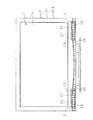
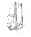
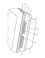
以下本発明をその実施の形態を示す図面に基づいて詳述する。図1は本発明に係る表示装置の構成を示す正面図、図2は要部の構成を示す縦断側面図、図3は要部の構成を示す背面側斜視図、図4は要部の構成を示す正面の底側斜視図、図5はキャビネットの一部を省略した背面側斜視図である。 Hereinafter, the present invention will be described in detail with reference to the drawings illustrating embodiments thereof. 1 is a front view showing the configuration of a display device according to the present invention, FIG. 2 is a longitudinal side view showing the configuration of the main part, FIG. 3 is a rear side perspective view showing the configuration of the main part, and FIG. 4 is the configuration of the main part. FIG. 5 is a rear perspective view in which a part of the cabinet is omitted.
図示した表示装置はテレビ画像等を表示する表示面1aを前側に有し、略直方形をなす表示部1と、該表示部1の下部両側に装着され、音波を前方へ放射するスピーカ2と、表示面1aに対応する箇所が開放され、表示部1及びスピーカ2を被覆するキャビネット3とを備える薄型の液晶テレビである。
The illustrated display device has a display surface 1a for displaying a television image or the like on the front side, a
表示部1は前側に表示面1aを有する液晶のパネル11と、該パネル11の後側に配置された光学シート12と、バックライト部13と、電源基板等のテレビ基板とを備える。
The
スピーカ2は、低音用の音源21及び中・高音用の音源22と、夫々の音源21,22を横に並べて保持し、音源21が発生した低音の音波、及び音源22が発生した中・高音の音波を前方へ放射する音波放射部を有する保持ケース23とを備え、該保持ケース23がキャビネット3の下部内側に取着されている。
The
キャビネット3は、表示部1の前側周縁部及びスピーカ2の前部を被覆する前キャビネット本体31と、表示部1及びスピーカ2の周縁部より後側を被覆する後キャビネット本体32とを備え、後キャビネット本体32の前端部を前キャビネット本体31の後端部内側に重合させた状態で互いに取外し可能に連結されている。
The
前キャビネット本体31は表示部1の前側周縁部を被覆する矩形の枠部31aと、該枠部31aの下部に連なり、横方向の両端部に複数の第1の放音孔33を有するスピーカ支持部31bとを有し、該スピーカ支持部31bの後面で、第1の放音孔33に対応する箇所(両端側)に、二つのスピーカ2,2が取付けられる座部31cが設けられており、夫々の座部31cにスピーカ2,2の保持ケース23がビスにより取外しを可能に取着されている。
The
スピーカ支持部31bは、横長の矩形をなし、横方向の両端部に前後に貫通する第1の放音孔33が開設されている放音板部31dと、該放音板部31dより前側でスピーカ2の上部、換言するとスピーカ2の表示部1側部分を隠蔽し、枠部31aに連なる非孔壁部31eと、該非孔壁部31eの下縁及び放音板部31dの上縁に前後で連なり、横長の矩形をなす連壁板部31fとを有し、該連壁板部31fの長手方向両端部で、第1の放音孔33に臨む箇所に、上下に貫通する複数の第2の放音孔34を開設してある。
The
前キャビネット本体31の内側で、非孔壁部31eと枠部31aとの間には、スピーカ2の前面上部と僅少の間隔で対向する横板状の遮音壁31gが設けられ、非孔壁部31eの内側を、スピーカ2の前面と放音板部31dとの間の放射音室31hに連通する低音の音波通路31iとしてある。また、放音板部31dの前側には複数の細孔を有する装飾板35が取付けられている。
Inside the
後キャビネット本体32は、後壁32a及び該後壁32aの周縁に連なる二つの側壁、天壁及び底壁32bを有する正面視矩形の深皿形をなしている。
The rear cabinet
以上のように構成された表示装置はスピーカ支持部31bの横方向両端部の座部31cに取着されているスピーカ2は上部を除く下側の前面が図2のように放音板部31dの第1の放音孔33と対向する位置にあり、スピーカ2の上部の前面が非孔壁部31eと対向する位置にあり、スピーカ2の全体が表示部1側に寄せて配置されている。従って、表示面1aからスピーカ2側下縁までの長さを短縮することができ、表示装置を小形にできる。また、表示面1aからスピーカ2側下縁までの長さを短縮できるため、図1のように正面視でのデザイン性を高めることができる。
In the display device configured as described above, the
スピーカ2の中・高音用の音源22から放射された中・高音の音波は指向性があるため、スピーカ2前方の第1の放音孔33から前方へ放音することができ、また、低音用の音源21から放射された低音の音波は指向性がないため、スピーカ2前方の放射音室31hから低音の音波通路31iを経て第2の放音孔34から下方へ放音することができる。このように低音の音波を第1の放音孔33と別個の第2の放音孔34からキャビネット3の前方へ放音するため、非孔壁部31eの内側を音波の通路にでき、音波のキャビネット3内での放音抵抗を低減でき、良好な音質を得ることができる。
The middle / high sound wave radiated from the
尚、以上説明した実施の形態では表示部1の下側にスピーカ2が装着されている構成について説明したが、その他、スピーカ2は表示部1の両側部、一側部又は上部に装着されている構成であってもよく、略直方形をなす表示部1のいずれか一辺側に装着される構成であればよい。この場合、スピーカ2部分は図2に示す断面構造と同様になる。例えば、表示部1の両側部にスピーカ2が装着される場合、第1の放音孔33は前後に開設され、第2の放音孔34は横方向に開設、換言すると表示面1aに沿う方向に開設される。
In the embodiment described above, the configuration in which the
また、以上説明した実施の形態では表示部1の下部両側にスピーカ2,2を装着してなる表示装置について説明したが、その他、スピーカ2は表示部1の下部一側、下部中央部等の一箇所に備える構成としてもよい。
In the above-described embodiment, the display device in which the
また、本発明に係る表示装置は液晶テレビ等の液晶表示装置である他、プラズマ表示装置、ELディスプレィ等の表示装置であってもよい。 In addition to the liquid crystal display device such as a liquid crystal television, the display device according to the present invention may be a display device such as a plasma display device or an EL display.
1 表示部
1a 表示面
2 スピーカ
3 キャビネット
33 第1の放音孔
34 第2の放音孔
31e 非孔壁部
31f 連壁板部(連壁部)
DESCRIPTION OF
Claims (1)
Priority Applications (1)
| Application Number | Priority Date | Filing Date | Title |
|---|---|---|---|
| JP2006263298A JP4606397B2 (en) | 2006-09-27 | 2006-09-27 | Display device |
Applications Claiming Priority (1)
| Application Number | Priority Date | Filing Date | Title |
|---|---|---|---|
| JP2006263298A JP4606397B2 (en) | 2006-09-27 | 2006-09-27 | Display device |
Publications (2)
| Publication Number | Publication Date |
|---|---|
| JP2008085661A JP2008085661A (en) | 2008-04-10 |
| JP4606397B2 true JP4606397B2 (en) | 2011-01-05 |
Family
ID=39356057
Family Applications (1)
| Application Number | Title | Priority Date | Filing Date |
|---|---|---|---|
| JP2006263298A Expired - Fee Related JP4606397B2 (en) | 2006-09-27 | 2006-09-27 | Display device |
Country Status (1)
| Country | Link |
|---|---|
| JP (1) | JP4606397B2 (en) |
Families Citing this family (2)
| Publication number | Priority date | Publication date | Assignee | Title |
|---|---|---|---|---|
| JP6010013B2 (en) * | 2013-12-05 | 2016-10-19 | 株式会社東芝 | Display device |
| JP2018129685A (en) * | 2017-02-08 | 2018-08-16 | シャープ株式会社 | Display unit and television receiver |
Family Cites Families (4)
| Publication number | Priority date | Publication date | Assignee | Title |
|---|---|---|---|---|
| JPH01261099A (en) * | 1988-04-12 | 1989-10-18 | Matsushita Electric Ind Co Ltd | Speaker mounting device |
| JPH06217387A (en) * | 1993-01-20 | 1994-08-05 | Sony Corp | Speaker for television receiver |
| JPH0759184A (en) * | 1993-03-05 | 1995-03-03 | Matsushita Electric Ind Co Ltd | Housing, audio / visual equipment and manufacturing method thereof |
| JP3351012B2 (en) * | 1993-04-12 | 2002-11-25 | 松下電器産業株式会社 | Speaker device |
-
2006
- 2006-09-27 JP JP2006263298A patent/JP4606397B2/en not_active Expired - Fee Related
Also Published As
| Publication number | Publication date |
|---|---|
| JP2008085661A (en) | 2008-04-10 |
Similar Documents
| Publication | Publication Date | Title |
|---|---|---|
| US11314476B2 (en) | Display apparatus | |
| US8351631B2 (en) | Bass sound amplifying enclosure, woofer including the same, and electronic device including the woofer | |
| US8477966B2 (en) | In-wall sub-woofer with high-volume displacement | |
| US20160105740A1 (en) | Sound output apparatus, sound output method and image display apparatus | |
| JP2010256607A (en) | Image display | |
| JP2010239249A (en) | Display device | |
| JP2022141753A (en) | Display device | |
| JP2009267577A (en) | Thin display device | |
| JP5166973B2 (en) | Speaker device and driving method thereof | |
| EP3908008B1 (en) | Display device and speaker | |
| JP2008005459A (en) | Display device | |
| JP4606397B2 (en) | Display device | |
| JP5215797B2 (en) | Building panel with speaker function | |
| JP2014206644A (en) | Display device | |
| JP2017021160A (en) | Video display device attachment apparatus and video display device attachment structure | |
| CN101690185A (en) | Display device and speaker system for the display device | |
| JP4897785B2 (en) | Composite speaker device | |
| JP2010276858A (en) | Display device | |
| US20200196051A1 (en) | Loudspeaker and electronic apparatus including the same | |
| JP5113790B2 (en) | Building panel with speaker function | |
| JP6579891B2 (en) | Display device and television receiver | |
| JP5090893B2 (en) | Panel for display device installation | |
| JP5659326B1 (en) | Music box device | |
| JP2004048168A (en) | Mount with speaker | |
| CN111193986A (en) | Display device |
Legal Events
| Date | Code | Title | Description |
|---|---|---|---|
| A621 | Written request for application examination |
Free format text: JAPANESE INTERMEDIATE CODE: A621 Effective date: 20080806 |
|
| A977 | Report on retrieval |
Free format text: JAPANESE INTERMEDIATE CODE: A971007 Effective date: 20100518 |
|
| A131 | Notification of reasons for refusal |
Free format text: JAPANESE INTERMEDIATE CODE: A131 Effective date: 20100629 |
|
| A521 | Request for written amendment filed |
Free format text: JAPANESE INTERMEDIATE CODE: A523 Effective date: 20100823 |
|
| TRDD | Decision of grant or rejection written | ||
| A01 | Written decision to grant a patent or to grant a registration (utility model) |
Free format text: JAPANESE INTERMEDIATE CODE: A01 Effective date: 20101005 |
|
| A01 | Written decision to grant a patent or to grant a registration (utility model) |
Free format text: JAPANESE INTERMEDIATE CODE: A01 |
|
| A61 | First payment of annual fees (during grant procedure) |
Free format text: JAPANESE INTERMEDIATE CODE: A61 Effective date: 20101005 |
|
| R150 | Certificate of patent or registration of utility model |
Free format text: JAPANESE INTERMEDIATE CODE: R150 |
|
| FPAY | Renewal fee payment (event date is renewal date of database) |
Free format text: PAYMENT UNTIL: 20131015 Year of fee payment: 3 |
|
| LAPS | Cancellation because of no payment of annual fees |