JP4605960B2 - Vertical unit for electric drills and electric drill drivers - Google Patents
Vertical unit for electric drills and electric drill drivers Download PDFInfo
- Publication number
- JP4605960B2 JP4605960B2 JP2001340032A JP2001340032A JP4605960B2 JP 4605960 B2 JP4605960 B2 JP 4605960B2 JP 2001340032 A JP2001340032 A JP 2001340032A JP 2001340032 A JP2001340032 A JP 2001340032A JP 4605960 B2 JP4605960 B2 JP 4605960B2
- Authority
- JP
- Japan
- Prior art keywords
- drill
- guide
- rotating plate
- vertical
- electric
- Prior art date
- Legal status (The legal status is an assumption and is not a legal conclusion. Google has not performed a legal analysis and makes no representation as to the accuracy of the status listed.)
- Expired - Fee Related
Links
Images


Landscapes
- Drilling And Boring (AREA)
Description
【0001】
【発明の属する技術分野】
本発明は、小型、軽量で容易に加工面に対してドリルを垂直状態に保持して作業を行うことができる電動ドリル用及び電動ドリルドライバー用の垂直器に関する。
【0002】
【従来の技術】
加工面に対して、垂直に穴あけを行うことは、非常に熟練のいるものであり、特に初心者においては、思い通りに穴あけができないことも多く、加工面に対して垂直に穴あけを簡単に行うための電動ドリル用の垂直器が各種使用されている。
【0003】
電動ドリルに水準器を取付けて、その水準器を確認しながら、加工面に対して垂直あるいは水平に穴あけ作業などを行うことができるようにしたものもある。例えば、実開平6−66904号では、電動ドリルに、そのドリルの軸方向と、該軸方向に直交する方向の水平を視認できる水準器を備えたものである。これらの水準器で加工面に対する垂直度を確認しながら正確に穴あけ作業を行うことができる。
【0004】
また、電動ドリルを垂直に固定して上下動させる簡易スタンドなども使用されている。例えば、実開平5−9811号では、当て板の上に支持軸を立設し、その支持軸にスプリングで上下動する支持筒を取り付け、この支持筒に電動ドリルを固定したものであり、支持筒とドリルが平行に上下動するように、支持筒の上部に突起を設け、この突起に係合する係合溝を電動ドリルの周面に刻設したものである。
【0005】
当て板を加工面に当接し、支持筒に取付けた電動ドリルを押し下げ、ドリルの先端が加工面に当接した時点でスイッチをいれ、電動ドリルを押し下げながら穴あけ作業を行うことで、加工面に垂直に穴をあけることができるものである。
【0006】
【発明が解決しようとする課題】
このように、電動ドリル用の垂直器は各種開発されているが、小型、軽量で、持ち運びに便利でどこへでも持っていって使用できることが望まれている。また、使用状態においては、加工面が作業しやすい床面だけではなく、垂直な壁面であったり、傾斜した面であったり、天井面であったりする場合にも対応できることが必要である。
【0007】
上記の実開平6−66904号では、水準器により加工面に対してドリルを垂直に保持して穴開けを行うことはできるが、この場合にはあくまでも、加工面が水平あるいは垂直である場合にのみその加工面に対して垂直に穴を開けることができるというものであり、穴をあける材料を水平に置いた場合や、床面あるいは、垂直な壁面などには有効であるが、加工面が傾斜している場合には、使用できない。
【0008】
また、上記の実開平5−9811号の場合には、支持軸とドリル軸とが同一軸線となっておらず、当て板が加工面に対して平行にセットされたとしても、当て板と支持軸との誤差、支持筒への電動ドリルの取り付け金具の誤差、取り付け金具と電ドリルとの誤差など、多くの誤差を生じる可能性がある。
【0009】
さらに、支持筒は、当て板の端部に取り付けられるため、当て板を加工面に正確に水平に当接されているかどうかを見分けることは難しく、電動ドリルを上下動する際に、当て板が傾斜してしまう可能性もある。このため、精度を高めるためには、当て板を大きくしなければならない。
【0010】
また、電動ドリルを用いて、ビス止め作業などを行うことも多いが、上記のような電動ドリル用の垂直器においては、ビスを手で押さえ、ドライバードリルの先をビスの頭部に当てて作業することとなり、不慣れな場合には、ドリルの回転と同時にビスの軸心がずれてビスが曲がってねじ込まれてしまうことも多い。
【0011】
本発明は、上記のような問題点に鑑みてなされたものであり、小型、軽量であり、加工面が傾斜した面においても、ドリルやビスを正確に該加工面に対して垂直に保持でき、狭い場所や姿勢の悪い場所においても容易に作業が行える、作業性が良く、信頼性の高い電動ドリル・電動ドリルドライバー用垂直器を提供することを課題とする。
【0012】
【課題を解決するための手段】
本発明は、前記に示す課題を解決するために、電動ドリルのドリルチャックに固定するための固定手段が設けられたコイルバネと、該コイルバネの先端部に、ドリルを加工面に垂直にスライド支持するための垂直ガイドが設けられ、該垂直ガイドは、加工面に対して平行に当接する円板状の回転板と、該回転板の軸心部に垂直に設けられた、円筒状ドリルガイドとから構成した電動ドリル用垂直器としたものである。
【0013】
該コイルバネは、金属線を螺旋状に巻いたバネであり、軽い押圧力で伸縮するものであれば何れでも良く、その一端に電動ドリルのドリルチャックに固定するための固定手段が設けられたものである。該固定手段は、ドリルチャックに固定できるものであればいずれでも良く、例えば、コイルバネの先端にビス止めが設けられたリングを取り付け、該リングをドリルチャックに被せて、ビスで固定できるようにしたものでも良い。
【0014】
該回転板は、平坦で一定の厚さを有する剛性の円板であり、その軸心部に円筒状ドリルガイドが設けられたものである。平坦で歪み難く、軽量な円板であることが望ましく、薄い金属板や厚板の硬質樹脂板などでも良い。また、回転板の底面は、加工面との摩擦力を軽減するために、樹脂シートや潤滑塗装などの被覆処理されたものでも良い。
【0015】
該円筒状ドリルガイドは、回転板に対して垂直に設けられた円筒状部材であり、該円筒内部にドリルが挿通し、ドリルを円板に対して垂直に保持して上下動できるようにしたものである。ドリルの径に合わせた金属製パイプなどでも良い。
【0016】
また、本発明では、前記の垂直ガイドにおいて、円筒状ドリルガイドが着脱構造となっており、該円筒状ドリルガイドを取り換えて使用できるようにしたものである。該円筒状ドリルガイドは着脱できる構造であればいずれでも良く、例えば、前記のコイルバネとの接続部にリング部材を設け、該リング部材と前記の回転板とで上下から円筒状ドリルガイドを挟み込んで固定し、リング部材と回転板とを嵌め合わせやビス止めなどで連結接合できるようにしたものでも良い。
【0017】
また、本発明では、前記の回転板において、加工面との当接面側に、複数の突起を設けたものである。該突起は、回転板が加工面との摩擦力を軽減するために設けられるものであり、回転板の底面が加工面に接触しない程度に突出しておれば良く、突端は球面状となっているものが好ましく、例えば、金属球や硬質樹脂球を複数個、固着したものでも良い。また、突起部と加工面との間に潤滑カバーを設けて回転板がスムースに回転できるようにしても良い。さらに、切りくずが潤滑カバーと回転板の隙間に入り込まないように、回転板の上部全面を覆う円板状のカバーを設けても良い。
【0018】
また、本発明では、前記の回転板において、加工面との当接面側に、回転板の回転方向に走行自在な複数の車輪を設けたものである。
【0019】
該車輪は、回転方向に正逆双方に走行できるものであればいずれでも良く、同一円周上に3台以上設けることが好ましい。例えば、ドリル径より大きなリング部材の外周に車輪の回転軸を放射状に取り付け、回転板の底面に設けた車輪軸受に車輪を軸支させたものなどでも良い。
【0020】
また、本発明では、前記の回転板において、その中心側と外周側とを互いに回動自在に連結し、外周側の底面を中心側より突出させ、加工面に対して外周側が当接するようにしたものである。
【0021】
該回転板の中心側と外周側との回動手段は、回動自在であれば何れでもよいが、ころがり軸受などが好ましい。該ころがり軸受は、ボールベアリングやローラーベアリングなどを用いることができる。
【0022】
回転板の外周側の底面が中心側より突出していることにより、外周側が加工面に当接して固定され、中心側が回動自在となる。外周側の底面は、滑り止め処理されていても良い。
【0023】
また、本発明では、前記の円筒状ドリルガイドにおいて、前記の回転板の軸心部に垂直に設けられた円筒状ガイド部と、その下部にビスを誘導するための円筒状の誘導部が設けられており、該ビス誘導部には、その側面にビス挿入口と、バネ材からなるパイプの下部が絞られ、切れ込みにより先端が尖った形状となった誘導支持筒とが設けられているもので、ドライバードリルを用いた場合のビス止め用の円筒状ドライバーガイドである。
【0024】
該ビス挿入口は、円筒状の誘導部の側面に設けられ、ビスを挿入できる開口部である。また、誘導支持筒は、その先端部が内部からバネ力に抗して押し開かれる構造となったものであり、前記のビス挿入口よりビスが挿入され、この誘導支持筒内に差し込まれ、ドライバードリルにより上部から押圧され、該誘導支持筒の先端部を押し開いて送り出され、加工面に略垂直にセットでき、ビスを垂直にねじ込むことができるようにしたものである。
【0025】
【発明の実施の形態】
以下に、本発明による実施の形態を図面を用いて説明する。
【0026】
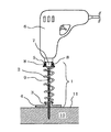
図1は、本発明による電動ドリル用垂直器の一実施例を示す概略図であり、電動ドリルに装着し、板材に対して垂直に穴あけ加工を行う状態を示したものである。
【0027】
この電動ドリル用垂直器1は、コイルバネ2と、垂直ガイド3が一体化された回転板4が設けられている。該コイルバネ2の上部には、取り付けリング5が設けられており、電動ドリル6のドリルチャック7にビス8で固定されている。
【0028】
該垂直ガイド3は、回転板4に垂直に開けられた軸心穴にドリル9が挿通されている。穴あけ作業に際しては、穴あけ部材10の加工面11上に電動ドリル用垂直器1の回転板4を平坦に当てて、電動ドリル6を押し下げ、コイルバネ2を収縮させて、ドリル9の先端を加工面11に当て、この状態で電動ドリル6のスイッチを入れる。
【0029】
ドリル9が回転するとともに、ドリルチャック7に取付けられた電動ドリル用垂直器1全体が回転する。さらに電動ドリル6を押し下げることにより、コイルバネ2が収縮し、ドリル9が垂直ガイド3に垂直に支持された状態で穴あけを行うことができる。
【0030】
該コイルバネ2は、上部のコイル径が大きく、下部のコイル径が小さくなっており、収縮時には、順次、大きなコイル部の中側に小さなコイル部が収まるようにして収縮する。
【0031】
ドリル9軸線と、電動ドリル用垂直器の軸心とが同一軸心となるため、ドリル9の押し下げ動作により、軸心がずれてドリルが傾く心配はない。また、ドリル9の垂直度の確認は、回転板4の回転状態により容易に視認できる。すなわち、加工面11に回転板4が平行状態であると、回転板4はスムースに回転し、平行状態からずれると、回転状態が不安定となる。
【0032】
穴あけが完了し、スイッチをオフとし、電動ドリル6の押圧力を緩めると、コイルバネの復元力により伸張して、ドリル9は、元の状態に回復する。
【0033】
特開平5−9811号などに示すドリルスタンドのように、ドリルの垂直度を高めるために、当て板を大きくする必要はないので、回転板4は、電動ドリル6本体よりも小さくでき、狭い場所でも使用できる。また、電動ドリル用垂直器1全体の重量も、1kg以下となり、非常に軽量であるため、天井部への穴あけ作業など、作業条件の悪い場所での穴あけ作業も楽に行うことができる。
【0034】
また、ドリル9に磁石製の小さなコイルを被せてドリルチャック7に磁着させておくと、電動ドリル6を押し下げ過ぎてドリルチャック7が垂直ガイド3の頭部に当り損傷することを防止できる。
【0035】
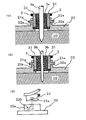
図2は、本発明による電動ドリル用垂直器において、垂直ガイドが着脱構造の円筒状ドリルガイドとした実施例を示す図である。
【0036】
(1)は、径の大きなドリル9a用の円筒状ドリルガイド3aを取付けた例であり、(2)は径の小さなドリル9b用の円筒状ドリルガイド3bを取付けた例である。(3)は、円筒状ドリルガイド3a、3bを取付けた係合リング21を回転板22の係合部22aに取付ける状態を示す図である。
【0037】
コイルバネ2の下端部に係合リング21が設けられており、該係合リング21に鍔付きの円筒状ドリルガイド3a、3bが下部側から嵌め込まれている。この円筒状ドリルガイド3a、3bが嵌め込まれた係合リング21が回転板22に上部より嵌め込まれて固着されるようになっている。
【0038】
(3)に示すように、係合リング21の突起部21aを係合溝22bが設けられた回転板22の係合部22aに嵌め合わせ、及び分離させることにより、円筒状ドリルガイド3a、3bを着脱し、ドリル径に合わせて取り換えることができる。
【0039】
図3は、本発明による電動ドリル用垂直器の他の実施例を示す図であり、回転板の底面に突起が設けられたものであり、(1)は側面図を示し、(2)は底面図を示す。
【0040】
この回転板31は、下面の同一円周上に等間隔に4つの突起32が設けられている。該突起32は、金属製突起を接着剤で強固に接着したものである。該回転板31の係合部31aを前記の係合リング21に嵌め合わせて取付ける。
【0041】
穴あけ時には、回転板31が回転するが、加工部材10の加工面11との接触部が4つの突起32の先端部となるため、摩擦力が軽減され、回転板31の回転がスムースとなる。突起部による加工面の損傷や摩擦力を軽減するために、突起と加工面との間に金属板や樹脂板などによる潤滑カバーを設けても良い。さらに、切りくずが潤滑カバーと回転板との隙間に入り込まないように、回転板の上部全面を覆う円板状の防塵カバーを設けても良い。
【0042】
図4は、本発明による電動ドリル用垂直器のさらに他の実施例を示す図であり、回転板の底面に回転方向に走行する車輪を設けたものである。(1)は、側部断面図であり、(2)は底面図である。
【0043】
該回転板41は、底面の同一円周上の4箇所に軸受42が設けられており、各軸受42に車輪43が位置するように車軸44が軸支され、各車軸44は、リング状の車軸固定台45の外周部に放射状に固定されている。該車軸固定台45は、回転板41の軸心穴41bの径より大きなリング部材となっている。
【0044】
また、該回転板41の底面外周部は、下方に突出する淵部41aが設けられている。該回転板41は、係合部41cを前記の係合リング21にはめ合わせて取付ける。
【0045】
このように、回転板41に車輪43が設けられているため、穴あけ時には、回転板41がスムースに回転し、回転の負荷が軽減され、スムースに穴あけ作業が行える。また、回転板41の外周部には、淵部41aが設けられているため、外部から切りくずが侵入して車輪43の走行が妨げられることはない。
【0046】
図5は、本発明による電動ドリル用垂直器のさらに他の実施例を示す図であり、回転板の中心部と外周部とが互いに回動できる構造となっているものであり、(1)は、その側部断面図であり、(2)は、底面図である。
【0047】
この回転板は、中心部の回転板本体51aと外周部の回転板支持台51bとに分割されており、ボールベアリング51cによるころがり軸受けで連結されている。該回転板支持台51bは、低部に脚部51eが突出しており、加工部材10の加工面11に当接して固定される。
【0048】
該回転板は、その係合部51dにより、前記の係合リング21にはめ合わせて取付けられる。
【0049】
穴あけに際しては、回転板支持台51bの脚部51eを加工面に押し当てて固定し、ドリル9とともに回転板本体51aが回転する。ボールベアリング51cが用いられているため、回転は非常にスムースであり、回転板支持台51bにより、確実に加工面11に当接しており、ドリル9は正確に垂直が保たれて穴あけできる。
【0050】
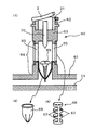
図6は、本発明による電動ドリル用垂直器のドライバードリル用ドライバーガイドの実施例を示すものであり、(1)は、縦断面図を示し、(2)は、誘導支持筒68を示し、(3)は、ビス挿入扉66を示す図である。
【0051】
該ドライバードリル用ドライバーガイド60は、回転板61と一体化されており、上部にコイルバネ2の係合リング21に係合する係合部62が設けられている。
【0052】
該係合部62の下部にドライバーガイド部63が設けられ、その下部にビス誘導部64が設けられ、さらにその下部に回転板61が設けられた構成となっている。
【0053】
該ビス誘導部64は、側壁部にビス挿入口65が設けられ、その外周部に(3)に示すような樹脂製の扉片67を複数設けたビス挿入扉66が嵌め込まれて取付けられており、該ビス挿入口65の下部側には、誘導支持筒68が内設されている。
【0054】
該誘導支持筒68は、(2)に示すように、バネ材からなるパイプの下部側に切れ込みを切設し、先端を絞って尖らせた形状としたものである。
【0055】
このような構成において、電動ドリル6にドライバー70を取り付け、前記のコイルバネ2をドリルチャックに取り付け、コイルバネ2の係合リング21に係合部62にはめ合わせてドライバーガイド60を接合する。
【0056】
次にビス69をビス挿入口65より挿入する。このとき、ビス挿入扉66の扉片67を押し開いてビスを挿入する。扉片67は、ビスの挿入後は、復元し、扉片67は閉まる。ビス69は、誘導支持筒68内部に収まる。
【0057】
ここで電動ドリル6を押し下げると、コイルバネ2が収縮し、ドライバー70がドライバーガイド63を挿通して誘導支持筒68内のビス69の頭部に押し当たる。さらに押し下げ、ビス69は誘導支持筒68の先端を押し広げて下降する。このとき、ビス69は、バネ材の弾性力により、垂直に支持され、その先端が加工面11まで到達する。
【0058】
ここで電動ドリル6のスイッチを入れると、ビス69は垂直に支持された状態で加工部材10にねじ込まれ、容易にビス止め作業を行うことができる。
【0059】
本実施例では、回転板61とドライバーガイド60は一体化されているが、着脱構造としても良い。
【0060】
【発明の効果】
以上、詳細に説明した本発明では、以下に示すような効果がある。
【0061】
1)垂直ガイドをコイルバネと連結してドリルチャックに固定することにより、ガイドとドリルの回転軸を同一軸とすることができ、電動ドリルの上下動による軸ズレがまったくなく、上下動作がスムースであり、ドリルへの負担もなく、ドリルが折れて破損するようなこともなくなる。
【0062】
2)円筒状ドリルガイドと回転板を用いることにより、加工面に対して、簡単、確実にドリルを垂直に保持して穴あけすることができる。
【0063】
3)構造が簡単であり、部材が少なく軽量であり、作業性の悪い場所でも楽に扱える。
【0064】
4)当て板となる回転板は電動ドリルよりも小さくでき、非常に小型であり、狭い場所でも楽に作業できる。
【0065】
5)ドリルガイドを着脱式とすることにより、ドリルのサイズに合わせたドリルガイドを簡単取り換えて使用することができる。
【0066】
6)回転板の底面に複数の突起や車輪を設けることにより、回転板がスムースに回転し、電動ドリルへの負荷を減少できる。
【0067】
7)回転板を中心側と外周側とで互いに回動できる構造とすることにより、回転板の中心を回転させ、外周部を加工面に当接させ固定できるので、より正確に垂直度を保持した状態で穴あけできる。
【0068】
8)ドリルガイドにビス誘導部を設け、誘導支持筒を設けることにより、ドライバードリルを用いて、ビスを垂直に支持した状態で加工面に確実にねじ込むことができる。
【0069】
9)ドリルチャックに着脱できる構造であるため、専用の取り付け器具を必要とせず、ほとんどの電動ドリルドライバーに容易に装着して使用することができる。
【0070】
このように、本発明によれば、小型、軽量であり、加工面が傾斜した面においても、ドリルやビスを正確に該加工面に対して垂直に保持でき、狭い場所や姿勢の悪い場所においても容易に作業が行える、作業性が良く、信頼性の高い電動ドリル用垂直器を実現できる。
【図面の簡単な説明】
【図1】 本発明による電動ドリル用垂直器の実施例を示す図である。
【図2】 本発明による電動ドリル用垂直器のドリルガイドの着脱構造の実施例を示す図である。
【図3】 本発明による電動ドリル用垂直器の突起付き回転板の実施例を示す図である。
【図4】 本発明による電動ドリル用垂直器の車輪付き回転板の実施例を示す図である。
【図5】 本発明による電動ドリル用垂直器の外周部固定式回転板の実施例を示す図である。
【図6】 本発明による電動ドリル用垂直器のドライバードリル用ドライバーガイドの実施例を示す図である。
【符号の説明】
1 電動ドリル用垂直器
3 垂直ガイド
3a、3b 円筒状ドリルガイド
4 回転板
21 係合リング
21a 突起部
22 回転板
22a 係合部
22b 係合溝
31 回転板(突起付き)
32 突起
41 回転板(車輪付き)
41a 淵部
51a 回転板本体
51b 回転板支持台
51c ボールベアリング
51e 脚部
60 ドライバーガイド
61 回転板
62 係合部
63 ドリルガイド部
64 ビス誘導部
65 ビス挿入口
66 ビス挿入扉
67 扉片
68 誘導支持筒
69 ビス
70 ドライバー [0001]
BACKGROUND OF THE INVENTION
The present invention relates to a vertical device for an electric drill and an electric drill driver that is small and lightweight and can be easily operated while holding the drill perpendicular to a machining surface.
[0002]
[Prior art]
Drilling perpendicularly to the machined surface is very skilled. Especially for beginners, it is often impossible to drill as intended, and it is easy to make perpendicularly to the machined surface. Various vertical tools for electric drills are used.
[0003]
There is also a type in which a level is attached to an electric drill, and a drilling operation or the like can be performed vertically or horizontally with respect to the processing surface while checking the level. For example, in Japanese Utility Model Laid-Open No. 6-66904, an electric drill is provided with a level that can visually recognize the axial direction of the drill and the horizontal direction perpendicular to the axial direction. With these levels, drilling can be performed accurately while checking the perpendicularity to the processing surface.
[0004]
In addition, a simple stand that vertically moves an electric drill fixed vertically is also used. For example, in Japanese Utility Model Laid-Open No. 5-9811, a support shaft is erected on a backing plate, a support cylinder that is moved up and down by a spring is attached to the support shaft, and an electric drill is fixed to the support cylinder. A protrusion is provided on the upper portion of the support cylinder so that the cylinder and the drill move up and down in parallel, and an engagement groove that engages with the protrusion is carved on the peripheral surface of the electric drill.
[0005]
Abut the contact plate against the machining surface, push down the electric drill attached to the support cylinder, turn on the switch when the tip of the drill comes into contact with the machining surface, and drill the hole while pushing down the electric drill. A hole can be drilled vertically.
[0006]
[Problems to be solved by the invention]
As described above, various vertical tools for electric drills have been developed, but it is desired that they are small and lightweight, convenient to carry and used anywhere. In use, it is necessary to be able to cope with not only the floor surface on which the work surface is easy to work but also a vertical wall surface, an inclined surface, or a ceiling surface.
[0007]
In the above Japanese Utility Model Laid-Open No. 6-66904, drilling can be performed by holding the drill perpendicular to the machining surface with a level, but in this case, the machining surface is only horizontal or vertical. It is only possible to make a hole perpendicular to the machining surface, and it is effective when the material to be drilled is placed horizontally, on the floor surface or vertical wall surface, etc. Cannot be used when tilted.
[0008]
Further, in the case of the above-mentioned Japanese Utility Model Laid-Open No. 5-9811, even if the support shaft and the drill shaft are not the same axis line and the contact plate is set parallel to the processing surface, the support plate and the support shaft are supported. Many errors may occur, such as an error with the shaft, an error in the mounting bracket of the electric drill on the support cylinder, and an error between the mounting bracket and the electric drill.
[0009]
Furthermore, since the support cylinder is attached to the end of the base plate, it is difficult to distinguish whether the base plate is in contact with the machining surface accurately and horizontally. There is also the possibility of tilting. For this reason, in order to raise precision, you have to enlarge a patch plate.
[0010]
In addition, electric drills are often used to fix screws, but in vertical drills such as those described above, hold the screw with your hand and place the tip of the driver drill against the screw head. If you are unfamiliar with the work, the axis of the screw is often shifted simultaneously with the rotation of the drill, and the screw is bent and screwed in often.
[0011]
The present invention has been made in view of the above-described problems, and is small and lightweight, and can hold a drill and a screw accurately perpendicularly to the machining surface even on a slanted machining surface. It is an object of the present invention to provide an electric drill / electric drill driver vertical device that can easily work in a narrow place or a poor posture, has good workability, and high reliability.
[0012]
[Means for Solving the Problems]
In order to solve the above-described problems, the present invention provides a coil spring provided with a fixing means for fixing to a drill chuck of an electric drill, and a drill is slidably supported at the tip of the coil spring perpendicularly to the processing surface. A vertical guide is provided, and the vertical guide includes a disk-shaped rotating plate that is in contact with the machining surface in parallel, and a cylindrical drill guide that is provided perpendicular to the axial center of the rotating plate. The vertical tool for the electric drill is constructed.
[0013]
The coil spring is a spring in which a metal wire is spirally wound and may be any one that can expand and contract with a light pressing force, and is provided with a fixing means for fixing to a drill chuck of an electric drill at one end thereof. It is. The fixing means may be any means as long as it can be fixed to the drill chuck . For example, a ring provided with a screw stopper is attached to the tip of the coil spring, and the ring is put on the drill chuck so that it can be fixed with a screw. Things can be used.
[0014]
The rotating plate is a flat and rigid disc having a certain thickness, and a cylindrical drill guide is provided on the axial center thereof. A flat disk that is flat and hardly distorted is desirable, and may be a thin metal plate or a thick hard resin plate. Further, the bottom surface of the rotating plate may be coated with a resin sheet or a lubricating coating in order to reduce the frictional force with the processed surface.
[0015]
The cylindrical drill guide is a cylindrical member provided perpendicular to the rotating plate, and the drill is inserted into the cylinder so that the drill can be moved vertically by holding the drill perpendicular to the disc. Is. A metal pipe matched to the diameter of the drill may be used.
[0016]
In the present invention, in the above-mentioned vertical guide, a cylindrical drill guide has a detachable structure, and the cylindrical drill guide can be replaced and used. The cylindrical drill guide may be any structure as long as it is detachable. For example, a ring member is provided at a connection portion with the coil spring, and the cylindrical drill guide is sandwiched from above and below by the ring member and the rotating plate. It is also possible to fix the ring member and the rotating plate so that they can be connected and joined by fitting or screwing.
[0017]
In the present invention, the rotating plate is provided with a plurality of protrusions on the contact surface side with the processing surface. The protrusion is provided to reduce the frictional force between the rotating plate and the processing surface, and it is sufficient that the bottom surface of the rotating plate protrudes so as not to contact the processing surface, and the protruding end has a spherical shape. For example, a plurality of metal spheres or hard resin spheres may be fixed. Further, a lubricating cover may be provided between the protrusion and the processed surface so that the rotating plate can be smoothly rotated. Furthermore, a disc-shaped cover that covers the entire upper surface of the rotating plate may be provided so that chips do not enter the gap between the lubricating cover and the rotating plate.
[0018]
In the present invention, the rotating plate is provided with a plurality of wheels that can run in the rotating direction of the rotating plate on the contact surface side with the processing surface.
[0019]
Any wheel may be used as long as it can travel in both the forward and reverse directions in the rotational direction, and it is preferable to provide three or more wheels on the same circumference. For example, a rotating shaft of a wheel may be radially attached to the outer periphery of a ring member larger than the drill diameter, and a wheel may be supported on a wheel bearing provided on the bottom surface of the rotating plate.
[0020]
Further, in the present invention, in the rotary plate, the center side and the outer peripheral side are rotatably connected to each other so that the bottom surface of the outer peripheral side protrudes from the central side, and the outer peripheral side comes into contact with the processing surface. It is a thing.
[0021]
The rotating means between the center side and the outer peripheral side of the rotating plate may be any as long as it is rotatable, but a rolling bearing or the like is preferable. As the rolling bearing, a ball bearing or a roller bearing can be used.
[0022]
Since the bottom surface on the outer peripheral side of the rotating plate protrudes from the center side, the outer peripheral side comes into contact with the processing surface and is fixed, and the center side is rotatable. The bottom surface on the outer peripheral side may be anti-slip processed.
[0023]
Further, in the present invention, in the cylindrical drill guide, a cylindrical guide portion provided perpendicular to the axial center portion of the rotating plate and a cylindrical guide portion for guiding a screw are provided below the cylindrical guide portion. The screw guide portion is provided with a screw insertion port on the side surface thereof and a guide support cylinder having a shape in which the lower part of the pipe made of a spring material is narrowed and the tip is sharpened by cutting. Thus, it is a cylindrical screwdriver guide for screwing when a screwdriver drill is used.
[0024]
The screw insertion opening is an opening provided on the side surface of the cylindrical guide portion and into which a screw can be inserted. In addition, the guide support cylinder has a structure in which the tip portion is pushed open against the spring force from the inside, a screw is inserted from the screw insertion port, and is inserted into the guide support cylinder. It is pressed from the top by a driver drill, pushes open the tip end portion of the guide support cylinder, and is sent out so that it can be set substantially perpendicular to the processing surface and the screw can be screwed vertically.
[0025]
DETAILED DESCRIPTION OF THE INVENTION
Embodiments of the present invention will be described below with reference to the drawings.
[0026]
FIG. 1 is a schematic view showing an embodiment of a vertical unit for an electric drill according to the present invention, and shows a state in which a drilling process is carried out perpendicularly to a plate material attached to the electric drill.
[0027]
The electric drill
[0028]
In the
[0029]
As the
[0030]
The
[0031]
Since the axis of the
[0032]
When the drilling is completed, the switch is turned off, and the pressing force of the
[0033]
Unlike the drill stand shown in Japanese Patent Laid-Open No. Hei 5-9811 and the like, there is no need to increase the size of the contact plate in order to increase the verticality of the drill. But you can use it. Moreover, since the weight of the electric drill
[0034]
Further, if the
[0035]
FIG. 2 is a view showing an embodiment in which the vertical guide is a cylindrical drill guide having a detachable structure in the vertical tool for an electric drill according to the present invention.
[0036]
(1) is an example in which a
[0037]
An
[0038]
As shown in (3), the cylindrical drill guides 3a and 3b are formed by fitting and separating the
[0039]
FIG. 3 is a view showing another embodiment of the vertical unit for an electric drill according to the present invention, in which a protrusion is provided on the bottom surface of the rotating plate, (1) shows a side view, (2) shows A bottom view is shown.
[0040]
The rotating
[0041]
At the time of drilling, the rotating
[0042]
FIG. 4 is a view showing still another embodiment of the electric drill vertical device according to the present invention, in which wheels that run in the rotation direction are provided on the bottom surface of the rotating plate. (1) is a side sectional view and (2) is a bottom view.
[0043]
The
[0044]
Further, the bottom surface outer peripheral portion of the
[0045]
Thus, since the
[0046]
FIG. 5 is a view showing still another embodiment of the electric drill vertical tool according to the present invention, in which the center portion and the outer peripheral portion of the rotating plate can rotate with respect to each other. (1) Is a side cross-sectional view, and (2) is a bottom view.
[0047]
The rotating plate is divided into a
[0048]
The rotating plate is attached to the engaging
[0049]
At the time of drilling, the
[0050]
FIG. 6 shows an embodiment of a driver guide for a driver drill of a vertical tool for an electric drill according to the present invention, (1) shows a longitudinal sectional view, (2) shows a
[0051]
The driver
[0052]
A
[0053]
The
[0054]
As shown in (2), the
[0055]
Oite to such a configuration, mounting the
[0056]
Next, the
[0057]
Now depressing the
[0058]
Here, when the
[0059]
In this embodiment, the rotating
[0060]
【The invention's effect】
As described above, the present invention described in detail has the following effects.
[0061]
1) By connecting the vertical guide with the coil spring and fixing it to the drill chuck, the rotation axis of the guide and the drill can be made the same axis, there is no shaft misalignment due to the vertical movement of the electric drill, and the vertical movement is smooth There is no burden on the drill, and the drill is not broken and broken.
[0062]
2) By using a cylindrical drill guide and a rotating plate, it is possible to easily and surely hold a drill vertically with respect to the machining surface for drilling.
[0063]
3) The structure is simple, there are few members, it is lightweight, and it can be handled easily even in places with poor workability.
[0064]
4) The rotating plate used as the contact plate can be made smaller than the electric drill, is extremely small, and can be easily operated even in a narrow place.
[0065]
5) By making the drill guide removable, it is possible to easily replace and use the drill guide that matches the size of the drill.
[0066]
6) By providing a plurality of protrusions and wheels on the bottom surface of the rotating plate, the rotating plate rotates smoothly and the load on the electric drill can be reduced.
[0067]
7) Since the rotating plate can be rotated between the center side and the outer peripheral side, the center of the rotating plate can be rotated and the outer peripheral part can be fixed in contact with the processing surface, so that the verticality can be maintained more accurately. Can be drilled in
[0068]
8) By providing the screw guide portion on the drill guide and providing the guide support cylinder, the screw can be reliably screwed into the processing surface while the screw is vertically supported using a driver drill.
[0069]
9) Since it has a structure that can be attached to and detached from the drill chuck, it does not require a dedicated mounting tool, and can be easily mounted and used on most electric drill drivers.
[0070]
As described above, according to the present invention, the drill and the screw can be accurately held perpendicularly to the machining surface even in a small and light surface, and the machining surface is inclined. It is possible to realize a vertical tool for an electric drill that can be easily operated, has good workability, and is highly reliable.
[Brief description of the drawings]
FIG. 1 is a view showing an embodiment of a vertical unit for an electric drill according to the present invention.
FIG. 2 is a view showing an embodiment of a drill guide attaching / detaching structure of a vertical tool for an electric drill according to the present invention.
FIG. 3 is a view showing an embodiment of a rotating plate with projections of a vertical tool for an electric drill according to the present invention.
FIG. 4 is a view showing an embodiment of a wheeled rotary plate of an electric drill vertical device according to the present invention.
FIG. 5 is a view showing an embodiment of an outer peripheral fixed rotary plate of an electric drill vertical device according to the present invention.
FIG. 6 is a view showing an example of a driver guide for a driver drill of a vertical tool for an electric drill according to the present invention.
[Explanation of symbols]
DESCRIPTION OF
32
Claims (6)
Priority Applications (1)
| Application Number | Priority Date | Filing Date | Title |
|---|---|---|---|
| JP2001340032A JP4605960B2 (en) | 2001-09-30 | 2001-09-30 | Vertical unit for electric drills and electric drill drivers |
Applications Claiming Priority (1)
| Application Number | Priority Date | Filing Date | Title |
|---|---|---|---|
| JP2001340032A JP4605960B2 (en) | 2001-09-30 | 2001-09-30 | Vertical unit for electric drills and electric drill drivers |
Publications (3)
| Publication Number | Publication Date |
|---|---|
| JP2003103409A JP2003103409A (en) | 2003-04-08 |
| JP2003103409A5 JP2003103409A5 (en) | 2004-08-05 |
| JP4605960B2 true JP4605960B2 (en) | 2011-01-05 |
Family
ID=19154295
Family Applications (1)
| Application Number | Title | Priority Date | Filing Date |
|---|---|---|---|
| JP2001340032A Expired - Fee Related JP4605960B2 (en) | 2001-09-30 | 2001-09-30 | Vertical unit for electric drills and electric drill drivers |
Country Status (1)
| Country | Link |
|---|---|
| JP (1) | JP4605960B2 (en) |
Cited By (1)
| Publication number | Priority date | Publication date | Assignee | Title |
|---|---|---|---|---|
| KR20220165044A (en) * | 2021-06-07 | 2022-12-14 | 동의대학교 산학협력단 | Hole machining tool |
Families Citing this family (9)
| Publication number | Priority date | Publication date | Assignee | Title |
|---|---|---|---|---|
| US7404696B2 (en) * | 2005-02-18 | 2008-07-29 | Black & Decker Inc. | Drill driver with chuck-mounted drill accessories |
| JP2007030154A (en) * | 2005-07-27 | 2007-02-08 | Takeshi Akimoto | Auxiliary tool such as for drill |
| JP5019169B2 (en) * | 2007-05-11 | 2012-09-05 | 孝文 鶴田 | Electric screwdriver auxiliary tool, its connecting tool and its attachment |
| US8734065B2 (en) | 2010-02-03 | 2014-05-27 | Honda Motor Co., Ltd | Reaming tool |
| DE102016011776B3 (en) * | 2016-10-04 | 2018-04-05 | Iml Instrumenta Mechanik Labor Gmbh | Needle guiding device for a drilling resistance measuring device, drilling resistance measuring device and drilling resistance measuring method for the condition examination of wood |
| CN108098018A (en) * | 2017-12-15 | 2018-06-01 | 东莞市国锐自动化设备科技有限公司 | One kind is portable to attack drilling machine guiding mechanism |
| CN109184807B (en) * | 2018-09-05 | 2021-09-28 | 中国航发动力股份有限公司 | Decomposition method of double-tightness chuck |
| KR102392571B1 (en) * | 2019-01-25 | 2022-04-28 | 주식회사 엘지에너지솔루션 | Bolting Device for Manufacturing Battery Pack |
| JP7520705B2 (en) | 2020-12-17 | 2024-07-23 | 株式会社フジタ | Fixture and method for fixing panels |
Citations (8)
| Publication number | Priority date | Publication date | Assignee | Title |
|---|---|---|---|---|
| JPS5061499U (en) * | 1973-10-01 | 1975-06-05 | ||
| JPS51122887A (en) * | 1975-03-31 | 1976-10-27 | Ota Kogyo Kk | Adaptor for power drill |
| JPS5250379U (en) * | 1975-10-09 | 1977-04-09 | ||
| JPS61159172U (en) * | 1985-03-25 | 1986-10-02 | ||
| JPH01110005U (en) * | 1988-01-12 | 1989-07-25 | ||
| JPH0315007U (en) * | 1989-06-26 | 1991-02-15 | ||
| JPH0371864U (en) * | 1989-11-10 | 1991-07-19 | ||
| JP2002301668A (en) * | 2001-04-06 | 2002-10-15 | Nagano Keizo | Screw holder for screwdriver |
-
2001
- 2001-09-30 JP JP2001340032A patent/JP4605960B2/en not_active Expired - Fee Related
Patent Citations (8)
| Publication number | Priority date | Publication date | Assignee | Title |
|---|---|---|---|---|
| JPS5061499U (en) * | 1973-10-01 | 1975-06-05 | ||
| JPS51122887A (en) * | 1975-03-31 | 1976-10-27 | Ota Kogyo Kk | Adaptor for power drill |
| JPS5250379U (en) * | 1975-10-09 | 1977-04-09 | ||
| JPS61159172U (en) * | 1985-03-25 | 1986-10-02 | ||
| JPH01110005U (en) * | 1988-01-12 | 1989-07-25 | ||
| JPH0315007U (en) * | 1989-06-26 | 1991-02-15 | ||
| JPH0371864U (en) * | 1989-11-10 | 1991-07-19 | ||
| JP2002301668A (en) * | 2001-04-06 | 2002-10-15 | Nagano Keizo | Screw holder for screwdriver |
Cited By (2)
| Publication number | Priority date | Publication date | Assignee | Title |
|---|---|---|---|---|
| KR20220165044A (en) * | 2021-06-07 | 2022-12-14 | 동의대학교 산학협력단 | Hole machining tool |
| KR102525330B1 (en) * | 2021-06-07 | 2023-04-24 | 동의대학교 산학협력단 | Hole machining tool |
Also Published As
| Publication number | Publication date |
|---|---|
| JP2003103409A (en) | 2003-04-08 |
Similar Documents
| Publication | Publication Date | Title |
|---|---|---|
| JP4605960B2 (en) | Vertical unit for electric drills and electric drill drivers | |
| US7913269B2 (en) | Motor and storage disk drive with a chucking mechanism for retaining a data storage disk | |
| JP5041000B2 (en) | Screw tightening device | |
| JP5543452B2 (en) | Apparatus comprising a fastening unit | |
| JP2003103409A5 (en) | ||
| CN101380681A (en) | Drilling machine | |
| US5409329A (en) | Drill guiding device | |
| CN1382079A (en) | Manual tool changing apparatus | |
| US20050047003A1 (en) | Disk device and unbalance correcting method thereof | |
| WO2003085661A1 (en) | Spindle motor | |
| CN213671877U (en) | Turbine shell inboard location presss from both sides tight frock | |
| JP2886326B2 (en) | Whetstone automatic changer | |
| CN216421835U (en) | Tool magazine and lathe | |
| JPH0241884A (en) | Changing device for automatic hand of robot | |
| CN210649476U (en) | Automatic rack for workpiece rotary cutting machine | |
| US6086458A (en) | Drill polishing method and its centering tool | |
| JP5000471B2 (en) | Cutting material positioning fence in tabletop cutting machine | |
| JP2004295962A (en) | Disk device | |
| CN219944984U (en) | Bearing device and processing equipment | |
| JPS58132425A (en) | Screw clamping device | |
| CN217475861U (en) | Bearing dismounting device | |
| CN210615853U (en) | Angle-adjustable tooling for machining hub | |
| CN216576638U (en) | Umbrella-shaped tooling clamp | |
| CN212735150U (en) | Flange end seat turning tool | |
| CN214351100U (en) | Positioning tool for drilling of idler gear |
Legal Events
| Date | Code | Title | Description |
|---|---|---|---|
| RD02 | Notification of acceptance of power of attorney |
Free format text: JAPANESE INTERMEDIATE CODE: A7422 Effective date: 20080911 |
|
| RD05 | Notification of revocation of power of attorney |
Free format text: JAPANESE INTERMEDIATE CODE: A7425 Effective date: 20080911 |
|
| A621 | Written request for application examination |
Free format text: JAPANESE INTERMEDIATE CODE: A621 Effective date: 20080916 |
|
| A521 | Written amendment |
Free format text: JAPANESE INTERMEDIATE CODE: A821 Effective date: 20080911 |
|
| A131 | Notification of reasons for refusal |
Free format text: JAPANESE INTERMEDIATE CODE: A131 Effective date: 20100622 |
|
| A977 | Report on retrieval |
Free format text: JAPANESE INTERMEDIATE CODE: A971007 Effective date: 20100624 |
|
| A521 | Written amendment |
Free format text: JAPANESE INTERMEDIATE CODE: A523 Effective date: 20100819 |
|
| TRDD | Decision of grant or rejection written | ||
| A01 | Written decision to grant a patent or to grant a registration (utility model) |
Free format text: JAPANESE INTERMEDIATE CODE: A01 Effective date: 20100914 |
|
| A01 | Written decision to grant a patent or to grant a registration (utility model) |
Free format text: JAPANESE INTERMEDIATE CODE: A01 |
|
| A61 | First payment of annual fees (during grant procedure) |
Free format text: JAPANESE INTERMEDIATE CODE: A61 Effective date: 20101005 |
|
| R150 | Certificate of patent or registration of utility model |
Free format text: JAPANESE INTERMEDIATE CODE: R150 |
|
| FPAY | Renewal fee payment (event date is renewal date of database) |
Free format text: PAYMENT UNTIL: 20131015 Year of fee payment: 3 |
|
| R250 | Receipt of annual fees |
Free format text: JAPANESE INTERMEDIATE CODE: R250 |
|
| R250 | Receipt of annual fees |
Free format text: JAPANESE INTERMEDIATE CODE: R250 |
|
| LAPS | Cancellation because of no payment of annual fees |