JP4604350B2 - Recording medium receiving apparatus and printer having the receiving apparatus - Google Patents
Recording medium receiving apparatus and printer having the receiving apparatus Download PDFInfo
- Publication number
- JP4604350B2 JP4604350B2 JP2000404659A JP2000404659A JP4604350B2 JP 4604350 B2 JP4604350 B2 JP 4604350B2 JP 2000404659 A JP2000404659 A JP 2000404659A JP 2000404659 A JP2000404659 A JP 2000404659A JP 4604350 B2 JP4604350 B2 JP 4604350B2
- Authority
- JP
- Japan
- Prior art keywords
- printer
- hook
- shaft
- shafts
- receiving device
- Prior art date
- Legal status (The legal status is an assumption and is not a legal conclusion. Google has not performed a legal analysis and makes no representation as to the accuracy of the status listed.)
- Expired - Fee Related
Links
Images


Classifications
-
- B—PERFORMING OPERATIONS; TRANSPORTING
- B65—CONVEYING; PACKING; STORING; HANDLING THIN OR FILAMENTARY MATERIAL
- B65H—HANDLING THIN OR FILAMENTARY MATERIAL, e.g. SHEETS, WEBS, CABLES
- B65H2701/00—Handled material; Storage means
- B65H2701/10—Handled articles or webs
- B65H2701/11—Dimensional aspect of article or web
- B65H2701/113—Size
- B65H2701/1131—Size of sheets
- B65H2701/11312—Size of sheets large formats, i.e. above A3
Description
【0001】
【発明の属する技術分野】
本発明は、排出される記録媒体を受ける受け装置及びその受け装置を備えたプリンタに関する。
【0002】
【従来の技術】
プリンタには、比較的大型のサイズの記録媒体、例えばJIS規格のA1判やJIS規格のB1判の幅の印刷用のロール紙に印刷できる大型のプリンタがある。このような大型のプリンタの場合、印刷が完了したロール紙は、通常はプリンタ本体の下方に配設された排紙受け装置により受け取られるようになっている。この排紙受け装置は、比較的短い長さで切断されるロール紙の場合は積み重ねが可能であるのでプリンタの後方側にて受け取り、比較的長い長さで切断されるロール紙の場合は即座に取り出せるようにプリンタの前方側にて受け取るように構成されている。
【0003】
【発明が解決しようとする課題】
上述した従来の排紙受け装置は、比較的大型のサイズのロール紙に対応するため、プリンタ本体の前後に飛び出た形で配設されている。このため、プリンタを移動させる際に邪魔になるので、プリンタ運搬時には排紙受け装置をプリンタから取り外す必要があり、手間が掛かっている。また、本来であれば積み重ねが可能であるので後方側にて受け取るべきサイズのロール紙、例えばB1縦以上B0ノビサイズ以下のロール紙は、排紙受け装置の後方側に余裕がないために前方側で受け取っており、印刷枚数が多くなると取り出しに手間が掛かるようになる。
【0004】
本発明は、上記のような種々の課題に鑑みなされたものであり、その目的は、運搬時や記録媒体の排出時等における使用態様を容易に変更することができる記録媒体の受け装置及びその受け装置を備えたプリンタを提供することにある。
【0005】
【課題を解決するための手段】
上記目的達成のため、本発明の請求項に係るプリンタでは、排出される記録媒体を受ける受け装置を備えたプリンタにおいて、前記受け装置は、矩形状に形成された柔軟性を有するシート部材と、記録媒体の排出方向における前記シート部材の両端部、及びその中間部を係留する複数のシャフトと、任意の位置に配置可能であって、前記シャフトの端部を係止可能な複数の係止部材と、を備え、前記シャフトのうち、前記シート部材の中間部を係留するシャフトは、所定間隔をあけて平行に配置された長さの異なる2本のシャフトと、前記2本のシャフトを一体に固定保持する接続部材と、を備え、前記2本のシャフトのうち、長さが短いシャフトの両端部は、前記接続部材に固定され、長さが長いシャフトの両端部は、前記接続部材を貫通して前記係止部材に回転可能に支持されることを特徴としている。
【0006】
これにより、垂れ落ちているシート部材の一部を、巻き取りのずれを防止しながらシャフトとシャフトの周りに容易に巻き取ることができる。その結果、排紙受け装置の使用態様の変更を容易に行うことができる。
【0007】
また、本発明の請求項に係るプリンタでは、前記長さが長いシャフトの両端部には、抜け防止キャップが取り付けられていることを特徴としている。これにより、巻き取りの際、シート部材がシャフトから抜けることを防止することができる。
【0008】
また、本発明の請求項に係る受け装置では、前記係止部材は、係止している前記各シャフトの軸が平行となるように配設されていることを特徴としている。これにより、記録媒体に皺等を付けずに受けることができる受け部の形状にすることができ、記録媒体の品質を高品質に維持することができる。
【0009】
上記目的達成のため、本発明の請求項に係るプリンタでは、記録媒体の供給部、記録部、排出部、脚部がこの順で上部から配設されており、供給され記録され排出される記録媒体を受ける受け装置を備えたプリンタにおいて、前記受け装置は、矩形状に形成され、両端部及びその中間部が複数のシャフトにそれぞれ沿って係留された柔軟性を有するシート部材と、前記脚部に取り付けられて任意の位置に配置可能であって、前記各シャフトの端部を係止可能な係止部材とを備え、当該係止部材は、装置上部前方に設けられ、装置前方に高さを変えずに移動させて任意の位置に配置することが可能な前部上フックと、当該前部上フックの下方に設けられた前部下フックと、当該前部下フックからみて後方に設けられた後部フックとを有し、前記係止部材の前記前部上フック、前記前部下フック、及び前記後部フックの配置形態、及び当該配置形態における前記シート部材の係止形態で、当該シート部材自体の形態を変化させることにより使用態様を変更することが可能なことを特徴としている。
【0010】
これにより、係止部材を所望の位置に配置してシャフトを持って所望の係止部材に掛け、シート部材を折り畳み、折り曲げ、あるいは伸ばして所望の記録媒体の受け部を形成すことができるので、使用態様の変更作業を簡易に行うことができ、さらに、例えばプリンタの運搬作業のときに邪魔になることはなく、また所定のサイズの記録媒体の取り出し作業をプリンタの前面側から容易に行うことができるようになる。
【0011】
また、本発明の請求項に係るプリンタでは、前記係止部材は、係止している前記各シャフトの軸が平行となるように配設されていることを特徴としている。これにより、記録媒体に皺等を付けずに受けることができる受け部の形状にすることができ、記録媒体の品質を高品質に維持することができる。
【0012】
【発明の実施の形態】
以下、図面に基づいて本発明の実施の形態について詳細に説明する。
【0013】
図1は、本発明の実施の形態に係るプリンタの構成例を示す斜視図であり、図2は、そのプリンタの主要部の内部構成例を示す斜視図である。図1及び図2に示すプリンタ100は、例えばJIS規格のA1判やJIS規格のB1判といった比較的大型のサイズの印刷用紙にまで印刷できる大型のインクジェット式プリンタであり、給紙部110、印刷部120、排紙部130、脚部140がこの順で上部から配設された構成となっている。給紙部110は一体化された印刷部120と排紙部130に対して分離可能に構成されており、これらはプリンタ本体として構成されている。そして、このプリンタ本体は脚部140に対して分離可能に構成されている。
【0014】
給紙部110は、図1に示すように、印刷部120の上部後方に突き出るように設けられている。そして、給紙部110の内部には、図2に示すように、2本のロール紙(印刷用紙)がセット可能なロール紙ホルダ111が斜め上下に設けられ、給紙部110の前面には、図1及び図2に示すように、跳ね上げ式の開閉可能なロール紙カバー112がロール紙ホルダ111を覆うように取り付けられている。
【0015】
ロール紙ホルダ111は、図2に示すように、ロール紙を保持するスピンドル113と、給紙部110の両側壁内面に取り付けられて、スピンドル113の着脱及び懸架が可能な一対のスピンドル受け114、115を備えている。そして、スピンドル113は、中央にロール紙が装着された後、両端がスピンドル受け114、115に装着され、回転可能に軸支持されるようになっている。ロール紙カバー112は、図1及び図2に示すように、上部が回動可能に支持されており、下部を持って持ち上げ、あるいは押し下げることにより開閉するようになっている。
【0016】
印刷部120は、図2に示すように、プリントヘッド121を搭載したキャリッジ122、プリントヘッド121と印刷を実行する為の図示しない制御部とを接続するフレキシブルフラットケーブル(以下、FFCという)123、プリントヘッド121とインクが入った図示しないインクカートリッジとをつなぐインクチューブ124、ロール紙を副走査方向に搬送する図示しない紙送りローラ、ロール紙の浮き上がりを防止する図示しない紙吸引手段等を備えている。そして、印刷部120の上面及び前面には、図1及び図2に示すように、上蓋125及び前蓋126がプリントヘッド121やキャリッジ122等を覆うように取り付けられている。
【0017】
プリントヘッド121は、ブラックインクを吐出するブラックインク用プリントへッドと、イエロー、ライトシアン、シアン、ライトマゼンタ、マゼンタ等の各色のインクを吐出する複数のカラーインク用プリントヘッドとを備えている。そして、プリントヘッド121は、圧力発生室とそれに繋がるノズル開口が設けられており、圧力発生室内にインクを貯留して所定圧で加圧することにより、ノズル開口からロール紙に向けてコントロールされた大きさのインク滴を吐出するようになっている。
【0018】
キャリッジ122は、図2に示すように、主走査方向に設けられているレール127にコロを介して吊り下げられ、キャリッジベルト128に連結されており、図示しないキャリッジ駆動装置によってキャリッジベルト128が作動すると、キャリッジベルト128の動きに連行され、レール127に案内されて往復移動するようになっている。
【0019】
FFC123は、一端が制御部のコネクタに接続され、他端がプリントヘッド121のコネクタに接続されており、印刷信号を制御部からプリントヘッド121に送るようになっている。インクチューブ124は、各色のインク用が配設されており、図示しないインク加圧供給手段を介して各一端が対応する各色のインクカートリッジにつながれ、各他端が対応する各色のプリントヘッド121につながれている。
【0020】
そして、インクチューブ124は、インク加圧供給手段によって加圧された各色のインクをインクカートリッジからプリントヘッド121に送るようになっている。前蓋126は、図1及び図2に示すように、下部が回動可能に支持されており、上部を持って押し下げ、あるいは押し上げることにより開閉するようになっている。
【0021】
排紙部130は、図1及び図2に示すように、ロール紙を副走査方向に搬送する経路の一部を成す排紙ガイド131と、ロール紙を副走査方向に搬送する図示しない排紙ローラを備えている。また、排紙部130の前面側から見て右側には、図1及び図2に示すように、インクカートリッジを収納保持するカートリッジホルダ150が配設されている。
【0022】
脚部140は、図1及び図2に示すように、移動用のコロ141を有する2本の支持柱142と、これらの支持柱142の間に掛け渡されている補強棒(支持柱)143を備えている。そして、支持柱142の上部にプリンタ本体110、120、130が載置されネジ止め固定されるようになっている。
【0023】
このような構成において、インクジェット式プリンタ100を使用する場合は、先ず、給紙部110からロール紙ホルダ111を構成するスピンドル113を取り出し、図3に示すように、スピンドル113に挿入されているロール紙押さえ113aをスピンドル113の一端から引き抜く。
【0024】
そして、図4に示すように、スピンドル113の一端をロール紙Rの軸穴Cの一端から挿入して貫通させ、図5に示すように、ロール紙Rの軸穴Cの一端をスピンドル113の他端側に挿入固定されているロール紙押さえ113bにはめ込んで当接させる。続いて、ロール紙押さえ113aをスピンドル113の一端から挿入して、ロール紙Rの軸穴Cの他端にはめ込む。これにより、ロール紙Rはスピンドル113と共に回転可能となる。
【0025】
次に、図6に示すように、ロール紙Rが挿入されたスピンドル113の両端を持ってインクジェット式プリンタ100の前後方向に対して斜めに向けた状態、すなわちロール紙Rが挿入されたスピンドル113の他端側を一方のスピンドル受け114に向けた状態にする。
【0026】
ここで、このスピンドル受け114は水平方向に回転可能に構成されており、通常はスピンドル113の端部を受ける各スピンドル受け114、115の窪み114a、115aは対向させておくが、ロール紙Rが挿入されたスピンドル113をセットするときは、図7に示すように、一方のスピンドル受け114を回転させて他方のスピンドル受け115に対して約45度の角度を付けておく。
【0027】
その後、ロール紙Rが挿入されたスピンドル113の他端部を一方のスピンドル受け114の窪み114aに掛け、ロール紙Rが挿入されたスピンドル113と共にそのスピンドル受け114を回転させる。そして、各スピンドル受け114、115の窪み114a、115aを対向させて、ロール紙Rが挿入されたスピンドル113の一端部を他方のスピンドル受け115の窪み115aに掛ける。これにより、ロール紙Rが挿入されたスピンドル113を給紙部110に容易にセットすることができる。
【0028】
次に、図8に示すように、ロール紙Rの先端を下方に引き出して印刷部120の搬送経路を通し、さらに図9に示すように、排紙部130の搬送経路まで通す。そして、図10に示すように、ロール紙Rを巻き取り方向に回転させてロール紙Rの先端を例えば排紙ガイド131に形成されているマーカMに位置決めする。その後、インクジェット式プリンタ100を起動して、ロール紙Rを副走査方向に給紙しつつプリントヘッド121を主走査方向に移動させながらインク滴を吐出させ、ロール紙Rに所定の情報を印刷して排紙する。
【0029】
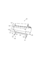
図11及び図12は、本発明の特徴的な部分である記録媒体の受け装置の概略を示す斜視図である。この受け装置400は、図11に示す脚部140の各支持柱142の後部に配設された一対の後部フック部材410、各支持柱142の前部の上部に配設された前部上フック部材420及び各支持柱142の前部の下部に配設された前部下フック部材430と、図12に示す別体とされているシート部材440を備えている。各フック部材410、420、430は、脚部140の中心線に対して対称となるように配設されている。
【0030】
各後部フック部材410は、図21にも示すように、ピン状に形成されて各支持柱142の後部上面にそれぞれ立設されている。各前部上フック部材420は、前部上フック421と、この前部上フック421を保持するフックホルダ425(図14参照)が各支持柱142の前部の上部に対向するようにそれぞれ配設されている。各前部下フック部材430も、前部下フック431と、この前部下フック431を保持するフックホルダ435が各支持柱142の前部の下部に対向するようにそれぞれ配設されている。なお、前部上フック421と前部下フック431は、長さが異なるのみで他の構成は同一である。
【0031】
図13(A)、(B)、(C)は、前部上フック421(前部下フック431)の詳細を示す三面図である。この前部上フック421(前部下フック431)は、ステンレス等の金属で成る棒材422(432)の先端がU字状に曲げられており、後端にプラスチックで成る保持材423(433)がはめ込まれた構成となっている。この保持材423(433)には、後で詳述する案内部423a(433a)及び係止部423b(433b)が突出形成されている。
【0032】
図14は、フックホルダ425の詳細を示す斜視図である。このフックホルダ425は、第1のフックホルダ426と第2のフックホルダ427を備えている。第1のフックホルダ426には、上記保持材423の案内部423aが挿入可能な一端側から他端側に貫通した第1の溝部426aと、この第1の溝部426a内に形成され、上記棒材422がスライド可能にはめ込まれる第2の溝部426bが形成されている。
【0033】
第2のフックホルダ427には、上記保持材423の案内部423aが挿入可能な一端が閉じた溝部427aと、この溝部427aの閉じた端部内に形成され、上記保持材423の係止部423bが着脱される凹部427bが形成されている。そして、第1のフックホルダ426と第2のフックホルダ427は、第1の溝部426aと溝部427aが間隔をあけて連なるように配設されている。
【0034】
このような構成において、各前部上フック部材420の前部上フック421は、図11に示すように、図示矢印a方向、すなわちインクジェット式プリンタ100の前面方向に引き出し・背面方向に押し込み可能になっている。すなわち、前部上フック421がインクジェット式プリンタ100の前面側にて完全に引き出されているときは、図15(A)に示すように、棒材422は第1のフックホルダ426の第2の溝部426bに沿って後端方向へスライドし、保持材423の案内部423aが第1のフックホルダ426の第1の溝部426a内にはまり込んでいる。これにより、前部上フック421は位置決め固定されるようになっている。
【0035】
一方、前部上フック421がインクジェット式プリンタ100の前面側にて完全に押し込まれているときは、図15(B)に示すように、棒材422は第1のフックホルダ426の第2の溝部426bに沿って先端方向へスライドし、保持材423の案内部423aが第2のフックホルダ426の溝部427aに沿って閉じた端部側にスライドして、保持材423の係止部423bが凹部427b内にはまり込んでいる。これにより、前部上フック421は位置決め固定されるようになっている。
【0036】
図16は、フックホルダ435の詳細を示す斜視図である。このフックホルダ435には、一端側から他端側に貫通した第1の溝部435aが形成されている。この第1の溝部435aは、インクジェット式プリンタ100の背面側の一端面から所定距離までは上記保持材423の案内部423aが挿入可能な溝幅に形成されており、そこで溝上面に段差が設けられて溝幅が一旦広げられ、そこからインクジェット式プリンタ100の前面側の他端面に向けて溝幅が徐除に広がるように形成されている。そして、この第1の溝部435a内に揺動可能に形成され、上記棒材422がスライド可能にはめ込まれる第2の溝部435bが形成されている。
【0037】
このような構成において、各前部下フック部材430の前部下フック431は、図11に示すように、図示矢印b方向、すなわちインクジェット式プリンタ100の前面方向に引き出し・背面方向に押し込み可能になっている。すなわち、前部下フック431がインクジェット式プリンタ100の前面側にて完全に引き出されているときは、図17(A)に示すように、棒材432はフックホルダ435の第2の溝部435bに沿って後端方向へスライドし、保持材433の案内部433aがフックホルダ435の第1の溝部435aの一端側を通って第2の溝部435bの一端まで達して、棒材432の自重により第2の溝部435bが下方へ旋回し、保持材433の係止部423bが第1の溝部435a内の段差に突き当てられている。これにより、前部下フック431は位置決め固定されるようになっている。
【0038】
一方、前部下フック431がインクジェット式プリンタ100の前面側に完全に押し込まれているときは、図17(B)に示すように、棒材432は、フックホルダ435の第2の溝部435bに沿って先端方向へスライドして第1の溝部435aの一端側から突き出されていると共に、第1の溝部435aの一端側の溝上面に当接されている。これにより、前部下フック431は位置決め固定されるようになっている。
【0039】
シート部材440は、図12に示すように、布もしくは軟質プラスチックシートで矩形状に形成されており、両端部、その中間部、さらに中間部と一端部の中間部は4本のシャフト441、442、443、444にそれぞれ沿って係留されている。そして、各シャフト441、442、443、444の端部が、後部フック410、前部上フック421、前部下フック431に係止されるようになっている。通常、各シャフト441、442、443、444は、それぞれ平行となるように各フック410、421、431に係止される。
【0040】
以上のような構成の受け装置400は、前部上フック部材420の前部上フック421及び前部下フック部材430の前部下フック431の配置形態、シート部材440の各シャフト441、442、443、444の係止形態及びシート部材440自体の形態を変化させることにより使用態様を変更することが可能となっている。
【0041】
すなわち、前部上フック421及び前部下フック431を所望の位置に配置して任意のシャフト441、442、443、444を持って所望の前部上フック421あるいは前部下フック431に掛け、シート部材440を折り畳み、折り曲げ、あるいは伸ばすことにより、本実施形態では4つのモード、すなわち運搬モード、第1後方排紙(JIS規格のB0サイズ未満)モード、第2後方排紙(JIS規格のB0サイズ以上)モード、前方排紙(長尺紙、厚紙)モードを選択形成すことができる。
【0042】
このようなモードを変更する際の使用者の動作を図18〜図33を参照して説明する。先ず、図18に示すように、各前部上フック部材420の前部上フック421をインクジェット式プリンタ100の背面方向に完全に押し込み、続いて、図19に示すように、各前部下フック部材430の前部下フック431をインクジェット式プリンタ100の背面方向に完全に押し込み、さらに、図20に示すように、各後部フック部材410を脚部140に垂直に差し込む。
【0043】
次に、図21に示すように、シート部材440を一端部のシャフト442がインクジェット式プリンタ100の背面側に位置するように脚部140の下方に広げて、シャフト442の両端部を各後部フック部材410に差し込んで固定する。そして、図22に示すように、各前部上フック421をインクジェット式プリンタ100の前面方向に完全に引き出し、図23に示すように、シャフト443の両端部を各前部上フック421のU字状先端部に掛け、シャフト441の両端部を各前部下フック431のU字状先端部に掛ける。
【0044】
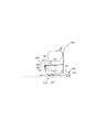
これにより、図24に示すように、シート部材440の一部はインクジェット式プリンタ100の前面側に垂れ落ちた状態になる。続いて、図25に示すように、シャフト443を図示矢印a方向に回転させて垂れ落ちているシート部材440の一部をシャフト443周りに巻き取る。ここで、シャフト443は、図25に示すように、所定間隔をあけて平行に配置された2本のシャフト443a、443bを備えている。一方のシャフト443aの両端は接続部材443cに固定され、他方のシャフト443bの両端は接続部材443cに貫通されて、先端に抜け防止キャップ443dが取り付けられている。
【0045】
このような構成のシャフト443は、シャフト443bの両端部が各前部上フック421のU字状先端部に掛けられ、シャフト443bと共にシャフト443aが図示矢印a方向に回転される。したがって、1本のシャフトのみを回転させる場合と比べて幅広の2本のシャフト443a、443bを回転させる方が容易となり、垂れ落ちているシート部材440の一部をシャフト443bとシャフト443aの周りに容易に巻き取ることができる。さらに、1本のシャフトのみを回転させる場合はシート部材440の巻き取りがずれるおそれがあるが、2本のシャフト443a、443bの場合は一方のシャフト443a側に偏って巻き取られるために、その自重により巻き取りのずれを防止することができる。
【0046】
最後に、図26に示すように、各前部上フック421をインクジェット式プリンタ100の背面方向に完全に押し込む。以上により、各前部上フック部材420と各前部下フック部材430とシート部材440は、プリンタ本体120、130と脚部140の間に完全に収納された状態になり、運搬モードとすることができる。
【0047】
一方、図24に示すように、シート部材440の一部がインクジェット式プリンタ100の前面側に垂れ落ちた状態になったら、図27に示すように、シャフト444の両端部を各前部上フック421のU字状先端部に掛ける。これにより、図28に示すように、各前部上フック421はインクジェット式プリンタ100の前面方向に完全に引き出された状態になっているので、図28及び図29に示すように、シャフト444と排紙部130との間には隙間が生じ、かつシート部材440は後下方に向かって傾斜している。したがって、図29に示すように、排紙部130から排出されるJIS規格のB0サイズ未満のロール紙R1を後方で受ける第1後方排紙モードとすることができる。
【0048】
一方、図24に示すように、シート部材440の一部がインクジェット式プリンタ100の前面側に垂れ落ちた状態になったら、図30に示すように、各前部下フック431をインクジェット式プリンタ100の前面方向に完全に引き出す。これにより、図30及び図31に示すように、各前部上フック421はインクジェット式プリンタ100の前面方向に完全に引き出された状態になっており、さらにインクジェット式プリンタ100の前面側に垂れ落ちていたシート部材440の一部は若干の弛みを持って引き延ばされているので、シャフト444と排紙部130との間には隙間が生じ、かつシート部材440は後下方に向かって傾斜していると共に前下方に向かって傾斜した山形になっている。したがって、図31に示すように、排紙部130から排出されるJIS規格のB0サイズ以上のロール紙R2の先端部を後方で受けた後にそのロール紙R2の後端部を前方で受ける第2後方排紙モードとすることができる。
【0049】
一方、図24に示すように、シート部材440の一部がインクジェット式プリンタ100の前面側に垂れ落ちた状態になったら、図30に示すように、各前部下フック431をインクジェット式プリンタ100の前面方向に完全に引き出し、図32に示すように、各前部上フック421をインクジェット式プリンタ100の背面方向に完全に押し込む。
【0050】
これにより、図32及び図33に示すように、インクジェット式プリンタ100の前面側に垂れ落ちていたシート部材440の一部は完全に引き延ばされているので、シャフト444と排紙部130との間には隙間は生じておらず、かつシート部材440は前下方に向かって一直線に傾斜した状態になっている。したがって、図33に示すように、排紙部130から排出される長尺紙、厚紙RRを前方で受ける前方排紙モードとすることができる。
【0051】
なお、上述した実施形態では、受け装置400をインクジェット式プリンタ100に適用した場合を説明したが、これに限られるものではなく、記録媒体を排出するその他の方式のプリンタやファクシミリ等にも適用することができる。
【0052】
【発明の効果】
以上説明したように、本発明に係る記録媒体の受け装置及びその受け装置を備えたプリンタによれば、フック部材を所望の位置に配置してシャフトを持って所望のフック部材に掛け、シート部材を折り畳み、折り曲げ、あるいは伸ばして所望の記録媒体の受け部を形成すことができる。したがって、受け装置の使用態様の変更作業を簡易に行うことができ、さらに、プリンタの運搬作業のときに邪魔になることはなく、また所定のサイズの記録媒体の取り出し作業をプリンタの前面側から容易に行うことができるようになる。
【図面の簡単な説明】
【図1】本発明の実施の形態に係るプリンタの構成例を示す斜視図である。
【図2】図1のプリンタの主要部の内部構成例を示す斜視図である。
【図3】図1のプリンタの使用手順を示す第1の図である。
【図4】図1のプリンタの使用手順を示す第2の図である。
【図5】図1のプリンタの使用手順を示す第3の図である。
【図6】図1のプリンタの使用手順を示す第4の図である。
【図7】図1のプリンタの使用手順を示す第5の図である。
【図8】図1のプリンタの使用手順を示す第6の図である。
【図9】図1のプリンタの使用手順を示す第7の図である。
【図10】図1のプリンタの使用手順を示す第8の図である。
【図11】本発明の特徴的な部分である記録媒体の受け装置の概略を示す第1の斜視図である。
【図12】本発明の特徴的な部分である記録媒体の受け装置の概略を示す第2の斜視図である。
【図13】図11の受け装置の前部上フック(前部下フック)の詳細を示す三面図である。
【図14】図11の受け装置のフックホルダの詳細を示す斜視図である。
【図15】図13及び図14の前部上フック部材の動作を示す側面図である。
【図16】図11の受け装置の別のフックホルダの詳細を示す斜視図である。
【図17】図13及び図16の前部下フック部材の動作を示す側面図である。
【図18】図11及び図12の受け装置のモードを変更する際の使用者の動作を説明するための第1の図である。
【図19】図11及び図12の受け装置のモードを変更する際の使用者の動作を説明するための第2の図である。
【図20】図11及び図12の受け装置のモードを変更する際の使用者の動作を説明するための第3の図である。
【図21】図11及び図12の受け装置のモードを変更する際の使用者の動作を説明するための第4の図である。
【図22】図11及び図12の受け装置のモードを変更する際の使用者の動作を説明するための第5の図である。
【図23】図11及び図12の受け装置のモードを変更する際の使用者の動作を説明するための第6の図である。
【図24】図11及び図12の受け装置のモードを変更する際の使用者の動作を説明するための第7の図である。
【図25】図11及び図12の受け装置のモードを変更する際の使用者の動作を説明するための第8の図である。
【図26】図11及び図12の受け装置のモードを変更する際の使用者の動作を説明するための第9の図である。
【図27】図11及び図12の受け装置のモードを変更する際の使用者の動作を説明するための第10の図である。
【図28】図11及び図12の受け装置のモードを変更する際の使用者の動作を説明するための第11の図である。
【図29】図11及び図12の受け装置のモードを変更する際の使用者の動作を説明するための第12の図である。
【図30】図11及び図12の受け装置のモードを変更する際の使用者の動作を説明するための第13の図である。
【図31】図11及び図12の受け装置のモードを変更する際の使用者の動作を説明するための第14の図である。
【図32】図11及び図12の受け装置のモードを変更する際の使用者の動作を説明するための第15の図である。
【図33】図11及び図12の受け装置のモードを変更する際の使用者の動作を説明するための第16の図である。
【符号の説明】
100 プリンタ
110 給紙部
111 ロール紙ホルダ
112 ロール紙カバー
113 スピンドル
114 スピンドル受け
115 スピンドル受け
120 印刷部
121 プリントヘッド
122 キャリッジ
123 FFC
124 インクチューブ
125 上蓋
126 前蓋
127 レール
128 キャリッジベルト
130 排紙部
131 排紙ガイド
132 サイドカバー
140 脚部
141 コロ
142 支持柱
143 補強棒
150 カートリッジホルダ
400 受け装置
410 後部フック部材
420 前部上フック部材
421 前部上フック
422 棒材
423 保持材
425 フックホルダ
426 第1のフックホルダ
427 第2のフックホルダ
430 前部下フック部材
431 前部下フック
432 棒材
433 保持材
435 フックホルダ
440 シート部材
441、442、443、444 シャフト[0001]
BACKGROUND OF THE INVENTION
The present invention relates to a receiving device that receives a recording medium to be discharged and a printer including the receiving device.
[0002]
[Prior art]
Printers include a large printer capable of printing on a relatively large size recording medium, for example, a roll paper for printing having a width of JIS standard A1 size or JIS standard B1 size. In the case of such a large printer, the roll paper on which printing has been completed is normally received by a paper discharge receiving device disposed below the printer body. This paper discharge receiving device can be stacked in the case of roll paper cut by a relatively short length, so it is received at the rear side of the printer, and immediately in the case of roll paper cut by a relatively long length. So that it can be taken out at the front side of the printer.
[0003]
[Problems to be solved by the invention]
The above-described conventional paper discharge receiving apparatus is disposed in a form protruding from the front and back of the printer body in order to cope with a relatively large roll paper. For this reason, since it becomes an obstacle when the printer is moved, it is necessary to remove the paper discharge receiving device from the printer when transporting the printer, which is troublesome. In addition, since roll paper of a size that should be received at the rear side, for example, roll paper of B1 length or more and B0 novi size or less, there is no room on the rear side of the paper discharge receiving device, so that the front side can be stacked. If the number of printed sheets increases, it takes time to take out.
[0004]
The present invention has been made in view of the various problems as described above, and an object of the present invention is to provide a recording medium receiving apparatus capable of easily changing the usage mode during transportation or discharging of the recording medium, and the like. It is to provide a printer provided with a receiving device.
[0005]
[Means for Solving the Problems]
To achieve the above object, according to the claims of the present invention.PrinterIn, receive the ejected recording mediumPrinter with receiving deviceInThe receiving device is formed in a rectangular shape.A sheet member having flexibility;In the discharge direction of the recording mediumOf the sheet memberA plurality of shafts mooring both end portions and the intermediate portion thereof, and can be arranged at any position, and the end portions of the shaftsLockablepluralLocking member and,WithOf the shafts, the shaft that anchors the intermediate portion of the sheet member includes two shafts having different lengths arranged in parallel at a predetermined interval, and a connecting member that integrally fixes and holds the two shafts. Of the two shafts, both ends of the shaft having a short length are fixed to the connection member, and both ends of the shaft having a long length penetrate the connection member and are locked Rotatably supported by the memberIt is characterized by that.
[0006]
ThisA part of the sheet member that hangs down can be easily wound around the shaft and the shaft while preventing the winding deviation. As a result, the usage mode of the paper discharge receiving device can be easily changed..
[0007]
In the printer according to the claims of the present invention,It is characterized in that a cap for preventing removal is attached to both ends of the long shaft. Thereby, the sheet member can be prevented from coming off from the shaft during winding.
[0008]
In the receiving device according to the claims of the present invention, the locking member is arranged so that the shafts of the shafts being locked are parallel to each other. Thereby, the shape of the receiving part which can be received without attaching a wrinkle etc. to a recording medium can be made, and the quality of a recording medium can be maintained at high quality.
[0009]
In order to achieve the above object, in the printer according to the claims of the present invention, the recording medium supply unit, the recording unit, the discharge unit, and the leg unit are arranged in this order from the top, and the recording that is supplied, recorded, and discharged In a printer provided with a receiving device for receiving a medium, the receiving device is formed in a rectangular shape, and has a flexible sheet member in which both end portions and intermediate portions thereof are anchored along a plurality of shafts, and the leg portion. And a locking member that can lock the end of each shaft, and the locking member is provided in front of the upper part of the device and has a height in front of the device. The front upper hook that can be moved without changing the position of the front upper hook, the front lower hook provided below the front upper hook, and the rear lower hook as viewed from the front lower hook A rear hook and said The use form by changing the form of the sheet member itself in the arrangement form of the front upper hook, the front lower hook, and the rear hook of the stop member, and the engagement form of the sheet member in the arrangement form. It can be changed.
[0010]
As a result, it is possible to form the receiving portion of the desired recording medium by disposing the locking member at a desired position, holding the shaft, hanging on the desired locking member, and folding, folding or stretching the sheet member. The operation of changing the usage mode can be easily performed. Further, for example, there is no hindrance when the printer is transported, and a recording medium having a predetermined size can be easily taken out from the front side of the printer. Will be able to.
[0011]
In the printer according to the claims of the present invention, the locking member is arranged so that the shafts of the shafts that are locked are parallel to each other. Thereby, the shape of the receiving part which can be received without attaching a wrinkle etc. to a recording medium can be made, and the quality of a recording medium can be maintained at high quality.
[0012]
DETAILED DESCRIPTION OF THE INVENTION
Hereinafter, embodiments of the present invention will be described in detail with reference to the drawings.
[0013]
FIG. 1 is a perspective view illustrating a configuration example of a printer according to an embodiment of the present invention, and FIG. 2 is a perspective view illustrating an internal configuration example of a main part of the printer. A
[0014]
As shown in FIG. 1, the
[0015]
As shown in FIG. 2, the roll paper holder 111 includes a
[0016]
As shown in FIG. 2, the
[0017]
The
[0018]
As shown in FIG. 2, the
[0019]
The
[0020]
The
[0021]
As shown in FIGS. 1 and 2, the
[0022]
As shown in FIGS. 1 and 2, the
[0023]
In such a configuration, when the
[0024]
4, one end of the
[0025]
Next, as shown in FIG. 6, the both ends of the
[0026]
Here, the
[0027]
Thereafter, the other end portion of the
[0028]
Next, as shown in FIG. 8, the leading edge of the roll paper R is pulled downward, passes through the transport path of the
[0029]
11 and 12 are perspective views showing an outline of a recording medium receiving apparatus which is a characteristic part of the present invention. The receiving
[0030]
As shown in FIG. 21, each
[0031]
FIGS. 13A, 13B, and 13C are three views showing details of the front upper hook 421 (front lower hook 431). The front upper hook 421 (front lower hook 431) has a bar 422 (432) made of a metal such as stainless steel bent at the tip thereof in a U shape, and a holding member 423 (433) made of plastic at the rear end. It is a configuration that is embedded. The holding member 423 (433) is formed with a
[0032]
FIG. 14 is a perspective view showing details of the
[0033]
The
[0034]
In such a configuration, the front
[0035]
On the other hand, when the front
[0036]
FIG. 16 is a perspective view showing details of the
[0037]
In such a configuration, the front
[0038]
On the other hand, when the front
[0039]
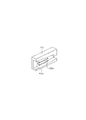
As shown in FIG. 12, the
[0040]
The receiving
[0041]
That is, the front
[0042]
The operation of the user when changing such a mode will be described with reference to FIGS. First, as shown in FIG. 18, the front
[0043]
Next, as shown in FIG. 21, the
[0044]
As a result, as shown in FIG. 24, a part of the
[0045]
In the
[0046]
Finally, as shown in FIG. 26, each front
[0047]
On the other hand, as shown in FIG. 24, when a part of the
[0048]
On the other hand, as shown in FIG. 24, when a part of the
[0049]
On the other hand, as shown in FIG. 24, when a part of the
[0050]
As a result, as shown in FIGS. 32 and 33, a part of the
[0051]
In the above-described embodiment, the case where the receiving
[0052]
【The invention's effect】
As described above, according to the recording medium receiving apparatus and the printer including the receiving apparatus according to the present invention, the hook member is disposed at a desired position, is hung on the desired hook member with the shaft, and the sheet member. Can be folded, bent or stretched to form a desired recording medium receiving portion. Therefore, it is possible to easily change the usage mode of the receiving device, and there is no hindrance during the transporting operation of the printer, and it is possible to remove the recording medium of a predetermined size from the front side of the printer. It can be done easily.
[Brief description of the drawings]
FIG. 1 is a perspective view illustrating a configuration example of a printer according to an embodiment of the present invention.
FIG. 2 is a perspective view illustrating an example of an internal configuration of a main part of the printer of FIG.
FIG. 3 is a first diagram illustrating a procedure for using the printer of FIG. 1;
FIG. 4 is a second diagram illustrating a procedure for using the printer of FIG. 1;
FIG. 5 is a third diagram showing a procedure for using the printer of FIG. 1;
6 is a fourth diagram illustrating a procedure for using the printer of FIG. 1; FIG.
7 is a fifth diagram showing a procedure for using the printer of FIG. 1. FIG.
FIG. 8 is a sixth diagram illustrating a procedure for using the printer of FIG. 1;
FIG. 9 is a seventh diagram illustrating a procedure for using the printer of FIG. 1;
10 is an eighth diagram illustrating a procedure for using the printer of FIG. 1. FIG.
FIG. 11 is a first perspective view showing an outline of a recording medium receiving apparatus which is a characteristic part of the present invention.
FIG. 12 is a second perspective view showing the outline of a recording medium receiving apparatus which is a characteristic part of the present invention.
13 is a three-sided view showing details of a front upper hook (front lower hook) of the receiving device of FIG. 11. FIG.
14 is a perspective view showing details of a hook holder of the receiving device of FIG. 11. FIG.
15 is a side view showing the operation of the front upper hook member of FIGS. 13 and 14. FIG.
16 is a perspective view showing details of another hook holder of the receiving device of FIG. 11. FIG.
17 is a side view showing the operation of the front lower hook member of FIGS. 13 and 16. FIG.
18 is a first diagram for explaining a user's operation when changing the mode of the receiving device of FIGS. 11 and 12. FIG.
FIG. 19 is a second diagram for explaining the operation of the user when changing the mode of the receiving device of FIGS. 11 and 12;
FIG. 20 is a third diagram for explaining the operation of the user when changing the mode of the receiving device of FIGS. 11 and 12;
FIG. 21 is a fourth diagram for explaining the operation of the user when changing the mode of the receiving device of FIGS. 11 and 12;
FIG. 22 is a fifth diagram for explaining the operation of the user when changing the mode of the receiving device of FIGS. 11 and 12;
FIG. 23 is a sixth diagram for explaining the operation of the user when changing the mode of the receiving device of FIG. 11 and FIG. 12;
FIG. 24 is a seventh diagram for explaining a user's operation when changing the mode of the receiving device of FIG. 11 and FIG. 12;
FIG. 25 is an eighth diagram for explaining the operation of the user when changing the mode of the receiving device of FIG. 11 and FIG. 12;
FIG. 26 is a ninth diagram for explaining the operation of the user when changing the mode of the receiving device of FIG. 11 and FIG. 12;
FIG. 27 is a tenth view for explaining a user's operation when changing the mode of the receiving device of FIG. 11 and FIG. 12;
FIG. 28 is an eleventh view for explaining a user's operation when changing the mode of the receiving device of FIGS. 11 and 12;
FIG. 29 is a twelfth view for explaining the operation of the user when changing the mode of the receiving device of FIG. 11 and FIG. 12;
30 is a thirteenth view for explaining a user's operation when changing the mode of the receiving device of FIGS. 11 and 12. FIG.
FIG. 31 is a fourteenth diagram for explaining a user's operation when changing the mode of the receiving device of FIG. 11 and FIG. 12;
FIG. 32 is a fifteenth view for explaining the operation of the user when changing the mode of the receiving apparatus of FIG. 11 and FIG. 12;
FIG. 33 is a sixteenth diagram for explaining the operation of the user when changing the mode of the receiving device of FIG. 11 and FIG. 12;
[Explanation of symbols]
100 printer
110 Paper feed unit
111 Roll paper holder
112 Roll paper cover
113 spindle
114 Spindle holder
115 Spindle holder
120 Printing section
121 print head
122 Carriage
123 FFC
124 ink tube
125 Top cover
126 Front lid
127 rail
128 Carriage belt
130 Paper discharge unit
131 Paper ejection guide
132 Side cover
140 legs
141 Roll
142 Support pillar
143 Reinforcing rod
150 Cartridge holder
400 receiving device
410 Rear hook member
420 Front hook member
421 Front upper hook
422 Bar
423 Retaining material
425 Hook holder
426 first hook holder
427 Second hook holder
430 Front lower hook member
431 Front lower hook
432 Bar
433 Holding material
435 hook holder
440 Sheet member
441, 442, 443, 444 Shaft
Claims (2)
前記受け装置は、
矩形状に形成された柔軟性を有するシート部材と、
記録媒体の排出方向における前記シート部材の両端部、及びその中間部を係留する複数のシャフトと、
任意の位置に配置可能であって、前記シャフトの端部を係止可能な複数の係止部材と、を備え、
前記シャフトのうち、前記シート部材の中間部を係留するシャフトは、
所定間隔をあけて平行に配置された長さの異なる2本のシャフトと、
前記2本のシャフトを一体に固定保持する接続部材と、を備え、
前記2本のシャフトのうち、
長さが短いシャフトの両端部は、前記接続部材に固定され、
長さが長いシャフトの両端部は、前記接続部材を貫通して前記係止部材に回転可能に支持されることを特徴とするプリンタ。In a printer provided with a receiving device for receiving a discharged recording medium,
The receiving device is
A flexible sheet member formed in a rectangular shape;
A plurality of shafts mooring both end portions of the sheet member in the recording medium discharge direction and intermediate portions thereof;
A plurality of locking members that can be arranged at any position and can lock the end of the shaft;
Of the shafts, the shaft that anchors the intermediate portion of the sheet member is:
Two shafts of different lengths arranged in parallel at a predetermined interval;
And a connecting member for fixedly holding together the two shafts,
Of the two shafts,
Both ends of the shaft having a short length are fixed to the connection member,
Both ends of a long shaft length, a printer, characterized in that it is rotatably supported on the locking member through said connecting member.
Priority Applications (1)
| Application Number | Priority Date | Filing Date | Title |
|---|---|---|---|
| JP2000404659A JP4604350B2 (en) | 2000-12-28 | 2000-12-28 | Recording medium receiving apparatus and printer having the receiving apparatus |
Applications Claiming Priority (1)
| Application Number | Priority Date | Filing Date | Title |
|---|---|---|---|
| JP2000404659A JP4604350B2 (en) | 2000-12-28 | 2000-12-28 | Recording medium receiving apparatus and printer having the receiving apparatus |
Related Child Applications (2)
| Application Number | Title | Priority Date | Filing Date |
|---|---|---|---|
| JP2009171875A Division JP2009234795A (en) | 2009-07-23 | 2009-07-23 | Printer |
| JP2009171874A Division JP4849157B2 (en) | 2009-07-23 | 2009-07-23 | Printer |
Publications (3)
| Publication Number | Publication Date |
|---|---|
| JP2002205862A JP2002205862A (en) | 2002-07-23 |
| JP2002205862A5 JP2002205862A5 (en) | 2007-05-31 |
| JP4604350B2 true JP4604350B2 (en) | 2011-01-05 |
Family
ID=18868582
Family Applications (1)
| Application Number | Title | Priority Date | Filing Date |
|---|---|---|---|
| JP2000404659A Expired - Fee Related JP4604350B2 (en) | 2000-12-28 | 2000-12-28 | Recording medium receiving apparatus and printer having the receiving apparatus |
Country Status (1)
| Country | Link |
|---|---|
| JP (1) | JP4604350B2 (en) |
Families Citing this family (7)
| Publication number | Priority date | Publication date | Assignee | Title |
|---|---|---|---|---|
| JP5142541B2 (en) * | 2007-01-31 | 2013-02-13 | キヤノン株式会社 | Recording device and media storage device |
| JP2015189559A (en) | 2014-03-28 | 2015-11-02 | セイコーエプソン株式会社 | recording device |
| JP6613571B2 (en) * | 2015-02-03 | 2019-12-04 | セイコーエプソン株式会社 | Recording device |
| JP6039764B2 (en) * | 2015-07-22 | 2016-12-07 | キヤノン株式会社 | Recording device |
| JP6566814B2 (en) * | 2015-09-29 | 2019-08-28 | キヤノン株式会社 | Printing device |
| JP7272139B2 (en) * | 2019-06-28 | 2023-05-12 | セイコーエプソン株式会社 | Media processing device, loading device and media loading method |
| JP6950803B1 (en) * | 2020-10-13 | 2021-10-13 | セイコーエプソン株式会社 | Processing equipment and recording equipment |
Citations (5)
| Publication number | Priority date | Publication date | Assignee | Title |
|---|---|---|---|---|
| JPH0261864U (en) * | 1988-10-31 | 1990-05-09 | ||
| JPH0761681A (en) * | 1993-06-15 | 1995-03-07 | Graphtec Corp | Recorded recording medium receiver of recording device |
| JP2000034050A (en) * | 1998-07-16 | 2000-02-02 | Mutoh Ind Ltd | Paper storage unit of plotter |
| JP2000159411A (en) * | 1998-11-27 | 2000-06-13 | Seiko Epson Corp | Fixing lever attaching device in large-sized printer |
| JP2000159412A (en) * | 1998-11-27 | 2000-06-13 | Seiko Epson Corp | Paper discharge device in large-sized printer |
-
2000
- 2000-12-28 JP JP2000404659A patent/JP4604350B2/en not_active Expired - Fee Related
Patent Citations (5)
| Publication number | Priority date | Publication date | Assignee | Title |
|---|---|---|---|---|
| JPH0261864U (en) * | 1988-10-31 | 1990-05-09 | ||
| JPH0761681A (en) * | 1993-06-15 | 1995-03-07 | Graphtec Corp | Recorded recording medium receiver of recording device |
| JP2000034050A (en) * | 1998-07-16 | 2000-02-02 | Mutoh Ind Ltd | Paper storage unit of plotter |
| JP2000159411A (en) * | 1998-11-27 | 2000-06-13 | Seiko Epson Corp | Fixing lever attaching device in large-sized printer |
| JP2000159412A (en) * | 1998-11-27 | 2000-06-13 | Seiko Epson Corp | Paper discharge device in large-sized printer |
Also Published As
| Publication number | Publication date |
|---|---|
| JP2002205862A (en) | 2002-07-23 |
Similar Documents
| Publication | Publication Date | Title |
|---|---|---|
| US7121543B2 (en) | Recording medium receiver and recording apparatus incorporating the same | |
| EP1820655B1 (en) | Printing apparatus | |
| JP4849157B2 (en) | Printer | |
| US20080277851A1 (en) | Rolled medium supporting device for supporting both ends of rolled medium and recording apparatus having the rolled medium supporting device | |
| JP3928705B2 (en) | Roll recording medium holding means and recording apparatus | |
| JP4604350B2 (en) | Recording medium receiving apparatus and printer having the receiving apparatus | |
| US6752553B2 (en) | Recording apparatus | |
| JP2002205855A (en) | Recorder | |
| JP4539365B2 (en) | Medium receiving apparatus and recording apparatus | |
| JP2002211821A (en) | Receiving device of recording medium and recording device provided with the same | |
| JP4470318B2 (en) | Inkjet printer | |
| JP2007062977A (en) | Discharged medium receiving device and recording device | |
| JP2009234795A (en) | Printer | |
| JP4016254B2 (en) | ROLL RECORDING MEDIUM SUPPORT MEMBER AND RECORDING DEVICE | |
| JP2002200768A (en) | Ink-jet printer and ink tube binder | |
| JP2007106084A (en) | Recording liquid cartridge and image formation device | |
| JP2004067359A (en) | Roll shaft, recording medium supplying device, and recording device | |
| JP2002166569A (en) | Ink jet type printer | |
| JP3643277B2 (en) | Ink ribbon cassette | |
| JP3818145B2 (en) | Recording device | |
| JP2002205850A (en) | Printer | |
| JPH04303336A (en) | Automatic paper sheet feed device | |
| JP3797211B2 (en) | Recording device | |
| JP2003326815A (en) | Method for detecting width of recording medium, width detector and recorder | |
| JP2002205869A (en) | Printer and cutter for storage medium |
Legal Events
| Date | Code | Title | Description |
|---|---|---|---|
| A521 | Written amendment |
Free format text: JAPANESE INTERMEDIATE CODE: A523 Effective date: 20070409 |
|
| A621 | Written request for application examination |
Free format text: JAPANESE INTERMEDIATE CODE: A621 Effective date: 20070409 |
|
| RD03 | Notification of appointment of power of attorney |
Free format text: JAPANESE INTERMEDIATE CODE: A7423 Effective date: 20071228 |
|
| A977 | Report on retrieval |
Free format text: JAPANESE INTERMEDIATE CODE: A971007 Effective date: 20090421 |
|
| A131 | Notification of reasons for refusal |
Free format text: JAPANESE INTERMEDIATE CODE: A131 Effective date: 20090526 |
|
| A521 | Written amendment |
Free format text: JAPANESE INTERMEDIATE CODE: A523 Effective date: 20090723 |
|
| A02 | Decision of refusal |
Free format text: JAPANESE INTERMEDIATE CODE: A02 Effective date: 20100302 |
|
| A521 | Written amendment |
Free format text: JAPANESE INTERMEDIATE CODE: A523 Effective date: 20100601 |
|
| A911 | Transfer of reconsideration by examiner before appeal (zenchi) |
Free format text: JAPANESE INTERMEDIATE CODE: A911 Effective date: 20100609 |
|
| TRDD | Decision of grant or rejection written | ||
| A01 | Written decision to grant a patent or to grant a registration (utility model) |
Free format text: JAPANESE INTERMEDIATE CODE: A01 Effective date: 20100907 |
|
| A01 | Written decision to grant a patent or to grant a registration (utility model) |
Free format text: JAPANESE INTERMEDIATE CODE: A01 |
|
| A61 | First payment of annual fees (during grant procedure) |
Free format text: JAPANESE INTERMEDIATE CODE: A61 Effective date: 20100920 |
|
| R150 | Certificate of patent or registration of utility model |
Free format text: JAPANESE INTERMEDIATE CODE: R150 |
|
| FPAY | Renewal fee payment (event date is renewal date of database) |
Free format text: PAYMENT UNTIL: 20131015 Year of fee payment: 3 |
|
| S531 | Written request for registration of change of domicile |
Free format text: JAPANESE INTERMEDIATE CODE: R313532 |
|
| R350 | Written notification of registration of transfer |
Free format text: JAPANESE INTERMEDIATE CODE: R350 |
|
| LAPS | Cancellation because of no payment of annual fees |