JP4603291B2 - Endoscope device - Google Patents
Endoscope device Download PDFInfo
- Publication number
- JP4603291B2 JP4603291B2 JP2004152467A JP2004152467A JP4603291B2 JP 4603291 B2 JP4603291 B2 JP 4603291B2 JP 2004152467 A JP2004152467 A JP 2004152467A JP 2004152467 A JP2004152467 A JP 2004152467A JP 4603291 B2 JP4603291 B2 JP 4603291B2
- Authority
- JP
- Japan
- Prior art keywords
- optical adapter
- endoscope
- side terminal
- led group
- terminal
- Prior art date
- Legal status (The legal status is an assumption and is not a legal conclusion. Google has not performed a legal analysis and makes no representation as to the accuracy of the status listed.)
- Expired - Fee Related
Links
Images


Classifications
-
- A—HUMAN NECESSITIES
- A61—MEDICAL OR VETERINARY SCIENCE; HYGIENE
- A61B—DIAGNOSIS; SURGERY; IDENTIFICATION
- A61B1/00—Instruments for performing medical examinations of the interior of cavities or tubes of the body by visual or photographical inspection, e.g. endoscopes; Illuminating arrangements therefor
- A61B1/00112—Connection or coupling means
- A61B1/00121—Connectors, fasteners and adapters, e.g. on the endoscope handle
- A61B1/00124—Connectors, fasteners and adapters, e.g. on the endoscope handle electrical, e.g. electrical plug-and-socket connection
-
- A—HUMAN NECESSITIES
- A61—MEDICAL OR VETERINARY SCIENCE; HYGIENE
- A61B—DIAGNOSIS; SURGERY; IDENTIFICATION
- A61B1/00—Instruments for performing medical examinations of the interior of cavities or tubes of the body by visual or photographical inspection, e.g. endoscopes; Illuminating arrangements therefor
- A61B1/06—Instruments for performing medical examinations of the interior of cavities or tubes of the body by visual or photographical inspection, e.g. endoscopes; Illuminating arrangements therefor with illuminating arrangements
- A61B1/0661—Endoscope light sources
- A61B1/0676—Endoscope light sources at distal tip of an endoscope
-
- A—HUMAN NECESSITIES
- A61—MEDICAL OR VETERINARY SCIENCE; HYGIENE
- A61B—DIAGNOSIS; SURGERY; IDENTIFICATION
- A61B1/00—Instruments for performing medical examinations of the interior of cavities or tubes of the body by visual or photographical inspection, e.g. endoscopes; Illuminating arrangements therefor
- A61B1/06—Instruments for performing medical examinations of the interior of cavities or tubes of the body by visual or photographical inspection, e.g. endoscopes; Illuminating arrangements therefor with illuminating arrangements
- A61B1/0661—Endoscope light sources
- A61B1/0684—Endoscope light sources using light emitting diodes [LED]
-
- A—HUMAN NECESSITIES
- A61—MEDICAL OR VETERINARY SCIENCE; HYGIENE
- A61B—DIAGNOSIS; SURGERY; IDENTIFICATION
- A61B1/00—Instruments for performing medical examinations of the interior of cavities or tubes of the body by visual or photographical inspection, e.g. endoscopes; Illuminating arrangements therefor
- A61B1/06—Instruments for performing medical examinations of the interior of cavities or tubes of the body by visual or photographical inspection, e.g. endoscopes; Illuminating arrangements therefor with illuminating arrangements
- A61B1/0607—Instruments for performing medical examinations of the interior of cavities or tubes of the body by visual or photographical inspection, e.g. endoscopes; Illuminating arrangements therefor with illuminating arrangements for annular illumination
Description
本発明は、内視鏡挿入部の先端部に着脱自在である内視鏡用光学アダプタを有する内視鏡装置に関する。 The present invention relates to an endoscope apparatus having an endoscope optical adapter that is detachably attached to a distal end portion of an endoscope insertion portion.
周知のように、内視鏡は、医療分野及び工業用分野において広く利用されている。医療分野において用いられる内視鏡は、細長い挿入部を体腔内に挿入することによって、体腔内の臓器を観察したり、必要に応じて処置具の挿通チャンネル内に挿入した処置具を用いて各種処置をしたりすることができる。 As is well known, endoscopes are widely used in the medical field and the industrial field. Endoscopes used in the medical field include various types of treatment tools that are used to observe organs in a body cavity by inserting an elongated insertion portion into a body cavity, or inserted into an insertion channel of a treatment tool as necessary. Can be treated.
また、工業用分野において用いられる内視鏡は、細長い挿入部をジェットエンジン内や、発電所の配管等に挿入することによって、被検部位の傷及び腐蝕等の観察や各種処置等を行うことができる。 In addition, endoscopes used in the industrial field perform observations and various treatments of damaged and corroded sites by inserting a long and thin insertion part into a jet engine or piping of a power plant. Can do.
内視鏡の挿入部の先端に、湾曲部が設けられ、内視鏡の操作部を操作して湾曲部を湾曲させることによって、挿入部内に配設された観察光学系の先端部の対物レンズの観察方向を変更させることができる。 A bending portion is provided at the distal end of the insertion portion of the endoscope. The objective lens at the distal end portion of the observation optical system disposed in the insertion portion by operating the operation portion of the endoscope to bend the bending portion. The observation direction can be changed.
また、内視鏡挿入部の湾曲部及び先端部に、観察光学系の先端部の対物レンズが観察している被検体を照明する照明光学系が配設されている。該照明光学系の照明に、複数の発光ダイオード(以下、LEDと称す)を用いることも周知であり、実用化されている。 Further, an illumination optical system for illuminating a subject observed by the objective lens at the distal end of the observation optical system is disposed on the bending portion and the distal end of the endoscope insertion portion. The use of a plurality of light emitting diodes (hereinafter referred to as LEDs) for illumination of the illumination optical system is also well known and has been put into practical use.
ところで、LEDは、静電気に対して非常に弱い特性を有しているため、何らかの要因により、LEDの両極端間に、静電気の電圧が印加されてしまうと、LEDは、静電気破壊されてしまい、被検体を照明できなくなってしまうといった問題があった。 By the way, since the LED has a characteristic that is very weak against static electricity, if an electrostatic voltage is applied between the extremes of the LED for some reason, the LED is destroyed due to static electricity. There was a problem that the specimen could not be illuminated.
このような問題に鑑み、特許文献1には、LEDの両極端間に、インダクタ、コンデンサ及びダイオード等から構成される静電気保護回路を接続し、LEDの両極端間に、静電気の電圧が印加されることにより、LEDが静電気破壊されるのを防止する技術の提案がなされている。
In view of such problems,
また、特許文献2には、内視鏡挿入部の先端部に配設された電源回路に、トランジスタ及びダイオード等を接続し、簡単な回路構成により、内視鏡挿入部の先端部に配設された照明用回路を含む電源回路に、静電気の電圧が印加されることに起因する電源回路の静電気破壊を防止する技術の提案がなされている。
ところで、内視鏡挿入部の先端部に着脱自在であり、装着された際、内視鏡の視野方向及び視野角等の光学特性を変換する光学アダプタも周知である。また、光学アダプタに、複数のLEDを配設することにより照明能力を向上させたり、複数のLEDの内、個々のLEDの配置位置を変えることにより、照明方向を変化させたりすることもできる。 By the way, an optical adapter that is detachably attached to the distal end portion of the endoscope insertion portion and converts optical characteristics such as a viewing direction and a viewing angle of the endoscope when mounted is also well known. Further, it is possible to improve the illumination capability by arranging a plurality of LEDs in the optical adapter, or to change the illumination direction by changing the arrangement position of each of the plurality of LEDs.
取扱者により光学アダプタが内視鏡挿入部から脱却されると、該内視鏡挿入部の電気接点と接触するLEDの端子は、光学アダプタから露出される。この際、取扱者が光学アダプタに触れることにより光学アダプタに静電気が印加されると、LEDの端子に静電気の電圧が印加されてしまい、その結果、LEDが静電気破壊されてしまうといった問題があった。よって、光学アダプタを取扱う際には、取扱い者をアースしたりする必要があるなど、非常に神経を使わねばならず使い勝手が悪い。 When the operator removes the optical adapter from the endoscope insertion portion, the terminal of the LED that is in contact with the electrical contact of the endoscope insertion portion is exposed from the optical adapter. At this time, when static electricity is applied to the optical adapter by the operator touching the optical adapter, static electricity voltage is applied to the terminal of the LED, and as a result, there is a problem that the LED is electrostatically destroyed. . Therefore, when handling the optical adapter, it is necessary to ground the handler, and it is necessary to use a nerve, which is inconvenient.
本発明は、上記問題点及び上記事情に鑑みてなされたものであり、その目的は、取扱い易く、印加される静電気の電圧に対し信頼性を高めた内視鏡用光学アダプタ、及び該内視鏡用光学アダプタと内視鏡挿入部とにより構成される内視鏡装置を提供することにある。 The present invention has been made in view of the above problems and the above circumstances, and an object of the present invention is to provide an endoscope optical adapter that is easy to handle and has improved reliability against an applied electrostatic voltage, and the endoscope. An object of the present invention is to provide an endoscope apparatus including a mirror optical adapter and an endoscope insertion portion.
上記目的を達成するために本発明による内視鏡装置は、内視鏡挿入部と、外装筐体と、照明用の光源となる発光体と、前記外装筐体内から外方に突出するよう前記発光体の両極端間に接続された2つの端子からなる第1の端子部と、前記2つの端子の間に設けられ、前記内視鏡挿入部の先端部に設けられた第2の端子部が前記第1の端子部に接触していない場合において短絡状態を維持し、かつ、前記第2の端子部が前記第1の端子部に接触している場合において開放状態になることにより前記発光体の両極端間と前記他の端子とを電気的に導通させることができるように構成されたスイッチ部と、を備えた内視鏡用光学アダプタと、を有し、前記内視鏡挿入部は、前記内視鏡用光学アダプタに装着した際に前記スイッチ部に接触して前記スイッチ部を開放状態にする突出部を備えている。 In order to achieve the above object, an endoscope apparatus according to the present invention includes an endoscope insertion portion, an exterior casing, a light emitting body serving as a light source for illumination, and the outer casing projecting outward from the exterior casing. A first terminal portion composed of two terminals connected between the extremes of the light emitter, and a second terminal portion provided between the two terminals and provided at the distal end portion of the endoscope insertion portion. The light emitter is maintained by maintaining a short-circuited state when not in contact with the first terminal part, and being in an open state when the second terminal part is in contact with the first terminal part. And an optical adapter for an endoscope provided with a switch part configured to be able to electrically connect between the extremes and the other terminal, the endoscope insertion part, When attached to the endoscope optical adapter, the switch portion comes into contact with the switch. And a protrusion that the pitch portion in an open state.
本発明によれば、取扱い易く、印加される静電気の電圧に対し信頼性を高めた内視鏡装置を提供することができる。 According to the present invention, easy to handle, to the voltage of the applied static electricity can be provided a endoscope apparatus among with improved reliability.
以下、図面を参照して本発明の実施の形態を説明する。
(第1実施の形態)
図1は、本発明の第1実施の形態を示す内視鏡用光学アダプタ及び該内視鏡用光学アダプタが装着される内視鏡装置の斜視図である。尚、本実施の形態においては、内視鏡装置は、工業用の内視鏡装置を例に挙げて説明する。
Embodiments of the present invention will be described below with reference to the drawings.
(First embodiment)
FIG. 1 is a perspective view of an endoscope optical adapter and an endoscope apparatus to which the endoscope optical adapter is attached according to a first embodiment of the present invention. In the present embodiment, the endoscope apparatus will be described taking an industrial endoscope apparatus as an example.
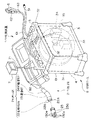
図1に示すように、内視鏡装置1は、例えば工業用の内視鏡(以下、内視鏡と称す)2と、収納ケース8とにより、主要部が構成されている。収納ケース8は、箱体81と、該箱体81の上部に開閉自在に接続された蓋体82とにより構成され、未使用の際には内視鏡2等が収納される。
As shown in FIG. 1, an
収納ケース8の箱体81の内部に、内視鏡2の収納の際、内視鏡2の挿入部21を外周面部31に巻き取る収納部であるドラム部3、光源部32、カメラコントロールユニット33、電動湾曲駆動部34、電動湾曲回路部35、電源部等が収納されたフレーム部4が配設されている。フレーム部4は、ドラム部3を回動自在に支持している。また、ドラム部3は、管状部材により構成され、フランジ形状を有している。
Inside the
箱体81の上部に、各種スイッチ類、コネクタ類及び給排気用ダクトが配設されたフロントパネル5が形成されている。具体的には、フロントパネル5の上面に、フレーム部4の内部に収納された各種部材及び内視鏡2に電源を供給するためのACケーブル51の一端が接続されている。
A front panel 5 in which various switches, connectors, and air supply / exhaust ducts are disposed is formed on the top of the
また、フロントパネル5の上面に、内視鏡2によって撮像された被検部位の画像を表示するモニタ7を回動自在に支持する伸縮式のポール71が接続されている。さらにフロントパネル5の上面には、リモートコントローラ(以下、リモコンと称す)6のケーブル61が着脱自在に接続されている。
In addition, a
リモコン6に、ジョイスティック62が設けられており、ジョイスティック62は、内視鏡2の挿入部21の湾曲部23を湾曲操作する際の湾曲入力制御部となる。また、リモコン6に、フレーム部4の内部に収納された各種部材及び内視鏡2用の電源オン釦63が設けられている。
A
さらに、フロントパネル5の上面に、内視鏡2の挿入部21を箱体81に対して出し入れするための開口が形成された座屈防止用のゴム部材52が配設されている。座屈防止用のゴム部材52は、内視鏡2の挿入部21が箱体81から取り出された際、内視鏡2の挿入部21がフロントパネル5の出口付近において座屈するのを防止する。
Further, on the upper surface of the front panel 5, a
内視鏡2は、柔軟性を有する細長の挿入部21を備えており、内視鏡2を使用する際は、挿入部21は、フロントパネル5から座屈防止用のゴム部材52を介して延出される。挿入部21に、先端側から順に硬質の先端部本体22、湾曲部23及び細長の柔軟性を有する可撓管部24が連設されている。
The endoscope 2 includes an elongated insertion portion 21 having flexibility. When the endoscope 2 is used, the insertion portion 21 is inserted from the front panel 5 through a
湾曲部23は、多方向に湾曲自在となるよう形成されており、湾曲部23は、リモコン6の操作により湾曲操作されることにより、先端部本体22内に配設された、観察光学系の対物レンズ(いずれも図示されず)の観察方向を所望の方向に変更させることができる。 The bending portion 23 is formed so as to be bendable in multiple directions. The bending portion 23 is bent by an operation of the remote controller 6, whereby the bending portion 23 of the observation optical system disposed in the distal end portion main body 22 is formed. The observation direction of the objective lens (both not shown) can be changed to a desired direction.
また、先端部本体22の先端に、後述する内視鏡用光学アダプタ(以下、単に光学アダプタと称す)25が装着された際、光学アダプタ25内に配設されたLED群130のアノード側の端子130A、及びカソード側の端子130B(いずれも図2参照)の接触端と電気的に接触する端子22A、22Bがそれぞれ配設されている。
Further, when an endoscope optical adapter (hereinafter simply referred to as an optical adapter) 25 to be described later is attached to the distal end of the distal end body 22, the anode side of the
端子22A、22Bは、先端部本体22の先端に光学アダプタ25が装着された際、光学アダプタ25のアノード側の端子130A、及びカソード側の端子130Bに、フレーム部4に配設された上記電源からの電力を供給する。
When the
内視鏡挿入部21の先端部本体22の先端に、視野方向及び視野角等の光学特性を変換する光学アダプタ25が着脱自在に装着される。光学アダプタ25は、例えば金属により構成された筒状の外装筐体25Gを有し、該外装筐体25G内の先端部に、複数の発光体であるLED130d1〜130d4から構成されたLED群130が配設されている。
An
光学アダプタ25の先端部の内部に、LED群130を配設することにより、内視鏡2の照明能力を向上させたり、個々のLED130dの配置位置を変えることにより、被検体への照明方向を変化させたりすることができる。
By disposing the
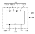
図2は、図1中の光学アダプタ25の外装筐体25Gの内部に配設されたLED群130の発光回路を示した電気回路図である。
図2に示すように、光学アダプタ25の外装筐体25G内に、LED130d1〜130d4が、例えば4個直列に接続されて構成されたLED群130が配設されている。LED群130の両極端間となる、LED群130を構成するLED130d1のアノード、LED130d4のカソード間に、端子部であるアノード側の端子130A、及びカソード側の端子130Bが接続されている。尚、以下、LED130d1のアノードをLED群130のアノード、LED130d4のカソードをLED群130のカソードと称して説明する。
FIG. 2 is an electric circuit diagram showing a light emitting circuit of the
As shown in FIG. 2, an
詳しくは、アノード側の端子130A、及びカソード側の端子130Bの端子22A,22Bとの接触端が、上記外装筐体25Gから、挿入部21側に突出するよう、アノード側の端子130A、及びカソード側の端子130Bは、LED群130の両極端間に接続されている。
Specifically, the anode-
また、LED群130の両極端間に、静電気保護手段であるダイオード160が接続されている。ダイオード160のアノードは、LED群130のカソードと接続され、ダイオード160のカソードは、LED群130のアノードと接続されている。
In addition, a
次にこのように構成された光学アダプタ25の作用について説明する。
アノード側の端子130A、及びカソード側の端子130Bの接触端は、光学アダプタ25が内視鏡挿入部21の先端部本体22に装着された際、先端部本体22に配設された端子22A,22Bとそれぞれ電気的に接触する。
Next, the operation of the
The contact ends of the anode-
このことにより、挿入部21側から供給された電力は、アノード側の端子130A、及びカソード側の端子130Bを介してLED群130に印加される。よって、LED群130は発光する。
Thus, the power supplied from the insertion portion 21 side is applied to the
また、光学アダプタ25を、先端部本体22から脱却した後、静電気が発生したとしても、該静電気はアノード側の端子130A、及びカソード側の端子130Bに流れるようになっている。
Further, even if static electricity is generated after the
詳しくは、アノード側の端子130A、カソード側の端子130B間において、カソード側の端子130Bに、正の静電気の電圧が印加された際、LED群130の両極端間にダイオード160が接続されているため、電圧の高い上記静電気は、ダイオード160を通って、アノード側の端子130Aへ流れる。
Specifically, the
このことより、カソード側の端子130Bに取扱者から静電気の電圧が印加されたとしても、LED群130の両極端間には、静電気の電圧が印加されない。よって、LED群130を静電気から保護することができるため、LED群130が静電気破壊され難い。
For this reason, even if a static voltage is applied from the operator to the cathode-
また、光学アダプタ25を取扱う際、取扱い者にアースを施す必要がないため、光学アダプタ25の取扱いが容易となる。
以上から、印加される静電気に対し、信頼性の高い光学アダプタが実現できる。
Further, when the
As described above, a highly reliable optical adapter can be realized with respect to applied static electricity.
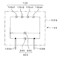
以下、本実施の形態における変形例を図3を用いて示す。図3は、図1中の光学アダプタ25の外装筐体25Gの内部に配設されたLED群130の発光回路の変形例を示した電気回路図である。
Hereinafter, a modification of the present embodiment will be described with reference to FIG. FIG. 3 is an electric circuit diagram showing a modification of the light emitting circuit of the
本実施の形態においては、LED群130の両極端間に、静電気保護手段であるダイオード160が接続されていると示した。これに限らず、図3に示すように、LED群130の両極端間に、静電気保護手段であるツェナダイオード260が接続されていてもよい。ツェナダイオード260のアノードは、LED群130のカソードと接続され、ツェナダイオード260のカソードは、LED群130のアノードと接続されている。
In the present embodiment, it has been shown that the
次にこのように構成された光学アダプタ25の作用について説明する。
光学アダプタ25を、先端部本体22から脱却した後、静電気が発生したとしても、該静電気はアノード側の端子130A、及びカソード側の端子130Bに流れるようになっている。
Next, the operation of the
Even if static electricity is generated after the
詳しくは、アノード側の端子130A、カソード側の端子130B間において、アノード側の端子130Aに、正の静電気の電圧が印加された際、LED群130の両極端間にツェナダイオード260が接続されているため、電圧の高い上記静電気は、ツェナダイオード260を通って、カソード側の端子130Bへ流れる。
Specifically, a
このことより、アノード側の端子130Aに静電気の電圧が印加されたとしても、LED群130の両極端間には、取扱者から静電気の電圧が印加されない。よって、LED群130を静電気から保護することができるため、LED群130が静電気破壊され難い。
For this reason, even if a static voltage is applied to the anode-
また、光学アダプタ25を取扱う際、取扱い者にアースを施す必要がないため、光学アダプタ25の取扱いが容易となる。
以上から、印加される静電気に対し、信頼性の高い光学アダプタが実現できる。
Further, when the
As described above, a highly reliable optical adapter can be realized with respect to applied static electricity.
さらに、以下、別の変形例を図4を用いて説明する。図4は、図1中の光学アダプタ25の外装筐体25Gの内部に配設されたLED群130の発光回路のさらに別の変形例を示した電気回路図である。
Furthermore, another modification will be described below with reference to FIG. FIG. 4 is an electric circuit diagram showing still another modification of the light emitting circuit of the
LED群130の両極端間に、静電気保護手段であるダイオード160またはツェナダイオード260が接続されていると示した。これに限らず、図4に示すように、LED群130の両極端間に、静電気保護手段であるバリスタ360が接続されていてもよい。
It has been shown that the
バリスタ360は、電流が通過する際の方向性はないが、一定電圧以上のおいて、オン状態となる性質を有しているため、LED群130の両極端間に、静電気保護手段であるダイオード160またはツェナダイオード260が接続されている場合と同様の効果を得ることができる。
The
(第2実施の形態)
図5は、本発明の第2実施の形態を示す内視鏡装置における光学アダプタの外装筐体の内部に配設されたLED群の発光回路を示した電気回路図である。
(Second Embodiment)
FIG. 5 is an electric circuit diagram showing a light emitting circuit of a group of LEDs arranged in the exterior casing of the optical adapter in the endoscope apparatus showing the second embodiment of the present invention.
この第2実施の形態の光学アダプタの発光回路の構成は、上記図1乃至図4に示した光学アダプタの発光回路と比して、LED群130の両極端間に、接続される静電気保護手段が並列回路により構成されている点のみが異なる。よって、この相違点のみを説明し、第1実施の形態と同様の構成には同じ符号を付し、その説明は省略する。 The configuration of the light-emitting circuit of the optical adapter according to the second embodiment is different from the light-emitting circuit of the optical adapter shown in FIG. 1 to FIG. The only difference is that it is constituted by a parallel circuit. Therefore, only this difference will be described, the same reference numerals are given to the same components as those in the first embodiment, and the description thereof will be omitted.
図5に示すように、光学アダプタ125の外装筐体125G内に、LED130d1〜d4が、例えば4個直列に接続されたLED群130が配設されている。LED群130の両極端間である両極端間に、端子部であるアノード側の端子130A、及びカソード側の端子130Bが接続されている。
As shown in FIG. 5, an
詳しくは、アノード側の端子130A、及びカソード側の端子130Bの端子22A,22Bとの接触端が、上記外装筐体125Gから、挿入部21側に突出するよう、アノード側の端子130A、及びカソード側の端子130Bは、LED群130の両極端間に接続されている。
Specifically, the anode-
また、LED群130の両極端間に、静電気保護手段であるダイオード160とツェナダイオード260との並列回路400が接続されている。ダイオード160及びツェナダイオード260のアノードは、LED群130のカソードと接続され、ダイオード160及びツェナダイオード260のカソードは、LED群130のアノードと接続されている。
Further, a
次にこのように構成された光学アダプタ125の作用について説明する。
アノード側の端子130A、及びカソード側の端子130Bの接触端は、光学アダプタ125が、内視鏡挿入部21の先端部本体22の先端に装着された際、先端部本体22に配設された端子22A,22Bとそれぞれ電気的に接触する。
Next, the operation of the
The contact ends of the anode-
このことにより、挿入部21側から供給された電力は、アノード側の端子130A、及びカソード側の端子130Bを介してLED群130に印加される。よって、LED群130は発光する。
Thus, the power supplied from the insertion portion 21 side is applied to the
また、光学アダプタ125を、先端部本体22から脱却した後、静電気が発生したとしても、該静電気はアノード側の端子130A、及びカソード側の端子130Bに流れるようになっている。
Further, even if static electricity is generated after the
詳しくは、アノード側の端子130A、カソード側の端子130B間において、カソード側の端子130Bに、正の静電気の電圧が印加された際、LED群130の両極端間にダイオード160が接続されているため、電圧の高い上記静電気は、ダイオード160を通って、アノード側の端子130Aへ流れる。
Specifically, the
また、アノード側の端子130A、カソード側の端子130B間において、アノード側の端子130Aに、正の静電気の電圧が印加された際、LED群130の両極端間にツェナダイオード260が接続されているため、電圧の高い上記静電気は、ツェナダイオード260を通って、カソード側の端子130Bへ流れる。
In addition, when a positive electrostatic voltage is applied to the anode-
このことより、静電気の電圧が、アノード側の端子130A及びカソード側の端子130Bのいずれかに印加されたとしても、LED群130の両極端間には、取扱者から静電気の電圧が印加されない。よって、LED群130を静電気から保護することができるため、LED群130が静電気破壊され難い。
Accordingly, even if a static voltage is applied to either the anode-
また、光学アダプタ125を取扱う際、取扱い者にアースを施す必要がないため、光学アダプタ125の取扱いが容易となる。
以上から、印加される静電気に対し、信頼性の高い光学アダプタが実現できる。
Further, when handling the
As described above, a highly reliable optical adapter can be realized with respect to applied static electricity.
さらに、以下、別の変形例を図6を用いて説明する。図6は、図5中の光学アダプタ125の外装筐体125Gの内部に配設されたLED群130の発光回路のさらに別の変形例を示した電気回路図である。
Furthermore, another modification will be described below with reference to FIG. FIG. 6 is an electric circuit diagram showing still another modification of the light emitting circuit of the
本実施の形態においては、LED群130の両極端間に、静電気保護手段であるダイオード160とツェナダイオード260との並列回路400が接続されていると示した。
In the present embodiment, it has been shown that the
これに限らず、LED群130の両極端間に、静電気保護手段であるバリスタ360とツェナダイオード260との並列回路400を接続しても、本実施の形態と同様に効果を得ることができる。
However, the present invention is not limited to this. Even if a
また、図示しないが、LED群130の両極端間に、バリスタ360とダイオード160との並列回路400を接続しても、本実施の形態と同様に効果を得ることができる。
Although not shown, even if the
(第3実施の形態)
図7は、本発明の第3実施の形態を示す内視鏡装置における光学アダプタと、先端部本体との接続を示した接続構造図である。
(Third embodiment)
FIG. 7 is a connection structure diagram showing the connection between the optical adapter and the distal end body in the endoscope apparatus showing the third embodiment of the present invention.
この第3実施の形態の内視鏡装置の構成は、上記図1乃至図6に示した第1実施及び第2実施の形態の内視鏡装置と比して、光学アダプタの外装筐体の内部に配設されたLED群130の静電気対策を、光学アダプタ内に配設された発光回路のみならず、光学アダプタが接続される内視鏡挿入部の先端部本体をも用いて行う点のみが異なる。よって、この相違点のみを説明し、第1、第2実施の形態と同様の構成には同じ符号を付し、その説明は省略する。
The configuration of the endoscope apparatus of the third embodiment is that of the outer casing of the optical adapter as compared with the endoscope apparatuses of the first embodiment and the second embodiment shown in FIGS. Only the point that the countermeasure against static electricity of the
図7に示すように、内視鏡装置101の内視鏡2の先端部本体122の先端に、後述する光学アダプタ225が装着された際、光学アダプタ225内に配設されたLED群130のアノード側の端子130A、及びカソード側の端子130Bの接触端と電気的に接触する端子122A、122Bがそれぞれ配設されている。
As shown in FIG. 7, when an
詳しくは、先端部本体122の先端面122aに、穴122hが2つ穿設されており、該穴122hに、端子122A、端子122Bがそれぞれ配設されている。端子122A、122Bは、先端部本体122の先端に光学アダプタ225が装着された際、光学アダプタ225のアノード側の端子130A及びカソード側の端子130Bの接触端と接触し、該アノード側の端子130A及びカソード側の端子130Bに、フレーム部4に配設された上記電源からの電力を供給する。
Specifically, two holes 122h are formed in the distal end surface 122a of the distal end
また、先端面122aの略中央に、後述する光学アダプタ225が装着された際、光学アダプタ225の内部に配設された常閉スイッチ460の開動作を行う突起部である突起ピン122Tが配設されている。
Also, a projection pin 122T, which is a projection for opening the normally closed
尚、突起ピン122Tの突出長さは、光学アダプタ225が、先端部本体122に装着された際、光学アダプタ225のアノード側の端子130A及びカソード側の端子130Bの接触端が、先端部本体122の端子122A、122Bに接触するための接触長よりも長く形成されている。
The protruding length of the projecting pin 122T is such that when the
内視鏡挿入部21の先端部本体122の先端に、視野方向及び視野角等の光学特性を変換する光学アダプタ225が着脱自在に装着される。光学アダプタ225は、例えば金属により構成された筒状の外装筐体225Gを有し、該外装筐体225G内の先端部に、例えば4個のLED130d1〜130d4から構成されたLED群130が配設されている。
An
光学アダプタ225の先端部に、LED群130を配設することにより、内視鏡2の照明能力を向上させたり、個々のLED130dの配置位置を変えることにより、被検体への照明方向を変化させたりすることができる。
By disposing the
具体的には、光学アダプタ225の外装筐体225G内に、LED130d1〜130d4が、例えば4個直列に接続されたLED群130が配設されている。LED群130の両極端間である両極端間に、端子部であるアノード側の端子130A及びカソード側の端子130Bが接続されている。
Specifically, an
詳しくは、アノード側の端子130A及びカソード側の端子130Bの端子122A,122Bとの接触端が、上記外装筐体225Gから、挿入部21側に突出するよう、アノード側の端子130A及びカソード側の端子130Bは、LED群130の両極端間に接続されている。
Specifically, the anode-
また、LED群130の両極端間に、例えば付勢バネ460aにより構成された静電気保護手段である常閉型のスイッチ460が接続されている。よって、光学アダプタ225が、先端部本体122に装着されてない際は、LED群130の両極端間は、スイッチ460によりショートした状態となっている。尚、常閉型のスイッチ460は、付勢バネ460aを用いない通常の常閉型のスイッチでもよい。
Further, between the extremes of the
光学アダプタ225を先端部本体122に装着した際、先端部本体122の先端面122aと当接する光学アダプタ225の面225aであって、突起ピン122Tに対向する位置に、光学アダプタ225の内部に配設された常閉型のスイッチ460の位置まで貫通する孔225hが形成されている。
When the
次にこのように構成された内視鏡装置101における光学アダプタ225の作用について説明する。
光学アダプタ225が、先端部本体122に装着されてない場合においては、LED群130の両極端間は、常閉型のスイッチ460により常時接続されている。よって、光学アダプタ225が、先端部本体122に装着されてない場合は、LED群130の両極端間は、常時ショートした状態となっている。
Next, the operation of the
When the
このことより、アノード側の端子130Aまたはカソード側の端子130Bに、静電気の電圧が印加されたとしても、LED群130の両極端間に、静電気の電圧が印加されない。よって、LED群130を静電気から保護することができるため、LED群130が静電気破壊され難い。
Thus, even if an electrostatic voltage is applied to the anode-
また、光学アダプタ225が、先端部本体122に装着された際は、先端部本体122の先端面122aに配設された突起ピン122Tは、光学アダプタ225の面225aに形成された孔225hに嵌入する。
In addition, when the
突起ピン122Tは、常閉型のスイッチ460を押下し、常閉型のスイッチ460を開状態とする。このことにより、LED群130の両極端間は、導通できる状態となる。
The protruding pin 122T depresses the normally closed
その後、光学アダプタ225のアノード側の端子130A及びカソード側の端子130Bは、先端部本体122に形成された2つの穴122hにそれぞれ嵌入し、接触端が端子122A、122Bと接触する。このことにより、先端部本体122の端子122A、122Bは、アノード側の端子130A、及びカソード側の端子130Bに電源からの電力を供給する。その後、LED群130は発光する。
Thereafter, the anode-
よって、先端部本体22の先端に光学アダプタ25が装着される際、LED群130の両極端間は、先端部本体122の端子122A、122Bが、光学アダプタ225のアノード側の端子130A及びカソード側の端子130Bの接触端に接触する直前までショートした状態となっており、導通後、速やかに先端部本体122の端子122A、122Bが、光学アダプタ225のアノード側の端子130A及びカソード側の端子130Bの接触端に接触し、電力を供給するようになっている。
Therefore, when the
また、突起ピン122Tの突出長さは、光学アダプタ225が先端部本体122に装着された際、光学アダプタ225のアノード側の端子130A及びカソード側の端子130Bの接触端が、先端部本体122の端子122A、122Bに接触するための接触長よりも長く形成されていることから、LED群130の両極端間がショートした状態において、LED群130に、静電気の電圧が印加されることがない。
The protruding length of the projecting pin 122T is such that when the
よって、光学アダプタ225を、先端部本体122に装着する際、アノード側の端子130Aまたはカソード側の端子130Bに静電気の電圧が印加されたとしても、LED群130の両極端間には、取扱者から静電気の電圧が印加され難い。よって、LED群130を静電気から保護することができるため、LED群130が静電気破壊され難い。
Therefore, even when an electrostatic voltage is applied to the
また、光学アダプタ225を取扱う際、取扱い者にアースを施す必要がないため、光学アダプタ225の取扱いが容易となる。
Further, when the
以上から、印加される静電気に対し、信頼性の高い光学アダプタを有する内視鏡装置が実現できる。
(第4実施の形態)
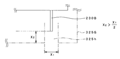
図8は、本発明の第4実施の形態を示す内視鏡装置における光学アダプタと、先端部本体との接続を示した接続構造図、図9は、図8のアノード側の端子130Aまたはカソード側の端子130Bの光学アダプタ内の配設位置を示した図である。
From the above, it is possible to realize an endoscope apparatus having an optical adapter with high reliability against applied static electricity.
(Fourth embodiment)
FIG. 8 is a connection structure diagram showing the connection between the optical adapter and the distal end body in the endoscope apparatus showing the fourth embodiment of the present invention, and FIG. 9 is the terminal 130A on the anode side or the cathode in FIG. It is the figure which showed the arrangement | positioning position in the optical adapter of the terminal 130B of the side.
この第4実施の形態の内視鏡装置の構成は、上記図7に示した第3実施の形態の内視鏡装置と比して、スイッチを用いないことにより静電気対策を施した点のみが異なる。よって、この相違点のみを説明し、第3実施の形態と同様の構成には同じ符号を付し、その説明は省略する。 The configuration of the endoscope apparatus of the fourth embodiment is only that the countermeasure against static electricity is taken by not using a switch as compared with the endoscope apparatus of the third embodiment shown in FIG. Different. Therefore, only this difference will be described, the same reference numerals are given to the same components as those in the third embodiment, and description thereof will be omitted.
図8に示すように、内視鏡装置201の内視鏡2の先端部本体222の先端に、後述する光学アダプタ325が装着された際、光学アダプタ325内に配設されたLED群130のアノード側の端子230A及びカソード側の端子230Bの接触端と電気的に接触する端子222A、222Bが先端部本体222の先端面222aから、突出してそれぞれ配設されている。
As shown in FIG. 8, when an
端子222A、222Bは、先端部本体222に光学アダプタ325が装着された際、光学アダプタ325のアノード側の端子230A及びカソード側の端子230Bの接触端と接触し、光学アダプタ325のアノード側の端子230A及びカソード側の端子230Bに、電源からの電力を供給する。
The terminals 222A and 222B come into contact with the contact ends of the anode-
内視鏡挿入部21の先端部本体122の先端に、視野方向及び視野角等の光学特性を変換する光学アダプタ325が着脱自在に装着される。光学アダプタ325は、例えば金属により構成された筒状の外装筐体325Gを有し、該外装筐体325G内の先端部に、複数のLED130dから構成されたLED群130が配設されている。
An
光学アダプタ325の先端部に、LED群130を配設することにより、内視鏡2の照明能力を向上させたり、個々のLED130dの配置位置を変えることにより、被検体への照明方向を変化させたりすることができる。
By disposing the
具体的には、光学アダプタ325の外装筐体325G内に、LED130dが、例えば4個直列に接続されたLED群130が配設されている。LED群130の両極端間である両極端間に、端子部であるアノード側の端子230A及びカソード側の端子230Bが接続されている。
Specifically, an
詳しくは、アノード側の端子230A及びカソード側の端子230Bの端子222A,222Bとの接触端が、光学アダプタ325の挿入部側の面325aよりも、上記外装筐体325Gの内部に凹んで位置するよう、アノード側の端子230A及びカソード側の端子230Bは、LED群130の両極端間に接続されている。
Specifically, the contact ends of the anode-
また、光学アダプタ325の面325aであって、端子222A、222Bに対向する位置に、光学アダプタ325の外装筐体325G内に配設されたアノード側の端子230A及びカソード側の端子230Bまで貫通する孔325hがそれぞれ形成されている。
Further, the surface 325a of the
尚、孔325hは、図9に示すように、孔325hの径をX1、光学アダプタ325の面325aからアノード側の端子230A及びカソード側の端子230Bの接触端までの深さをX2とすると、(X1・1/2)<X2となるようそれぞれ形成されている。
As shown in FIG. 9, the hole 325h has a diameter X1, and the depth from the surface 325a of the
次にこのように構成された内視鏡装置201における光学アダプタ325の作用について説明する。
先端部本体222に、光学アダプタ325が装着されると、先端部本体222の端子222A、222Bは、アノード側の端子230A、及びカソード側の端子230Bの接触端に接触する。その後、LED群130は発光する。
Next, the operation of the
When the
この際、先端部本体222の端子222A、222Bに静電気が発生していたとしても、アノード側の端子230A及びカソード側の端子230Bの接触端は、光学アダプタ325の面325aから(X1・1/2)<X2の条件を満たすX2だけ凹んで位置しているため、端子222A、222Bが、アノード側の端子230A及びカソード側の端子230Bの接触端に接触する前に、上記静電気は、光学アダプタ325の外装部材に飛ぶ。
At this time, even if static electricity is generated in the terminals 222A and 222B of the
よって、光学アダプタ325を先端部本体222に装着する際、端子部222Aまたは222Bに静電気の電圧が印加されたとしても、LED群130の両極端間には、静電気の電圧が印加されない。よって、LED群130を静電気から保護することができるため、LED群130が静電気破壊され難い。
Therefore, when the
さらに、先端部本体222に光学アダプタ325が装着されていない場合、アノード側の端子230A及びカソード側の端子230Bの接触端は、光学アダプタ325の面325aから(X1・1/2)<X2の条件を満たすX2だけ凹んで位置しているため、アノード側の端子230A及びカソード側の端子230Bの接触端の周辺の上記静電気は、光学アダプタ325の外装部材に飛ぶ。
Further, when the
よって、先端部本体222に光学アダプタ325が装着されていない場合においてもLED群130を静電気から保護することができるため、LED群130が静電気破壊され難い。
Therefore, since the
また、光学アダプタ325を取扱う際、取扱い者にアースを施す必要がないため、光学アダプタ325の取扱いが容易となる。
以上から、印加される静電気に対し、信頼性の高い光学アダプタが実現できる。
Further, when the
As described above, a highly reliable optical adapter can be realized with respect to applied static electricity.
(第5実施の形態)
図10は、本発明の第5実施の形態を示す内視鏡装置における光学アダプタと、先端部本体との接続を示した接続構造図である。
(Fifth embodiment)
FIG. 10 is a connection structure diagram showing the connection between the optical adapter and the distal end body in the endoscope apparatus showing the fifth embodiment of the present invention.
この第5実施の形態の内視鏡装置の構成は、上記図8、図9に示した第4実施の形態の内視鏡装置と比して、アノード側の端子及びカソード側の端子を光学アダプタに配設した保護部材内に配設した点のみが異なる。よって、この相違点のみを説明し、第4実施の形態と同様の構成には同じ符号を付し、その説明は省略する。 The configuration of the endoscope apparatus according to the fifth embodiment is such that the anode-side terminal and the cathode-side terminal are optically compared to the endoscope apparatus according to the fourth embodiment shown in FIGS. The only difference is that it is disposed in a protective member disposed on the adapter. Therefore, only this difference will be described, the same reference numerals are given to the same components as those in the fourth embodiment, and the description thereof will be omitted.
図10に示すように、内視鏡装置301の内視鏡2の先端部本体322の先端に、後述する光学アダプタ425が装着された際、光学アダプタ425に配設されたLED群130のアノード側の端子330A及びカソード側の端子330Bの接触端と電気的に接触する、アノード側の端子330A及びカソード側の端子330Bと同軸構造を有する端子322A、322Bがそれぞれ配設されている。
As shown in FIG. 10, when an
詳しくは、先端部本体322の先端面322aに、穴322hが2つ穿設されており、該2つの穴322hに、X4の外径を有する、例えば円形の筒(以下、円筒と称す)370がそれぞれ配設されており、さらに、円筒370の内部空間に、端子322A、端子322Bがそれぞれ配設されている。
Specifically, two holes 322h are formed in the distal end surface 322a of the distal end
端子322A、322Bは、先端部本体322の先端に光学アダプタ425が装着された際、光学アダプタ425のアノード側の端子330A及びカソード側の端子330Bの接触端と接触し、光学アダプタ425のアノード側の端子330A及びカソード側の端子330Bに、フレーム部4に配設された上記電源からの電力を供給する。
The
内視鏡挿入部21の先端部本体322の先端に、視野方向及び視野角等の光学特性を変換する光学アダプタ425が着脱自在に装着される。光学アダプタ425は、例えば金属により構成された筒状の外装筐体425Gを有している。
An
光学アダプタ425の先端部本体322に形成された穴322hにそれぞれ対向する位置に、円筒370の外径X4と同じかそれ以上の内径X3を有する、例えば金属により構成された保護部材である円筒340が、光学アダプタ425の外装筐体425Gの内部と外部と連通するよう、光学アダプタ425の外装筐体425Gにシールドされ、光学アダプタ425の外装筐体425Gの内部から挿入部21側に突出してそれぞれ配設されている。尚、この際、光学アダプタ425の外装筐体425Gと円筒340とは、同電位となっている。
A
光学アダプタ425が先端部本体322に装着された際、円筒340に内部に、先端部本体322の穴322hに配設された円筒370が挿入される。
When the
光学アダプタ425の外装筐体425G内の先端部に、LED130dから構成されたLED群130が配設されている。光学アダプタ425の先端部に、LED群130を配設することにより、内視鏡2の照明能力を向上させたり、個々のLED130dの配置位置を変えることにより、被検体への照明方向を変化させたりすることができる。
An
具体的には、光学アダプタ425の外装筐体425G内に、複数のLED130dが、例えば4個直列に接続されたLED群130が配設されている。LED群130の両極端間である両極端間に、円筒340内にそれぞれ配設された端子部であるアノード側の端子330A、及びカソード側の端子330Bが接続されている。
Specifically, an
詳しくは、アノード側の端子330A及びカソード側の端子330Bの端子322A,322Bとの接触端は、円筒340内であって、円筒340の表面である突出面340aよりも外装筐体425G側に凹んで位置している。
Specifically, the contact ends of the anode-
アノード側の端子330A、及びカソード側の端子330Bの端子322A,322Bとの接触端は、光学アダプタ425が先端部本体322に装着され、円筒340の内部に、円筒370が挿入された際、円筒370の内部に挿入される。
The contact ends of the anode-
次にこのように構成された内視鏡装置301における光学アダプタ425の作用について説明する。
先端部本体322に、光学アダプタ425が装着されると、光学アダプタ425に配設された円筒340は、先端部本体の穴322hに嵌入し、さらに光学アダプタ425に配設された円筒340の内部に、先端部本体322の円筒370が挿入される。
Next, the operation of the
When the
このことにより、円筒340の内部に配設されたアノード側の端子330A、及びカソード側の端子330Bの接触端は、円筒370の内部において、端子322A、322Bとそれぞれ接触する。よって、LED群130は発光する。
As a result, the contact ends of the anode-
この際、先端部本体322の端子322A、322B及び円筒370に静電気が発生していたとしても、アノード側の端子330A及びカソード側の端子330Bの接触端は、円筒340の突出面340aより凹んで位置しているため、端子322A、322Bが、アノード側の端子330A及びカソード側の端子330Bの接触端に接触する前に、上記静電気は、円筒340に飛ぶ。
At this time, even if static electricity is generated in the
よって、光学アダプタ425を先端部本体322に装着する際、端子部322Aまたは322Bに静電気の電圧が印加されたとしても、LED群130の両極端間には、静電気の電圧が印加されない。よって、LED群130を静電気から保護することができるため、LED群130が静電気破壊され難い。
Therefore, when the
さらに、先端部本体322に光学アダプタ425が装着されていない場合、アノード側の端子330A及びカソード側の端子330Bの接触端は、円筒340の突出面340aより凹んで位置しているため、アノード側の端子330A及びカソード側の端子330Bの接触端の周辺の上記静電気は、円筒340に飛ぶ。
Further, when the
よって、先端部本体322に光学アダプタ425が装着されていない場合においてもLED群130を静電気から保護することができるため、LED群130が静電気破壊され難い。
Therefore, since the
また、光学アダプタ425を取扱う際、取扱い者にアースを施す必要がないため、光学アダプタ425の取扱いが容易となる。
以上から、印加される静電気に対し、信頼性の高い光学アダプタが実現できる。
Further, when the
As described above, a highly reliable optical adapter can be realized with respect to applied static electricity.
尚、本実施の形態においては、保護部材である筒340、筒370は、円筒である示したが、これに限らず、筒340と筒370とが嵌合できる形状であれば、どのような形状であっても構わない。
In the present embodiment, the
また、上述した第1〜第5実施の形態においては、LED群130は、4個のLED130dから構成されると示したが、これに限らず1つまたは複数から構成されていても構わない。
In the first to fifth embodiments described above, the
さらに、上述した第1〜第5実施の形態においては、発光体は、LEDを例に挙げて説明したが、これに限らず、内視鏡の光源に用いられる小型のものであれば、どんな発光体であっても構わない。 Furthermore, in the first to fifth embodiments described above, the illuminant has been described by taking the LED as an example. It may be a light emitter.
[付記]
以上詳述した如く、本発明の実施形態によれば、以下の如き構成を得ることができる。即ち、
(1)外装筐体内に、
照明用の光源となる発光ダイオードと、
上記外装筐体内から外方に突出するよう上記発光ダイオードの両極端間に接続された2つの端子部と、
を有し、
上記発光ダイオードの両極端間に、上記発光ダイオードに静電気が印加されるのを防止する静電気保護手段を有することを特徴とする内視鏡用光学アダプタ。
[Appendix]
As described in detail above, according to the embodiment of the present invention, the following configuration can be obtained. That is,
(1) In the exterior housing,
A light emitting diode as a light source for illumination;
Two terminal portions connected between the extremes of the light emitting diode so as to protrude outward from the exterior casing;
Have
An optical adapter for an endoscope, comprising electrostatic protection means for preventing static electricity from being applied to the light emitting diode between both extremes of the light emitting diode.
(2)上記静電気保護手段は、ダイオードと、ツェナダイオードと、バリスタとのいずれかであることを特徴とする付記1に記載の内視鏡用光学アダプタ。
(2) The endoscope optical adapter according to
(3)上記静電気保護手段は、ダイオードと、ツェナダイオードと、バリスタとのいずれか2つの並列回路であることを特徴とする付記1に記載の内視鏡用光学アダプタ。
(3) The endoscope optical adapter according to
(4)上記静電気保護手段は、常閉型のスイッチであることを特徴とする付記1に記載の内視鏡用光学アダプタ。
(4) The endoscope optical adapter according to
(5)上記外装筐体は、金属により構成されており、上記2つの端子部は、上記外装筐体の表面に対して、上記外装筐体内に凹んで位置していることを特徴とする付記1〜3のいずれかに記載の内視鏡用光学アダプタ。 (5) The outer casing is made of metal, and the two terminal portions are recessed in the outer casing with respect to the surface of the outer casing. The optical adapter for endoscopes in any one of 1-3.
(6)上記外装筐体に、該外装筐体の内部と外部とを連通する筒状の保護部材が、上記外装筐体内から外方に突出するよう接続されており、
上記2つの端子部は、上記突出した保護部材の表面に対して、上記保護部材内に凹んで位置していることを特徴とする付記1〜3のいずれかに記載の内視鏡用光学アダプタ。
(6) A cylindrical protective member that communicates the inside and outside of the exterior casing is connected to the exterior casing so as to protrude outward from the interior of the exterior casing,
The optical adapter for an endoscope according to any one of
(7)上記保護部材は、金属により構成されていることを特徴とする付記6に記載の内視鏡用光学アダプタ。 (7) The endoscope optical adapter according to appendix 6, wherein the protective member is made of metal.
(8)付記1〜7に記載の内視鏡用光学アダプタと、
上記内視鏡用光学アダプタに装着した際、上記内視鏡用光学アダプタの上記2つの端子部とそれぞれ電気的に接触する2つの端子部を有する内視鏡挿入部と、
を有することを特徴とする内視鏡装置。
(8) The endoscope optical adapter according to
An endoscope insertion portion having two terminal portions that are in electrical contact with the two terminal portions of the endoscope optical adapter when mounted on the endoscope optical adapter;
An endoscope apparatus characterized by comprising:
(9)上記内視鏡挿入部は、付記4に記載の上記内視鏡用光学アダプタに装着した際、上記常閉型のスイッチを開にする突起部を先端に有することを特徴とする付記8に記載の内視鏡装置。
(9) The supplementary note, wherein the endoscope insertion portion has a protrusion at the tip for opening the normally-closed switch when attached to the endoscope optical adapter according to
(10)上記内視鏡挿入部は、付記5に記載の上記内視鏡用光学アダプタに装着した際、上記外装筐体内に凹んで位置している上記2つの端子部と、上記外装筐体内においてそれぞれ電気的に接触する2つの端子部を有することを特徴とする付記8に記載の内視鏡装置。 (10) When the endoscope insertion portion is attached to the endoscope optical adapter according to appendix 5, the two terminal portions that are recessed in the exterior housing and the interior of the exterior housing The endoscope apparatus according to appendix 8, further comprising two terminal portions that are in electrical contact with each other.
(11)上記内視鏡挿入部は、請求項6に記載の上記内視鏡用光学アダプタに装着した際、上記保護部材内に凹んで位置している上記2つの端子部と、上記保護部材内においてそれぞれ電気的に接触する2つの端子部を有することを特徴とする付記8に記載の内視鏡装置。 (11) When the endoscope insertion portion is attached to the endoscope optical adapter according to claim 6, the two terminal portions that are recessed in the protection member and the protection member The endoscope apparatus according to appendix 8, which has two terminal portions that are in electrical contact with each other.
1…内視鏡装置
21…内視鏡挿入部
25…光学アダプタ
25G…外装筐体
101…内視鏡装置
122A…挿入部側端子
122B…挿入部側端子
122T…突起ピン
125…光学アダプタ
125G…外装筐体
130A…アノード側の端子
130B…カソード側の端子
130d…発光ダイオード
160…ダイオード
201…内視鏡装置
222A…挿入部側端子
222B…挿入部側端子
225…光学アダプタ
225G…外装筐体
230A…アノード側の端子
230B…カソード側の端子
260…ツェナダイオード
301…内視鏡装置
322A…挿入部側端子
322B…挿入部側端子
325…光学アダプタ
325a…外装筐体表面
325G…外装筐体
330A…アノード側の端子
330B…カソード側の端子
340…円筒
340a…円筒表面
360…バリスタ
400…並列回路
425…光学アダプタ
425G…外装筐体
460…常閉型スイッチ
代理人 弁理士 伊藤 進
DESCRIPTION OF
Claims (5)
外装筐体と、照明用の光源となる発光体と、前記外装筐体内から外方に突出するよう前記発光体の両極端間に接続された2つの端子からなる第1の端子部と、前記2つの端子の間に設けられ、前記内視鏡挿入部の先端部に設けられた第2の端子部が前記第1の端子部に接触していない場合において短絡状態を維持し、かつ、前記第2の端子部が前記第1の端子部に接触している場合において開放状態になることにより前記発光体の両極端間と前記他の端子とを電気的に導通させることができるように構成されたスイッチ部と、を備えた内視鏡用光学アダプタと、
を有し、
前記内視鏡挿入部は、前記内視鏡用光学アダプタに装着した際に前記スイッチ部に接触して前記スイッチ部を開放状態にする突出部を備えたことを特徴とする内視鏡装置。 An endoscope insertion part;
And the outer casing, a light emitting element as a light source for illumination, a first terminal portion consisting of two terminals connected between the extremes of the luminous body so as to protrude outwardly from the outer housing, wherein A second terminal portion provided between two terminals, provided at a distal end portion of the endoscope insertion portion, maintains a short circuit state when not in contact with the first terminal portion; and When the second terminal portion is in contact with the first terminal portion, the second terminal portion is configured to be in an open state so that the extremes of the light emitter can be electrically connected to the other terminal. An optical adapter for an endoscope comprising a switch unit ;
Have
The endoscope insertion portion, the endoscope apparatus characterized by in contact with said switch portion when mounted on the optical adapter for the endoscope with a protruding portion to open the switch portion.
前記2つの端子は、前記突出した保護部材の表面に対して、前記保護部材内に凹んで位置していることを特徴とする請求項1又は2に記載の内視鏡装置。 A cylindrical protective member that communicates the inside and outside of the exterior housing is connected to the exterior housing so as to protrude outward from the interior of the exterior housing,
It said two jacks, relative to the surface of the protective member in the projecting endoscope apparatus according to claim 1 or 2, characterized in that positioned recessed in said protective member.
Priority Applications (2)
| Application Number | Priority Date | Filing Date | Title |
|---|---|---|---|
| JP2004152467A JP4603291B2 (en) | 2004-05-21 | 2004-05-21 | Endoscope device |
| US11/129,792 US7637866B2 (en) | 2004-05-21 | 2005-05-16 | Optical adaptor for endoscope and endoscope apparatus |
Applications Claiming Priority (1)
| Application Number | Priority Date | Filing Date | Title |
|---|---|---|---|
| JP2004152467A JP4603291B2 (en) | 2004-05-21 | 2004-05-21 | Endoscope device |
Publications (3)
| Publication Number | Publication Date |
|---|---|
| JP2005329173A JP2005329173A (en) | 2005-12-02 |
| JP2005329173A5 JP2005329173A5 (en) | 2007-06-07 |
| JP4603291B2 true JP4603291B2 (en) | 2010-12-22 |
Family
ID=35484189
Family Applications (1)
| Application Number | Title | Priority Date | Filing Date |
|---|---|---|---|
| JP2004152467A Expired - Fee Related JP4603291B2 (en) | 2004-05-21 | 2004-05-21 | Endoscope device |
Country Status (2)
| Country | Link |
|---|---|
| US (1) | US7637866B2 (en) |
| JP (1) | JP4603291B2 (en) |
Families Citing this family (12)
| Publication number | Priority date | Publication date | Assignee | Title |
|---|---|---|---|---|
| JP4917436B2 (en) * | 2004-10-25 | 2012-04-18 | オリンパス株式会社 | Endoscope device |
| US20070185379A1 (en) * | 2005-01-10 | 2007-08-09 | Perceptron, Inc. | Modular remote inspection device with digital imager |
| US8617059B2 (en) * | 2005-05-27 | 2013-12-31 | Olympus Corporation | Endoscopic apparatus and endoscope adapter |
| JP4804062B2 (en) * | 2005-07-29 | 2011-10-26 | オリンパス株式会社 | Endoscope system |
| JP4934299B2 (en) * | 2005-08-10 | 2012-05-16 | オリンパス株式会社 | Endoscope device |
| US20070039077A1 (en) * | 2005-08-10 | 2007-02-15 | Pentax Corporation | Endoscope |
| JP2007130085A (en) * | 2005-11-08 | 2007-05-31 | Olympus Corp | Electronic endoscope |
| DE102007015492B4 (en) * | 2007-01-30 | 2011-03-24 | Fraunhofer-Gesellschaft zur Förderung der angewandten Forschung e.V. | Illumination device for an image capture device at the distal end of an endoscope |
| JP4986646B2 (en) * | 2007-02-05 | 2012-07-25 | オリンパス株式会社 | Endoscope device |
| JP5139742B2 (en) | 2007-08-03 | 2013-02-06 | オリンパスメディカルシステムズ株式会社 | Endoscope |
| US8900134B2 (en) * | 2008-02-12 | 2014-12-02 | Olympus Corporation | Endoscope apparatus and method of controlling endoscope apparatus |
| DE102009041151B4 (en) * | 2009-09-14 | 2019-06-13 | Dürr Dental SE | Handpiece camera |
Citations (6)
| Publication number | Priority date | Publication date | Assignee | Title |
|---|---|---|---|---|
| JPS6147920A (en) * | 1984-08-15 | 1986-03-08 | Olympus Optical Co Ltd | Endoscope |
| JPH0595048U (en) * | 1992-01-14 | 1993-12-24 | ヤマハ株式会社 | Integrated circuit |
| JPH11233200A (en) * | 1998-02-18 | 1999-08-27 | Toray Ind Inc | Connector |
| JPH11253402A (en) * | 1998-03-10 | 1999-09-21 | Olympus Optical Co Ltd | Endoscope |
| JP2000228254A (en) * | 1999-02-05 | 2000-08-15 | Victor Co Of Japan Ltd | Electronic apparatus having input/output terminal, and input/output terminal |
| JP2002124602A (en) * | 2000-10-16 | 2002-04-26 | Mitsubishi Electric Corp | Semiconductor device |
Family Cites Families (18)
| Publication number | Priority date | Publication date | Assignee | Title |
|---|---|---|---|---|
| JPS5144520Y2 (en) * | 1972-09-26 | 1976-10-28 | ||
| US6054716A (en) * | 1997-01-10 | 2000-04-25 | Rohm Co., Ltd. | Semiconductor light emitting device having a protecting device |
| US6095970A (en) * | 1997-02-19 | 2000-08-01 | Asahi Kogaku Kogyo Kabushiki Kaisha | Endoscope |
| JPH11103097A (en) * | 1997-07-30 | 1999-04-13 | Rohm Co Ltd | Semiconductor light emitting element |
| US6164208A (en) * | 1998-07-14 | 2000-12-26 | Chung Shan Institute Of Science & Technology | Igniter for vehicle airbag inflator |
| US6348035B1 (en) * | 1998-09-09 | 2002-02-19 | Asahi Kogaku Kogyo Kabushiki Kaisha | Connection system for electronic endoscope |
| JP3600735B2 (en) | 1998-09-09 | 2004-12-15 | ペンタックス株式会社 | Electronic endoscope connection system |
| US6796939B1 (en) * | 1999-08-26 | 2004-09-28 | Olympus Corporation | Electronic endoscope |
| KR100628254B1 (en) * | 2000-04-12 | 2006-09-27 | 엘지.필립스 엘시디 주식회사 | Liquid Crystal Display |
| JP2002095624A (en) | 2000-09-26 | 2002-04-02 | Fuji Photo Film Co Ltd | Fluorescence endoscope system |
| US6414779B1 (en) * | 2000-11-30 | 2002-07-02 | Opeical Biopsy Technologies, Inc. | Integrated angled-dual-axis confocal scanning endoscopes |
| DE10121450A1 (en) * | 2001-04-27 | 2002-11-21 | Storz Endoskop Gmbh Schaffhaus | Optical instrument, in particular an endoscope, with an exchangeable head |
| US20030075987A1 (en) * | 2001-10-23 | 2003-04-24 | Shields Ronald Allen | Airbag initiator safety mechanism |
| TW545698U (en) * | 2001-12-28 | 2003-08-01 | United Epitaxy Co Ltd | LED packaging structure with a static charge protecting device |
| TW535307B (en) * | 2002-03-04 | 2003-06-01 | United Epitaxy Co Ltd | Package of light emitting diode with protective diode |
| JP2003279862A (en) * | 2002-03-25 | 2003-10-02 | Machida Endscope Co Ltd | Omnidirectional endoscopic device |
| JP2004148028A (en) * | 2002-11-01 | 2004-05-27 | Fuji Photo Optical Co Ltd | Electronic endoscope apparatus |
| JP4277256B2 (en) * | 2003-02-24 | 2009-06-10 | フジノン株式会社 | Endoscope light source device |
-
2004
- 2004-05-21 JP JP2004152467A patent/JP4603291B2/en not_active Expired - Fee Related
-
2005
- 2005-05-16 US US11/129,792 patent/US7637866B2/en active Active
Patent Citations (6)
| Publication number | Priority date | Publication date | Assignee | Title |
|---|---|---|---|---|
| JPS6147920A (en) * | 1984-08-15 | 1986-03-08 | Olympus Optical Co Ltd | Endoscope |
| JPH0595048U (en) * | 1992-01-14 | 1993-12-24 | ヤマハ株式会社 | Integrated circuit |
| JPH11233200A (en) * | 1998-02-18 | 1999-08-27 | Toray Ind Inc | Connector |
| JPH11253402A (en) * | 1998-03-10 | 1999-09-21 | Olympus Optical Co Ltd | Endoscope |
| JP2000228254A (en) * | 1999-02-05 | 2000-08-15 | Victor Co Of Japan Ltd | Electronic apparatus having input/output terminal, and input/output terminal |
| JP2002124602A (en) * | 2000-10-16 | 2002-04-26 | Mitsubishi Electric Corp | Semiconductor device |
Also Published As
| Publication number | Publication date |
|---|---|
| US7637866B2 (en) | 2009-12-29 |
| JP2005329173A (en) | 2005-12-02 |
| US20060069309A1 (en) | 2006-03-30 |
Similar Documents
| Publication | Publication Date | Title |
|---|---|---|
| US7637866B2 (en) | Optical adaptor for endoscope and endoscope apparatus | |
| US9345384B2 (en) | Endoscope having breakable portions for preventing damage to the imaging unit | |
| US20080208002A1 (en) | Endoscope | |
| JP4505222B2 (en) | Endoscope system with solid light source | |
| US9125553B2 (en) | Endoscope with electrical conductive portion | |
| JP2008510193A (en) | Plug-in unit for endoscope | |
| US20210338057A1 (en) | Endoscope distal end portion and endoscope | |
| JP4390511B2 (en) | Electronic endoscope device | |
| US20210307590A1 (en) | Endoscope distal end structure and endoscope | |
| US20240115114A1 (en) | Illuminator circuit board assembly for an endoscope | |
| JP2005329173A5 (en) | ||
| EP3426129A2 (en) | Illuminator circuit board assembly for an endoscope | |
| WO2020170340A1 (en) | Endoscope distal end structure and endoscope | |
| JP5342825B2 (en) | Endoscope and endoscope system | |
| JP2017148298A (en) | Endoscope | |
| JP4313627B2 (en) | Endoscope connector device | |
| JP3708392B2 (en) | Endoscope battery-type light source device | |
| US20170325665A1 (en) | Illuminator Circuit Board Assembly for An Endoscope | |
| WO2019116637A1 (en) | Endoscope, distal end cover, and endoscope system | |
| JP2001149306A (en) | Endoscope | |
| WO2021176736A1 (en) | Distal end portion of endoscope, distal end frame, endoscope, and conduction confirming method | |
| JP2010046282A (en) | Endoscope distal end tip, endoscope and endoscopic system | |
| JP5131694B2 (en) | Endoscope battery box | |
| WO2020003474A1 (en) | Endoscope tip end structure and endoscope | |
| JP2010227156A (en) | Endoscope |
Legal Events
| Date | Code | Title | Description |
|---|---|---|---|
| A521 | Written amendment |
Free format text: JAPANESE INTERMEDIATE CODE: A523 Effective date: 20070418 |
|
| A621 | Written request for application examination |
Free format text: JAPANESE INTERMEDIATE CODE: A621 Effective date: 20070418 |
|
| A977 | Report on retrieval |
Free format text: JAPANESE INTERMEDIATE CODE: A971007 Effective date: 20100402 |
|
| A131 | Notification of reasons for refusal |
Free format text: JAPANESE INTERMEDIATE CODE: A131 Effective date: 20100713 |
|
| A521 | Written amendment |
Free format text: JAPANESE INTERMEDIATE CODE: A523 Effective date: 20100820 |
|
| TRDD | Decision of grant or rejection written | ||
| A01 | Written decision to grant a patent or to grant a registration (utility model) |
Free format text: JAPANESE INTERMEDIATE CODE: A01 Effective date: 20100907 |
|
| A01 | Written decision to grant a patent or to grant a registration (utility model) |
Free format text: JAPANESE INTERMEDIATE CODE: A01 |
|
| A61 | First payment of annual fees (during grant procedure) |
Free format text: JAPANESE INTERMEDIATE CODE: A61 Effective date: 20101001 |
|
| FPAY | Renewal fee payment (event date is renewal date of database) |
Free format text: PAYMENT UNTIL: 20131008 Year of fee payment: 3 |
|
| FPAY | Renewal fee payment (event date is renewal date of database) |
Free format text: PAYMENT UNTIL: 20131008 Year of fee payment: 3 |
|
| S531 | Written request for registration of change of domicile |
Free format text: JAPANESE INTERMEDIATE CODE: R313531 |
|
| R350 | Written notification of registration of transfer |
Free format text: JAPANESE INTERMEDIATE CODE: R350 |
|
| LAPS | Cancellation because of no payment of annual fees |