JP4601784B2 - Rigid core with two parts for tire production - Google Patents
Rigid core with two parts for tire production Download PDFInfo
- Publication number
- JP4601784B2 JP4601784B2 JP2000240295A JP2000240295A JP4601784B2 JP 4601784 B2 JP4601784 B2 JP 4601784B2 JP 2000240295 A JP2000240295 A JP 2000240295A JP 2000240295 A JP2000240295 A JP 2000240295A JP 4601784 B2 JP4601784 B2 JP 4601784B2
- Authority
- JP
- Japan
- Prior art keywords
- core
- rim
- piece
- tire
- main
- Prior art date
- Legal status (The legal status is an assumption and is not a legal conclusion. Google has not performed a legal analysis and makes no representation as to the accuracy of the status listed.)
- Expired - Fee Related
Links
Images


Classifications
-
- B—PERFORMING OPERATIONS; TRANSPORTING
- B29—WORKING OF PLASTICS; WORKING OF SUBSTANCES IN A PLASTIC STATE IN GENERAL
- B29D—PRODUCING PARTICULAR ARTICLES FROM PLASTICS OR FROM SUBSTANCES IN A PLASTIC STATE
- B29D30/00—Producing pneumatic or solid tyres or parts thereof
- B29D30/06—Pneumatic tyres or parts thereof (e.g. produced by casting, moulding, compression moulding, injection moulding, centrifugal casting)
- B29D30/08—Building tyres
- B29D30/10—Building tyres on round cores, i.e. the shape of the core is approximately identical with the shape of the completed tyre
- B29D30/12—Cores
-
- B—PERFORMING OPERATIONS; TRANSPORTING
- B29—WORKING OF PLASTICS; WORKING OF SUBSTANCES IN A PLASTIC STATE IN GENERAL
- B29C—SHAPING OR JOINING OF PLASTICS; SHAPING OF MATERIAL IN A PLASTIC STATE, NOT OTHERWISE PROVIDED FOR; AFTER-TREATMENT OF THE SHAPED PRODUCTS, e.g. REPAIRING
- B29C35/00—Heating, cooling or curing, e.g. crosslinking or vulcanising; Apparatus therefor
- B29C35/02—Heating or curing, e.g. crosslinking or vulcanizing during moulding, e.g. in a mould
- B29C2035/0211—Heating or curing, e.g. crosslinking or vulcanizing during moulding, e.g. in a mould resistance heating
-
- B—PERFORMING OPERATIONS; TRANSPORTING
- B29—WORKING OF PLASTICS; WORKING OF SUBSTANCES IN A PLASTIC STATE IN GENERAL
- B29C—SHAPING OR JOINING OF PLASTICS; SHAPING OF MATERIAL IN A PLASTIC STATE, NOT OTHERWISE PROVIDED FOR; AFTER-TREATMENT OF THE SHAPED PRODUCTS, e.g. REPAIRING
- B29C33/00—Moulds or cores; Details thereof or accessories therefor
- B29C33/02—Moulds or cores; Details thereof or accessories therefor with incorporated heating or cooling means
Abstract
Description
【0001】
【発明の属する技術分野】
本発明はタイヤの製造法に関するものである。
本発明は特に、タイヤ製造時の支持体の役目とタイヤの内側空洞部の表面成形手段の役目をする実質的に剛体のコアに関するものである。
【0002】
【従来技術】
欧州特許第 0,666,165号に開示のタイヤ製造機ではタイヤ製造時の支持体の役目をする上記形式のコアが用いられている。このコアはタイヤ製造後に取り外され、次のタイヤの製造時に再度取り付けられて支持体の役目をする。このコアは取付け/取外しサイクルに何度も耐えなければならず、高い幾何学的品質を保証できるだけの強度を有していなければならず、さらに、何度使用した場合でもその間コアが高い品質を維持できなければならない。この欧州特許第 0,666,165号は、コアの必須の構成要素である各種断片を一体化するための部材としてリムを使用することが提案されている。
【0003】
問題は、コアの取付け/取外しが容易にでき、また、タイヤ製造機でのステーションからステーションへのコアの運搬を複雑にし過ぎずに、十分な強度のコアをいかに設計するかにある。さらに、このコアは製造すべき各種のタイヤの形状に正確に一致しなければならない。また、製造機械をできるだけ汎用なものにするためには、コアをある程度標準化するのが望ましく、できるだけ均一かつ迅速に加硫するためにはコアを通して加硫すべきタイヤに熱を供給できるのが便利である。また、この種のコアはできるだけ堅固でかつ加硫すべきタイヤへの熱の伝達に優れ、ステーションからステーションへの運搬の加速度および速度を高くするために、できるだけ軽量化するのが好ましい。
【0004】
この剛性コアはタイヤの内側表面の製造型の少なくとも一部を規定するためのものである。このコアは、ビードの内側空間を通ってタイヤの内部から抜き取ることができるようにするために、複数の断片で構成されている。このコアは横方向面が接触するように互いに並んで配置された周方向に互いに隣接した複数の断片からなる。「横方向面」とはコアの一方の側から他方の側へ延びる面を意味する。図示した実施例では、これらの面はコアの軸線に対して平行な面である。なお、本発明がこれらの特徴に限定されるものではない。
【0005】
【発明が解決しようとする課題】
本発明はこれらの各断片をそれぞれの要求を満たす2つの異なる部分すなわち接触部分と、接触部分と一体化される主要部分とで製造することを提案する。
【0006】
【課題を解決するための手段】
主要部分の主要な役目はタイヤの内側表面を成形することにある。すなわち、主要部分は製造型の役目をし、タイヤの内側表面を成形する。接触部分の主要な役目はコアを構成する各断片を一体化するための部材に各断片を固定することにある。各断片は各種断片を一体化するための部材に固定するための部分を有している。
【0007】
接触部分は各断片の放射方向内側端部に配置されている。接触部分は取付け/取外しサイクルに何度も耐える特性から選択された第1の材料で作られている。接触部分はリムやグリッパ、コアを利用する各ステーションに設けられたその他の処理部材によって各断片を把持するのが最適化できるような設計になっている。
各断片はさらに、接触部分と一体化される主要部分を有している。この主要部分は主として成形性および熱伝導性が良好であることから選択される第1の材料とは異なる第2の材料で作られている。主要部分は接触部分と一体化されて機能上取外すことができない。主要部分は各タイヤの寸法に独特な部品であり、タイヤの成形および加硫を最適化でき、経済的になるように製造されるが、接触部分は複数の異なるタイヤに対して同一図および同一概念で製造することができる。
【0008】
【発明の実施の形態】
加硫および成形によって与えられる正確な形状にタイヤの生ブランクを製造するのは極めて難しいということは理解できよう。特に、ビードの下側部分は最終断面に近似した断面にしかできない。タイヤの生ブランクの状態では、ビードの放射方向下側部分は成形後に得られる高さより放射方向の低い高さに配置される。その結果、欧州特許第0,242,840号に記載の金型を閉じた時に、シェルの延長部がタイヤビードの放射方向内側部分をわずかに擦ることがある。まだ生のビードをシェルの延長部が擦った場合に、タイヤブランクから取られたゴムの小さい破片が運ばれることがある。このゴムの小さい破片は金型の内部へ押し戻されて、失われる。その結果、このゴムの破片によって金型および/またはプレスが汚染されされるため、金型および/またはプレスの2回の洗浄操作の間に製造時間ロスする。さらに、金型の内部に押し戻されたこのゴムの小さい破片が金型キャビティーに残った場合には、硬化後のタイヤの外観に欠陥が生じる危険がある。
【0009】
本発明の特徴により、成形機能の全てを主要部分に割り当て、接触部分の表面は、この変形例では成形機能に関与しないようにすることでこの問題は解決される。この場合、中間面はコアの成形表面の延長部上に最小半径へ向かって(すなわち内部へ向かって)放射方向に延びている。この中間面は成形部分の形状および向きに依存し、回転軸線に対して直角な面内にあるか、非常に大きい角度の円錐台を形成する。従って、ビードの放射方向最下側部分が完成したタイヤの放射方向高さよりも低くなっても、型閉め移動で生じるバリは単に挟まれるだけで、剪断されず、タイヤに固定されたまま残る。これによって上記の欠点は避けられる。
【0010】
また、接触部分と主要部分との間の接合線を中間面内に配置することで接触部分と主要部分との間のゴムがクリープし、それによってタイヤビードの内側表面にバリが生じるのを防ぐのが好ましい。この配置の別の利点は接触部分が成形機能を持たないため、接触部分(特に全断片の全ての接触部分)が必ずしも連続した表面を形成する必要がない点にある。
【0011】
本発明の別の観点から、断片間にバリが発生するのを防止し、一連の取外し/取付け操作に耐えることができる極めて堅固なコアの構造を得るために、タイヤの内側表面用の製造型の少なくとも一部を規定する剛性コアにおいて、剛性コアが横方向面が接触するように互いに並んで配置された周方向に互いに隣接する複数の断片からなり、少なくとも1つの断片の横方向面はコアの外側へ向かって放射状に収斂しており、各断片は各種断片を一体化するための部材を有する接触部分を有し、この接触部分は各断片の放射方向内側端部に配置され且つ主として第1の材料で作られており、さらに、接触部分と一体な主要部分を有し、この主要部分は主として第1材料とは異なる第2の材料で作られ且つ接触部分と一体であり、ゴムの加硫温度で主要部分が隣接断片の間へ突出しない状態で遊びゼロで互いに接触し且つ均一な成形表面を形成し、加硫温度以下の温度では主要部分の間に遊びできるように主要部分、接触部分および主要部分と接触部分との間の接合部の寸法および構成が決定されているコアが提供される。
【0012】
本発明のさらに別の観点から、熱交換をよくするために、タイヤの内側表面用の製造型の少なくとも一部を規定する剛性コアにおいて、横方向面が接触するように互いに並んで配置された周方向に互いに隣接した複数の断片からなり、少なくとも1つの断片の横方向面はコアの外側へ放射方向に収斂しており、各断片は各種断片を一体化するための部材に接触する接触部分を有し、この接触部分は各断片の放射方向内側端部に配置され、さらに、接触部分と一体化された主要部分を有し、この主要部分は主として熱伝導性の良好な流動性のある材料で作られており、各断片には熱伝導を良くするための電気抵抗器が少なくとも一つ一体成形されていることを特徴とするコアが提供される。
本発明の上記以外の特徴および利点は添付図面を参照した以下の説明からより良く理解できよう。
【0013】
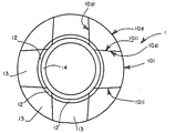
図1と図2(a)、(b)は本発明の第1実施例の剛性コア1を示している。周方向に互いに隣接して並んで配置された複数の金型断片(fraction、以下、断片という)10d、10iはその横方向面10d1、10i1を介して互いに接触している。少なくとも1つの断片10iの横方向面10i1はコアの外側へ向かって拡大しているので、断片を内部から放射方向に移動させればコアは外すことができる。本発明のコアは欧州特許第0,242,840号と同様に2つの断片モデル(すなわち横方向面10dlがコアの外部へ向かって末広がりに拡大している断片10dと横方向面10i1がコアの外部ヘ向かって収斂するいわゆる「逆形」の断片10i)とからなる。以下の説明では、収斂するか、末広がりに拡大するかが特に重要でない場合には、記号iまたはdを省略して単に「断片10」とよぶことにする。
【0014】
各断片10はリム14と係合する接触部分12を有している。この接触部分12は各断片の放射方向内側端部に配置されている。図1に示すように、リム14は周方向に連続し、一方、各接触部分12は断片10の一部であるので円の一部である。接触部分12は取付け/取外しサイクルに何度も耐えることを主たる特性とした第1の材料で作られている。各断片10はこの接触部分12と一体な主要部分13を有している。この主要部分13の主要な役目はタイヤ製造時にタイヤ表面を規定することにある。主要部分13は成形性に優れ、熱伝導性が良く、軽量であることを主たる特性とした第2の材料で作られており、接触部分12と一体で、機能上取り外すことができない。
【0015】
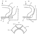
図2(b)にはコア1と協働して金型キャビティーを規定するシェル15が示されている。一つのサイドウォールに対して1つのシェルがあり、トレッドを成形するための手段(図示せず)があるということは理解できよう。タイヤのサイドウォールの外側表面を成形するためのシェル15はその放射方向内側部分にコアの放射方向内側表面の下側上を摺動する延長部140を有している。これによって各シェルがその閉位置に達する前に成形空間が完全に分離され、閉じられる。これは本発明の最も簡単な実施例である。この場合、接触部分12を主要部分13から離す線L1がタイヤの金型キャビティー内にあるので、接触部分12はタイヤの成形に関与するということは理解できよう。
【0016】
既に説明したように、硬化時には(ゴムの膨張により)金型キャビティー内の圧力が上昇し、しかも、適当な保持手段がないため、末広がりに拡大する断面10dでは逆形の断片10iが内部へ向かって移動する(図2(c))のを防止することができない。すなわち、これらの逆形の断片10iは末広がりに拡大する断面によって妨げられずに放射方向移動して加硫済みタイヤの内部から取り外すことができるように設計されている。軸方向両側(図2(b)では片側のみを示す)の全ての断片10の放射方向内側表面の下側で摺動する延長部140の別の役目は、硬化中のタイヤの昇圧の影響で逆形の断片10iが内部へ向かって移動するのを防止することにある。この摺動によって延長部140と接触する断片のこの部分は接触部分12の一部となり、コアを極めて堅固なものにする。各図では延長部140と接触部分12との間の放射方向間隙およびリムと接触部分との放射方向間隙は強調されており、比率は考慮していないということは理解できよう。
【0017】
図3は本発明の第2実施例のコア2を示している。この断片20は接触部分22と主要部分23とからなり、接触部分22はリム24に取付けられている。コア2はシェル25(各サイドウォールに付き1つのシェル)と協働して金型キャビティーを規定する。中間面21は断片20の成形表面のまっすぐな延長部に放射方向内側へ向かって真っ直ぐに配置されていることがわかる。この中間面21は断片20の成形部分の放射方向下側にあり、回転軸線に対して直角な面内にあるか(図示したように)、大きく開いた非常に大きな角度の円錐形をしている。従って、生ゴムが延長部140によって押されて生タイヤブランクの周りを閉じる移動の間にバリの形成が始まると、このバリは点P1と点P2との間にはさまれて、図2(a)の点P1と点P2との間とは違って剪断されることがない。挿まれたバリはタイヤに固定されたまま維持されるということは明らかである。
【0018】
接触部分22と主要部分23との間の接合線L2は中間面21内にあって接触部分と主要部分との間でゴムをクリープさせて、タイヤビードの内側表面上にバリが生じるのを防ぐのが好ましい。
【0019】
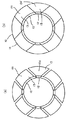
タイヤの加硫にコアを用いる場合には、大きな成形バリが発生するのを防止するために、各断片の間に存在する遊びを極めて小さくしなくてはならないということは理解できよう。さらに、この種のコアは膨張係数の異なる部分(接触部分は鋼、主要部分はアルミニウム)を有するので、タイヤ製造時に生じる熱サイクルをに合わせるのが好ましい。少なくとも加硫時にはコアは約150℃の温度で使用され、生タイヤブランクの製造時には100℃以下の温度が用いられる。こうした熱サイクルに合わせるために、主要部分13とその接触部分12への接合部(図4(a)、(b))の寸法は、生タイヤの取付けにコアを用いた時に、各断片10iと各断片10dとの間に遊びが加硫に必要な温度まで上昇した時(図4(b)の加硫温度)にのみ閉じるように決める(図4(a)では加硫温度以下の温度での各断片10間の遊びが強調されている)。そうすることよって主要部分が熱膨張によって大きくなり、末広がりに拡大した断片10iが放射方向外側へ押し出されることはない。また、断片10を互いに接合する接合手段(接触部分およびリム)の劣化が防止される。
【0020】
これら全ての実施例では、断片10、20がその内側部分に放射方向に配置される接触部分12、22を常に有している。断片10、20は軽合金で成形された主要部分13、23を有している。
図5(a)、(b)は接触部分32にネジ36によって固定された主要部分33を示している。ネジ36は断片30の横方向両側にあり、断片の周方向のほぼ中央部分に配置されている。この連結部は接触部分32と主要部分33との間のほぼ中心にあるので、接触部分32、主要部分33あるいは接触部分と主要部分33との間の接合ネジ36を損傷しないで主要部分は接触部分より大きく膨張することができる。
【0021】
コアの取付け/取外し操作を行なう毎に接触支持面には著しく大きな力が加わるということは理解できよう。この部分はそれに適した材料を選択して、非常に強くする。さらに、コア取付け/取外し操作時に毎回多くの衝撃、打撃および摩擦を受けるこの領域の耐久性を確実にするために適当な表面処理を行うことができる。
【0022】
接触部分が成形部分である(図6(a)、(b))か、否か(図6(c)、(d)、(e))に応じて考えられる別の相違点を検討してみよう。図6(a)に示すように、接触部分42の領域425はビードBの反対側で放射方向に延び、接触部分42と主要部分43とを分離する接合線L4はタイヤのビードBの内側表面上に現れる。この場合には少なくともタイヤ成形部分に全ての接触部分が周方向で連続した面を形成する必要があることは明らかである。これは、成形表面が主要部分53(図6(d))全体にある場合は必要ではない。図6(c)に示すように、接触部分52と主要部分53とを分離する接合線L5は中間面51上に現れる。タイヤのビードBの内側面全体が主要部分53によって成形される。この場合は図6(c)の円筒形の面P3がわずかに截頭台形であるのが有利である。
【0023】
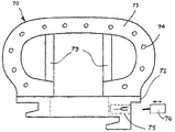
図7は極めて大型の断片70の主要部分の詳細図である。主要部分73は中心部分がほぼ放射方向に配置された柱70によって補強され、この柱はこの主要部分の内側部分を放射方向最外側位置にあるアーチに連結している。
接触部分は一般に鋼等の金属を用いて製造される。この接触部分はコアの取付け、取扱い時に必要な所望の全ての支持面および形状が得られるように鋼を切削加工して作られる。主要部分は一般にアルミニウム合金等の鋳造軽合金を用いて製造される。各主要部分の放射方向外側ドームを形成する壁の中には電気抵抗器を成形(埋め込む)することができる。
【0024】
図7は電気抵抗器74を示している。12個の抵抗器74を有する放射方向断面は湾曲し、周方向を向いた各断片を通るようになっている。実際には熱伝導性の良好な流動性のある材料を用いて各主要部分の放射方向外側ドームを形成する壁を成形し、その内側に1つの断片当たり少なくとも1つの電気抵抗器を埋め込んで成形する。変形例では、熱の伝導を良くするのに適した方法で抵抗器を切削加工した凹部内に固定するか、壁の内側表面に固定するができる。コアはタイヤ製造機内でステーションからステーションへ運搬できなければならないので、コネクタ75を設けて、グリッパが加硫ステーションに接近した時に別のコネクタ76を介して加硫ステーションにコアを接続し、抵抗器に電気エネルギーを供給し、必要に応じて各種測定プローブを接続できるようにするか、誘導式の結合手段および/またはその他の任意の結合手段を設ける。
【0025】
図5(b)、図7は周方向に連続したリム34を有する変形例を示している。このコアは各断片の接触部分、例えば周方向に配置された嘴部(bec)37に配置された少なくとも1つの断片側接触支持面を有している。さらに、コアは断片側接触支持面に対応する、リム側に配置されたリム側接触支持面を有している。このリム側接触支持面は各断片ごとに断片側接触支持面と協働し、ブロック手段(図示せず)、例えば接触部分32に抗してリム34を軸線方向に挟む手段と協働して、断片をリムに対して放射方向に離す力を吸収する。図示した実施例では各リム側接触支持面も周方向に配置された嘴部38上に設けられている。
【0026】
断片側接触支持面およびリム側接触支持面は全ての断片に対するリムの単一方向の軸線方向移動が可能になるように構成するのが有利である。そのためには嘴部37を例えば断片の異なる高さに位置させ、一方の嘴部(下側嘴部といわれる)を放射方向で他方の嘴部(上側嘴部といわれる)より低い高さに配置することができる。同じことがリム34の嘴部38にも当てはまる。この実施例では、各接触支持面はコアの同じ側で軸線方向を向いた截頭台形面であるということは理解できよう。各截頭台形面はくさび形ではない角度をしている。
【0027】
図8は接触部分82および主要部分83を有する断片80を示している。コア8はシェル85(各サイドウォールに1つのシェル)と協働して金型キャビティーを規定する。この変形例では溝840が各接触部分82に設けられ、シェル85に設けられたリブ850と協働して末広がりに拡大する断面に対して「逆形」の断片が突き出ないようにしている。
【図面の簡単な説明】
【図1】 本発明のコアの概念的側面図。
【図2】(a)はシェルとともに金型キャビティーを形成する型閉め時の構成での本発明コアの概念的放射方向部分断面図。(b)はシェルと一緒に金型キャビティーを形成する金型が閉じた位置での構成での本発明コアの概念的な放射方向部分断面図。(c)は保持手段がない場合に加硫時の昇圧で拡大する構成を示す本発明コアの概念的側面図。
【図3】シェルと一緒に金型キャビティーを形成する本発明コアの変形例の金型の閉じた位置での構成での概念的な放射方向部分断面図。
【図4】(a)は本発明コアが加硫温度以下の温度でとる構成を示す概念的側面図。(b)は本発明コアが加硫温度でとる構成を示す概念的側面図。
【図5】(a)は本発明コアの一部分の詳細図。(b)は本発明コアの一部分の放射方向詳細断面図。
【図6】(a)は本発明の1つの観点から示した放射方向断面図。(b)は(a)の実施例に対応する側面図。(c)は本発明の同じ観点からの変形例を示す放射方向断面図。(d)は(c)の実施例に対応する側面図。
【図7】本発明の別の観点から示した放射方向断面図。
【図8】シェルと組み合わせた本発明コアの別の変形例の金型を閉じた位置での構成を示す概念的放射方向部分断面図。
【符号の説明】
10、20、30、70 断片
12、22、32、72 接触部分
13、23、33、73 主要部分
14、24、34 リム
37、38 嘴部
74 電気抵抗器
75 コネクタ[0001]
BACKGROUND OF THE INVENTION
The present invention relates to a tire manufacturing method.
In particular, the present invention relates to a substantially rigid core that serves as a support during tire manufacture and as a surface shaping means for the inner cavity of the tire.
[0002]
[Prior art]
In the tire manufacturing machine disclosed in European Patent No. 0,666,165, a core of the above type is used that serves as a support during tire manufacture. The core is removed after the tire is manufactured, and is reattached when the next tire is manufactured to serve as a support. The core must withstand many installation / removal cycles and must be strong enough to guarantee a high geometric quality, and the core will have a high quality even after repeated use. Must be able to maintain. European Patent No. 0,666,165 proposes to use a rim as a member for integrating various pieces, which are essential components of the core.
[0003]
The problem is how to design a core of sufficient strength that can be easily installed / removed, and does not overly complicated the transport of the core from station to station in a tire making machine. Furthermore, this core must exactly match the shape of the various tires to be manufactured. Also, it is desirable to standardize the core to some extent to make the production machine as versatile as possible, and it is convenient to be able to supply heat to the tire to be vulcanized through the core in order to vulcanize as uniformly and quickly as possible. It is. In addition, this type of core is as rigid as possible and excellent in transferring heat to the tire to be vulcanized, and is preferably as light as possible in order to increase the acceleration and speed of transportation from station to station.
[0004]
The rigid core is for defining at least a part of a manufacturing mold on the inner surface of the tire. The core is composed of a plurality of pieces so that it can be extracted from the inside of the tire through the inner space of the bead. The core consists of a plurality of pieces adjacent to one another in the arranged circumferentially alongside each other in earthenware pots by transverse face contacts. “Lateral surface” means a surface extending from one side of the core to the other. In the illustrated embodiment, these surfaces are parallel to the axis of the core. Note that the present invention is not limited to these features.
[0005]
[Problems to be solved by the invention]
The present invention proposes to manufacture each of these pieces with two different parts meeting the respective requirements, namely the contact part and the main part integrated with the contact part.
[0006]
[Means for Solving the Problems]
The main function of the main part is to mold the inner surface of the tire. That is, the main part functions as a manufacturing mold and forms the inner surface of the tire. The main role of the contact portion is to fix each piece to a member for integrating the pieces constituting the core. Each piece has a portion for fixing to a member for integrating the various pieces.
[0007]
The contact portion is disposed at the radially inner end of each piece. The contact portion is made of a first material that is selected for its ability to withstand many installation / removal cycles. The contact portion is designed to optimize the gripping of each piece by a rim, gripper, or other processing member provided at each station using the core.
Each piece further has a main portion that is integral with the contact portion. This main part is made of a second material which is different from the first material which is selected mainly because of its good moldability and thermal conductivity. The main part is integrated with the contact part and cannot be functionally removed. The main part is a part that is unique to the dimensions of each tire and is manufactured to be economical and can optimize the molding and vulcanization of the tire, but the contact part is the same and identical for several different tires Can be manufactured in concept.
[0008]
DETAILED DESCRIPTION OF THE INVENTION
It will be appreciated that it is extremely difficult to produce a raw tire blank into the exact shape given by vulcanization and molding. In particular, the lower part of the bead can only have a cross section approximating the final cross section. In the state of the raw tire blank, the lower radial portion of the bead is disposed at a height lower in the radial direction than the height obtained after molding. As a result, when the mold described in EP 0,242,840 is closed, the shell extension may slightly rub the radially inner portion of the tire bead. If the shell extension still rubs the raw bead, small pieces of rubber taken from the tire blank may be carried. This small piece of rubber is pushed back into the mold and lost. As a result, this mold of rubber contaminates the mold and / or press, resulting in lost manufacturing time between the two cleaning operations of the mold and / or press. Furthermore, if small pieces of this rubber pushed back into the mold remain in the mold cavity, there is a risk of defects in the appearance of the tire after curing.
[0009]
The feature of the invention solves this problem by assigning all of the forming function to the main part, so that the surface of the contact part is not involved in the forming function in this variant. In this case, the intermediate surface extends radially towards the smallest radius (ie towards the inside) on an extension of the molding surface of the core. This intermediate surface depends on the shape and orientation of the molded part and is in a plane perpendicular to the axis of rotation or forms a very large angle frustum. Therefore, even if the lowest radial portion of the bead is lower than the radial height of the completed tire, the burrs generated by the mold closing movement are simply pinched and are not sheared and remain fixed to the tire. This avoids the above disadvantages.
[0010]
In addition, the joint line between the contact portion and the main portion is disposed in the intermediate surface, thereby preventing the rubber between the contact portion and the main portion from creeping, thereby preventing the occurrence of burrs on the inner surface of the tire bead. Is preferred. Another advantage of this arrangement is that the contact portions (especially all contact portions of all pieces) do not necessarily have to form a continuous surface since the contact portions do not have a forming function.
[0011]
From another aspect of the present invention, a mold for the inner surface of a tire to prevent the formation of burrs between pieces and to obtain a very rigid core structure that can withstand a series of removal / installation operations. A rigid core that defines at least a portion of the core, the rigid core comprising a plurality of circumferentially adjacent pieces arranged side by side so that the lateral surfaces are in contact with each other, wherein the lateral surface of at least one piece is the core Each piece has a contact portion having a member for integrating the various pieces, the contact portion being disposed at the radially inner end of each piece and mainly having a first portion. Made of one material and having a main part integral with the contact part, this main part being mainly made of a second material different from the first material and integral with the contact part, Major at vulcanization temperature The main part, the contact part and the main part so that the parts can contact each other with zero play without protruding between adjacent pieces and form a uniform molding surface and can play between the main parts at temperatures below the vulcanization temperature A core is provided in which the dimensions and configuration of the joint between the contact portion and the contact portion are determined.
[0012]
From yet another aspect of the present invention, in order to improve the heat exchange, the rigid core defining at least a portion of the manufacturing mold for the inner surface of the tire, lateral surfaces are arranged alongside one another so as to contact It consists of a plurality of pieces adjacent to each other in the circumferential direction, and the lateral surface of at least one piece is radially converged to the outside of the core, and each piece contacts a member for integrating the various pieces. The contact portion is disposed at the radially inner end of each piece, and further has a main portion integrated with the contact portion, and the main portion is mainly flowable with good thermal conductivity. A core is provided which is made of a material and is characterized in that each piece is integrally molded with at least one electrical resistor to improve heat conduction.
Other features and advantages of the present invention will be better understood from the following description with reference to the accompanying drawings.
[0013]
1 and 2 (a) and 2 (b) show a rigid core 1 according to a first embodiment of the present invention. A plurality of mold pieces (hereinafter referred to as pieces) 10d and 10i arranged side by side in the circumferential direction are in contact with each other via their lateral surfaces 10d1 and 10i1. Since the lateral surface 10i1 of at least one piece 10i expands toward the outside of the core, the core can be removed by moving the piece radially from the inside. The core of the present invention has two fragment models as in European Patent No. 0,242,840 (ie, the
[0014]
Each
[0015]
FIG. 2 (b) shows a
[0016]
As already explained, the pressure in the mold cavity increases during curing (due to the expansion of the rubber), and there is no appropriate holding means. It cannot be prevented from moving toward (Fig. 2 (c)). In other words, these inverted-shaped pieces 10i are designed such that they can be removed from the inside of the vulcanized tire by moving in the radial direction without being obstructed by the cross-sectionally expanding cross section. Another function of the
[0017]
FIG. 3 shows the core 2 of the second embodiment of the present invention. This
[0018]
The joining line L2 between the
[0019]
It will be appreciated that when using a core for vulcanizing a tire, the play that exists between each piece must be very small to prevent the formation of large molding burrs. Furthermore, since this type of core has portions with different expansion coefficients (the contact portion is steel and the main portion is aluminum), it is preferable to match the thermal cycle that occurs during tire manufacture. The core is used at a temperature of about 150 ° C. at least during vulcanization, and a temperature of 100 ° C. or less is used during the production of raw tire blanks. In order to adapt to such a thermal cycle, the dimensions of the
[0020]
In all these embodiments, the
5A and 5B show a
[0021]
It will be appreciated that a significant amount of force is applied to the contact support surface each time the core is attached / removed. This part makes the material very suitable by selecting a suitable material for it. In addition, a suitable surface treatment can be applied to ensure the durability of this area, which is subject to many impacts, impacts and friction each time during the core installation / removal operation.
[0022]
Examine other possible differences depending on whether the contact part is a molded part (Figs. 6 (a), (b)) or not (Figs. 6 (c), (d), (e)) let's see. As shown in FIG. 6 (a), the
[0023]
FIG. 7 is a detailed view of the main part of a very
The contact portion is generally manufactured using a metal such as steel. This contact portion is made by cutting the steel so as to obtain all the desired support surfaces and shapes required for core mounting and handling. The main part is generally manufactured using a cast light alloy such as an aluminum alloy. An electrical resistor can be molded (embedded) in the wall forming the radially outer dome of each major part.
[0024]
FIG. 7 shows an
[0025]
FIG. 5B and FIG. 7 show a modified example having a
[0026]
The piece-side contact support surface and the rim-side contact support surface are advantageously configured to allow a single axial movement of the rim relative to all pieces. For this purpose, for example, the collar 37 is positioned at a different height of the fragment, and one collar (referred to as the lower collar) is arranged at a lower height in the radial direction than the other collar (referred to as the upper collar). can do. The same applies to the
[0027]
FIG. 8 shows a
[Brief description of the drawings]
FIG. 1 is a conceptual side view of a core of the present invention.
FIG. 2 (a) is a conceptual radial cross-sectional view of the core of the present invention in a configuration at the time of mold closing that forms a mold cavity together with a shell. (b) is a conceptual radial partial cross-sectional view of the core of the present invention in a configuration in which a mold forming a mold cavity together with a shell is closed. (c) is a conceptual side view of the core of the present invention showing a configuration that is enlarged by pressure increase during vulcanization when there is no holding means.
FIG. 3 is a conceptual radial partial cross-sectional view of a modification of the core of the present invention that forms a mold cavity with a shell in a closed position configuration of the mold.
FIG. 4 (a) is a conceptual side view showing a configuration that the core of the present invention takes at a temperature lower than the vulcanization temperature. (b) is a conceptual side view showing the configuration of the core of the present invention at the vulcanization temperature.
FIG. 5A is a detailed view of a part of the core of the present invention. (b) is a detailed radial sectional view of a part of the core of the present invention.
FIG. 6 (a) is a radial cross-sectional view shown from one aspect of the present invention. (b) is a side view corresponding to the embodiment of (a). (c) Radial direction sectional drawing which shows the modification from the same viewpoint of this invention. (d) is a side view corresponding to the embodiment of (c).
FIG. 7 is a radial sectional view from another viewpoint of the present invention.
FIG. 8 is a conceptual radial partial cross-sectional view showing a configuration of a modified mold of the core of the present invention in combination with a shell in a closed position.
[Explanation of symbols]
10, 20, 30, 70 fragments
12, 22, 32, 72 Contact area
13, 23, 33, 73 Main parts
14, 24, 34 rims
37, 38
74 Electrical resistor
75 connector
Claims (11)
横方向面が互いに接触する状態で互いに並んで配置された周方向に互いに隣接した複数の剛性の断片を備え、
少なくとも1つの前記断片の横方向面は、コアの外側へ向かって放射状に収斂しており、
前記各断片は、複数の断片を一体的に連結する部材への剛性の取付部分を有し、
前記取付部分は各断片の径方向内側端部に配置され且つ第1の材料で作られ、
前記各断片は、さらに、前記取付部分に一体的に連結され且つ前記第1の材料とは異なる第2の材料で作られた主要部分を備え、
前記タイヤ内側表面の製造型は、少なくとも一部分が前記主要部分の外側表面によって区画がされ、前記取付部分によっては区画されず、
前記製造型が、該製造型の端部を区画する成形表面を区画しない中間面を介して、最小半径方向へ向かって半径方向に延び、
該中間面は、軸線に対して直角な面内にあるか、截頭台形をしていて、
該中間面は、横方向シェル上にあるビードシート成形領域の延長部にある対応面と協働し、
前記中間面にある接合線が、前記取付部分と主要部分とを分離している、
ことを特徴とするコア。In the formation of a tire that defines at least a part of the manufacturing mold on the inner surface of the tire, in a rigid core for vulcanization,
Comprising a plurality of rigid fragments adjacent to each other in the arranged circumferentially alongside each other in a state in which lateral surfaces are in contact with each other,
The lateral surfaces of the at least one piece converge radially towards the outside of the core;
Each of the pieces has a rigid attachment portion to a member that integrally connects the plurality of pieces,
It said mounting portion is made of a first material and disposed radially inner end of each fragment,
Each piece further comprises a main portion integrally connected to the mounting portion and made of a second material different from the first material;
The tire inner surface manufacturing mold is at least partially partitioned by the outer surface of the main portion, not by the mounting portion,
The production type, via an intermediate surface that does not partition the molding surface defining the end of the manufacturing mold extend radially toward the minimum radius direction,
The intermediate surface is in a plane perpendicular to the axis or has a truncated trapezoidal shape,
The intermediate plane, the corresponding surface cooperates in the extended portion of the bead seat forming region located on the horizontal direction the shell,
A joining line on the intermediate surface separates the attachment portion and the main portion;
A core characterized by that.
請求項1に記載のコア。The mounting part is made of steel and the main part is made of aluminum alloy;
The core according to claim 1 .
請求項1または2に記載のコア。 Wherein a rim wherein the member is circumferentially continuous to integrate each fragment,
The core according to claim 1 or 2 .
請求項1〜3のいずれか1項に記載のコア。At the vulcanization temperature of rubber, the main parts contact each other with zero play without protruding between adjacent pieces and form a uniform molding surface, and at temperatures below the vulcanization temperature, play between the main parts , considering all fragments, the main portion, the mounting portion, and the dimensions and configuration of the joint portion between the main portion and the mounting portion is determined,
The core according to any one of claims 1 to 3.
請求項1〜4のいずれか1項に記載のコア。In order to improve heat conduction, at least one electric resistor is integrally formed in the main part of each piece.
The core according to any one of claims 1 to 4.
請求項5に記載のコア。 Each main portion having a wall forming a dome facing radially outward, said electrical resistor is embedded in the wall,
The core according to claim 5.
請求項5に記載のコア。Having a connector that connects the core to the vulcanization station of the machine and supplies electrical energy to the resistor when the gripper approaches the vulcanization station;
The core according to claim 5.
前記リムに対して前記断片を放射方向に分離しようとする力を吸収するために、前記各断片毎に、前記断片側取付支持面と協働する、前記リムに配置された、前記断片側取付支持面の逆形状を有するリム側取付支持面と、備えている、
請求項3に記載のコア。 At least one piece-side mounting support surface disposed in the mounting portion of each piece;
To absorb the force to be separating the fragments in the radial direction with respect to the rim, said each fragment, cooperating with said fragment side attachment bearing surface, arranged on the rim, the fragment side mounting A rim side mounting support surface having a reverse shape of the support surface, and
The core according to claim 3.
請求項8に記載のコア。 The fragment side mounting support surface and the rim side mounting support surface are shaped such that axial movement of the rim relative to all the fragments occurs in a single direction.
The core according to claim 8.
請求項8に記載のコア。Each of the fragment side mounting support surface and the rim side mounting support surface is disposed on a collar portion disposed in the circumferential direction.
The core according to claim 8.
請求項7に記載のコア。The core can be connected to one or more measurement probes via the connector,
The core according to claim 7.
Applications Claiming Priority (2)
| Application Number | Priority Date | Filing Date | Title |
|---|---|---|---|
| FR9910420 | 1999-08-10 | ||
| FR9910420 | 1999-08-10 |
Publications (3)
| Publication Number | Publication Date |
|---|---|
| JP2001088143A JP2001088143A (en) | 2001-04-03 |
| JP2001088143A5 JP2001088143A5 (en) | 2007-10-04 |
| JP4601784B2 true JP4601784B2 (en) | 2010-12-22 |
Family
ID=9549093
Family Applications (1)
| Application Number | Title | Priority Date | Filing Date |
|---|---|---|---|
| JP2000240295A Expired - Fee Related JP4601784B2 (en) | 1999-08-10 | 2000-08-08 | Rigid core with two parts for tire production |
Country Status (5)
| Country | Link |
|---|---|
| US (1) | US6468062B1 (en) |
| EP (3) | EP1371479B1 (en) |
| JP (1) | JP4601784B2 (en) |
| AT (3) | ATE267691T1 (en) |
| DE (3) | DE60010989T2 (en) |
Families Citing this family (17)
| Publication number | Priority date | Publication date | Assignee | Title |
|---|---|---|---|---|
| JP4056290B2 (en) * | 2002-04-30 | 2008-03-05 | 株式会社ブリヂストン | Pneumatic tire manufacturing method and apparatus |
| EP1509384B1 (en) * | 2002-05-31 | 2005-12-07 | Pirelli Pneumatici S.p.A. | Process for manufacturing a tyre and toroidal support for carrying out said process |
| WO2005007392A1 (en) * | 2003-07-16 | 2005-01-27 | The Yokohama Rubber Co., Ltd. | Pneumatic tire producing method and tire forming drum used for the method |
| JP2007515310A (en) | 2003-11-28 | 2007-06-14 | ピレリ・タイヤ・ソチエタ・ペル・アツィオーニ | Method for manufacturing a tire and toroidal support for carrying out said method |
| US20070125497A1 (en) * | 2005-12-02 | 2007-06-07 | Lundell Dennis A | Heated tire building core assembly and method |
| FR2921859B1 (en) * | 2007-10-08 | 2011-05-20 | Michelin Soc Tech | RIGID CORE FOR THE MANUFACTURE OF TIRES. |
| US7910043B2 (en) * | 2007-12-21 | 2011-03-22 | The Goodyear Tire & Rubber Company | Tire building and cure station coupling apparatus and method |
| JP4297290B2 (en) | 2007-12-21 | 2009-07-15 | 横浜ゴム株式会社 | Pneumatic tire manufacturing method |
| JP4407773B1 (en) | 2009-05-07 | 2010-02-03 | 横浜ゴム株式会社 | Pneumatic tire manufacturing method |
| JP4816761B2 (en) | 2009-05-07 | 2011-11-16 | 横浜ゴム株式会社 | Pneumatic tire manufacturing method |
| JP5432955B2 (en) * | 2011-06-24 | 2014-03-05 | 住友ゴム工業株式会社 | Rigid core |
| JP5261541B2 (en) * | 2011-06-24 | 2013-08-14 | 住友ゴム工業株式会社 | Rigid core |
| JP5492149B2 (en) * | 2011-06-27 | 2014-05-14 | 住友ゴム工業株式会社 | Rigid core and tire manufacturing method using the same |
| JP5698694B2 (en) * | 2012-03-19 | 2015-04-08 | 住友ゴム工業株式会社 | Rigid core for tire formation |
| JP6242146B2 (en) * | 2013-10-10 | 2017-12-06 | 住友ゴム工業株式会社 | Rigid core for forming tire, and tire manufacturing method using the same |
| JP5913266B2 (en) * | 2013-11-27 | 2016-04-27 | 住友ゴム工業株式会社 | Tire manufacturing method |
| US10441503B2 (en) | 2016-12-27 | 2019-10-15 | Richard T. FRENCH | SPA with temperature responsive pump activation and deactivation independent of heater activation |
Citations (1)
| Publication number | Priority date | Publication date | Assignee | Title |
|---|---|---|---|---|
| JP2000108129A (en) * | 1998-10-05 | 2000-04-18 | Bridgestone Corp | Tire vulcanizing mold and tire vulcanizing molding method |
Family Cites Families (17)
| Publication number | Priority date | Publication date | Assignee | Title |
|---|---|---|---|---|
| US1303256A (en) * | 1919-05-13 | of cleveland | ||
| US1249033A (en) * | 1914-07-03 | 1917-12-04 | Us Rubber Co | Mandrel for vulcanizing tire-shoes. |
| US1221349A (en) * | 1916-12-30 | 1917-04-03 | Robert M Merriman | Collapsible core. |
| US1389892A (en) * | 1919-03-19 | 1921-09-06 | Fisk Rubber Co | Collapsible core |
| US1810072A (en) * | 1926-10-04 | 1931-06-16 | Gen Tire & Rubber Co | Pneumatic tire and method of and apparatus for building the same |
| US1903458A (en) * | 1930-01-11 | 1933-04-11 | Frank L Johnson | Collapsible core |
| US1954764A (en) * | 1931-11-14 | 1934-04-10 | Gen Tire & Rubber Co | Tire building core |
| AT338637B (en) * | 1975-03-24 | 1977-09-12 | Polyair Maschinenbau Gmbh | CASTING OR INJECTION MOLD FOR THE MANUFACTURE OF TIRES |
| US4083672A (en) * | 1977-03-28 | 1978-04-11 | The Firestone Tire & Rubber Company | Automatic hub and apparatus for disassembly of the hub |
| DE2900565A1 (en) * | 1979-01-09 | 1980-07-17 | Bayer Ag | METHOD AND DEVICE FOR TIRE REMOVAL IN SEGMENTED CORES |
| FR2460200A1 (en) * | 1979-06-29 | 1981-01-23 | Michelin & Cie | METHOD OF MANUFACTURING TIRES BY MOLDING, AND TIRES OBTAINED BY THIS PROCESS |
| FR2597783B1 (en) | 1986-04-25 | 1988-08-26 | Michelin & Cie | RIGID MOLD FOR MOLDING AND VULCANIZING TIRES |
| ES2025339B3 (en) * | 1986-04-25 | 1992-03-16 | Cie Generale Des Etablissements Michelin-Michelin & Cie | RIGID MOLD FOR TIRE MOLDING AND VULCANIZATION. |
| IT1189672B (en) * | 1986-05-20 | 1988-02-04 | Firestone Int Dev Spa | METHOD FOR THE HOT PRODUCTION OF TIRES |
| FR2712229A1 (en) * | 1993-11-12 | 1995-05-19 | Sedepro | Tire mold, and tire molding method. |
| JP3770705B2 (en) * | 1997-07-22 | 2006-04-26 | 株式会社ブリヂストン | Inner mold for tire manufacturing |
| US6113833A (en) * | 1997-07-22 | 2000-09-05 | Bridgestone Corporation | Segmented toroidal core for manufacturing pneumatic tires |
-
2000
- 2000-08-02 AT AT00116695T patent/ATE267691T1/en not_active IP Right Cessation
- 2000-08-02 EP EP03016412A patent/EP1371479B1/en not_active Expired - Lifetime
- 2000-08-02 AT AT03016412T patent/ATE316861T1/en not_active IP Right Cessation
- 2000-08-02 DE DE60010989T patent/DE60010989T2/en not_active Expired - Lifetime
- 2000-08-02 DE DE60044212T patent/DE60044212D1/en not_active Expired - Lifetime
- 2000-08-02 EP EP00116695A patent/EP1075929B1/en not_active Expired - Lifetime
- 2000-08-02 DE DE60025855T patent/DE60025855T2/en not_active Expired - Lifetime
- 2000-08-02 EP EP03016411A patent/EP1371478B1/en not_active Expired - Lifetime
- 2000-08-02 AT AT03016411T patent/ATE464174T1/en not_active IP Right Cessation
- 2000-08-08 JP JP2000240295A patent/JP4601784B2/en not_active Expired - Fee Related
- 2000-08-10 US US09/636,021 patent/US6468062B1/en not_active Expired - Lifetime
Patent Citations (1)
| Publication number | Priority date | Publication date | Assignee | Title |
|---|---|---|---|---|
| JP2000108129A (en) * | 1998-10-05 | 2000-04-18 | Bridgestone Corp | Tire vulcanizing mold and tire vulcanizing molding method |
Also Published As
| Publication number | Publication date |
|---|---|
| ATE267691T1 (en) | 2004-06-15 |
| DE60025855T2 (en) | 2006-09-14 |
| DE60010989T2 (en) | 2005-05-19 |
| EP1371478A3 (en) | 2004-03-24 |
| EP1371479A3 (en) | 2004-03-24 |
| DE60010989D1 (en) | 2004-07-01 |
| EP1075929B1 (en) | 2004-05-26 |
| EP1371479A2 (en) | 2003-12-17 |
| EP1075929A1 (en) | 2001-02-14 |
| EP1371478A2 (en) | 2003-12-17 |
| EP1371479B1 (en) | 2006-02-01 |
| EP1371478B1 (en) | 2010-04-14 |
| US6468062B1 (en) | 2002-10-22 |
| DE60044212D1 (en) | 2010-05-27 |
| DE60025855D1 (en) | 2006-04-13 |
| ATE316861T1 (en) | 2006-02-15 |
| ATE464174T1 (en) | 2010-04-15 |
| JP2001088143A (en) | 2001-04-03 |
Similar Documents
| Publication | Publication Date | Title |
|---|---|---|
| JP4601784B2 (en) | Rigid core with two parts for tire production | |
| JP4921790B2 (en) | Method and apparatus for providing vents in mold | |
| US6017206A (en) | Tire mold and tire molding process | |
| US7114546B2 (en) | Tire mold and method for making a tire mold | |
| EP1629963B1 (en) | Tire curing bladder | |
| CN105163920A (en) | Mold for molding tire, and tire | |
| JP3875329B2 (en) | Hard core mold for annular tread for tire re-capping | |
| US7416396B2 (en) | Tire forming mold and pneumatic tire producing method using the same | |
| JP4615824B2 (en) | Pneumatic tire manufacturing method and vulcanization mold used therefor | |
| WO2022269940A1 (en) | Tire molding die and tire production method | |
| JP2007022218A (en) | Pneumatic tire and its vulcanizing die | |
| JP4341834B2 (en) | Tire mold | |
| JP6743161B2 (en) | Tire vulcanization mold | |
| JP2023002401A (en) | Tire molding die and tire production method | |
| GB2335477A (en) | Coil spring insulator and method of molding the same | |
| JPS61102217A (en) | Method and device for vulcanizing pneumatic tire for car | |
| JP4074326B2 (en) | Manufacturing method of resin joint boots | |
| JPH08216633A (en) | Bead structure of tire and method of manufacturing tire | |
| JP4209008B2 (en) | Tire vulcanization mold, tire manufacturing method and tire | |
| US10870248B2 (en) | Non-symmetrical tread ring parting line mold | |
| JP7363363B2 (en) | Tire vulcanization mold and tire manufacturing method | |
| JPH07125506A (en) | Hollow pneumatic-type solid tire and manufacture thereof | |
| WO2022269941A1 (en) | Tire molding mold and tire manufacturing method | |
| US1493190A (en) | davis | |
| KR0135061Y1 (en) | Structure of the joint for tread |
Legal Events
| Date | Code | Title | Description |
|---|---|---|---|
| A521 | Request for written amendment filed |
Free format text: JAPANESE INTERMEDIATE CODE: A523 Effective date: 20070806 |
|
| A621 | Written request for application examination |
Free format text: JAPANESE INTERMEDIATE CODE: A621 Effective date: 20070806 |
|
| A977 | Report on retrieval |
Free format text: JAPANESE INTERMEDIATE CODE: A971007 Effective date: 20100201 |
|
| A131 | Notification of reasons for refusal |
Free format text: JAPANESE INTERMEDIATE CODE: A131 Effective date: 20100209 |
|
| A711 | Notification of change in applicant |
Free format text: JAPANESE INTERMEDIATE CODE: A712 Effective date: 20100318 |
|
| RD03 | Notification of appointment of power of attorney |
Free format text: JAPANESE INTERMEDIATE CODE: A7423 Effective date: 20100409 |
|
| RD04 | Notification of resignation of power of attorney |
Free format text: JAPANESE INTERMEDIATE CODE: A7424 Effective date: 20100414 |
|
| A601 | Written request for extension of time |
Free format text: JAPANESE INTERMEDIATE CODE: A601 Effective date: 20100507 |
|
| A602 | Written permission of extension of time |
Free format text: JAPANESE INTERMEDIATE CODE: A602 Effective date: 20100512 |
|
| A521 | Request for written amendment filed |
Free format text: JAPANESE INTERMEDIATE CODE: A523 Effective date: 20100802 |
|
| TRDD | Decision of grant or rejection written | ||
| A01 | Written decision to grant a patent or to grant a registration (utility model) |
Free format text: JAPANESE INTERMEDIATE CODE: A01 Effective date: 20100830 |
|
| A01 | Written decision to grant a patent or to grant a registration (utility model) |
Free format text: JAPANESE INTERMEDIATE CODE: A01 |
|
| A61 | First payment of annual fees (during grant procedure) |
Free format text: JAPANESE INTERMEDIATE CODE: A61 Effective date: 20100929 |
|
| FPAY | Renewal fee payment (event date is renewal date of database) |
Free format text: PAYMENT UNTIL: 20131008 Year of fee payment: 3 |
|
| R150 | Certificate of patent or registration of utility model |
Free format text: JAPANESE INTERMEDIATE CODE: R150 |
|
| R250 | Receipt of annual fees |
Free format text: JAPANESE INTERMEDIATE CODE: R250 |
|
| R250 | Receipt of annual fees |
Free format text: JAPANESE INTERMEDIATE CODE: R250 |
|
| LAPS | Cancellation because of no payment of annual fees |