JP4598302B2 - Method and apparatus for generating thin layer slice imaging data in a multi-slice imaging system - Google Patents
Method and apparatus for generating thin layer slice imaging data in a multi-slice imaging system Download PDFInfo
- Publication number
- JP4598302B2 JP4598302B2 JP2001136771A JP2001136771A JP4598302B2 JP 4598302 B2 JP4598302 B2 JP 4598302B2 JP 2001136771 A JP2001136771 A JP 2001136771A JP 2001136771 A JP2001136771 A JP 2001136771A JP 4598302 B2 JP4598302 B2 JP 4598302B2
- Authority
- JP
- Japan
- Prior art keywords
- imaging data
- row
- slice
- rows
- adjacent
- Prior art date
- Legal status (The legal status is an assumption and is not a legal conclusion. Google has not performed a legal analysis and makes no representation as to the accuracy of the status listed.)
- Expired - Fee Related
Links
- 238000003384 imaging method Methods 0.000 title claims description 50
- 238000000034 method Methods 0.000 title claims description 13
- 230000035945 sensitivity Effects 0.000 claims description 17
- 238000013170 computed tomography imaging Methods 0.000 claims description 7
- 230000005855 radiation Effects 0.000 claims description 3
- 238000002591 computed tomography Methods 0.000 description 12
- 230000005484 gravity Effects 0.000 description 4
- 238000005259 measurement Methods 0.000 description 4
- 230000007246 mechanism Effects 0.000 description 4
- 230000009467 reduction Effects 0.000 description 3
- 238000005070 sampling Methods 0.000 description 3
- 238000013459 approach Methods 0.000 description 2
- 230000002238 attenuated effect Effects 0.000 description 2
- 239000002131 composite material Substances 0.000 description 2
- 238000013480 data collection Methods 0.000 description 2
- 230000007423 decrease Effects 0.000 description 2
- 238000010586 diagram Methods 0.000 description 2
- 239000011358 absorbing material Substances 0.000 description 1
- 230000005540 biological transmission Effects 0.000 description 1
- 230000008859 change Effects 0.000 description 1
- 238000012986 modification Methods 0.000 description 1
- 230000004048 modification Effects 0.000 description 1
- 238000012545 processing Methods 0.000 description 1
- 238000003672 processing method Methods 0.000 description 1
- 230000004044 response Effects 0.000 description 1
- 230000002194 synthesizing effect Effects 0.000 description 1
Images


Classifications
-
- G—PHYSICS
- G06—COMPUTING; CALCULATING OR COUNTING
- G06T—IMAGE DATA PROCESSING OR GENERATION, IN GENERAL
- G06T11/00—2D [Two Dimensional] image generation
- G06T11/003—Reconstruction from projections, e.g. tomography
- G06T11/006—Inverse problem, transformation from projection-space into object-space, e.g. transform methods, back-projection, algebraic methods
Landscapes
- Physics & Mathematics (AREA)
- Engineering & Computer Science (AREA)
- General Physics & Mathematics (AREA)
- Theoretical Computer Science (AREA)
- Algebra (AREA)
- Mathematical Analysis (AREA)
- Mathematical Optimization (AREA)
- Mathematical Physics (AREA)
- Pure & Applied Mathematics (AREA)
- Apparatus For Radiation Diagnosis (AREA)
- Image Analysis (AREA)
- Image Processing (AREA)
Description
【0001】
【発明の属する技術分野】
本発明は、全般的には断層撮影イメージングに関し、さらに詳細には、マルチスライス型イメージング・システムを使用してコンピュータ断層撮影イメージング・データを作成するための方法及び装置に関する。
【0002】
【発明の背景】
周知のコンピュータ断層撮影(CT)イメージング・システムの少なくとも1つの構成では、X線源は、デカルト座標系のX−Y平面(一般に「画像作成面」と呼ばれる)内に位置するようにコリメートされたファンビーム(扇形状ビーム)を放出する。X線ビームは、例えば患者などの画像作成対象を透過する。ビームは、この対象によって減衰を受けた後、放射線検出器のアレイ上に入射する。検出器アレイで受け取った減衰したビーム状放射線の強度は、対象によるX線ビームの減衰に依存する。このアレイの各検出器素子は、それぞれの検出器位置でのビーム減衰の計測値に相当する電気信号を別々に発生させる。すべての検出器からの減衰量計測値を別々に収集し、透過プロフィールが作成される。
【0003】
周知の第3世代CTシステムでは、X線源及び検出器アレイは、X線ビームが画像作成対象を切る角度が一定に変化するようにして、画像作成面内でこの画像作成対象の周りをガントリと共に回転する。あるガントリ角度で検出器アレイより得られる一群のX線減衰量計測値(すなわち、投影データ)のことを「ビュー(view)」という。また、画像作成対象の「スキャン・データ」は、X線源と検出器が1回転する間に、様々なガントリ角度、すなわちビュー角度で得られるビューの集合からなる。アキシャル・スキャンでは、この投影データを処理し、画像作成対象を透過させて得た2次元スライスに対応する画像を構成させる。投影データの組から画像を再構成させるための一方法に、当技術分野においてフィルタ補正逆投影法と呼ぶものがある。この処理方法では、スキャンにより得た減衰量計測値を「CT値」、別名「ハウンスフィールド値」という整数に変換し、これらの整数値を用いて陰極線管ディスプレイ上の対応するピクセルの輝度を制御する。
【0004】
周知のCTシステムでは、そのX線ビームは、患者の体軸(すなわち、z軸)におけるX線ビームのプロフィールを規定するための患者前置コリメータを通過するようにX線源から投射される。このコリメータは、典型的には、その内部に開口をもつX線ビームを制限するためのX線吸収材料を含んでいる。
【0005】
CTイメージング・システムは、典型的には、コリメータの開口サイズやスライス厚などのファクタにより課せられる制約範囲内での画像分解能を提供する。少なくとも1つのCTシステムでは、その最小スライス厚は1.25ミリメートルであり、この値は主に検出器素子のピッチ・サイズにより決定される。画像分解能を向上させるためには、スライス厚を1ミリメートル未満まで薄くし、かつその厚さの減少をイメージング・システムのハードウェアに及ぼす影響を最小にするようにして達成することが望ましい。
【0006】
単一スライス型イメージング・システムでスライス厚を薄くするためには、検出器素子の一部分を照射し、イメージング・データ(例えば、投影データまたは画像データ)を逆たたみ込み(deconvolution) して、再構成したスライス・プロフィールの半値全幅(FWHM)間隔を減少させることが知られている。マルチスライス型システムに対しても、システムのハードウェアに影響を与えずに同様のスライス幅減少を達成できることが望ましい。しかし、マルチスライス型イメージング・システムに対してこの方式を実施する際には、マルチスライスのサンプリングが、例えば隣接した検出器横列(row) 相互の間のジョイント部により制限されるため問題を生じることがある。
【0007】
2重スライス型のイメージング・データ収集と逆たたみ込み技法とを使用して、マルチスライス型イメージング・システムに対してシステムのハードウェアの変更を必要とせずにそのスライス厚を減少させることが望ましい。
【0008】
【発明の概要】
したがって、実施の一形態では、X線ビームが被検体を通って検出器素子の複数の横列へ方向付けされるように構成された線源を含み、該検出器素子の複数の横列が投影データをスライス単位で獲得するように構成されているコンピュータ断層撮影イメージング・システムで、スライス厚を薄くするための方法が提供される。この方法は、各々が外側エッジを有する一対の隣接した横列からイメージング・データを取得するステップと、前記隣接した横列の外側エッジを境界とする領域から取得したイメージング・データの少なくとも一部分を逆たたみ込みするステップと、逆たたみ込みしたイメージング・データを合成して前記隣接した横列の対に対するスライス感度プロフィールを得るステップとを含む。
【0009】
上述の方法によって、マルチスライス型イメージング・システムのユーザは、そのスライス厚を1ミリメートル未満まで減少させるようなイメージング・データの逆たたみ込みを実施することができる。したがって、既存のマルチスライス型イメージング・システムにおいてハードウェアの変更を要することなく画像分解能が向上する。
【0010】
【発明の実施の形態】
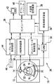
図1及び図2を参照すると、「第3世代」のCTスキャナに典型的なガントリ12を含むものとして、コンピュータ断層撮影(CT)イメージング・システム10を示している。ガントリ12は、このガントリ12の対向面上に位置する検出器アレイ18に向けてX線ビーム16を放出するX線源14を有する。検出器アレイ18は、投射され被検体22(例えば、患者)を透過したX線を一体となって検知する検出器素子20により形成される。検出器アレイ18は、単一スライス構成で製作される場合とマルチ・スライス構成で製作される場合がある。各検出器素子20は、入射したX線ビームの強度を表す電気信号、すなわち患者22を透過したX線ビームの減衰を表す電気信号を発生させる。X線投影データを収集するためのスキャンの間に、ガントリ12及びガントリ上に装着されたコンポーネントは回転中心24の周りを回転する。
【0011】
ガントリ12の回転及びX線源14の動作は、CTシステム10の制御機構26により制御される。制御機構26は、X線源14に電力及びタイミング信号を供給するX線制御装置28と、ガントリ12の回転速度及び位置を制御するガントリ・モータ制御装置30とを含む。制御機構26内にはデータ収集システム(DAS)32があり、これによって検出器素子20からのアナログ・データをサンプリングし、このデータを後続の処理のためにディジタル信号に変換する。画像再構成装置34は、サンプリングされディジタル化されたX線データをDAS32から受け取り、高速で画像再構成を行う。再構成された画像はコンピュータ36に入力として渡され、コンピュータにより大容量記憶装置38内に格納される。
【0012】
コンピュータ36はまた、キーボードを有するコンソール40を介して、オペレータからのコマンド及びスキャン・パラメータを受け取る。オペレータにより提供されるこうしたパラメータの1つは、データ収集用の公称スライス厚である。付属の陰極線管ディスプレイ42により、オペレータはコンピュータ36からの再構成画像やその他のデータを観察することができる。コンピュータ36は、オペレータの発したコマンド及びパラメータを用いて、DAS32、X線制御装置28及びガントリ・モータ制御装置30に対して制御信号や制御情報を提供する。さらにコンピュータ36は、モータ式テーブル46を制御してガントリ12内での患者22の位置決めをするためのテーブル・モータ制御装置44を操作する。詳細には、テーブル46により患者22の各部分はガントリ開口48を通過できる。
【0013】
図3を参照すると、典型的なマルチスライス型システムでは、X線ビーム16は線源14の焦点50から放出され、z軸においてビーム16のプロフィールを規定するための患者前置コリメータ52を通過するように投射される。コリメートされたビーム16は、複数の横列54(例えば、検出器素子20の4つの横列54)を含む検出器アレイ18に向けて投射される。隣接した横列56及び58は、それぞれ外側エッジ60及び62を有する検出器アレイ18の中央横列である。横列56の内側エッジ64は横列58の内側エッジ66に隣接している。
【0014】
実施の一形態では、イメージング・システム10のスライス厚を薄くするための方法は、一対の隣接した横列54(例えば、中央の横列56及び58)からイメージング・データ(例えば、投影データや投影データから作成した画像データ)を取得することを含む。さらに詳細には、ビーム16は、左側中央検出器横列56の外側エッジ60と右側中央検出器横列58の外側エッジ62を境界とする領域68の一部分を照射するように方向付けされる。例えば、ビーム16は、領域68の一部分内にビーム16が包含されるようにコリメータ52によりコリメートされる。
【0015】
上述のようにしてビーム16を中央の横列56及び58に方向付けしてイメージング・データを取得することによって、幾つかの臨床応用ではスライス厚が効果的に薄くされる。例えば、システム10の半値全幅(FWHM)間隔が1.25ミリメートルである場合、そのスライス厚は0.8〜0.9ミリメートルのFWHMまで減少(薄く)される。これ以上の厚さの減少はX線焦点50のサイズ、並びにシステム10の幾何学構成(すなわち、コリメータ52と焦点50の間の距離、及び検出器素子20と焦点50の間の距離)によって制限される。
【0016】
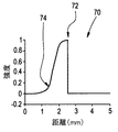
多くの臨床応用に対して、0.5ミリメートルのスライス厚を達成することが望ましい。したがって、別の実施形態では、領域68から取得したイメージング・データの少なくとも一部分を逆たたみ込みする。さらに詳細に述べると、図4では、図3に示すような照射を受けた際の横列56のような左側中央の横列に関する典型的なスライス感度プロフィール70を図示している。感度プロフィール70は、接合部(すなわち、横列56及び58のそれぞれの内側エッジ64及び66)によりビーム16の境界が規定される距離点である距離72において、ステップ関数に極めて近くなっている。コリメータ52により規定する場合、外側エッジ60に右側から近づくのに伴って、ビーム16の境界は徐々に低下して行く(例えば、距離74の周辺)。同様に図5を参照すると、横列58のような右側中央の横列に対する典型的なスライス感度プロフィール76は、内側エッジ64が内側エッジ66と落ち合う点である距離78において、ステップ関数に極めて近くなっている。コリメータ52により規定する場合、外側エッジ62に左側から近づくのに伴って、ビーム16の境界は徐々に低下して行く(例えば、距離80の周辺)。
【0017】
ステップ関数に近似したビーム16の境界とコリメータ規定したビーム16の境界との上述の相違により、マルチスライスのイメージング・データに対して単一スライス応用に関して周知の逆たたみ込みを適用した場合、アンダーシュートを効果的に補償することが困難となる。したがって実施の一形態では、逆たたみ込みをそのイメージング・データの一部分に対して適用する、例えば、逆たたみ込みを隣接した横列56及び58の各々に対して別々に適用する。さらに詳細に述べると、例えば、以下に記載した関係式を用いて、左側中央の横列56に対する逆たたみ込みは左外側エッジ60の方向に適用し、右側中央の横列58に対する逆たたみ込みは右外側エッジ62の方向に適用する。
【0018】
【数3】

上式において、P1A及びP1Bは、それぞれ左側中央検出器横列1A及び右側中央検出器横列1Bに対する元のイメージング・データ・サンプルであり、P’1A及びP’1Bは、それぞれ左側中央検出器横列1A及び右側中央検出器横列1Bに対する修正後のイメージング・データ・サンプルであり、WkA及びWkBは逆たたみ込みカーネル点である。
【0020】
例えば横列56と58に関して、元のスライス感度プロフィールは典型的には非対称であるため、例えば、式(1)及び式(2)において上述したように、逆たたみ込みに用いるすべてのデータ・サンプルが同じ横列54からのものであると、その逆たたみ込みの結果は向上する。したがって実施の一形態では、例えばアキシャル・スキャンに対するサンプリング・パターンは、図6に示すようにして実施される。イメージング・データ・サンプル90を取得した後、検出器アレイ18をz軸において一定の均等間隔だけ(例えば、横列54の公称スライス厚の半分だけ)増分させ、例えば横列56からの新たなサンプル92及び94が、例えば横列56から採取した以前のサンプルに少なくとも部分的に重なり合う(すなわち、またがる)ようにする。
【0021】
図7及び8はそれぞれ、スライス感度プロフィール70及び76に対する上述の方式による逆たたみ込みを図示したものである。図7及び8に示す実施形態では、逆たたみ込みを受けた感度プロフィール82及び84は、3点逆たたみ込みカーネルを用いて取得される。別の実施形態では、別のサイズをもつカーネルが使用される。
【0022】
上述のように片側逆たたみ込みを用いると、逆たたみ込みを受けたスライスの重心は元のスライス・プロフィールと比較してシフトする。(したがって、例えば、図6に示す横列58の第1のサンプル90の、横列56の第3のサンプル94上への明らかな重なりは、逆たたみ込みを通じて変更される。)図7及び8に示すように、実施の一形態による逆たたみ込みにより、横列56の重心86は右方向にシフトし、一方横列58の重心88は左方向にシフトする。
【0023】
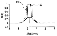
したがって実施の一形態として図7及び8を参照すると、横列56に対する逆たたみ込み済みのイメージング・データは、逆たたみ込みの前と後における横列56の重心86の位置の差96だけ右方向にシフトしている。同様に、横列58に対する逆たたみ込み済みのデータは、逆たたみ込みの前と後における横列58の重心88の位置の差98だけ左方向にシフトしている。逆たたみ込みを受けシフトを受けた横列56及び58からのイメージング・データを合成して、図9に示すようなスライス感度プロフィール100が得られる。図9には、逆たたみ込みする前の横列56及び58から合成したスライス・プロフィール102も示してある。
【0024】
したがって、上述の方法により、マルチスライス型システムのユーザは、元のFWHMが1.25ミリメートルであるシステムにおいて、0.64ミリメートルまでの狭いFWHM間隔を達成できる。したがって、そのスライス厚が薄くされ、かつ画像分解能がハードウェアの変更なしに向上する。
【0025】
本発明の具体的な実施形態を詳細に記載し図示してきたが、これらは説明および例示のためのものに過ぎず、本発明を限定する意図ではないことを明瞭に理解されたい。さらに、本明細書に記載したCTシステムは、X線源と検出器の双方がガントリと共に回転する「第3世代」システムである。検出器素子が個々に補正され所与のX線ビームに対して実質的に均一のレスポンスを提供できるならば、検出器が全周の静止した検出器でありかつX線源のみがガントリと共に回転する「第4世代」システムを含め、別の多くのCTシステムも使用可能である。さらに、本発明は、CTイメージング・システム以外の他のイメージング・システムにおいて実現することもできる。実施形態の幾つかでは、本明細書に記載した方法は、コンピュータ36と画像再構成装置34のいずれか一方又は両者を制御するソフトウェアまたはファームウェア、あるいはこれらの組み合わせによって実施される。さらに、本発明はコンピュータ36や画像再構成装置34以外の他のプロセッサを用いて実現することもできる。
【0026】
本発明を具体的な様々な実施形態に関して説明してきたが、本発明は、当業者であれば、特許請求の範囲の精神及び範疇の域内で修正を行って実施することができよう。
【図面の簡単な説明】
【図1】CTイメージング・システムの外観図である。
【図2】図1に示すシステムの概要ブロック図である。
【図3】典型的なマルチスライス型検出器アレイを照射しているX線ビームの幾何学構成を表した略図である。
【図4】図3に示すような照射を受けた際の、左側中央検出器素子横列に対する典型的なスライス感度プロフィールを表したグラフである。
【図5】図3に示すような照射を受けた際の、右側中央検出器素子横列に対する典型的なスライス感度プロフィールを表したグラフである。
【図6】実施の一形態によるマルチスライスのサンプリング・パターンの略図である。
【図7】実施の一形態による逆たたみ込みを受けた図4の左側中央検出器のスライス感度プロフィールを表したグラフである。
【図8】実施の一形態による逆たたみ込みを受けた図5の右側中央検出器のスライス感度プロフィールを表したグラフである。
【図9】実施の一形態により取得した合成スライス感度プロフィールのグラフである。
【符号の説明】
10 CTイメージング・システム
12 ガントリ
14 X線源
16 X線ビーム
18 検出器アレイ
20 検出器素子
22 患者、被検体
24 回転中心、アイソセンタ
26 制御機構
28 X線制御装置
30 ガントリ・モータ制御装置
32 データ収集システム(DAS)
34 画像再構成装置
36 コンピュータ
38 大容量記憶装置
40 コンソール
42 陰極線管ディスプレイ
44 テーブル・モータ制御装置
46 モータ式テーブル
48 ガントリ開口
50 X線焦点
52 患者前置コリメータ
54 検出器の横列
56 右側中央検出器横列
56 左側中央検出器横列
60 横列56の外側エッジ
62 横列58の外側エッジ
64 横列56の内側エッジ
66 横列58の内側エッジ
70、76 スライス感度プロフィール
82、84 逆たたみ込みを受けた感度プロフィール
86 横列56の重心
88 横列58の重心
90、92、94 イメージング・データ・サンプル
96 逆たたみ込みの前と後における横列56の重心位置の差
98 逆たたみ込みの前と後における横列58の重心位置の差
100 合成したスライス感度プロフィール
102 逆たたみ込みする前の横列56及び58から合成したスライス・プロフィール[0001]
BACKGROUND OF THE INVENTION
The present invention relates generally to tomographic imaging, and more particularly to a method and apparatus for generating computed tomography imaging data using a multi-slice imaging system.
[0002]
BACKGROUND OF THE INVENTION
In at least one configuration of a known computed tomography (CT) imaging system, the x-ray source is collimated to lie in the XY plane (commonly referred to as the “imaging plane”) of the Cartesian coordinate system. A fan beam (fan-shaped beam) is emitted. The X-ray beam passes through an image creation target such as a patient. After the beam is attenuated by this object, it is incident on the array of radiation detectors. The intensity of the attenuated beam radiation received at the detector array depends on the attenuation of the x-ray beam by the object. Each detector element of the array separately generates an electrical signal corresponding to a measurement of beam attenuation at the respective detector location. Attenuation measurements from all detectors are collected separately and a transmission profile is created.
[0003]
In the known third generation CT system, the X-ray source and detector array gantry around the image creation object in the image creation plane such that the angle at which the X-ray beam cuts through the image creation object varies constantly. Rotate with. A group of X-ray attenuation measurement values (ie, projection data) obtained from the detector array at a certain gantry angle is referred to as “view”. In addition, “scan data” to be imaged consists of a set of views obtained at various gantry angles, that is, view angles, while the X-ray source and the detector rotate once. In the axial scan, this projection data is processed, and an image corresponding to a two-dimensional slice obtained by transmitting the image creation target is formed. One method for reconstructing an image from a set of projection data is referred to in the art as the filtered backprojection method. In this processing method, the attenuation measurement value obtained by scanning is converted into an integer called “CT value”, also known as “Hounsfield value”, and the brightness of the corresponding pixel on the cathode ray tube display is converted using these integer values. Control.
[0004]
In known CT systems, the x-ray beam is projected from an x-ray source to pass through a pre-patient collimator for defining a profile of the x-ray beam in the patient's body axis (ie, the z-axis). The collimator typically includes an x-ray absorbing material for limiting an x-ray beam having an aperture therein.
[0005]
CT imaging systems typically provide image resolution within constraints imposed by factors such as collimator aperture size and slice thickness. In at least one CT system, its minimum slice thickness is 1.25 millimeters, and this value is mainly determined by the pitch size of the detector elements. In order to improve image resolution, it is desirable to reduce the slice thickness to less than 1 millimeter and to achieve the reduction in thickness with minimal impact on the imaging system hardware.
[0006]
To reduce slice thickness in a single slice imaging system, a portion of the detector element is illuminated and the imaging data (eg, projection data or image data) is deconvolutioned and reconstructed. It is known to reduce the full width at half maximum (FWHM) spacing of the slice profile. For multi-slice systems, it would be desirable to be able to achieve a similar slice width reduction without affecting the system hardware. However, when implementing this method for multi-slice imaging systems, problems arise because multi-slice sampling is limited, for example, by joints between adjacent detector rows. There is.
[0007]
It is desirable to use double slice imaging data collection and deconvolution techniques to reduce the slice thickness of a multi-slice imaging system without requiring system hardware changes.
[0008]
SUMMARY OF THE INVENTION
Accordingly, in one embodiment, the X-ray beam includes a source configured to be directed through the subject to a plurality of rows of detector elements, the plurality of rows of detector elements comprising projection data A method for reducing slice thickness is provided in a computed tomography imaging system that is configured to acquire a slice by slice. The method includes acquiring imaging data from a pair of adjacent rows, each having an outer edge, and deconvolves at least a portion of the imaging data acquired from a region bounded by the outer edge of the adjacent row. And synthesizing the deconvolved imaging data to obtain a slice sensitivity profile for the adjacent row pair.
[0009]
The method described above allows a user of a multi-slice imaging system to perform deconvolution of imaging data that reduces its slice thickness to less than 1 millimeter. Therefore, the image resolution is improved without requiring hardware change in the existing multi-slice imaging system.
[0010]
DETAILED DESCRIPTION OF THE INVENTION
Referring to FIGS. 1 and 2, a computed tomography (CT)
[0011]
The rotation of the
[0012]
[0013]
Referring to FIG. 3, in a typical multi-slice system, the
[0014]
In one embodiment, a method for reducing the slice thickness of the
[0015]
By directing the
[0016]
For many clinical applications, it is desirable to achieve a slice thickness of 0.5 millimeters. Thus, in another embodiment, at least a portion of the imaging data acquired from
[0017]
Due to the above differences between the
[0018]
[Equation 3]
Where P 1A and P 1B are the original imaging data samples for the left
[0020]
For example, for
[0021]
FIGS. 7 and 8 illustrate deconvolution in the manner described above for slice sensitivity profiles 70 and 76, respectively. In the embodiment shown in FIGS. 7 and 8, the deconvolved sensitivity profiles 82 and 84 are obtained using a three-point deconvolution kernel. In another embodiment, a kernel with a different size is used.
[0022]
When using one-sided deconvolution as described above, the center of gravity of the slice that has undergone deconvolution shifts compared to the original slice profile. (Thus, for example, the apparent overlap of the first sample 90 in the
[0023]
Thus, referring to FIGS. 7 and 8 as an embodiment, the deconvolved imaging data for the
[0024]
Thus, the method described above allows users of multi-slice systems to achieve narrow FWHM spacings up to 0.64 millimeters in systems where the original FWHM is 1.25 millimeters. Therefore, the slice thickness is reduced and the image resolution is improved without changing hardware.
[0025]
While specific embodiments of the present invention have been described and illustrated in detail, it should be clearly understood that these are for purposes of illustration and illustration only and are not intended to limit the invention. Furthermore, the CT system described herein is a “third generation” system where both the x-ray source and detector rotate with the gantry. If the detector elements are individually corrected to provide a substantially uniform response for a given x-ray beam, the detector is a full-round stationary detector and only the x-ray source rotates with the gantry Many other CT systems can also be used, including “fourth generation” systems. Furthermore, the present invention can be implemented in other imaging systems than CT imaging systems. In some embodiments, the methods described herein are implemented by software or firmware that controls one or both of
[0026]
While the invention has been described in terms of various specific embodiments, those skilled in the art will recognize that the invention can be practiced with modification within the spirit and scope of the claims.
[Brief description of the drawings]
FIG. 1 is an external view of a CT imaging system.
2 is a schematic block diagram of the system shown in FIG.
FIG. 3 is a schematic representation of the geometric configuration of an X-ray beam illuminating a typical multi-slice detector array.
FIG. 4 is a graph depicting a typical slice sensitivity profile for the left center detector element row when irradiated as shown in FIG. 3;
FIG. 5 is a graph depicting a typical slice sensitivity profile for the right center detector element row when irradiated as shown in FIG. 3;
FIG. 6 is a schematic diagram of a multi-slice sampling pattern according to one embodiment.
7 is a graph illustrating the slice sensitivity profile of the left center detector of FIG. 4 that has undergone deconvolution according to one embodiment.
8 is a graph depicting the slice sensitivity profile of the right center detector of FIG. 5 that has undergone deconvolution according to one embodiment.
FIG. 9 is a graph of a composite slice sensitivity profile obtained according to one embodiment.
[Explanation of symbols]
10
34
Claims (8)
さらに、前記線源(14)から放出されたX線ビーム(16)が前記隣接した横列対(56,58)の前記外側エッジ(60,62)を境界とする領域(68)の一部分を照射するように前記X線ビーム(16)を方向付けし、
コリメータ(52)をさらに備えると共に、前記領域(68)の前記一部分内に包含されるように前記ビーム(16)をコリメートするように構成されている請求項2に記載のシステム(10)。And further comprising a detector array (18), and the adjacent rows (56, 58) comprise a central row of the detector array;
Further, the X-ray beam (16) emitted from the radiation source (14) irradiates a part of the region (68) bounded by the outer edge (60, 62) of the adjacent row pair (56, 58). Directing the X-ray beam (16) to
The system (10) of claim 2, further comprising a collimator (52) and configured to collimate the beam (16) to be contained within the portion of the region (68).
さらに、少なくとも部分的に重なり合っているサンプル(90,92,94)をz軸に沿って均等間隔で取得するように構成されており、
前記均等間隔がイメージング・システムの公称横列スライス厚の半分である、請求項2に記載のシステム(10)。Configured to acquire imaging data from a pair of adjacent rows (56,58), configured to acquire imaging data samples (90,92,94) that are at least partially overlapping Including
And at least partially overlapping samples (90, 92, 94) are configured to be acquired at equal intervals along the z axis;
The system (10) of claim 2, wherein the even spacing is half the nominal row slice thickness of the imaging system.
Applications Claiming Priority (2)
| Application Number | Priority Date | Filing Date | Title |
|---|---|---|---|
| US09/566018 | 2000-05-08 | ||
| US09/566,018 US6366637B1 (en) | 2000-05-08 | 2000-05-08 | Methods and apparatus for generating thin-slice imaging data on a multi-slice imaging system |
Publications (3)
| Publication Number | Publication Date |
|---|---|
| JP2002034971A JP2002034971A (en) | 2002-02-05 |
| JP2002034971A5 JP2002034971A5 (en) | 2008-06-19 |
| JP4598302B2 true JP4598302B2 (en) | 2010-12-15 |
Family
ID=24261107
Family Applications (1)
| Application Number | Title | Priority Date | Filing Date |
|---|---|---|---|
| JP2001136771A Expired - Fee Related JP4598302B2 (en) | 2000-05-08 | 2001-05-08 | Method and apparatus for generating thin layer slice imaging data in a multi-slice imaging system |
Country Status (3)
| Country | Link |
|---|---|
| US (1) | US6366637B1 (en) |
| JP (1) | JP4598302B2 (en) |
| DE (1) | DE10122052A1 (en) |
Families Citing this family (6)
| Publication number | Priority date | Publication date | Assignee | Title |
|---|---|---|---|---|
| US6798860B1 (en) * | 2000-05-17 | 2004-09-28 | Ge Medical Systems Global Technology Company, Llc | Methods and apparatus for deconvolving imaging data |
| US6901131B2 (en) * | 2001-12-28 | 2005-05-31 | General Electric Company | Methods and apparatus for computed tomography imaging |
| US6963631B2 (en) * | 2002-10-25 | 2005-11-08 | Koninklijke Philips Electronics N.V. | Dynamic detector interlacing for computed tomography |
| SE525517C2 (en) * | 2003-03-06 | 2005-03-01 | Xcounter Ab | Device and method for scanning based detection of ionizing radiation |
| JP5800177B2 (en) * | 2010-02-26 | 2015-10-28 | 学校法人 愛知医科大学 | Tomographic image processing apparatus and tomographic image processing method |
| US9117304B2 (en) | 2013-07-31 | 2015-08-25 | General Electric Company | System and method for improved spatial resolution of a multi-slice imaging system |
Citations (1)
| Publication number | Priority date | Publication date | Assignee | Title |
|---|---|---|---|---|
| JP2000316841A (en) * | 1999-05-11 | 2000-11-21 | Hitachi Medical Corp | Multi-slice x-ray ct apparatus |
Family Cites Families (5)
| Publication number | Priority date | Publication date | Assignee | Title |
|---|---|---|---|---|
| JPS61154543A (en) * | 1984-12-27 | 1986-07-14 | 横河メディカルシステム株式会社 | Tomographic reconstitution apparatus of ct apparatus |
| US5262946A (en) * | 1988-10-20 | 1993-11-16 | Picker International, Inc. | Dynamic volume scanning for CT scanners |
| IL119033A0 (en) * | 1996-08-07 | 1996-11-14 | Elscint Ltd | Multi-slice detector array |
| US5864598A (en) * | 1997-04-21 | 1999-01-26 | General Electric Company | Methods and apparatus for scanning an object in a computed tomography system |
| US6061419A (en) * | 1998-08-25 | 2000-05-09 | General Electric Company | Methods and apparatus for noise compensation in an imaging system |
-
2000
- 2000-05-08 US US09/566,018 patent/US6366637B1/en not_active Expired - Fee Related
-
2001
- 2001-05-07 DE DE10122052A patent/DE10122052A1/en not_active Withdrawn
- 2001-05-08 JP JP2001136771A patent/JP4598302B2/en not_active Expired - Fee Related
Patent Citations (1)
| Publication number | Priority date | Publication date | Assignee | Title |
|---|---|---|---|---|
| JP2000316841A (en) * | 1999-05-11 | 2000-11-21 | Hitachi Medical Corp | Multi-slice x-ray ct apparatus |
Also Published As
| Publication number | Publication date |
|---|---|
| JP2002034971A (en) | 2002-02-05 |
| DE10122052A1 (en) | 2001-11-15 |
| US6366637B1 (en) | 2002-04-02 |
Similar Documents
| Publication | Publication Date | Title |
|---|---|---|
| EP1374776B1 (en) | Methods and apparatus for operating a radiation source | |
| US6421411B1 (en) | Methods and apparatus for helical image artifact reduction | |
| JP4516256B2 (en) | Local CT image reconstruction with limited X-ray exposure | |
| US5864598A (en) | Methods and apparatus for scanning an object in a computed tomography system | |
| US7113569B2 (en) | X-ray CT apparatus | |
| JP4663150B2 (en) | Method and apparatus for region of interest multi-slice CT scanning | |
| US6421412B1 (en) | Dual cardiac CT scanner | |
| JP4367884B2 (en) | Method and apparatus for leveling calcification | |
| US6990170B2 (en) | X-ray computed tomographic imaging apparatus | |
| EP1114617B1 (en) | Methods and apparatus for automatic patient positioning | |
| EP1387321A2 (en) | Methods and apparatus for weighting of computed tomography data | |
| EP0981998A1 (en) | Methods and apparatus for automatic image noise reduction | |
| JP2002345808A (en) | Method and system for process of scouting ct images | |
| JP4846937B2 (en) | High-pitch reconstruction of multi-slice CT scan | |
| EP1464286B1 (en) | Apparatus and method for x-ray computed tomography | |
| US6343110B1 (en) | Methods and apparatus for submillimeter CT slices with increased coverage | |
| US6269139B1 (en) | Methods and apparatus for pre-filtering weighting in image reconstruction | |
| JP4598302B2 (en) | Method and apparatus for generating thin layer slice imaging data in a multi-slice imaging system | |
| JP4832662B2 (en) | Method and apparatus for deconvolution of imaging data | |
| US6687327B2 (en) | System and method of medical imaging having task and/or patient size dependent processing | |
| JP2001286462A (en) | Method and device of adapted interpolation type reduced view ct scanning | |
| US6463117B1 (en) | Methods and apparatus for tilted helical image reconstruction in CT imaging | |
| JPS6233897B2 (en) |
Legal Events
| Date | Code | Title | Description |
|---|---|---|---|
| A521 | Request for written amendment filed |
Free format text: JAPANESE INTERMEDIATE CODE: A523 Effective date: 20080502 |
|
| A621 | Written request for application examination |
Free format text: JAPANESE INTERMEDIATE CODE: A621 Effective date: 20080502 |
|
| A131 | Notification of reasons for refusal |
Free format text: JAPANESE INTERMEDIATE CODE: A131 Effective date: 20100727 |
|
| A977 | Report on retrieval |
Free format text: JAPANESE INTERMEDIATE CODE: A971007 Effective date: 20100729 |
|
| A521 | Request for written amendment filed |
Free format text: JAPANESE INTERMEDIATE CODE: A523 Effective date: 20100806 |
|
| RD02 | Notification of acceptance of power of attorney |
Free format text: JAPANESE INTERMEDIATE CODE: A7422 Effective date: 20100806 |
|
| RD04 | Notification of resignation of power of attorney |
Free format text: JAPANESE INTERMEDIATE CODE: A7424 Effective date: 20100806 |
|
| TRDD | Decision of grant or rejection written | ||
| A01 | Written decision to grant a patent or to grant a registration (utility model) |
Free format text: JAPANESE INTERMEDIATE CODE: A01 Effective date: 20100831 |
|
| A01 | Written decision to grant a patent or to grant a registration (utility model) |
Free format text: JAPANESE INTERMEDIATE CODE: A01 |
|
| A61 | First payment of annual fees (during grant procedure) |
Free format text: JAPANESE INTERMEDIATE CODE: A61 Effective date: 20100924 |
|
| R150 | Certificate of patent or registration of utility model |
Free format text: JAPANESE INTERMEDIATE CODE: R150 |
|
| FPAY | Renewal fee payment (event date is renewal date of database) |
Free format text: PAYMENT UNTIL: 20131001 Year of fee payment: 3 |
|
| LAPS | Cancellation because of no payment of annual fees |