JP4597353B2 - Method and apparatus for providing uniform ignition within an augmentor - Google Patents
Method and apparatus for providing uniform ignition within an augmentor Download PDFInfo
- Publication number
- JP4597353B2 JP4597353B2 JP2000386191A JP2000386191A JP4597353B2 JP 4597353 B2 JP4597353 B2 JP 4597353B2 JP 2000386191 A JP2000386191 A JP 2000386191A JP 2000386191 A JP2000386191 A JP 2000386191A JP 4597353 B2 JP4597353 B2 JP 4597353B2
- Authority
- JP
- Japan
- Prior art keywords
- igniter
- augmentor
- housing
- lead
- body portion
- Prior art date
- Legal status (The legal status is an assumption and is not a legal conclusion. Google has not performed a legal analysis and makes no representation as to the accuracy of the status listed.)
- Expired - Fee Related
Links
Images


Classifications
-
- F—MECHANICAL ENGINEERING; LIGHTING; HEATING; WEAPONS; BLASTING
- F02—COMBUSTION ENGINES; HOT-GAS OR COMBUSTION-PRODUCT ENGINE PLANTS
- F02K—JET-PROPULSION PLANTS
- F02K3/00—Plants including a gas turbine driving a compressor or a ducted fan
- F02K3/08—Plants including a gas turbine driving a compressor or a ducted fan with supplementary heating of the working fluid; Control thereof
- F02K3/10—Plants including a gas turbine driving a compressor or a ducted fan with supplementary heating of the working fluid; Control thereof by after-burners
-
- F—MECHANICAL ENGINEERING; LIGHTING; HEATING; WEAPONS; BLASTING
- F02—COMBUSTION ENGINES; HOT-GAS OR COMBUSTION-PRODUCT ENGINE PLANTS
- F02C—GAS-TURBINE PLANTS; AIR INTAKES FOR JET-PROPULSION PLANTS; CONTROLLING FUEL SUPPLY IN AIR-BREATHING JET-PROPULSION PLANTS
- F02C7/00—Features, components parts, details or accessories, not provided for in, or of interest apart form groups F02C1/00 - F02C6/00; Air intakes for jet-propulsion plants
- F02C7/26—Starting; Ignition
- F02C7/264—Ignition
- F02C7/266—Electric
-
- F—MECHANICAL ENGINEERING; LIGHTING; HEATING; WEAPONS; BLASTING
- F05—INDEXING SCHEMES RELATING TO ENGINES OR PUMPS IN VARIOUS SUBCLASSES OF CLASSES F01-F04
- F05D—INDEXING SCHEME FOR ASPECTS RELATING TO NON-POSITIVE-DISPLACEMENT MACHINES OR ENGINES, GAS-TURBINES OR JET-PROPULSION PLANTS
- F05D2240/00—Components
- F05D2240/90—Mounting on supporting structures or systems
Description
【0001】
【発明の属する技術分野】
本発明は、オーグメンタに関し、より具体的には、オーグメンタの点火器に関する。
【0002】
【従来の技術】
オーグメンタは、飛行性能限界に必要な推力を増強するためにガスタービンエンジンに用いられる。点火器は、一般的にはオーグメンタの底部近傍の円周方向に設置される。点火器は、点火器取付アセンブリと、点火器ボックスから点火器先端まで延びる点火器リードとを一般に含む。点火器先端は、オーグメンタに対して点火供給装置を準備する。
【0003】
点火器取付アセンブリは、点火器をオーグメンタに固定する。一般的に、取付アセンブリは、複数の締め具でオーグメンタに固定された点火器ハウジングを含む。点火器ハウジングは、点火器がそれを通してオーグメンタまで延びることができる両端の開口部を含む。点火器は、点火器先端が所定の挿入深度までオーグメンタ内に延びるように装置される。
【0004】
ガスタービンエンジンの運転中は、燃料及び空気が、高い温度及び速度でオーグメンタを通って流れる。高温の燃料及び空気により、オーグメンタとその関連構成要素とは、熱応力と熱膨張とに曝される。そのような熱膨張は、しばしば点火器を半径方向内方の点火領域に押しやることになり、点火器先端温度を上昇させ、その点火器先端の寿命を低下させる。結果として、点火器先端は、絶えず不整合になり、関連するガスタービンエンジンの全体的な性能を低下させ得る。一般に浮動フェルール装置が点火器先端と点火領域との間のインタフェースに含まれており、そのような点火器先端の不整合が修正される。
【0005】
【発明が解決しようとする課題】
熱膨張が点火器に悪影響を及ぼすのを防止しようとして、嵩張った調整可能な点火器取付アセンブリが用いられている。そのようなアセンブリは、互いにしっかりと固定された複数の構成要素を含み、どの1つの構成要素も他の構成要素と無関係には熱膨張できないようになっている。従って、構成要素は、熱膨張の結果不整合や不適切な挿入深度を引き起こす。その上に、嵩張った浮動フェルールアセンブリは、オーグメンタ点火領域から外方に延びて、他のガスタービンエンジン構成要素を冷却するために用いられる冷却空気を阻止する。更にまた、構成要素が互いに固定されるために、点火器先端は、取付アセンブリに関しては適正に整合されたままではあるが、オーグメンタに関しては適正な挿入深度又は整合のまま保持されない可能性がある。結果として、全体的なガスタービンの点火性能は低下する。
【0006】
【課題を解決するための手段】
例示的な実施形態において、オーグメンタは、点火器先端を適切な挿入深度に維持する点火器取付アセンブリを含む。点火器は、点火器リードと点火器ハウジングアセンブリとを含む。点火器リードは、点火器ボックスから延びて点火器先端で終端する。ハウジングアセンブリは、1対の締め具でオーグメンタに固定され、点火器は、戻り止めナットでハウジングアセンブリの内部に固定される。
【0007】
点火器及び点火器ハウジングはまた、点火器と点火器ハウジングとの間に連結されるバイアス機構も含む。そのバイアス機構は、点火器をオーグメンタに対してバイアスし、点火器先端が、ガスタービンエンジンの運転中にオーグメンタ点火領域の内部で適切な挿入深度に確実に維持されるようにする。その上に、点火器は、オーグメンタ内部に配置された面取りした開口部に収容される寸法に作られた整合支持ボスを含む。その整合支持ボスと面取りした開口部とを組み合わせれば、点火器がオーグメンタに完全に取り付けられた時、自動的に点火器先端が整合され、正しく作動することになる。更にその上に、ガスタービンエンジンが運転されると、バイアス機構で点火器先端がオーグメンタ内部で適切な挿入深度に維持される。更に、点火器が点火器ハウジングの内部に戻り止めナットだけで固定されるので、点火器を保守する労力は合理化される。
【0008】
【発明の実施の形態】
図1は、低圧の圧縮機12と、高圧の圧縮機14と、燃焼器16とを含むガスタービンエンジン10の概略図である。エンジン10はまた、高圧タービン18と、低圧タービン20と、オーグメンタ24を含む。
【0009】
作動している時、空気は、低圧圧縮機12を通って流れ、圧縮空気は、低圧圧縮機12から高圧圧縮機14に供給される。高度に圧縮された空気は、次に燃焼器16に送られ、燃焼器16からの空気流がタービン18及び20を駆動する。
空気流は、タービン20とバイパスダクト26とからオーグメンタ24に入る。
オーグメンタ24は、少なくとも1つの点火器(図1には図示しない)でその空気流に再点火し、空気流は、ノズル28を通ってガスタービンエンジン10を出る。
【0010】
図2は、ガスタービンエンジン10のようなガスタービンエンジンに用いられる点火器30の完成図である。点火器30は、第1の本体部分32と第2の本体部分34とを持つ点火器リード31を含む。第1の本体部分32は、第2の本体部分34からコネクタ36まで延びる。コネクタ36は、点火器リード31の直径40よりも大きい直径38を持つ。コネクタ直径38により、コネクタ36が点火ボックス(図示しない)から延びる可撓性リード(図示しない)に装着されることができる。第2の本体部分34は、点火器の第1の本体部分32から点火器先端42まで延びる。
【0011】
点火器第1本体部分32は、そこから点火器第2本体部分34まで延びる屈曲部44を含む。屈曲部44は、点火器第1本体部分32が点火器第2本体部分34と実質的に垂直になるように湾曲している。
【0012】
ナット保持カラー50は、点火器リード31から点火器屈曲部44と点火器第2本体部分34との間に延びる。ナット保持カラー50は、点火器リードの直径40より大きい直径52を持つ。直径52はまた、戻り止めナット54の開口部(図2には図示しない)の内径(図2には図示しない)より大きい。戻り止めナット54は、点火器30周りに円周方向に配置されて、キャップ(図2には図示しない)と複数のねじすじ(図示しない)とを含む。そのねじすじは、点火器ハウジング(図2には図示しない)と係合するような寸法に作られて、戻り止めナット54を点火器ハウジングに固定するが、一方、点火器30は、点火器ハウジングと摺動可能に接触したままである。従って、点火器30は、ナット保持カラー50が戻り止めナット54と接触し得るように、点火器ハウジングに対して摺動可能である。キャップの開口部の直径は、ナット保持カラー50の直径52より小さい。従って、ナット保持カラー50は、点火器第2本体部分34が戻り止めナット54を通って移動する量を制限する。
【0013】
戻り止めナットキャップは、戻り止めナット54が点火器ハウジングに締め付けられると、点火器圧縮ばね60を圧縮するように構成される。圧縮ばね60は、戻り止めナット54とOリング溝62との間で点火器リード31周りの円周方向に置かれるバイアス機構である。圧縮ばね60の第1端部(図2には図示しない)は、戻り止めナットのキャップに隣接する戻り止めナット54の内部に置かれ、また、圧縮ばね60の第2端部61は、Oリング溝62に隣接して置かれる。Oリング溝62は、点火器ハウジングと密封的に接触するOリング(図2には図示しない)を収容する寸法に作られる。
【0014】
点火器第2本体部分34は、浮動フェルール(図2には図示しない)と密封的に接触する第2のOリング(図2には図示しない)を収容する寸法に作られた第2のOリング溝66を含む。第2Oリング溝66は、Oリング溝62と点火器先端42との間に置かれる。整合支持ボス70は、点火器リード31からOリング溝66と点火器先端42との間の半径方向外方に延びる。整合支持ボス70は、球形でオーグメンタ保炎器(図2には図示しない)の内部に配置された開口部(図2には図示しない)に収容される寸法に作られた球面断面の輪郭(図2には図示しない)を持つ。
【0015】
図3は、点火器取付アセンブリ76を備えるオーグメンタ24に装着された点火器30の完成図である。点火器取付アセンブリ76は、外面83を持つ点火器ハウジング82を含む。外面83は、点火器戻り止めナットのねじすじを受け入れる寸法に作られた複数のねじすじ(図示しない)を備える。点火器30がオーグメンタ24に完全に装着された時、点火器ハウジング82は、点火器リード31周りの円周方向に配置される。点火器ハウジング82は、第1本体部分84と第2本体部分86とを含む。第1本体部分84は、円筒形で第2本体部分86から点火器ハウジング82の第1端部(図3には図示しない)まで延びる。点火器ハウジングのねじすじは、点火器ハウジング第1端部に近接して置かれる。
【0016】
点火器ハウジングの第2本体部分86は、実質的に平坦な部材で1対の開口部88及び90を含む。点火器ハウジングの第2本体部分86は、ハウジングパッド92の内部に収容される寸法に作られる。ハウジングパッド92は、オーグメンタダクト94の内部に置かれ、点火器ハウジングの第2本体部分86が機械加工された表面(図示しない)にきちんと嵌め込まれるように機械加工される。1つの実施形態において、ハウジングパッド92は、平行四辺形の形状を持つ。開口部88及び90は円筒形で、それを通ってオーグメンタダクト94内部に配置された1対のねじ切りされた開口部(図示しない)内に延びる1対の締め具(図示しない)を収容する寸法に作られる。1つの実施形態において、その締め具は、直径0.19インチのボルトである。
【0017】
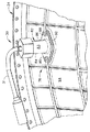
図4は、オーグメンタ24に装着された点火器30の断面図である。オーグメンタ24は、オーグメンタダクト94と、オーグメンタライナ100と、保炎器102とを含む。オーグメンタダクト94は、オーグメンタライナ100周りの円周方向に配置され、点火器ハウジング82がしっかり固定される外面104を準備する。オーグメンタライナ100は、保炎器102周りの円周方向に配置され、冷却空気用環状体106を保炎器102から分離する。冷却空気用環状体106は、オーグメンタダクト94とオーグメンタライナ100との間に置かれて通路を設け、それを通って冷却空気が流れ、ガスタービンエンジン10の排気ダクト(図示しない)とオーグメンタライナ100とを冷却する。保炎器102は、高温の燃焼ガスと空気流とをオーグメンタ24を通ってガスタービンエンジン排気ダクトに送る。
【0018】
点火器リード31は、第1Oリング110と第2Oリング112とを含む。第1Oリング110は、Oリング溝62内に嵌まるような寸法に作られ、第2Oリング112は、Oリング溝66内に嵌まるような寸法に作られる。Oリング溝62は、Oリング溝66の直径(図示しない)より僅かに大きい直径(図示しない)を持つ。溝62及び66の各々は、点火器リード31から半径方向外方に延びる環状突出部116及び118の内側に形成される。環状突出部116は、直径120を持ち、また環状突出部118は、直径122を持つ。直径120は、点火器ハウジング82の内径124より僅かに小さいので、点火器リード31がオーグメンタ24の内部に完全に装置された時、第1Oリング110を点火器ハウジング82と密封可能に接触させる。Oリング110は、冷却空気が点火器ハウジング82を通って漏出するのを防止する。
【0019】
点火器第2本体部分34は初め、緩く装着された点火器ハウジング第1本体部分84の第1端部130を通り、それから点火器ハウジング第2本体部分86を通って挿入される。点火器ハウジングの第2本体部分86は、ハウジングパッド92内に挿入され、それから点火器ハウジング82は、締め具でオーグメンタダクト94に固定される。
【0020】
点火器リード31は、次にオーグメンタダクト94内に配置された開口部132を通って挿入される。開口部132は、点火器ハウジング82の内径124に実質的に等しい直径134を持つ。ハウジングパッド92は、開口部132周りの円周方向に置かれる。
【0021】
点火器リード31は、冷却空気用環状体106を通ってオーグメンタライナ100の内に配置された開口部140の中に更に挿入される。浮動フェルール142は、開口部140から冷却空気用環状体106の中に延びる。浮動フェルール142は、ほぼ円筒形で、点火器ハウジング82がオーグメンタダクト94に装着された後は、実質的に点火器ハウジング82及び点火器第2本体部分34と同軸である。開口部140と浮動フェルール142とは、環状突出部118の直径122より僅かに大きい直径144を持つ。従って、Oリング112が溝66内に装着され、点火器30がオーグメンタ24に装着された時、Oリング112は、浮動フェルール142と密封可能に接触する。Oリング112と浮動フェルール142との間に密封可能な接触があれば、燃料がオーグメンタライナ100を通って冷却空気用環状体106内に漏出するのが防止される。
【0022】
点火器リード31は、次に保炎器102内に配置された開口部150を通って挿入され、そして保炎器102から半径方向外方に延びる。開口部150は、円筒形で上縁部152と下縁部154とを持つ。下縁部154は、保炎器102から上縁部152まで延びる。上縁部152は、円錐形で点火器整合支持ボス70を収容する。整合支持ボス70は、球面断面の輪郭156を持ち、第1の直径160と第2の直径162とを持つ。第1直径160は、点火器リード31から延び、点火器リード直径40と実質的に等しい。第2直径162は、第1直径160より大きく、点火器リード31から第1直径160とオーグメンタライナ100との間に延びる。整合支持ボスの球形輪郭156と面取りした開口部150との組み合わせにより、点火器リード31は、オーグメンタ24内に完全に挿入されることができるが、同時に点火器先端42は、ガスタービンエンジンの運転に適する整合状態に自己調節される。
【0023】
点火器戻り止めナット54は、開口部168を持つキャップ166を含む。開口部168は、点火器直径40よりは大きくナット保持カラー50の直径52よりは小さい直径170を持つ。キャップ開口部直径170により、Oリング110と点火器ハウジング82との間の密封を維持しながら、点火器リード31をオーグメンタ24と点火器ハウジング82とに関して枢転可能にする。
【0024】
戻り止めナット54が締め付けられると、戻り止めナットキャップ166は、圧縮機ばね60の第1端部172と接触する一方、圧縮ばね第2端部61は、環状突出部116と接触する。戻り止めナット54を締め付けると、圧縮ばね60が圧縮され、点火器30がオーグメンタ24に対してバイアスされ、点火器先端42が保炎器102内で適切な挿入深度で維持される。更に、戻り止めナットが締め付けられると、Oリング110は、点火器ハウジング82との密封可能な接触を維持し、また、Oリング112は、浮動フェルール142との密封可能な接触を維持する。あるいは、圧縮ばね60は、点火器ハウジング82の内径124とほぼ等しい直径を持つ第1端部172が第2端部61より小さいか又は大きくなるように、テーパ付けすることができる。
【0025】
ガスタービンエンジン10の運転中に、オーグメンタ24は、高い温度と圧力とに曝され、熱膨張と許容限界とを引き起こす。熱膨張の結果として、点火器先端42は、保炎器102からオーグメンタダクト94に向かって外方に押しやられる。圧縮ばね60は、ガスタービンエンジンの運転中、点火器30を保炎器に対してバイアスし、点火器先端42をオーグメンタ24内で適切な挿入深度に維持する。更に、圧縮ばね60は、整合支持ボス70にバイアスをかけ、その保炎器開口部150との接触を保ち、ガス流路の密封を保つようにする。球形かつ円錐形の整合支持ボス70と面取りした保炎器開口部150との組み合わせで、エンジン運転中、点火器先端42がオーグメンタ24内で適切な整合状態を維持し、点火器リード31の半径方向、軸線方向、及び、接線方向の動きが可能になる。1つの実施形態において、半径方向の移動能力は、0.45インチにほぼ等しい。
【0026】
上記の点火器は、経済性に優れ、高い信頼性がある。点火器は、点火器ハウジングとバイアス機構とを含む。点火器は、戻り止めナットで点火器ハウジングに固定され、戻り止めナットが締め付けられた後、点火器ハウジングと摺動可能な接触を続ける。バイアス機構は、点火器が熱歪みや熱膨張を被った場合、点火器先端の適切な挿入深度を維持しながら、点火器の半径方向の移動を可能にする。その結果、オーグメンタを一様な点火で作動させる点火器がもたらされる。すなわち、対応するガスタービンエンジンは、高い効率及び性能で運転することができる。
【0027】
本発明は、様々な特定の実施形態に関して説明されてきたが、当業者は、本発明の精神及び範囲から逸脱することなく、その変形によっても本発明が実施され得ることを理解するであろう。
【図面の簡単な説明】
【図1】 ガスタービンエンジンの概略図。
【図2】 図1に示すガスタービンエンジンに使用され得る点火器の完成図。
【図3】 オーグメンタに装着された図2に示す点火器の完成図。
【図4】 オーグメンタに装着された図3に示す点火器の断面図。
【符号の説明】
10 ガスタービンエンジン
12 低圧圧縮機
14 高圧圧縮機
16 燃焼器
18 高圧タービン
20 低圧タービン
24 オーグメンタ
26 バイパスダクト
28 ノズル
30 点火器
31 点火器リード
32 点火器第1本体部分
34 点火器第2本体部分
36 コネクタ
38 コネクタ直径
40 点火器リード直径
42 点火器先端
44 点火器本体の屈曲部
50 ナット保持カラー
52 ナット保持カラーの直径
54 戻り止めナット
60 点火器圧縮ばね
61 圧縮ばね第2端部
62 Oリング溝
66 第2Oリング溝
70 整合支持ボス
76 点火器取付アセンブリ
82 点火器ハウジング
83 点火器ハウジング外面
84 点火器ハウジングの第1本体部分
86 点火器ハウジングの第2本体部分
88 点火器本体部分の開口部
90 点火器本体部分の開口部
92 ハウジングパッド
94 オーグメンタダクト
100 オーグメンタライナ
102 保炎器
104 オーグメンタダクト外面
106 冷却空気用環状体
110 第1Oリング
112 第2Oリング
116 第1環状突出部
118 第2環状突出部
120 第1突出部の直径
122 第2突出部の直径
124 点火器ハウジングの内径
130 点火器ハウジングの第1端部
132 オーグメンタダクト開口部
134 オーグメンタダクト開口部の直径
140 オーグメンタライニング開口部
142 浮動フェルール
144 浮動フェルールの直径
150 保炎器開口部
152 保炎器開口部の上縁部
154 保炎器開口部の下縁部
156 整合支持ボスの球形断面輪郭
160 整合支持ボスの第1直径
162 整合支持ボスの第2直径
166 点火器戻り止めナットキャップ
168 ナットキャップ開口部
170 ナットキャップ開口部の直径
172 圧縮ばねの第1端部[0001]
BACKGROUND OF THE INVENTION
The present invention relates to an augmentor, and more specifically to an igniter for an augmenter.
[0002]
[Prior art]
Augmentors are used in gas turbine engines to increase the thrust required for flight performance limits. The igniter is generally installed in a circumferential direction near the bottom of the augmenter. The igniter generally includes an igniter mounting assembly and an igniter lead that extends from the igniter box to the igniter tip. The tip of the igniter prepares an ignition supply device for the augmenter.
[0003]
The igniter mounting assembly secures the igniter to the augmentor. Generally, the mounting assembly includes an igniter housing that is secured to the augmenter with a plurality of fasteners. The igniter housing includes openings at both ends through which the igniter can extend to the augmentor. The igniter is configured such that the igniter tip extends into the augmenter to a predetermined insertion depth.
[0004]
During operation of the gas turbine engine, fuel and air flow through the augmentor at high temperatures and speeds. With the hot fuel and air, the augmentor and its associated components are exposed to thermal stress and thermal expansion. Such thermal expansion often pushes the igniter into the radially inward ignition region, increasing the igniter tip temperature and reducing the life of the igniter tip. As a result, the igniter tip can be constantly misaligned and can degrade the overall performance of the associated gas turbine engine. Generally, a floating ferrule device is included at the interface between the igniter tip and the ignition region, and such igniter tip misalignment is corrected.
[0005]
[Problems to be solved by the invention]
In an attempt to prevent thermal expansion from adversely affecting the igniter, a bulky adjustable igniter mounting assembly is used. Such an assembly includes a plurality of components that are firmly secured to one another such that no one component can thermally expand independently of the other components. Thus, the components cause mismatch and improper insertion depth as a result of thermal expansion. In addition, the bulky floating ferrule assembly extends outward from the augmentor ignition region and blocks cooling air used to cool other gas turbine engine components. Furthermore, because the components are secured together, the igniter tip may remain properly aligned with respect to the mounting assembly, but may not be held at the proper insertion depth or alignment with respect to the augmentor. As a result, the overall gas turbine ignition performance is reduced.
[0006]
[Means for Solving the Problems]
In an exemplary embodiment, the augmentor includes an igniter mounting assembly that maintains the igniter tip at the proper insertion depth. The igniter includes an igniter lead and an igniter housing assembly. The igniter lead extends from the igniter box and terminates at the igniter tip. The housing assembly is secured to the augmentor with a pair of fasteners, and the igniter is secured within the housing assembly with a detent nut.
[0007]
The igniter and igniter housing also include a biasing mechanism that is coupled between the igniter and the igniter housing. The biasing mechanism biases the igniter relative to the augmentor to ensure that the igniter tip is maintained at the proper insertion depth within the augmentor ignition region during operation of the gas turbine engine. In addition, the igniter includes an alignment support boss dimensioned to be received in a chamfered opening disposed within the augmenter. Combining the alignment support boss with the chamfered opening automatically aligns the igniter tip and operates correctly when the igniter is fully attached to the augmentor. Furthermore, when the gas turbine engine is operated, a bias mechanism maintains the igniter tip at the proper insertion depth inside the augmentor. Furthermore, the effort to maintain the igniter is streamlined because the igniter is secured only within the igniter housing with a detent nut.
[0008]
DETAILED DESCRIPTION OF THE INVENTION
FIG. 1 is a schematic diagram of a
[0009]
When operating, air flows through the
Airflow enters the augmenter 24 from the
Augmentor 24 reignites the air flow with at least one igniter (not shown in FIG. 1) that exits
[0010]
FIG. 2 is a completed view of an
[0011]
The igniter
[0012]
A
[0013]
The detent nut cap is configured to compress the
[0014]
The igniter
[0015]
FIG. 3 is a completed view of the
[0016]
The
[0017]
FIG. 4 is a cross-sectional view of the
[0018]
The
[0019]
The igniter
[0020]
The
[0021]
The
[0022]
The
[0023]
The
[0024]
When the
[0025]
During operation of the
[0026]
The above igniter is excellent in economic efficiency and highly reliable. The igniter includes an igniter housing and a biasing mechanism. The igniter is secured to the igniter housing with a detent nut and, after the detent nut is tightened, continues slidable contact with the igniter housing. The biasing mechanism allows radial movement of the igniter while maintaining the proper insertion depth of the igniter tip when the igniter is subjected to thermal distortion or thermal expansion. The result is an igniter that operates the augmenter with uniform ignition. That is, the corresponding gas turbine engine can be operated with high efficiency and performance.
[0027]
Although the invention has been described in terms of various specific embodiments, those skilled in the art will recognize that the invention can be practiced with modifications without departing from the spirit and scope of the invention. .
[Brief description of the drawings]
FIG. 1 is a schematic view of a gas turbine engine.
FIG. 2 is a completed view of an igniter that can be used in the gas turbine engine shown in FIG. 1;
FIG. 3 is a completed view of the igniter shown in FIG. 2 attached to an augmenter.
4 is a cross-sectional view of the igniter shown in FIG. 3 mounted on an augmenter.
[Explanation of symbols]
10 gas turbine engine 12 low pressure compressor 14 high pressure compressor 16 combustor 18 high pressure turbine 20 low pressure turbine 24 augmentor 26 bypass duct 28 nozzle 30 igniter 31 igniter lead 32 igniter first body portion 34 igniter second body portion 36 Connector 38 connector diameter 40 igniter lead diameter 42 igniter tip 44 igniter body bent portion 50 nut retaining collar 52 nut retaining collar diameter 54 detent nut 60 igniter compression spring 61 compression spring second end 62 O-ring groove 66 second O-ring groove 70 alignment support boss 76 igniter mounting assembly 82 igniter housing 83 igniter housing outer surface 84 igniter housing first body portion 86 igniter housing second body portion 88 igniter body portion opening 90 Opening 92 of igniter body portion housing Pad 94 Augmentor duct 100 Augmentor liner 102 Flame holder 104 Augmentor duct outer surface 106 Cooling air ring 110 First O ring 112 Second O ring 116 First annular protrusion 118 Second annular protrusion 120 Second annular protrusion 120 Diameter 122 Diameter of second protrusion 124 Inner diameter 130 of igniter housing First end 132 of igniter housing Augmentor duct opening 134 Augmentor duct opening diameter 140 Augmentor lining opening 142 Floating ferrule 144 Floating ferrule Diameter 150 Flame holder opening 152 Upper edge 154 of flame holder opening Lower edge 156 of flame holder opening Spherical cross-sectional profile 160 of alignment support boss First diameter 162 of alignment support boss Second alignment support boss Diameter 166 igniter detent nut cap 168 nut cap The first end having a diameter of 172 compression spring flop opening 170 cap nut opening
Claims (10)
第2本体部分からコネクタ(36)まで延びる第1本体部分(32)、第1本体部分から点火器先端まで延びる第2本体部分(34)、点火器先端(42)、及び、コネクタ(36)を含む点火器リード(31)と、
ガスタービンエンジンの運転中、前記オーグメンタ点火器(30)が前記ガスタービンに接続されたとき、前記点火器先端を一定の挿入深度に維持するため、前記点火器リードに連結され、前記点火器リードを前記保炎器に対してバイアスするよう配置されたバイアス機構(60)と、
を含み、
前記オーグメンタ点火器は、前記点火器リード第2本体部分(34)周りの円周方向に配置され、前記点火器が前記オーグメンタライナに対して移動できるように構成された浮動フェルール(142)を更に含むことを特徴とするオーグメンタ点火器。An augmentor igniter (30) for a gas turbine engine (10) comprising a flame holder (102) , an augmenter liner (100) and an augmentor duct (94), comprising:
A first body portion (32) extending from the second body portion to the connector (36), a second body portion (34) extending from the first body portion to the igniter tip, an igniter tip (42), and a connector (36) An igniter lead (31) comprising:
During operation of the gas turbine engine, when the augmentor igniter (30) is connected to the gas turbine, the igniter lead is connected to the igniter lead to maintain the igniter tip at a constant insertion depth. A biasing mechanism (60) arranged to bias the flame holder with respect to the flame holder;
Only including,
The augmentor igniter includes a floating ferrule (142) disposed circumferentially about the igniter lead second body portion (34) and configured to move the igniter relative to the augmenter liner. An augmenter igniter further comprising:
前記オーグメンタダクト(94)は、前記保炎器周りの円周方向に配置され、少なくとも1つの開口部(132)を含み、
前記少なくとも1つの点火器(30)は、前記ガスタービンエンジンに接続されるとき、前記保炎器及び前記オーグメンタダクトを通って挿入される、ことを特徴とする、請求項1に記載のガスタービンエンジン(10)用のオーグメンタ点火器(30)。Further comprising a flame holder (102) comprising at least one opening (150);
The augmentor duct (94) is disposed circumferentially around the flame holder and includes at least one opening (132);
Wherein said at least one igniter (30), when connected to the gas turbine engine, wherein are inserted through the flame holder and the augmentor duct, characterized in that, the gas according to claim 1 Augmentor igniter (30) for the turbine engine (10).
Applications Claiming Priority (2)
| Application Number | Priority Date | Filing Date | Title |
|---|---|---|---|
| US09/467,955 US6438940B1 (en) | 1999-12-21 | 1999-12-21 | Methods and apparatus for providing uniform ignition in an augmenter |
| US09/467955 | 1999-12-21 |
Publications (3)
| Publication Number | Publication Date |
|---|---|
| JP2001221103A JP2001221103A (en) | 2001-08-17 |
| JP2001221103A5 JP2001221103A5 (en) | 2008-02-14 |
| JP4597353B2 true JP4597353B2 (en) | 2010-12-15 |
Family
ID=23857834
Family Applications (1)
| Application Number | Title | Priority Date | Filing Date |
|---|---|---|---|
| JP2000386191A Expired - Fee Related JP4597353B2 (en) | 1999-12-21 | 2000-12-20 | Method and apparatus for providing uniform ignition within an augmentor |
Country Status (4)
| Country | Link |
|---|---|
| US (1) | US6438940B1 (en) |
| EP (1) | EP1111219B1 (en) |
| JP (1) | JP4597353B2 (en) |
| DE (1) | DE60032868T2 (en) |
Families Citing this family (39)
| Publication number | Priority date | Publication date | Assignee | Title |
|---|---|---|---|---|
| ITMI20020910A1 (en) * | 2002-04-29 | 2003-10-29 | Nuovo Pignone Spa | SEALING DEVICE FOR COUPLING A PIPE WITH A HOLE |
| US6920762B2 (en) * | 2003-01-14 | 2005-07-26 | General Electric Company | Mounting assembly for igniter in a gas turbine engine combustor having a ceramic matrix composite liner |
| US7153023B2 (en) * | 2004-01-12 | 2006-12-26 | General Electric Company | Methods and apparatus for installing process instrument probes |
| US7065956B2 (en) * | 2004-09-08 | 2006-06-27 | Howard Johnson | Two piece jet engine igniter assembly |
| US8044319B2 (en) * | 2005-02-07 | 2011-10-25 | Pratt & Whitney Canada Corp. | Variable arc gap plasma igniter |
| US7437876B2 (en) * | 2005-03-25 | 2008-10-21 | General Electric Company | Augmenter swirler pilot |
| US7637094B2 (en) * | 2005-12-16 | 2009-12-29 | General Electric Company | Cooling apparatus for a gas turbine engine igniter lead |
| FR2900976B1 (en) * | 2006-05-11 | 2008-07-11 | Snecma Sa | MOUNTING AN IGNITION CANDLE IN A GAS TURBINE ENGINE COMBUSTION CHAMBER |
| ES2332377T3 (en) * | 2006-12-22 | 2010-02-03 | Siemens Aktiengesellschaft | BURNER FOR A GAS TURBINE. |
| US20090293486A1 (en) * | 2007-10-26 | 2009-12-03 | Honeywell International, Inc. | Combustors with igniters having protrusions |
| US8171719B2 (en) * | 2008-03-21 | 2012-05-08 | Siemens Energy, Inc. | Igniter assembly for a gas turbine |
| FR2952701B1 (en) * | 2009-11-18 | 2012-11-02 | Snecma | GUIDING AN IGNITION CANDLE IN A COMBUSTION CHAMBER OF A TURBOMACHINE |
| FR2952704B1 (en) * | 2009-11-19 | 2015-08-07 | Snecma | ROTATING GUIDE FOR IGNITION CANDLE IN A COMBUSTION CHAMBER OF A TURBOMACHINE |
| US8726631B2 (en) * | 2009-11-23 | 2014-05-20 | Honeywell International Inc. | Dual walled combustors with impingement cooled igniters |
| FR2953908A1 (en) * | 2009-12-16 | 2011-06-17 | Snecma | GUIDING A CANDLE IN A TURBOMACHINE COMBUSTION CHAMBER |
| FR2956187B1 (en) * | 2010-02-11 | 2012-07-06 | Snecma | SEALING A CANDLE GUIDE FOR A TURBOMACHINE COMBUSTION CHAMBER |
| DE102011016917A1 (en) | 2011-04-13 | 2012-10-18 | Rolls-Royce Deutschland Ltd & Co Kg | Gas turbine combustor with a holder of a seal for an attachment |
| US9140193B2 (en) * | 2011-05-03 | 2015-09-22 | Siemens Energy, Inc. | Gas turbine igniter with structure to reduce radial movement of igniter rod |
| US20130045452A1 (en) * | 2011-08-15 | 2013-02-21 | General Electric Company | Ignition system for a combustor |
| US8893502B2 (en) | 2011-10-14 | 2014-11-25 | United Technologies Corporation | Augmentor spray bar with tip support bushing |
| US9157638B2 (en) * | 2012-01-31 | 2015-10-13 | General Electric Company | Adaptor assembly for removable components |
| US8997453B2 (en) * | 2012-06-29 | 2015-04-07 | United Technologies Corporation | Igniter for a turbomachine and mounting assembly therefor |
| US9273867B2 (en) * | 2013-02-04 | 2016-03-01 | Air Products And Chemicals, Inc. | Retractable ignition system |
| WO2014137409A1 (en) | 2013-03-07 | 2014-09-12 | Rolls-Royce Corporation | Flexible bellows igniter seal for a gas turbine with a ceramic combustion liner |
| US9989254B2 (en) * | 2013-06-03 | 2018-06-05 | General Electric Company | Combustor leakage control system |
| US20160003150A1 (en) * | 2014-07-03 | 2016-01-07 | General Electric Company | Igniter tip with cooling passage |
| CN105091029B (en) * | 2014-07-07 | 2017-10-10 | 池州中宏运环保设备有限公司 | A kind of igniter retractor device |
| US9897319B2 (en) * | 2015-02-25 | 2018-02-20 | United Technologies Corporation | Igniter position for a combustor of a gas turbine engine |
| WO2016139696A1 (en) * | 2015-03-03 | 2016-09-09 | 株式会社 東芝 | Ignition device and gas turbine burner |
| US10041413B2 (en) * | 2015-06-05 | 2018-08-07 | General Electric Company | Igniter assembly for a gas turbine engine |
| CN105134385B (en) * | 2015-09-17 | 2017-04-19 | 中国航空工业集团公司沈阳发动机设计研究所 | Expansion-type ignition electric nozzle assembly |
| US10935242B2 (en) * | 2016-07-07 | 2021-03-02 | General Electric Company | Combustor assembly for a turbine engine |
| CN106837558B (en) * | 2017-01-19 | 2018-09-14 | 新奥能源动力科技(上海)有限公司 | A kind of igniter device |
| US11286860B2 (en) | 2017-03-03 | 2022-03-29 | General Electric Company | Sealing assembly for components penetrating through CMC liner |
| US10465610B2 (en) | 2017-03-03 | 2019-11-05 | General Electric Company | Sealing assembly for components penetrating through CMC liner |
| US11268447B2 (en) * | 2018-09-12 | 2022-03-08 | Pratt & Whitney Canada Corp. | Igniter for gas turbine engine |
| US11286861B2 (en) * | 2018-09-12 | 2022-03-29 | Pratt & Whitney Canada Corp. | Igniter for gas turbine engine |
| FR3090747B1 (en) * | 2018-12-21 | 2021-01-22 | Turbotech | Combustion chamber of a turbomachine |
| US20230407766A1 (en) * | 2022-05-31 | 2023-12-21 | Pratt & Whitney Canada Corp. | Joint between gas turbine engine components with a spring element |
Citations (2)
| Publication number | Priority date | Publication date | Assignee | Title |
|---|---|---|---|---|
| US3800530A (en) * | 1972-02-17 | 1974-04-02 | Gen Electric | Air cooled augmenter igniter assembly |
| US4798048A (en) * | 1987-12-21 | 1989-01-17 | United Technologies Corporation | Augmentor pilot |
Family Cites Families (14)
| Publication number | Priority date | Publication date | Assignee | Title |
|---|---|---|---|---|
| US3487636A (en) * | 1968-01-02 | 1970-01-06 | Gen Electric | Augmentor spark igniter |
| GB1330638A (en) * | 1969-10-10 | 1973-09-19 | Lucas Industries Ltd | Gas turbine engine |
| US3793838A (en) * | 1972-09-05 | 1974-02-26 | Gen Electric | Augmenter fuel injection mounting system |
| CA992755A (en) * | 1972-10-02 | 1976-07-13 | General Electric Company | Gas turbine engine igniter assembly |
| US3910036A (en) * | 1974-04-05 | 1975-10-07 | Gen Motors Corp | Igniter installation for combustor with ceramic liner |
| GB1476414A (en) * | 1974-04-05 | 1977-06-16 | Gen Motors Corp | Combustion apparatus for a gas turbine engine |
| US4275559A (en) * | 1979-08-31 | 1981-06-30 | General Electric Company | Retractable igniter device for gas turbines |
| US5076062A (en) * | 1987-11-05 | 1991-12-31 | General Electric Company | Gas-cooled flameholder assembly |
| US4903476A (en) * | 1988-12-27 | 1990-02-27 | General Electric Company | Gas turbine igniter with ball-joint support |
| US5115636A (en) * | 1990-09-12 | 1992-05-26 | General Electric Company | Borescope plug |
| EP0550126A1 (en) * | 1992-01-02 | 1993-07-07 | General Electric Company | Thrust augmentor heat shield |
| US5402637A (en) * | 1993-07-13 | 1995-04-04 | Cooper Industries | Igniter plug extender for a turbine engine combustor |
| FR2708072B1 (en) * | 1993-07-21 | 1995-09-01 | Snecma | Removable cap with three holes in walls at different temperatures. |
| US5813221A (en) * | 1997-01-14 | 1998-09-29 | General Electric Company | Augmenter with integrated fueling and cooling |
-
1999
- 1999-12-21 US US09/467,955 patent/US6438940B1/en not_active Expired - Lifetime
-
2000
- 2000-12-20 JP JP2000386191A patent/JP4597353B2/en not_active Expired - Fee Related
- 2000-12-21 DE DE60032868T patent/DE60032868T2/en not_active Expired - Lifetime
- 2000-12-21 EP EP00311588A patent/EP1111219B1/en not_active Expired - Lifetime
Patent Citations (2)
| Publication number | Priority date | Publication date | Assignee | Title |
|---|---|---|---|---|
| US3800530A (en) * | 1972-02-17 | 1974-04-02 | Gen Electric | Air cooled augmenter igniter assembly |
| US4798048A (en) * | 1987-12-21 | 1989-01-17 | United Technologies Corporation | Augmentor pilot |
Also Published As
| Publication number | Publication date |
|---|---|
| JP2001221103A (en) | 2001-08-17 |
| EP1111219A2 (en) | 2001-06-27 |
| US6438940B1 (en) | 2002-08-27 |
| DE60032868T2 (en) | 2007-10-25 |
| DE60032868D1 (en) | 2007-02-22 |
| EP1111219B1 (en) | 2007-01-10 |
| EP1111219A3 (en) | 2003-03-05 |
Similar Documents
| Publication | Publication Date | Title |
|---|---|---|
| JP4597353B2 (en) | Method and apparatus for providing uniform ignition within an augmentor | |
| US7269957B2 (en) | Combustion liner having improved cooling and sealing | |
| US5867976A (en) | Self-retained borescope plug | |
| JP6165928B2 (en) | Igniter assembly for a gas turbine engine | |
| US9400114B2 (en) | Combustor support assembly for mounting a combustion module of a gas turbine | |
| US6368054B1 (en) | Split ring for tip clearance control | |
| US5201846A (en) | Low-pressure turbine heat shield | |
| US7024863B2 (en) | Combustor attachment with rotational joint | |
| JP3983603B2 (en) | Structure for fuel chamber made of ceramic matrix material | |
| US5503528A (en) | Rim seal for turbine wheel | |
| US9091445B2 (en) | Guiding a sparkplug in a turbine engine combustion chamber | |
| US8104290B2 (en) | Combustion liner damper | |
| US7448216B2 (en) | Methods and apparatus for operating gas turbine engine combustors | |
| CA2598326C (en) | Seal system for an interturbine duct within a gas turbine engine | |
| JP4869042B2 (en) | Method and apparatus for assembling a gas turbine engine | |
| JP4031292B2 (en) | Elastic mounting for CMC combustion chamber of turbomachine in metal casing | |
| US8056346B2 (en) | Combustor | |
| CA2570777C (en) | Internally mounted device for a gas turbine engine | |
| CN108006696B (en) | Burner assembly and burner | |
| US20050152433A1 (en) | Methods and apparatus for installing process instrument probes | |
| US6442929B1 (en) | Igniter assembly having spring biasing of a semi-hemispherical mount | |
| EP3543472B1 (en) | Retention and control system for turbine shroud ring | |
| JP2005226638A (en) | Method and apparatus for assembling gas turbine engine | |
| JP7177599B2 (en) | turbomachine linkage assembly | |
| JP4646039B2 (en) | A structure that separates the internal regions of high and low pressure turbines. |
Legal Events
| Date | Code | Title | Description |
|---|---|---|---|
| A521 | Request for written amendment filed |
Free format text: JAPANESE INTERMEDIATE CODE: A523 Effective date: 20071219 |
|
| A621 | Written request for application examination |
Free format text: JAPANESE INTERMEDIATE CODE: A621 Effective date: 20071219 |
|
| RD02 | Notification of acceptance of power of attorney |
Free format text: JAPANESE INTERMEDIATE CODE: A7422 Effective date: 20100201 |
|
| RD04 | Notification of resignation of power of attorney |
Free format text: JAPANESE INTERMEDIATE CODE: A7424 Effective date: 20100201 |
|
| A131 | Notification of reasons for refusal |
Free format text: JAPANESE INTERMEDIATE CODE: A131 Effective date: 20100302 |
|
| A521 | Request for written amendment filed |
Free format text: JAPANESE INTERMEDIATE CODE: A523 Effective date: 20100528 |
|
| TRDD | Decision of grant or rejection written | ||
| A01 | Written decision to grant a patent or to grant a registration (utility model) |
Free format text: JAPANESE INTERMEDIATE CODE: A01 Effective date: 20100831 |
|
| A01 | Written decision to grant a patent or to grant a registration (utility model) |
Free format text: JAPANESE INTERMEDIATE CODE: A01 |
|
| A61 | First payment of annual fees (during grant procedure) |
Free format text: JAPANESE INTERMEDIATE CODE: A61 Effective date: 20100922 |
|
| R150 | Certificate of patent or registration of utility model |
Ref document number: 4597353 Country of ref document: JP Free format text: JAPANESE INTERMEDIATE CODE: R150 Free format text: JAPANESE INTERMEDIATE CODE: R150 |
|
| FPAY | Renewal fee payment (event date is renewal date of database) |
Free format text: PAYMENT UNTIL: 20131001 Year of fee payment: 3 |
|
| R250 | Receipt of annual fees |
Free format text: JAPANESE INTERMEDIATE CODE: R250 |
|
| R250 | Receipt of annual fees |
Free format text: JAPANESE INTERMEDIATE CODE: R250 |
|
| R250 | Receipt of annual fees |
Free format text: JAPANESE INTERMEDIATE CODE: R250 |
|
| R250 | Receipt of annual fees |
Free format text: JAPANESE INTERMEDIATE CODE: R250 |
|
| R250 | Receipt of annual fees |
Free format text: JAPANESE INTERMEDIATE CODE: R250 |
|
| R250 | Receipt of annual fees |
Free format text: JAPANESE INTERMEDIATE CODE: R250 |
|
| R250 | Receipt of annual fees |
Free format text: JAPANESE INTERMEDIATE CODE: R250 |
|
| LAPS | Cancellation because of no payment of annual fees |